JP2012115806A - ポンプ付容器用ストッパー - Google Patents
ポンプ付容器用ストッパー Download PDFInfo
- Publication number
- JP2012115806A JP2012115806A JP2010270317A JP2010270317A JP2012115806A JP 2012115806 A JP2012115806 A JP 2012115806A JP 2010270317 A JP2010270317 A JP 2010270317A JP 2010270317 A JP2010270317 A JP 2010270317A JP 2012115806 A JP2012115806 A JP 2012115806A
- Authority
- JP
- Japan
- Prior art keywords
- stopper
- pump
- knob
- container
- discharge pipe
- Prior art date
- Legal status (The legal status is an assumption and is not a legal conclusion. Google has not performed a legal analysis and makes no representation as to the accuracy of the status listed.)
- Granted
Links
Images

Classifications
-
- B—PERFORMING OPERATIONS; TRANSPORTING
- B05—SPRAYING OR ATOMISING IN GENERAL; APPLYING FLUENT MATERIALS TO SURFACES, IN GENERAL
- B05B—SPRAYING APPARATUS; ATOMISING APPARATUS; NOZZLES
- B05B11/00—Single-unit hand-held apparatus in which flow of contents is produced by the muscular force of the operator at the moment of use
- B05B11/01—Single-unit hand-held apparatus in which flow of contents is produced by the muscular force of the operator at the moment of use characterised by the means producing the flow
- B05B11/10—Pump arrangements for transferring the contents from the container to a pump chamber by a sucking effect and forcing the contents out through the dispensing nozzle
- B05B11/1042—Components or details
- B05B11/1059—Means for locking a pump or its actuation means in a fixed position
-
- B—PERFORMING OPERATIONS; TRANSPORTING
- B05—SPRAYING OR ATOMISING IN GENERAL; APPLYING FLUENT MATERIALS TO SURFACES, IN GENERAL
- B05B—SPRAYING APPARATUS; ATOMISING APPARATUS; NOZZLES
- B05B11/00—Single-unit hand-held apparatus in which flow of contents is produced by the muscular force of the operator at the moment of use
- B05B11/01—Single-unit hand-held apparatus in which flow of contents is produced by the muscular force of the operator at the moment of use characterised by the means producing the flow
- B05B11/10—Pump arrangements for transferring the contents from the container to a pump chamber by a sucking effect and forcing the contents out through the dispensing nozzle
- B05B11/1042—Components or details
- B05B11/1043—Sealing or attachment arrangements between pump and container
- B05B11/1046—Sealing or attachment arrangements between pump and container the pump chamber being arranged substantially coaxially to the neck of the container
- B05B11/1047—Sealing or attachment arrangements between pump and container the pump chamber being arranged substantially coaxially to the neck of the container the pump being preassembled as an independent unit before being mounted on the container
Landscapes
- Closures For Containers (AREA)
Abstract
【解決手段】ポンプ付容器に用いられ、ポンプ付容器のヘッドが下動されることを阻止するポンプ付容器用ストッパー(10)である。縦割溝(11)の両側に形成された係止部(17)を有する円筒状に形成された本体部(12)を備える。本体部(12)の円周上で周面方向に所定の間隔で突出された一対のつまみ部(13a,13b)が形成してある。つまみ部(13a,13b)が互いに近接されると、両つまみ部(13a,13b)間の周壁部分(16)を支点に、係止部(17)が移動して互いに離隔する。これにより、溝部(11)の幅が広げられ、ストッパー(10)の着脱を容易にできる。
【選択図】図2
Description
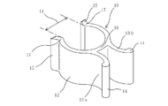
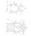
即ち本発明1はポンプ付容器用ストッパーに関し、容器(2)上部の開口部に螺着されるキャップ(3)と、前記キャップ(3)に設けられたポンプ(4)とを備えたポンプ付容器(1)に用いられ、前記ポンプ(4)が、前記キャップ(3)に取付けられたシリンダー(4a)と、前記シリンダー(4a)に前記キャップ(3)を貫通して設けられた流体吐出管(6)と、前記流体吐出管(6)に沿って上下動されるヘッド(7)とを有し、前記ヘッド(7)が押圧されると、前記ヘッド(7)の下端と前記キャップ(3)の上端とに当接することで、前記ヘッド(7)が下動されることを阻止する略円筒状に形成された本体部(12)を備えた、着脱自在なポンプ付容器用ストッパー(10)であって、前記本体部(12)に、前記流体吐出管(6)の外径よりも小さな幅の縦割溝(11)の両側に形成された一対の係止部(17)と、前記本体部(12)の外周面で周方向に所定の間隔を有して外方へ突出された一対のつまみ部(13a,13b)とが形成され、前記つまみ部(13a,13b)が互いに近接されると、この両つまみ部(13a,13b)間の周壁部分(16)を支点に、前記各係止部(17)が移動して互いに離隔される、ことを特徴とする。
(2)つまみ部を互いに近接するだけの簡単な操作により、つまみ部間の周壁部分を支点に係止部を移動させ、溝部の幅を広げることができ、ストッパーの着脱を容易に行うことができる。
(3)一対のつまみ部が本体部の周方向に所定の間隔を有しているので、このつまみ部を指先で押圧することにより、簡単かつ確実にストッパーを流体吐出管に取り付けることができる。
(4)装着されたストッパーの縦割溝が、流体吐出管の外径よりも小径であるので、ストッパーが流体吐出管から抜け落ちることなく、ストッパーを流体吐出管の周囲へ確実に取り付けることができる。
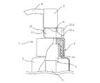
図1に示すように、このポンプ付容器(1)は、シャンプー、リンス、化粧液や調味料等の流体を内容物とする容器(2)と、前記の容器(2)の上端開口部に螺着される着脱自在なキャップ(3)と、このキャップ(3)に設けられたポンプ(4)とを備えている。このポンプ(4)は、キャップ(3)に取付けられたシリンダー(4a)と、シリンダー(4a)の下部に連結された流体吸入管(5)と、前記キャップ(3)を貫通して前記シリンダー(4a)の上部に連結された流体吐出管(6)と、この流体吐出管(6)に沿って上下動され、前記シリンダー(4a)内のピストンを駆動するヘッド(7)と、このヘッド(7)に設けられた流体吐出口(8)とを備える。上記の流体吐出管(6)には、ヘッド(7)とキャップ(3)との間に着脱自在なストッパー(10)が装着されている。
さらに上記の実施形態では、つまみ部の端部に突部を上下に長く形成したが、本発明では突部をこのような突条以外の形状でつまみ部に形成してもよく、つまみ部を指先でつまんだ際に、指に引っ掛かりとなる形状のものであればよい。また、本発明ではこの突部を省略したものであってもよい。
2 … 容器
3 … キャップ
4 … ポンプ
4a … シリンダー
6 … 流体吐出管
7 … ヘッド
10 … ストッパー
11 … 縦割溝
12 … 本体部
13a,13b… つまみ部
14 … 突部
15 … ガイド部
16 … 周壁(周壁部分)
17 … 係止部
Claims (6)
- 容器(2)上部の開口部に螺着されるキャップ(3)と、前記キャップ(3)に設けられたポンプ(4)とを備えたポンプ付容器(1)に用いられ、前記ポンプ(4)が、前記キャップ(3)に取付けられたシリンダー(4a)と、前記シリンダー(4a)に前記キャップ(3)を貫通して設けられた流体吐出管(6)と、前記流体吐出管(6)に沿って上下動されるヘッド(7)とを有し、前記ヘッド(7)が押圧されると、前記ヘッド(7)の下端と前記キャップ(3)の上端とに当接することで、前記ヘッド(7)が下動されることを阻止する略円筒状に形成された本体部(12)を備えた、着脱自在なポンプ付容器用ストッパー(10)であって、
前記本体部(12)に、前記流体吐出管(6)の外径よりも小さな幅の縦割溝(11)を形成する各係止部(17)と、前記本体部(12)の外周面で周方向に所定の間隔を有して外方へ突出された一対のつまみ部(13a,13b)とが形成され、前記つまみ部(13a,13b)が互いに近接されると、この両つまみ部(13a,13b)間の周壁部分(16)を支点に、前記各係止部(17)が移動して互いに離隔される、ことを特徴とするポンプ付容器用ストッパー。 - 前記各つまみ部(13a,13b)の端部に、突部(14)が形成された、請求項1に記載のポンプ付容器用ストッパー。
- 前記縦割溝(11)を形成する前記本体部(12)の各係止部(17)に、外方へ突出されたガイド部(15)が形成された、請求項1または請求項2に記載のポンプ付容器用ストッパー。
- 前記一方のつまみ部(13a,13b)と他方のつまみ部(13b,13a)との距離が、前記本体部(12)から遠くなるにつれて広くなるよう形成された、請求項1〜請求項3のいずれか1項に記載のポンプ付容器用ストッパー。
- 前記の各つまみ部(13a,13b)と本体部(12)の中心とを結ぶ仮想線で形成した中心角が、10°〜100°の範囲内である、請求項1〜請求項4のいずれか1項に記載のポンプ付容器用ストッパー。
- 前記各つまみ部(13a,13b)の端部を結ぶ仮想線が、前記支点を構成する周壁部分(16)よりも外側に位置する、請求項1〜請求項5のいずれか1項に記載のポンプ付容器用ストッパー。
Priority Applications (1)
| Application Number | Priority Date | Filing Date | Title |
|---|---|---|---|
| JP2010270317A JP5632725B2 (ja) | 2010-12-03 | 2010-12-03 | ポンプ付容器用ストッパー |
Applications Claiming Priority (1)
| Application Number | Priority Date | Filing Date | Title |
|---|---|---|---|
| JP2010270317A JP5632725B2 (ja) | 2010-12-03 | 2010-12-03 | ポンプ付容器用ストッパー |
Related Child Applications (1)
| Application Number | Title | Priority Date | Filing Date |
|---|---|---|---|
| JP2014169173A Division JP5873151B2 (ja) | 2014-08-22 | 2014-08-22 | ポンプ付容器用ストッパー |
Publications (2)
| Publication Number | Publication Date |
|---|---|
| JP2012115806A true JP2012115806A (ja) | 2012-06-21 |
| JP5632725B2 JP5632725B2 (ja) | 2014-11-26 |
Family
ID=46499312
Family Applications (1)
| Application Number | Title | Priority Date | Filing Date |
|---|---|---|---|
| JP2010270317A Active JP5632725B2 (ja) | 2010-12-03 | 2010-12-03 | ポンプ付容器用ストッパー |
Country Status (1)
| Country | Link |
|---|---|
| JP (1) | JP5632725B2 (ja) |
Cited By (1)
| Publication number | Priority date | Publication date | Assignee | Title |
|---|---|---|---|---|
| CN114261639A (zh) * | 2022-01-27 | 2022-04-01 | 浙江晟祺实业有限公司 | 一种乳液泵安全卡止装置 |
Citations (7)
| Publication number | Priority date | Publication date | Assignee | Title |
|---|---|---|---|---|
| JPS5953873U (ja) * | 1982-09-29 | 1984-04-09 | 株式会社吉野工業所 | 噴霧栓 |
| US4679712A (en) * | 1985-02-25 | 1987-07-14 | Realex Corporation | Orifice cover slide actuator lock for viscous product dispenser |
| JPH07548U (ja) * | 1993-06-04 | 1995-01-06 | 株式会社三谷バルブ | 内容物吐出容器の操作部ロック用部材 |
| WO2003048002A1 (fr) * | 2001-11-30 | 2003-06-12 | Sachiko Kitamura | Pompe-doseuse |
| JP2007069981A (ja) * | 2005-09-03 | 2007-03-22 | Yoshinobu Kasuya | ポンプ付きボトルの節約クリップ |
| JP2010082510A (ja) * | 2008-09-30 | 2010-04-15 | Yoshino Kogyosho Co Ltd | トリガー式液体噴出器 |
| JP2012091103A (ja) * | 2010-10-26 | 2012-05-17 | Yoshino Kogyosho Co Ltd | 泡吐出器 |
-
2010
- 2010-12-03 JP JP2010270317A patent/JP5632725B2/ja active Active
Patent Citations (7)
| Publication number | Priority date | Publication date | Assignee | Title |
|---|---|---|---|---|
| JPS5953873U (ja) * | 1982-09-29 | 1984-04-09 | 株式会社吉野工業所 | 噴霧栓 |
| US4679712A (en) * | 1985-02-25 | 1987-07-14 | Realex Corporation | Orifice cover slide actuator lock for viscous product dispenser |
| JPH07548U (ja) * | 1993-06-04 | 1995-01-06 | 株式会社三谷バルブ | 内容物吐出容器の操作部ロック用部材 |
| WO2003048002A1 (fr) * | 2001-11-30 | 2003-06-12 | Sachiko Kitamura | Pompe-doseuse |
| JP2007069981A (ja) * | 2005-09-03 | 2007-03-22 | Yoshinobu Kasuya | ポンプ付きボトルの節約クリップ |
| JP2010082510A (ja) * | 2008-09-30 | 2010-04-15 | Yoshino Kogyosho Co Ltd | トリガー式液体噴出器 |
| JP2012091103A (ja) * | 2010-10-26 | 2012-05-17 | Yoshino Kogyosho Co Ltd | 泡吐出器 |
Cited By (1)
| Publication number | Priority date | Publication date | Assignee | Title |
|---|---|---|---|---|
| CN114261639A (zh) * | 2022-01-27 | 2022-04-01 | 浙江晟祺实业有限公司 | 一种乳液泵安全卡止装置 |
Also Published As
| Publication number | Publication date |
|---|---|
| JP5632725B2 (ja) | 2014-11-26 |
Similar Documents
| Publication | Publication Date | Title |
|---|---|---|
| US10046349B2 (en) | Trigger-type pump dispenser | |
| US5226572A (en) | Bulb actuator for dropper closure | |
| EP2502851B1 (en) | Fixed quantity discharge squeeze container | |
| US20180168785A1 (en) | Pause valve and swivel assemblies for oral irrigator handle | |
| JP5873151B2 (ja) | ポンプ付容器用ストッパー | |
| EP2052992A1 (en) | Closure assembly with a levered lid opening mechanism | |
| EP1357049A2 (en) | Child resistant dispensing closure | |
| US20030094464A1 (en) | Fluid product dispenser with gripping member | |
| CN107249991A (zh) | 液体分装器 | |
| WO2017084626A1 (zh) | 分配器及包括该分配器的容器 | |
| KR20090008046U (ko) | 수동식 드롭퍼 | |
| CN206345203U (zh) | 一种手扣式喷头 | |
| JP5632725B2 (ja) | ポンプ付容器用ストッパー | |
| WO2008038480A1 (en) | Trigger spray and spray container having it | |
| JP6057767B2 (ja) | ポンプディスペンサ | |
| JP7343597B2 (ja) | 搾乳器 | |
| US20110198364A1 (en) | Container | |
| JP6991654B2 (ja) | 押下げポンプ用ホルダー | |
| KR101810534B1 (ko) | 잠금장치를 구비하는 펌프식 디스펜서 | |
| JP2003212261A (ja) | 液体吐出装置 | |
| JP2006206135A (ja) | ノズル付き容器 | |
| CN207595623U (zh) | 一种喷头 | |
| CN108852829A (zh) | 开塞露瓶 | |
| JP3552969B2 (ja) | エアゾール容器のキャップ | |
| JP2025091283A (ja) | キャップ付き容器 |
Legal Events
| Date | Code | Title | Description |
|---|---|---|---|
| A621 | Written request for application examination |
Free format text: JAPANESE INTERMEDIATE CODE: A621 Effective date: 20130606 |
|
| A977 | Report on retrieval |
Free format text: JAPANESE INTERMEDIATE CODE: A971007 Effective date: 20140619 |
|
| A131 | Notification of reasons for refusal |
Free format text: JAPANESE INTERMEDIATE CODE: A131 Effective date: 20140624 |
|
| A521 | Request for written amendment filed |
Free format text: JAPANESE INTERMEDIATE CODE: A523 Effective date: 20140822 |
|
| A131 | Notification of reasons for refusal |
Free format text: JAPANESE INTERMEDIATE CODE: A131 Effective date: 20140909 |
|
| A521 | Request for written amendment filed |
Free format text: JAPANESE INTERMEDIATE CODE: A523 Effective date: 20140916 |
|
| TRDD | Decision of grant or rejection written | ||
| A01 | Written decision to grant a patent or to grant a registration (utility model) |
Free format text: JAPANESE INTERMEDIATE CODE: A01 Effective date: 20141007 |
|
| A61 | First payment of annual fees (during grant procedure) |
Free format text: JAPANESE INTERMEDIATE CODE: A61 Effective date: 20141010 |
|
| R150 | Certificate of patent or registration of utility model |
Ref document number: 5632725 Country of ref document: JP Free format text: JAPANESE INTERMEDIATE CODE: R150 |
|
| R250 | Receipt of annual fees |
Free format text: JAPANESE INTERMEDIATE CODE: R250 |
|
| R250 | Receipt of annual fees |
Free format text: JAPANESE INTERMEDIATE CODE: R250 |
|
| R250 | Receipt of annual fees |
Free format text: JAPANESE INTERMEDIATE CODE: R250 |
|
| R250 | Receipt of annual fees |
Free format text: JAPANESE INTERMEDIATE CODE: R250 |
|
| R250 | Receipt of annual fees |
Free format text: JAPANESE INTERMEDIATE CODE: R250 |