JP2012116404A - Atmospheric pressure control air conditioner for vehicle - Google Patents
Atmospheric pressure control air conditioner for vehicle Download PDFInfo
- Publication number
- JP2012116404A JP2012116404A JP2010269557A JP2010269557A JP2012116404A JP 2012116404 A JP2012116404 A JP 2012116404A JP 2010269557 A JP2010269557 A JP 2010269557A JP 2010269557 A JP2010269557 A JP 2010269557A JP 2012116404 A JP2012116404 A JP 2012116404A
- Authority
- JP
- Japan
- Prior art keywords
- air
- vehicle
- window
- air conditioner
- pressure
- Prior art date
- Legal status (The legal status is an assumption and is not a legal conclusion. Google has not performed a legal analysis and makes no representation as to the accuracy of the status listed.)
- Pending
Links
- 238000005259 measurement Methods 0.000 claims description 8
- 238000005265 energy consumption Methods 0.000 claims description 7
- 230000006978 adaptation Effects 0.000 claims description 5
- 238000010586 diagram Methods 0.000 description 6
- CURLTUGMZLYLDI-UHFFFAOYSA-N Carbon dioxide Chemical compound O=C=O CURLTUGMZLYLDI-UHFFFAOYSA-N 0.000 description 4
- 238000004378 air conditioning Methods 0.000 description 3
- 239000006096 absorbing agent Substances 0.000 description 2
- QVGXLLKOCUKJST-UHFFFAOYSA-N atomic oxygen Chemical compound [O] QVGXLLKOCUKJST-UHFFFAOYSA-N 0.000 description 2
- 229910002092 carbon dioxide Inorganic materials 0.000 description 2
- 239000001569 carbon dioxide Substances 0.000 description 2
- 238000010276 construction Methods 0.000 description 2
- 238000001816 cooling Methods 0.000 description 2
- 238000001514 detection method Methods 0.000 description 2
- 230000000694 effects Effects 0.000 description 2
- 230000003340 mental effect Effects 0.000 description 2
- 229910052760 oxygen Inorganic materials 0.000 description 2
- 239000001301 oxygen Substances 0.000 description 2
- 230000029058 respiratory gaseous exchange Effects 0.000 description 2
- 230000035939 shock Effects 0.000 description 2
- 238000003915 air pollution Methods 0.000 description 1
- 238000007664 blowing Methods 0.000 description 1
- 238000004891 communication Methods 0.000 description 1
- 230000001143 conditioned effect Effects 0.000 description 1
- 230000003247 decreasing effect Effects 0.000 description 1
- 230000001934 delay Effects 0.000 description 1
- 230000006866 deterioration Effects 0.000 description 1
- 239000005357 flat glass Substances 0.000 description 1
- 230000006870 function Effects 0.000 description 1
- 239000004973 liquid crystal related substance Substances 0.000 description 1
- 238000000034 method Methods 0.000 description 1
- 238000005192 partition Methods 0.000 description 1
- 230000002093 peripheral effect Effects 0.000 description 1
- 230000002265 prevention Effects 0.000 description 1
- 239000003507 refrigerant Substances 0.000 description 1
- 230000000717 retained effect Effects 0.000 description 1
Images


Landscapes
- Air-Conditioning For Vehicles (AREA)
Abstract
Description
本発明は、自動車、鉄道車両などの車室内の気圧を制御する空調装置に関する。 The present invention relates to an air conditioner that controls the air pressure in a passenger compartment of an automobile, a railway vehicle, or the like.
気象条件により低気圧が通過する場合、車両が高速移動することでベンチュリー効果が起こる場合、標高が変化する場合、トンネルを通過する場合、など車両の車室内の気圧低下が起こることが知られている。そのような気圧低下の状態では、運転手(運転士)の思考能力、判断能力を含む心身能力の低下により、判断の遅れ、操作ミス、居眠りなどを誘い、事故の発生に結びつく可能性がある。
また、同乗者や乗客に快適な車内環境を提供するためにも、低気圧状態を避けて、気圧を標準気圧に維持することが望ましい。
It is known that when the low pressure passes due to meteorological conditions, the vehicle is moving at high speed, the venturi effect occurs, the altitude changes, the tunnel passes, etc. Yes. In such a pressure drop state, the driver's (driver's) thinking ability and mental and physical ability, including judgment ability, may be reduced, leading to delays in judgment, operational mistakes, and falling asleep, leading to the occurrence of an accident. .
Also, in order to provide a comfortable interior environment for passengers and passengers, it is desirable to maintain the atmospheric pressure at a standard atmospheric pressure while avoiding a low atmospheric pressure state.
特許文献1には、住宅の室内気圧調整システムが開示されている。室内の気圧の調整を可能とし、気圧の変動や天候の変化に関わらず、屋内全体や特定の居室の気圧を高気圧に保つものである。
特許文献2には、車両用空調装置が開示されている。車室内の気圧の変化により乗員が不快を感じることを防止することが可能な車両用空調装置である。
特許文献3には、居眠り運転防止装置が開示されている。車両の室内の空間を空気調和することによりドライバーの居眠り運転状態を防止する装置であり、車室内の気圧を検出し、しきい値以下ならば外気を導入するものである。
Patent Document 2 discloses a vehicle air conditioner. It is a vehicle air conditioner that can prevent a passenger from feeling uncomfortable due to a change in air pressure in a passenger compartment.
Patent Document 3 discloses a snooze driving prevention device. It is a device that prevents the driver's drowsy driving state by air-conditioning the vehicle interior space, detects the atmospheric pressure in the vehicle interior, and introduces outside air if it is below a threshold value.
本発明の発明者は、車室内の気圧を標準状態で維持する構成を提供すべく、いくつかの点における提案をするものである。
本発明は、車両用気圧制御にふさわしい空調装置を提供することを目的とする。
The inventor of the present invention makes proposals in several points in order to provide a configuration for maintaining the atmospheric pressure in the passenger compartment in a standard state.
An object of the present invention is to provide an air conditioner suitable for vehicle pressure control.
上記の課題を解決すべく、本発明の車両用気圧制御空調装置は以下の構成を有する。
気密構造を有する車室内の気圧を制御する車両用気圧制御空調装置であって、車室内の空気中の状態を測定する車室内空気状態センサと、外気の状態を測定する外気状態センサと、外気を前記車室内に取り込む過給送風機と、前記車室内の空気の一部を外部に排出する排気可動ダンパーと、前記車室内空気状態センサと前記外気状態センサとの測定結果に基づいて、前記排気可動ダンパー及び前記過給送風機とを制御する制御部とを有し、前記車室内の空気の圧力の低下を防止するものである。
In order to solve the above-described problems, the air pressure control air conditioner for a vehicle according to the present invention has the following configuration.
An air pressure control air conditioner for a vehicle that controls the air pressure in a vehicle interior having an airtight structure, the vehicle interior air state sensor that measures a state in the air in the vehicle interior, an outside air state sensor that measures the state of the outside air, and an outside air Based on the measurement results of the supercharging blower that takes in the vehicle interior, the exhaust movable damper that exhausts a part of the air in the vehicle interior to the outside, the vehicle interior air condition sensor, and the outside air condition sensor, And a control unit that controls the movable damper and the supercharging blower, and prevents a decrease in the pressure of the air in the passenger compartment.
また、吸気した外気の温度を調整する温度調整ユニットと、該温度調整ユニットに前記車室内の空気を循環させる内気循環可動ダンパーと、をさらに有し、前記制御部が、前記車室内空気状態センサの測定結果にしたがって前記排気可動ダンパーと前記内気循環可動ダンパーとの開閉を制御するとともに前記過給送風機の能力を制御して、前記温度調整ユニットのエネルギー消費を抑えるものとすることができる。なお、車内の空気を循環させる送風機を、別途単独で空調経路内に設置することでも可能である。 A temperature adjusting unit that adjusts the temperature of the outside air that has been taken in; and an inside air circulating movable damper that circulates air in the vehicle interior to the temperature adjusting unit, wherein the control unit includes the air condition sensor in the vehicle interior According to this measurement result, the opening and closing of the exhaust movable damper and the inside air circulating movable damper are controlled, and the capacity of the supercharging blower is controlled to suppress the energy consumption of the temperature adjustment unit. It is also possible to separately install a blower for circulating the air in the vehicle in the air conditioning path.
前記車両の窓またはドアの開閉操作を検知する窓・ドア開閉操作検知装置と、前記制御部の制御に従い前記車両の窓及びドアの開閉操作をロックする窓・ドア開閉ロック装置とをさらに有し、前記制御部は、前記窓・ドア開閉操作検知装置が、窓またはドアの開閉操作を検知すると、前記車室内空気状態センサの測定結果と前記外気状態センサの測定結果又は車室内と車外の圧力差を検知する機構(隔壁に設けた圧力差センサ)の結果に従い、内外の気圧差が所定の大きさ以下になるまで前記排気可動ダンパー及び前記過給送風機とを制御し、それまでは前記窓・ドア開閉ロック装置を働かせるものとすることができる。 A window / door opening / closing operation detecting device for detecting opening / closing operation of the window or door of the vehicle, and a window / door opening / closing locking device for locking the window and door opening / closing operation of the vehicle according to the control of the control unit. When the window / door opening / closing operation detecting device detects an opening / closing operation of the window or door, the control unit detects the measurement result of the vehicle interior air condition sensor and the measurement result of the outside air condition sensor or the pressure outside the vehicle interior and the exterior of the vehicle. According to the result of the mechanism for detecting the difference (pressure difference sensor provided on the partition wall), the exhaust movable damper and the supercharging blower are controlled until the pressure difference between the inside and the outside becomes a predetermined magnitude or less, and until then, the window -A door opening / closing lock device can be used.
前記制御部は、前記車両が運用される環境に応じた車内の気圧に制御することが望ましい。 It is desirable that the controller controls the atmospheric pressure in the vehicle according to the environment in which the vehicle is operated.
前記制御部は、長期間にわたり低気圧状態が続く場合には、人体が低気圧状態に順応する度合いを考慮して車内の設定圧力を調整することが望ましい。 When the low pressure state continues for a long time, the control unit desirably adjusts the set pressure in the vehicle in consideration of the degree to which the human body adapts to the low pressure state.
気圧低下の事実を当該車両の運転手に知らせ警告を与える気圧低下警告装置をさらに有し、前記制御部は、当該気圧低下警告装置により、運転手に警告を与えることが望ましい。 It is desirable to further include a pressure drop warning device for notifying the driver of the vehicle of the pressure drop and giving a warning, and for the controller to give a warning to the driver by the pressure drop warning device.
本発明の構成によれば、次のような効果が期待できる。
1.運転手(運転士)の心身能力の低下を防止する。
2.同乗者や乗客の環境を快適に保つ。
According to the configuration of the present invention, the following effects can be expected.
1. Prevents the driver's (driver) 's mental and physical deterioration.
2. Keep passengers and passengers comfortable.
以下、本発明の実施形態を説明する。
車体の室内を気密構造とし、車体外部より可動式のダンパー(給気可動ダンパー)を経て大気を取り入れ(又は走行風を取り入れ)、フィルターを通過させたのち、(過給のできる)送風機を経て、熱交換器(ヒーターユニット・冷却ユニット)を通過させ、車内に供給する。但し、フィルターや送風機またはヒーターユニット及び冷却ユニットの配置は、順序にこだわらない。また、熱交換器などを経た後に外気と混合する方法でもよい。
車両の室内、または室内及び車外に大気の圧力を測定するセンサーを設置し、給気可動ダンバーと排気可動ダンバーの操作により、または送風機の能力を可変することにより、車内の空気の圧力を常に標準気圧に維持する。または過給能力や車体の強度に応じて標準気圧に近づける。
人体に影響のない程度の、標準気圧以上の高気圧状態でもよい。
なお、自動車の場合には、通常は上記給気可動ダンパーを設置するのに対し、鉄道車両の場合には、給気可動ダンパーを省略することもできる。
Embodiments of the present invention will be described below.
The interior of the car body is airtight, air is taken from the outside of the car body via a movable damper (air supply movable damper) (or running air is taken in), passed through a filter, and then passed through a blower (which can be supercharged) Then, it passes through the heat exchanger (heater unit / cooling unit) and supplies it to the car. However, the arrangement of the filter, blower, heater unit and cooling unit is not particular to the order. Moreover, the method of mixing with external air after passing through a heat exchanger etc. may be used.
A sensor that measures atmospheric pressure inside the vehicle or inside and outside the vehicle is installed, and the air pressure inside the vehicle is always standardized by operating the air supply movable exhaust and exhaust movable dampers or by varying the capacity of the blower. Maintain at atmospheric pressure. Or close to the standard pressure according to the supercharging ability and the strength of the vehicle body.
It may be in a high-pressure state above the standard pressure so as not to affect the human body.
In the case of an automobile, the air supply movable damper is usually installed, whereas in the case of a railway vehicle, the air supply movable damper can be omitted.
常に気圧の低い高地で使用する場合には、大気圧力の変化を車外のセンサーで監視し、その環境に見合った、圧力となるように自動的に調整する。または手動で標高を入力することにより設定する。 When using at high altitudes where the atmospheric pressure is always low, changes in atmospheric pressure are monitored by sensors outside the vehicle and automatically adjusted to a pressure suitable for the environment. Alternatively, set the altitude manually.
外気を空調ユニットで温度調整時、車内の人間の呼吸などによる空気の汚れをセンサーで監視し、排気可動ダンバー及び給気可動ダンパー開閉度制御並びに、車内循環の可動ダンパー開閉制御、または送風機の能力を制御することで、車内の調和された空気を無駄に排出しない。それにより大きな動力を消費する冷媒の圧縮機の作動を抑え省エネを図る。 When adjusting the temperature of the outside air with the air conditioning unit, air pollution due to human breathing etc. in the car is monitored with a sensor, the exhaust movable damper and the air supply movable damper open / closed degree control, the internal circulation movable damper open / close control, or the blower ability By controlling, the conditioned air in the vehicle is not exhausted wastefully. This reduces energy consumption by suppressing the operation of the refrigerant compressor, which consumes a large amount of power.
室内が加圧状態では、窓ガラスが窓枠に押し付けられていて、開けることが困難になる。またドアを開ける場合に、勢いよく開いてしまう危険性がある。
それを防ぐため、例えばパワーウインドウの場合に窓をあけるスイッチ操作を検知し、ドアの場合にドアノブに手をかける動作を検知し、それを引き金として車内と車外の圧力を比較し、圧力差をなくしてから窓あけまたはドア開けが作動する構造とする。圧力差が所定の大きさある場合には開かない構造とすることもできる。
When the room is pressurized, the window glass is pressed against the window frame, making it difficult to open. Also, when opening the door, there is a risk that it will open vigorously.
To prevent this, for example, the switch operation that opens the window in the case of a power window is detected, and the action of putting a hand on the door knob in the case of a door is detected. A structure that opens the window or opens the door after it is lost. When the pressure difference is a predetermined magnitude, it may be configured not to open.
ドアの場合には、開放側に速度制御する、油圧ダンパーなどの緩衝装置を設けることもできる。
開放側への速度制御、油圧ダンパーなどの緩衝装置を設けることは、後方から強風が吹いている場合に、急激にドアが開くことを防止する効果も期待できる。
In the case of a door, a shock absorber such as a hydraulic damper that controls the speed on the open side can be provided.
Providing shock absorbers such as speed control to the open side and hydraulic dampers can also be expected to prevent the door from opening suddenly when strong wind is blowing from the rear.
鉄道車両の昇降口のドアを開ける場合は、基本的に駅に停車して、ドアを開く場合のみを考慮すればよいから、車両の走行速度が設定した速度以下になった場合に、加圧状態を解除することで対応できる。
乗務員の手動操作による加圧状態の解除も可能である。圧力差がある場合にはドアが開かないこととする制御をすることが安全管理上望ましい。
When opening the door of a railway vehicle's elevator door, basically you only have to consider when you stop at the station and open the door, so if the vehicle's traveling speed falls below the set speed, pressurize It can be dealt with by releasing the state.
It is also possible to release the pressurized state by manual operation of the crew. It is desirable for safety management that the door is not opened when there is a pressure difference.
次に、図1から図6までを参照しつつ、実施例1から実施例6までについて説明する。 Next, examples 1 to 6 will be described with reference to FIGS.
図1は、本発明に係る車両用気圧制御空調装置の主要な構成を実施例1について示す図である。図1(a)は、自動車の外観を示す。右が前方である。ここでは、乗用車を例に挙げた。トラックなどの商用車、工事車両、鉄道車両であってもよい。 FIG. 1 is a diagram showing a main configuration of an atmospheric pressure control air conditioner for a vehicle according to the present invention in the first embodiment. Fig.1 (a) shows the external appearance of a motor vehicle. The right is the front. Here, a passenger car is taken as an example. Commercial vehicles such as trucks, construction vehicles, and railway vehicles may also be used.
図1(b)は、車室内に車両用気圧制御空調装置を施す場合の全体構成を示す図である。車室1は、気密度の高いものとして構成される。ドア・窓(図1においては描くのを省略してある。)などの外気との出し入れがなされる部分では、閉じた状態における気密度を高くする。
FIG.1 (b) is a figure which shows the whole structure in the case of providing a vehicle atmospheric | air pressure control air conditioner in a vehicle interior. The
車室1には、外気を取り入れるダクトである給気ダクト20及び車室1内の空気を外部に排出するダクトである排気ダクト25が車室1と同様に気密度の高いものとして設けられる。給気ダクト20の外気取り入れ口付近には、給気可動ダンパー21が設けられ、排気ダクト25には排気可動ダンパー24が設けられる。これらの二つの可動ダンパーは、モーターを駆動することなどにより開閉度を制御可能なダンパーであり、閉まっている状態では気密度が車室1と同様に高いものである。また、これらの二つの可動ダンパーは、単に開け閉めだけでなく、開き具合を段階的に(又は連続的に)調整できるものが望ましい。
The
車室1内には車室内状態センサ11が設けられ、給気ダクト20の外気取り入れ口付近には、外気状態センサ12が設けられる。これらのセンサは、少なくとも気圧を検知できるものである。そのほかに酸素濃度、二酸化炭素濃度などを検知するものであることが望ましい。
A vehicle
給気ダクト20の途中には、エアフィルター32と過給送風機31とが設けられ、給気可動ダンパー21が開いている状態において、エアフィルター32を介して取り込まれた外気は、過給送風機31によって車室1内に送り込まれる。給気可動ダンパー21の開閉、排気可動ダンパー24の開閉、過給送風機31の動作は、制御部90の制御によりなされる。すなわち、車室内空気状態センサ11が車室内1の気圧を監視し、それが標準気圧よりも低下したことを検知すると、制御部90は、それに基づいて給気可動ダンパー21を開き、過給送風機31を動作させる。このとき、外気状態センサ12により計測された外気圧がどれだけであるかをも参照し、また過給送風機31の能力の限界をも考慮して、制御部90は、給気可動ダンパー21の開き具合を調整する。車室1内の気圧が標準状態に戻ると、制御部90は、給気可動ダンパー21を閉めて、過給送風機31を停止させる。また、運転手(運転士)、同乗者の呼吸などにより車室内の空気中の二酸化炭素濃度が高まり、酸素濃度が低くなることを防止するために、過給送風機31を運転しつつ、排気可動ダンパー24を若干開ける制御も必要となる。
In the middle of the
図2は、温度調整ユニットとの結合をした実施例2を示す図である。実施例1と共通の要素については、同一の符号をもって示してある。異なる部分について、説明する。実施例2にあっては、車室1内の空気を過給送風機31の前面に循環させる内気循環ダクト23を設け、その内部には、内気循環可動ダンパー22を設けた。また、温度調整ユニット30を過給送風機31と車室1との間に設けた。内気循環可動ダンパー22は、給気可動ダンパー21と同様の機能をもつダンパーであり、給気可動ダンバー21が開くときには閉じているように制御部90により制御される。また、内気循環可動ダンパー22が開くときには、給気可動ダンパー21は閉じるように制御部90により制御される。
FIG. 2 is a diagram showing a second embodiment combined with a temperature adjustment unit. Elements common to the first embodiment are denoted by the same reference numerals. Different parts will be described. In Example 2, the inside
温度調整ユニット30は、空気の温度を調整するものであり、熱交換器、エバポレータ、ヒーターユニットなどにより構成される。制御部90により、温度調整ユニット30、過給送風機31、内気循環可動ダンパー22、給気可動ダンパー21を制御することにより、車室1内の空気の温度を効率的に、またエネルギー消費を抑えつつ、温める、または冷やすことが可能となる。
The
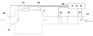
図3は、窓・ドア開閉ロック装置との結合をした実施例3を示す図である。実施例1と共通する要素については、同一の符号をもって示してある。実施例1と異なるのは、運転手または同乗者が窓またはドアの開閉操作をしようとすることを検知して、制御部90に知らせる窓・ドア開閉操作検知装置41と、制御部90により制御され窓またはドアの開閉操作をロックする窓・ドア開閉ロック装置42とを設けたものである。車室内1と外気圧との差が所定の値よりも大きい時には、窓やドアを開け閉めすることに危険が伴う場合がある。そこで、車室内空気状態センサ11による気圧と外気状態センサ12による気圧との差が所定値以上ある場合に、窓・ドア開閉操作検知装置41が運転手または同乗者の窓・ドア開閉操作を検知すると、制御部90はその窓・ドアの開閉がすぐにはできないように窓・ドア開閉ロック装置42を働かせる。それとともに、排気可動ダンパー24、給気可動ダンパー21、過給送風機31の制御をすることにより、車室1内の気圧を外気圧に近づける。内外の気圧差が所定値以下になると窓・ドア開閉ロック装置42のロック状態を制御部90が解除して、窓またはドアを開閉可能となる。
FIG. 3 is a view showing Example 3 combined with a window / door opening / closing lock device. Elements common to the first embodiment are denoted by the same reference numerals. The difference from the first embodiment is that the driver / passenger detects that the driver or passenger is going to open / close the window or door, and notifies the
図4は、高地などの環境に応じた制御をする実施例4を示す図である。図4(b)にその主な構成を示す。実施例1と共通要素については同一符号を用いてある。異なるのは、高度計13を有する点である。ここで、高度計13は、当該車両が現在存在する場所の高度を測定する機器である。例えば、既知の高度の場所から車体の傾斜を連続的に測定し、走行距離について積分することにより高度を算出する高度計が考えられる。また、GPS装置などにより緯度と経度を求め、テーブルを参照してその場所の高度を求めるものであってもよい。最も簡単には、気圧を測定してそれを高度に換算するものとすることができる。
FIG. 4 is a diagram illustrating a fourth embodiment that performs control according to an environment such as a highland. FIG. 4B shows the main configuration. The same reference numerals are used for the common elements with the first embodiment. The difference is that it has an
図4(a)は、制御部90をいわゆるマイクロコンピュータ(処理装置99)により構成する場合について、その構成を示したものである。処理装置99のバスには、当該処理装置99の作業領域であるメモリ98、当該処理装置99のプログラムを記憶するプログラム記憶装置97、外部周辺装置とのやりとりをするためのインタフェース部(図示を省略)、高度履歴記録装置91が設けられる。処理装置99は、車両が高地を旅行している際など、高度に見合った処理をするように働く。高地を旅行しているにも関わらず、低地と同様の処理をしていたのでは、エネルギー消費が大きくなりすぎる。また、長い時間高地にいる場合には、ある程度、人間の順応によりカバーできると考えられる。したがって、ある程度長い時間、高地を旅行している場合には、標準気圧を低い側にシフトさせることにより、エネルギー消費を抑える。
高地を旅行する場合だけでなく、高地に居住する人が車両を利用する場合も同様である。
この車両が、ナビゲータを備えている場合には、そのナビゲータシステムと連動させて、目的地に至るまでに通過する道路の高度をあらかじめ予測し、それに見合った標準気圧の設定をすることもできる。
FIG. 4A shows the configuration of the
The same applies not only when traveling in the highlands, but also when a person living in the highlands uses the vehicle.
When this vehicle is equipped with a navigator, the altitude of the road passing through to the destination can be predicted in advance in conjunction with the navigator system, and the standard atmospheric pressure can be set accordingly.
図5は、低気圧状態が続いた履歴に基づいて気圧を調整する実施例5を示す図である。図5(b)に示すように、ハードウェア構成のほとんどが図1に示す実施例1と共通であり、共通要素については同一符号を用いてある。図5(a)は、制御部90の構成を詳しく示している。図4(a)と共通要素については、同一符号を用いてある。実施例5にあっては、気圧履歴記録装置92が設けられ、車室内空気状態センサ11により測定された気圧を所定の時間間隔で記録する。また、気圧順応データ記録装置93が設けられ、どれだけの気圧の状態がどれだけの時間続いたら、標準的な人間がそれに順応できるかを対応付ける情報が記録されている。処理装置99は、気圧履歴記録装置92に記録された情報に基づいて、気圧順応データ記録装置93の情報を参照して車室1内の空気を保つべき気圧(標準気圧)をシフトさせる。これにより、過給送風機31の運転時間を短くし、エネルギー消費を抑えることができる。
FIG. 5 is a diagram illustrating a fifth embodiment in which the atmospheric pressure is adjusted based on a history of low pressure conditions continuing. As shown in FIG. 5B, most of the hardware configuration is common to the first embodiment shown in FIG. 1, and the same reference numerals are used for common elements. FIG. 5A shows the configuration of the
図6は、気圧低下警告装置61を設けた実施例6を示す図である。運転手が気圧の低下の事実を知ることは事故防止の上で重要なことである。運転手が見やすい位置にランプの点灯により気圧の低下の事実、過給送風機の運転の事実などを知らせることとするのが実施例6であり、そのための装置が気圧低下警告装置である。最も簡単には、ランプの点灯、消滅によりそれを知らせることができる。車室内外の気圧を数値化したデータ、保持すべき気圧値として現在設定されている値などの数値を液晶画面などで運転手にわかるように表示することとしてもよい。さらに、各可動ダンパーの開閉度、温度調整ユニットの状態、車室内外の温度などをあわせて表示することとしてもよい。、
FIG. 6 is a diagram showing a sixth embodiment in which an atmospheric pressure
本発明は、自動車の車両、工事用の作業車両、鉄道車両、など車両一般の車室内の空調装置に利用可能である。運転室内に利用可能である。また、客室にも利用可能である。 INDUSTRIAL APPLICABILITY The present invention can be used for an air conditioner in a vehicle interior of a vehicle such as an automobile vehicle, a construction work vehicle, and a railway vehicle. It can be used in the cab. It can also be used in guest rooms.
1 車室
10 車両用気圧制御空調装置
11 車室内空気状態センサ
12 外気状態センサ
13 高度計
20 給気ダクト
21 給気可動ダンパー
22 内気循環可動ダンパー
23 内気循環ダクト
24 排気可動ダンパー
25 排気ダクト
30 温度調整ユニット
31 過給送風機
32 エアフィルター
41 窓・ドア開閉操作検知装置
42 窓・ドア開閉ロック装置
61 気圧低下警告装置
90 制御部
91 高度履歴記録装置
92 気圧履歴記録装置
93 気圧順応データ記録装置
97 プログラム
98 メモリ
99 処理装置
DESCRIPTION OF
Claims (6)
車室内の空気中の状態を測定する車室内空気状態センサと、
外気の状態を測定する外気状態センサと、
外気を前記車室内に取り込む過給送風機と、
前記車室内の空気の一部を外部に排出する排気可動ダンパーと、
前記車室内空気状態センサと前記外気状態センサとの測定結果に基づいて、前記過給送風機及び前記排気可動ダンパーとを制御する制御部とを有し、前記車室内の空気の圧力の低下を防止する車両用気圧制御空調装置。 An air pressure control air conditioner for a vehicle that controls the air pressure in a passenger compartment having an airtight structure,
A vehicle interior air condition sensor for measuring the state of the vehicle interior in air;
An outside air condition sensor for measuring the outside air condition;
A supercharger blower for taking outside air into the vehicle interior;
An exhaust movable damper that discharges part of the air in the vehicle interior to the outside;
A control unit that controls the supercharger blower and the exhaust movable damper based on the measurement results of the vehicle interior air condition sensor and the outside air condition sensor, and prevents a decrease in air pressure in the vehicle interior Air pressure control air conditioner for vehicles.
外部から吸気した空気の温度を調整する温度調整ユニットと、
該温度調整ユニットに前記車室内の空気を循環させる内気循環ダクトと、
該内気循環ダクト内に設けられ、該内気循環ダクトの開閉を行う内気循環可動ダンパーと、
をさらに有し、
前記制御部が、前記車室内空気状態センサの測定結果にしたがって前記排気可動ダンパーと前記内気循環可動ダンパーの開閉を制御するとともに前記過給送風機の能力を制御して、前記温度調整ユニットのエネルギー消費を抑えることを特徴とする車両用気圧制御空調装置。 The air pressure control air conditioner for a vehicle according to claim 1,
A temperature adjustment unit that adjusts the temperature of the air taken in from the outside,
An internal air circulation duct for circulating the air in the vehicle interior to the temperature adjustment unit;
An inside air circulation movable damper provided in the inside air circulation duct for opening and closing the inside air circulation duct;
Further comprising
The control unit controls the opening and closing of the exhaust movable damper and the inside air circulating movable damper according to the measurement result of the vehicle interior air condition sensor, and also controls the capacity of the supercharging blower, so that the energy consumption of the temperature adjustment unit The air pressure control air conditioner for vehicles characterized by suppressing.
前記車両の窓またはドアの開閉操作を検知する窓・ドア開閉操作検知装置と、
前記制御部の制御に従い前記車両の窓及びドアの開閉操作をロックする窓・ドア開閉ロック装置と
をさらに有し、
前記制御部は、前記窓・ドア開閉操作検知装置が、窓またはドアの開閉操作を検知すると、前記車室内空気状態センサの測定結果と前記外気状態センサの測定結果とに従い、内外の気圧差が所定の大きさ以下になるまで前記過給送風機とを制御し、それまでは前記窓・ドア開閉ロック装置を働かせることを特徴とする車両用気圧制御空調装置。 The air pressure control air conditioner for a vehicle according to claim 1,
A window / door opening / closing operation detecting device for detecting opening / closing operation of the window or door of the vehicle;
A window / door open / close lock device that locks the window and door open / close operation of the vehicle according to the control of the control unit;
When the window / door opening / closing operation detecting device detects an opening / closing operation of the window or door, the control unit detects a difference between the internal and external pressures according to the measurement result of the vehicle interior air condition sensor and the measurement result of the outside air condition sensor. The air pressure control air conditioner for vehicles, wherein the supercharger blower is controlled until a predetermined size or less, and the window / door opening / closing lock device is operated until then.
前記制御部は、前記車両が運用される環境に応じた車内の気圧に制御することを特徴とする車両用気圧制御空調装置。 The air pressure control air conditioner for a vehicle according to claim 1,
The said control part controls the atmospheric | air pressure control air conditioner for vehicles according to the atmospheric | air pressure in a vehicle according to the environment where the said vehicle is operate | moved.
前記制御部は、長期間にわたり低気圧状態が続く場合には、人体が低気圧状態に順応する度合いを考慮して車内の設定圧力を調整することを特徴とする車両用気圧制御空調装置。 The air pressure control air conditioner for a vehicle according to claim 1,
When the low pressure state continues for a long period of time, the control unit adjusts the set pressure in the vehicle in consideration of the degree of adaptation of the human body to the low pressure state.
気圧低下の事実を当該車両の運転手に知らせ警告を与える気圧低下警告装置
をさらに有し、
前記制御部は、当該気圧低下警告装置により、運転手に警告を与えることを特徴とする車両用気圧制御空調装置。 The air pressure control air conditioner for a vehicle according to claim 1,
A pressure drop warning device for notifying the vehicle driver of the fact of the pressure drop and giving a warning;
The control unit gives a warning to the driver by the atmospheric pressure drop warning device.
Priority Applications (1)
| Application Number | Priority Date | Filing Date | Title |
|---|---|---|---|
| JP2010269557A JP2012116404A (en) | 2010-12-02 | 2010-12-02 | Atmospheric pressure control air conditioner for vehicle |
Applications Claiming Priority (1)
| Application Number | Priority Date | Filing Date | Title |
|---|---|---|---|
| JP2010269557A JP2012116404A (en) | 2010-12-02 | 2010-12-02 | Atmospheric pressure control air conditioner for vehicle |
Publications (1)
| Publication Number | Publication Date |
|---|---|
| JP2012116404A true JP2012116404A (en) | 2012-06-21 |
Family
ID=46499774
Family Applications (1)
| Application Number | Title | Priority Date | Filing Date |
|---|---|---|---|
| JP2010269557A Pending JP2012116404A (en) | 2010-12-02 | 2010-12-02 | Atmospheric pressure control air conditioner for vehicle |
Country Status (1)
| Country | Link |
|---|---|
| JP (1) | JP2012116404A (en) |
Cited By (5)
| Publication number | Priority date | Publication date | Assignee | Title |
|---|---|---|---|---|
| JP2018012490A (en) * | 2016-07-18 | 2018-01-25 | トヨタ モーター エンジニアリング アンド マニュファクチャリング ノース アメリカ,インコーポレイティド | Automatic window synchronization system |
| JP2022140123A (en) * | 2021-03-12 | 2022-09-26 | 株式会社Subaru | Atmospheric pressure control device and vehicle including atmospheric pressure control device |
| CN115782537A (en) * | 2018-03-26 | 2023-03-14 | 本田技研工业株式会社 | Internal environment adjustment device and internal environment adjustment method |
| CN115989154A (en) * | 2020-09-21 | 2023-04-18 | 万国卡车知识产权有限公司 | Vehicle occupant protection |
| CN117863832A (en) * | 2023-03-29 | 2024-04-12 | 莆田市凯顿品牌管理有限公司 | Air boost system for a vehicle |
Citations (8)
| Publication number | Priority date | Publication date | Assignee | Title |
|---|---|---|---|---|
| JPH058724A (en) * | 1991-06-28 | 1993-01-19 | Yokogawa Electric Corp | Indoor-pressure control device |
| JPH06191261A (en) * | 1992-12-25 | 1994-07-12 | Isuzu Motors Ltd | Dozing driving preventing device |
| JPH07329576A (en) * | 1994-06-13 | 1995-12-19 | Central Jidosha Kk | Automovile cabin air pressure control device |
| JPH09226355A (en) * | 1995-12-20 | 1997-09-02 | Zexel Corp | Control method of indoor atmospheric pressure and indoor atmospheric pressure control device |
| JP2004276883A (en) * | 2003-03-19 | 2004-10-07 | Denso Corp | Vehicle air conditioner |
| JP2005238911A (en) * | 2004-02-25 | 2005-09-08 | Kawasaki Heavy Ind Ltd | Control method and control apparatus for vehicle air conditioner |
| JP2007196710A (en) * | 2006-01-23 | 2007-08-09 | Denso Corp | Car interior / external pressure difference reduction device |
| JP2010163017A (en) * | 2009-01-15 | 2010-07-29 | Epson Toyocom Corp | Pressure regulator, and vehicular pressure regulating method |
-
2010
- 2010-12-02 JP JP2010269557A patent/JP2012116404A/en active Pending
Patent Citations (8)
| Publication number | Priority date | Publication date | Assignee | Title |
|---|---|---|---|---|
| JPH058724A (en) * | 1991-06-28 | 1993-01-19 | Yokogawa Electric Corp | Indoor-pressure control device |
| JPH06191261A (en) * | 1992-12-25 | 1994-07-12 | Isuzu Motors Ltd | Dozing driving preventing device |
| JPH07329576A (en) * | 1994-06-13 | 1995-12-19 | Central Jidosha Kk | Automovile cabin air pressure control device |
| JPH09226355A (en) * | 1995-12-20 | 1997-09-02 | Zexel Corp | Control method of indoor atmospheric pressure and indoor atmospheric pressure control device |
| JP2004276883A (en) * | 2003-03-19 | 2004-10-07 | Denso Corp | Vehicle air conditioner |
| JP2005238911A (en) * | 2004-02-25 | 2005-09-08 | Kawasaki Heavy Ind Ltd | Control method and control apparatus for vehicle air conditioner |
| JP2007196710A (en) * | 2006-01-23 | 2007-08-09 | Denso Corp | Car interior / external pressure difference reduction device |
| JP2010163017A (en) * | 2009-01-15 | 2010-07-29 | Epson Toyocom Corp | Pressure regulator, and vehicular pressure regulating method |
Cited By (7)
| Publication number | Priority date | Publication date | Assignee | Title |
|---|---|---|---|---|
| JP2018012490A (en) * | 2016-07-18 | 2018-01-25 | トヨタ モーター エンジニアリング アンド マニュファクチャリング ノース アメリカ,インコーポレイティド | Automatic window synchronization system |
| CN115782537A (en) * | 2018-03-26 | 2023-03-14 | 本田技研工业株式会社 | Internal environment adjustment device and internal environment adjustment method |
| CN115989154A (en) * | 2020-09-21 | 2023-04-18 | 万国卡车知识产权有限公司 | Vehicle occupant protection |
| JP2023542184A (en) * | 2020-09-21 | 2023-10-05 | インターナショナル トラック インテレクチュアル プロパティー カンパニー リミテッド ライアビリティー カンパニー | Vehicle occupant protection |
| JP2022140123A (en) * | 2021-03-12 | 2022-09-26 | 株式会社Subaru | Atmospheric pressure control device and vehicle including atmospheric pressure control device |
| JP7609664B2 (en) | 2021-03-12 | 2025-01-07 | 株式会社Subaru | Air pressure control device and vehicle including the air pressure control device |
| CN117863832A (en) * | 2023-03-29 | 2024-04-12 | 莆田市凯顿品牌管理有限公司 | Air boost system for a vehicle |
Similar Documents
| Publication | Publication Date | Title |
|---|---|---|
| CN103144512B (en) | A kind of vehicle and vehicle scavenge control method and device | |
| US20120015594A1 (en) | Demand-based fresh air control system | |
| EP3074252B1 (en) | Fresh air control for a transport refrigeration unit | |
| JP2012116404A (en) | Atmospheric pressure control air conditioner for vehicle | |
| CN106515374A (en) | Vehicle interior ventilation control method and device | |
| CN112498388B (en) | Rail transit vehicle and control method and control system thereof | |
| JP2016521655A (en) | Adaptive indoor air quality control apparatus and method for vehicle compartment | |
| EP3202634B1 (en) | Railway car having air conditioning devices in engineer's cabin, galley, and passenger cabin | |
| CN106004322B (en) | Air conditioning for automobiles fresh air air door energy-saving control method and system | |
| CN110722962A (en) | Vehicle air purification method and device and vehicle | |
| CN101865516A (en) | Device and method for controlling concentration of carbon dioxide in car | |
| CN115519971A (en) | A kind of intelligent control method of fresh air ratio in car cockpit and car air conditioner | |
| KR101430011B1 (en) | Vehicle air conditioning system | |
| CN113085486A (en) | Integrated air curtain system for vehicle and vehicle | |
| CN203236998U (en) | Novel automotive air conditioner capable of automatically detecting air and exchanging air | |
| KR20080095510A (en) | CO2 concentration control system inside the vehicle | |
| CN117284050A (en) | In-vehicle safety control method, electronic device, vehicle and storage medium | |
| CN201970946U (en) | Safety protection device used for vehicle | |
| KR101344522B1 (en) | A Ventilating Method for a Vehicle | |
| KR20190014831A (en) | Inside the car Life protection device | |
| CN202703185U (en) | Vehicle-mounted air conditioning system | |
| CN109532385A (en) | One kind preventing fatigue driving system | |
| WO2020143563A1 (en) | Solar air monitoring and automatic temperature control system for vehicle | |
| CN204978151U (en) | Car early warning system and car | |
| CN208118886U (en) | The air conditioning for automobiles of integrated carbon dioxide sensor linkage control |
Legal Events
| Date | Code | Title | Description |
|---|---|---|---|
| A131 | Notification of reasons for refusal |
Free format text: JAPANESE INTERMEDIATE CODE: A131 Effective date: 20120731 |
|
| A521 | Written amendment |
Free format text: JAPANESE INTERMEDIATE CODE: A523 Effective date: 20120928 |
|
| A131 | Notification of reasons for refusal |
Free format text: JAPANESE INTERMEDIATE CODE: A131 Effective date: 20130129 |
|
| A02 | Decision of refusal |
Free format text: JAPANESE INTERMEDIATE CODE: A02 Effective date: 20130604 |