JP2012117747A - Cooking device - Google Patents
Cooking device Download PDFInfo
- Publication number
- JP2012117747A JP2012117747A JP2010267759A JP2010267759A JP2012117747A JP 2012117747 A JP2012117747 A JP 2012117747A JP 2010267759 A JP2010267759 A JP 2010267759A JP 2010267759 A JP2010267759 A JP 2010267759A JP 2012117747 A JP2012117747 A JP 2012117747A
- Authority
- JP
- Japan
- Prior art keywords
- water
- tank
- steam
- amount
- pipe
- Prior art date
- Legal status (The legal status is an assumption and is not a legal conclusion. Google has not performed a legal analysis and makes no representation as to the accuracy of the status listed.)
- Pending
Links
- 238000010411 cooking Methods 0.000 title claims abstract description 67
- XLYOFNOQVPJJNP-UHFFFAOYSA-N water Substances O XLYOFNOQVPJJNP-UHFFFAOYSA-N 0.000 claims abstract description 245
- 238000010438 heat treatment Methods 0.000 claims abstract description 25
- 239000008400 supply water Substances 0.000 claims abstract description 5
- 230000002265 prevention Effects 0.000 claims description 8
- 239000003595 mist Substances 0.000 description 28
- 238000004140 cleaning Methods 0.000 description 23
- 235000013305 food Nutrition 0.000 description 13
- 238000002347 injection Methods 0.000 description 11
- 239000007924 injection Substances 0.000 description 11
- 238000000034 method Methods 0.000 description 8
- 238000005553 drilling Methods 0.000 description 6
- 239000004744 fabric Substances 0.000 description 6
- 238000001704 evaporation Methods 0.000 description 4
- 230000002093 peripheral effect Effects 0.000 description 4
- 235000019583 umami taste Nutrition 0.000 description 4
- 230000005540 biological transmission Effects 0.000 description 3
- 230000008020 evaporation Effects 0.000 description 3
- 239000007788 liquid Substances 0.000 description 3
- 238000003825 pressing Methods 0.000 description 3
- 238000011144 upstream manufacturing Methods 0.000 description 3
- 238000007664 blowing Methods 0.000 description 2
- 238000010586 diagram Methods 0.000 description 2
- 238000006073 displacement reaction Methods 0.000 description 2
- 239000008237 rinsing water Substances 0.000 description 2
- 238000005507 spraying Methods 0.000 description 2
- 230000006866 deterioration Effects 0.000 description 1
- 230000000694 effects Effects 0.000 description 1
- 230000020169 heat generation Effects 0.000 description 1
- 239000011810 insulating material Substances 0.000 description 1
- 239000000463 material Substances 0.000 description 1
- 238000005192 partition Methods 0.000 description 1
- 230000000149 penetrating effect Effects 0.000 description 1
- 239000000843 powder Substances 0.000 description 1
- 238000000638 solvent extraction Methods 0.000 description 1
- 238000010792 warming Methods 0.000 description 1
- 238000005406 washing Methods 0.000 description 1
- 230000037303 wrinkles Effects 0.000 description 1
Images





Landscapes
- Commercial Cooking Devices (AREA)
Abstract
Description
本発明は、被調理物を過熱水蒸気で加熱する調理装置に関する。 The present invention relates to a cooking apparatus that heats an object to be cooked with superheated steam.
調理装置の中には、特許文献1に示すもののように、調理炉(蒸気オーブン3)と、該調理炉に過熱水蒸気を供給する蒸気供給装置とを備えたものがある。そして、その蒸気供給装置は、100℃よりも少し高めの過熱水蒸気を発生させる蒸気タンク(蒸気発生タンク9)と、該発生させた過熱水蒸気を最大500〜600℃程度にまで加熱する蒸気加熱装置(過熱水蒸気発生装置2)とを備えている。 Some cooking apparatuses include a cooking furnace (steam oven 3) and a steam supply device that supplies superheated steam to the cooking furnace, as shown in Patent Document 1. The steam supply device includes a steam tank (steam generation tank 9) that generates superheated steam that is slightly higher than 100 ° C, and a steam heating device that heats the generated superheated steam to a maximum of about 500 to 600 ° C. (Superheated steam generator 2).
蒸気タンク内の気圧は、タンク内に100℃以上の過熱水蒸気を発生させるため、大気圧(1気圧)よりも高くなるが、該タンク内の気圧が該タンク内に水を供給する給水管内の水圧よりも高くなった場合には、該タンク内に給水不能になってしまう。なお、特許文献1の蒸気供給装置では、まず、タンク内で比較的低温(100℃よりも少し高め)の過熱水蒸気を発生させてから、次に、その過熱水蒸気をタンク外の蒸気加熱装置で加熱して比較的高温(最大500〜600℃程度)の過熱水蒸気を供給しているため、タンク内の気圧が高くなりすぎて給水不能になることはないが、このように2段階で加熱したのでは、蒸気供給装置が複雑になる上に、コストも高くなってしまう。 The atmospheric pressure in the steam tank is higher than the atmospheric pressure (1 atm) because superheated steam of 100 ° C. or higher is generated in the tank, but the atmospheric pressure in the tank is in the water supply pipe for supplying water into the tank. When it becomes higher than the water pressure, it becomes impossible to supply water into the tank. In the steam supply apparatus of Patent Document 1, first, superheated steam having a relatively low temperature (slightly higher than 100 ° C.) is generated in the tank, and then the superheated steam is generated by the steam heating apparatus outside the tank. Since heated superheated steam at a relatively high temperature (about 500 to 600 ° C.) is supplied by heating, the air pressure in the tank does not become too high and water supply cannot be made. As a result, the steam supply apparatus becomes complicated and the cost increases.
そこで、蒸気タンク内に高温の過熱水蒸気を発生させることによりタンク内の気圧が高くなった場合にも、タンク内に水を供給することができるようにすることを目的とする。なお、本発明者は、上記目的を達成するため、先の発明で、タンク内に水をスクリューポンプで加圧して供給することを考えたが、そのようにスクリューポンプで加圧したのでは、効率が悪く、また、コストも高くなってしまうことに気付いた。そこで、今回は、それよりも効率的な方法を検討する。 Accordingly, it is an object of the present invention to allow water to be supplied into the tank even when the atmospheric pressure in the tank is increased by generating high-temperature superheated steam in the steam tank. In addition, in order to achieve the above object, the present inventor considered supplying water into the tank by pressurizing with a screw pump in the previous invention. I noticed that it was inefficient and costly. This time, we will consider a more efficient method.
上記目的を達成するため、本発明の調理装置は、調理炉と、該調理炉に100℃以上の過熱水蒸気を供給する蒸気供給装置とを備えた調理装置において、前記蒸気供給装置は、底部に水を貯える蒸気タンクと、該底部の水を加熱して該蒸気タンク内に過熱水蒸気を発生させる蒸発装置と、前記蒸気タンク内に発生した過熱水蒸気を前記調理炉に流す蒸気管と、水を貯える水タンクと、該水タンク内の水圧をエアーの圧力で前記蒸気タンク内の水圧よりも高く加圧するコンプレッサと、該水タンク内の水を前記蒸気タンク内に流す水圧管とを備えたことを特徴とする。 In order to achieve the above object, a cooking apparatus according to the present invention includes a cooking furnace and a steam supply apparatus that supplies superheated steam at 100 ° C. or higher to the cooking furnace, the steam supply apparatus at the bottom. A steam tank for storing water, an evaporator for heating the water at the bottom to generate superheated steam in the steam tank, a steam pipe for flowing the superheated steam generated in the steam tank to the cooking furnace, and water A water tank for storing, a compressor for pressurizing the water pressure in the water tank higher than the water pressure in the steam tank by air pressure, and a water pressure pipe for flowing water in the water tank into the steam tank. It is characterized by.
ここで、前記蒸気供給装置は、特に限定されないが、前記蒸気タンク内の水量が所定の基準水量以上あるか否かを検知する基準水量センサと、前記水圧管を開閉する水圧管電磁弁と、前記基準水量センサで前記蒸気タンク内の水量が前記基準水量を下回ったと検知した際には前記水圧管電磁弁を開き、前記基準水量センサで前記蒸気タンクの水量が前記基準水量に達したと検知した際には前記水圧管電磁弁を閉じる制御装置とを備えていることが好ましい。 Here, the steam supply device is not particularly limited, a reference water amount sensor that detects whether or not the amount of water in the steam tank is equal to or greater than a predetermined reference water amount, a water pressure pipe solenoid valve that opens and closes the water pressure pipe, When the reference water amount sensor detects that the water amount in the steam tank is lower than the reference water amount, the water pressure pipe solenoid valve is opened, and the reference water amount sensor detects that the water amount in the steam tank has reached the reference water amount. When it does, it is preferable to provide the control apparatus which closes the said hydraulic pipe solenoid valve.
また、前記蒸気供給装置は、特に限定されないが、前記水タンク内の水量が所定の下限水量以上あるか否かを検知する下限センサと、前記水タンク内に水を供給する給水管と、該給水管を開閉する給水管電磁弁と、前記蒸気タンク内の水が前記水圧管に逆流するのを防止する逆流防止機構と、前記下限センサで前記水タンク内の水量が前記下限水量を下回ったと検知した際には、前記コンプレッサによる加圧を止めて前記水タンク内を減圧するとともに前記給水管電磁弁を開いて前記水タンク内に水を供給する制御装置とを備えていることが好ましい。 Further, the steam supply device is not particularly limited, but a lower limit sensor that detects whether or not the amount of water in the water tank is equal to or greater than a predetermined lower limit water amount, a water supply pipe that supplies water into the water tank, A water supply solenoid valve that opens and closes the water supply pipe, a backflow prevention mechanism that prevents the water in the steam tank from flowing back to the water pressure pipe, and the amount of water in the water tank is less than the lower limit water amount by the lower limit sensor. When detected, it is preferable to include a control device that stops the pressurization by the compressor to depressurize the water tank and opens the water supply pipe electromagnetic valve to supply water into the water tank.
ここで、前記蒸気供給装置は、特に限定されないが、前記水タンク内の水量が所定の上限水量以上あるか否かを検知する上限センサを備え、前記制御装置は、前記上限センサで前記水タンク内の水量が前記上限水量に達したと検知した際には、前記給水管電磁弁を閉じるとともに前記コンプレッサによる加圧を再開することが好ましい。 Here, the steam supply device is not particularly limited, and includes an upper limit sensor that detects whether or not the amount of water in the water tank is equal to or greater than a predetermined upper limit water amount, and the control device is configured to use the upper limit sensor to detect the water tank. When it is detected that the amount of water has reached the upper limit amount of water, it is preferable to close the water supply pipe solenoid valve and resume pressurization by the compressor.
また、前記逆流防止機構は、特に限定されないが、次の[1][2]の弁を備えた態様を例示する。
[1]前記水圧管に設けられて、前記水タンク側の水圧が前記蒸気タンク側の水圧よりも高くなった際には開き、前記水タンク側の水圧が前記蒸気タンク側の水圧よりも低くなった際には閉じる水圧管逆止弁。
[2]前記水圧管に設けられて、前記コンプレッサによる加圧を止めて前記水タンク内を減圧する際には前記制御装置により閉じられる水圧管電磁弁。
Moreover, the said backflow prevention mechanism is although it does not specifically limit, The aspect provided with the valve of following [1] [2] is illustrated.
[1] The water tank is provided when the water pressure on the water tank side becomes higher than the water pressure on the steam tank side, and the water pressure on the water tank side is lower than the water pressure on the steam tank side. Water pressure check valve that closes when it becomes.
[2] A water pressure solenoid valve that is provided in the water pressure pipe and is closed by the control device when the pressure by the compressor is stopped to reduce the pressure in the water tank.
本発明によれば、水タンク内の水圧を蒸気タンク内の水圧よりも高く加圧するコンプレッサを備えているため、蒸気タンク内に高温の過熱水蒸気を発生させることにより該蒸気タンク内が高圧になった場合にも、該蒸気タンク内に水を問題なく供給することができる。また、その際の加圧方法も、コンプレッサによるエアーの圧力での加圧であるため、スクリューポンプで加圧する場合よりも効率的であり、また、コストも低く抑えることができる。 According to the present invention, since the compressor for pressurizing the water pressure in the water tank higher than the water pressure in the steam tank is provided, the inside of the steam tank becomes high pressure by generating high-temperature superheated steam in the steam tank. In this case, water can be supplied into the steam tank without any problem. Further, the pressurization method at that time is also pressurization with air pressure by a compressor, so that it is more efficient than the case of pressurization with a screw pump, and the cost can be kept low.
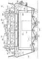
図1〜図9に示す本実施例の調理装置63(揚げ物調理装置)は、次に示す調理炉70と、オイル付着装置110と、加熱装置120と、油きり装置160と、移送装置170と、オイル塗布装置180と、ベルトワイパー190と、ベルト洗浄装置200と、制御装置210とを含み構成されている。
The cooking device 63 (fried food cooking device) of the present embodiment shown in FIGS. 1 to 9 includes a
[調理炉70]
調理炉70は、被調理物Tを調理するための炉であって、支持フレーム65の上に載置された断熱材66の上に載置されている。この調理炉70は、被調理物Tを搬入する搬入口73と搬出する搬出口95とを備えるとともに、その搬入口73から搬出口95にまで水平方向に一直線状に開通した通路Pを備えている。その通路Pの長さ方向に沿って順に、被調理物Tにオイルを付着させるための第1エリアAと、被調理物Tを加熱するための第2エリアBと、被調理物Tの油きりを行うための第3エリアCとを備えている。詳しくは、この調理炉70は、次に示す第1エリアハウジング部71と、第2エリアハウジング部81と、第3エリアハウジング部91とを含み構成されている。
[Cooking furnace 70]
The
第1エリアハウジング部71は、第1エリアAを通路Pの上方及び側方から囲んでおり、その通路Pの上流側の端が、前述の搬入口73となっている。また、この第1エリアハウジング部71の天井部には、第2エリアハウジング部81の入口83から流入した過熱水蒸気を逃がすための排気口76が貫設されており、その上方には、該過熱水蒸気を逃がす方向を横方向(水平方向)に案内するための排気案内部材77が取外し可能に取り付けられている。そして、この第1エリアハウジング部71と第2エリアハウジング部本体81aと後述する第3エリアハウジング部91とで、調理炉本体70aを構成している。
The first
第2エリアハウジング部81は、第2エリアBの上部を通路Pの上方及び側方から囲むとともに分解可能に構成された第2エリアハウジング部本体81aと、第2エリアBの下部を通路Pの下方及び側方から囲むとともに通路Pの長さ方向に直交する方向に引き出し可能に設けられた引出部81b,81bとから構成されている。そして、第2エリアハウジング部本体81aは、その通路Pの上流側の端に、移送装置170で被調理物Tを第1エリアAから搬入するための入口83を備え、通路Pの下流側の端に、移送装置170で被調理物Tを第3エリアCに搬出するための出口85を備えている。そして、入口83には、後述する移送用ベルト175の上面から該入口83の天井部下面までの入口開口高さh1を調節する入口開量調節機構84が設けられ、出口85には、後述する移送用ベルト175の上面から該出口85の天井部下面までの出口開口高さh2を調節する出口開量調節機構86が設けられている。そして、入口開量調節機構84は、入口83の上方に設けられて下端部が該入口83の天井部を構成する入口板84cと、手動で回すための入口開閉ハンドル84aと、該入口開閉ハンドル84aの回転力を上下方向の変位力に変えて入口板84cに伝える動力伝達機構84bとを含み構成されている。また、出口開量調節機構86は、出口85の上方に設けられて下端部が該出口85の天井部を構成する出口板86cと、手動で回すための出口開閉ハンドル86aと、該出口開閉ハンドル86aの回転力を上下方向の変位力に変えて出口板86cに伝える動力伝達機構86bとを含み構成されている。また、第2エリアハウジング部本体81aの内側には、通路Pをその上方及び側方から囲む邪魔板88が設けられるとともに、該邪魔板88を貫通して上下方向に延びて第2エリアBを通路Pの長さ方向に仕切る仕切89が設置されており、それによって、第2エリアハウジング部本体81aと邪魔板88との間の空間が複数の蒸気循環室B2,B2に仕切られるとともに、邪魔板88の内側のエリアも複数の加熱室B1,B1に仕切られている。また、各引出部81bには、該引出部81bを引き出す際に手で掴むための取っ手82,82が取付られている。また、引出部81b,81bの下方には、該引出部81b,81bの引出時に第2エリアハウジング部本体81aから落ちた油や隙間から漏れた油等を受けるためのトレー67,67が載置されている。
The second
第3エリアハウジング部91は、第3エリアCを通路Pの上方及び側方から囲んでおり、その通路Pの下流側の端が、前述の搬出口95となっている。また、この第3エリアハウジング部91の天井部には、第2エリアハウジング部81の出口85から流入した過熱水蒸気を逃がすための排気口96が貫設されており、その上方には、該過熱水蒸気を逃がす方向を横方向(水平方向)に案内するための排気案内部材97が取外し可能に取り付けられている。
The third
[オイル付着装置110]
オイル付着装置110は、第1エリアA内にオイルをミスト状に断続的に噴射することによって被調理物Tにオイルを付着させるための装置である。このオイル付着装置110は、第1エリアハウジング部71の天井部に取り付けられたオイルミスト噴射部材111と、先端部がオイルミスト噴射部材111に接続され、後端部が図示しないオイルタンクに接続されたオイル管115(オイルノズル)と、先端部がオイルミスト噴射部材111に接続され、後端部が図示しないコンプレッサに接続された空気管116(エアーノズル)とを含み構成されている。そして、このオイル付着装置110は、オイル管115(オイルノズル)からオイルミスト噴射部材111に供給する常温(10〜30℃程度)のオイルを、空気管116(エアーノズル)からオイルミスト噴射部材111に供給するエアーの圧力で、該エアーと混合しつつ吹き飛ばすことによって、該オイルミスト噴射部材111から第1エリアA内にオイルをミスト状に噴射する。該オイルをミスト状を噴射するタイミングは、被調理物Tが第1エリアA内の所定位置を通過するタイミングであり、該被調理物Tがきたことは図示しないセンサによって感知する。オイルをミスト状に噴射する時間、噴射する量及びエアーの圧力は、制御装置210による設定次第で、適宜変更できるが、噴射する時間は、0.1〜0.2秒間程度であり、エアーの圧力は、0.2〜0.5MPa程度である。
[Oil adhesion device 110]
The oil adhering device 110 is an apparatus for adhering oil to the object to be cooked T by injecting oil into the first area A intermittently in a mist form. The oil adhering device 110 has an oil
[加熱装置120]
加熱装置120は、第2エリアB内に過熱水蒸気を送るとともに、該過熱水蒸気を加熱室B1,B1と蒸気循環室B2,B2とで対流させることによって、被調理物Tを加熱する装置である。この加熱装置120は、次に示す蒸気供給装置121と、蒸気対流装置151,151とを含み構成されている。
[Heating device 120]
The
[蒸気供給装置121]
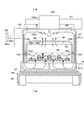
蒸気供給装置121は、第2エリアBに過熱水蒸気を供給するための装置である。この蒸気供給装置121が供給する過熱水蒸気の温度及び流量は、制御装置210による設定次第で適宜変更できる。この蒸気供給装置121は、次に示す蒸気管122と、蒸気タンク125(及びその周辺機器126,127,128)と、水圧管132(及びその周辺機器133,134)と、水タンク135(及びその周辺機器136,137,138)と、給水管142(及びその周辺機器144)とを含み構成されている。
[Steam supply device 121]
The
蒸気管122は、蒸発タンク125内に発生した過熱水蒸気を第2エリアBに流す管である。この蒸気管122の後端部は蒸気タンク125に接続され、先端部は第2エリアハウジング部本体81a(蒸気循環室B2,B2)の天井部に接続されている。
The
蒸気タンク125は、その底部に水を貯めるとともにその上方に過熱水蒸気を発生させるためのタンクである。この蒸気タンク125に対しては、その底部の水を加熱してタンク内に過熱水蒸気を発生させる蒸発装置128と、水量が所定の基準水量M以上あるか否かを検出するための基準水量センサ126と、水量が所定の最少限水量N以上あるか否か否かを検出する最少限水量センサ127とが設けられている。この蒸気タンク125内の過熱水蒸気の気圧及び温度は、制御装置210による設定次第で適宜変更できるが、気圧は0.3〜0.4MPa程度であり、温度は105〜150℃程度である。
The
水圧管132は、水タンク135内の水を蒸気タンク125内に流す管である。この水圧管132の後端部は水タンク135に接続され、先端部は蒸気タンク125に接続されている。また、この水圧管132の中間部には、水タンク135側の水圧が蒸気タンク125側の水圧よりも大きくなった際には弁を開き、水タンク135側の水圧が蒸気タンク125側の水圧よりも小さくなった際には弁を閉じる水圧管逆止弁133と、制御装置210によって開閉制御される水圧管電磁弁134とが設けられている。そして、それらの水圧管逆止弁133と水圧管電磁弁134とが、蒸気タンク125内の水が水圧管132に逆流するのを防止する逆流防止機構133,134を構成している。なお、このように水圧管電磁弁134に加えて水圧管逆止弁133をも設けているのは、より確実に逆流を防止するためである。
The
水タンク135は、蒸気タンク125に供給する水を貯めるためのタンクである。この水タンク135に対しては、エアーの圧力で該水タンク135内の水圧を蒸気タンク125内の水圧よりも高く加圧するコンプレッサ138が空気管139を介して接続されるとともに、水量が所定の下限水量L以上あるか否かを検出する下限センサ137と、水量が所定の上限水量H以上あるか否かを検出する上限センサ136とが設けられている。この水タンク135内のエアーの気圧は、制御装置210による設定次第で適宜変更できるが、0.3〜0.6MPa程度である。
The
給水管142は、水タンク135内に水を供給する管である。この給水管142の後端部は給水源(蛇口等)に接続され、先端部は水タンク135に接続されている。そして、この給水管142の中間部には、制御装置210によって開閉制御される給水管電磁弁144が設けられている。
The
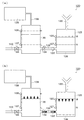
次に、制御装置210による制御に基づいて蒸気タンク125内に水を供給する際の手順を説明する。まず、図6(a)に示すように、基準水量センサ126で蒸発タンク125内の水量が基準水量Mを下回ったと検知した際には、図6(b)に示すように、水圧管電磁弁134を開いて、水タンク135内の水を蒸気タンク125内に流入させる。そして、基準水量センサ126で蒸気タンク125内の水量が基準水量Mに達したと検知した際には、水圧管電磁弁134を閉じて水の供給を停止する。よって、蒸発タンク125内の水量は、常に、基準水量M付近に保たれる。また、万が一にも最少限水量センサ127で蒸気タンク125内の水量が最少限水量Nを下回ったと検知した際には、調理装置63全体の運転を緊急停止する。
Next, a procedure for supplying water into the
次に、制御装置210による制御に基づいて水タンク135内に水を供給する際の手順を説明する。まず、図7(a)に示すように、下限センサ137で水タンク135内の水量が下限水量Lを下回ったと検知した際には、図7(b)に示すように、水圧管電磁弁134を閉じるとともに、コンプレッサ138による加圧を停止して水タンク135内の水圧を減圧してから、給水管電磁弁144を開いて水タンク135内に水を供給する。そして、上限センサ136で水タンク135内の水量が上限水量Hに達したと検知した際には、給水管電磁弁144を閉じて水の供給を停止するとともに、コンプレッサ138による加圧を再開する。
Next, a procedure for supplying water into the
[蒸気対流装置151,151]
蒸気対流装置151,151は、第2エリアB内に供給された過熱水蒸気を加熱室B1,B1と蒸気循環室B2,B2とで対流させるための装置であって、各蒸気循環室B2,B2毎に1つずつ設けられている。各蒸気対流装置151は、加熱室B1内の空気及び過熱水蒸気を蒸気循環室B2内に流入させるための流入孔152と、蒸気循環室B2内に流入させた空気及び過熱水蒸気を加熱室B1内に流出させるための複数の流出孔153,153・・と、加熱室B1内の空気及び過熱水蒸気を流入孔152から水蒸気循環室B2内に流入させるため送風機155と、過熱水蒸気の温度を調節するためのヒータ158とを含み構成されている。
[
The
詳しくは、流入孔152は、邪魔板88の天井部に貫設されている。また、複数の流出孔153,153・・は、上側の流出孔153,153と、それよりも下方に設けられた流出孔153,153,153とを含み構成されている。そして、上側の流出孔153,153は、邪魔板88の両側の側壁部に、通路Pの長さ方向に並べて貫設されている。また、下側の流出孔153,153,153は、邪魔板88の両側の側壁部における上側の流出孔153,153よりも下方に、該上側の流出孔153,153の真下に重ならないように通路Pの長さ方向にそれぞれずらして、該通路Pの長さ方向に並べて貫設されている。そして、各下側の流出孔153には、該流出孔153に蒸気循環室B2内の空気及び過熱水蒸気を案内するためのガイド154が設けられている。また、送風機155は、蒸気循環室B2内における流入孔152の真上に設置されたフィン155aと、該フィン155aを回転駆動する、第2エリアハウジング部本体81aの天井部の上に設置されたモータ155bとを含み構成されている。また、ヒータ158は、蒸気循環室B2内における第2エリアハウジング部本体81aの内側面と、邪魔板88の外側面との間に設けられている。各蒸気循環室B2,B2内におけるフィン155a,155aの回転速度及びヒータ158,158・・の発熱量は、制御装置210による設定次第で、各蒸気対流装置151,151毎に適宜変更することができる。
Specifically, the
[油きり装置160]
油きり装置160は、第3エリアC内に冷水をミスト状に断続的に噴射することによって被調理物Tの表面からオイルを飛ばすための装置である。この油きり装置160は、第3エリアハウジング部91の天井部に取り付けられた冷水ミスト噴射部材161と、先端部が冷水ミスト噴射部材161に接続され、後端部が図示しない冷水タンクに接続された冷水管165(冷水ノズル)と、先端部が冷水ミスト噴射部材161に接続され、後端部が図示しないコンプレッサに接続された空気管166(エアーノズル)とを含み構成されている。そして、この油きり装置160は、冷水管165(冷水ノズル)から冷水ミスト噴射部材161に供給する常温(10〜30℃程度)の冷水を、空気管166(エアーノズル)から冷水ミスト噴射部材161に供給するエアーの圧力で、該エアーと混合しつつ吹き飛ばすことによって、該冷水ミスト噴射部材161から冷水を第3エリアC内にミスト状に噴射する。該冷水をミスト状に噴射するタイミングは、被調理物Tが第3エリアC内の所定位置を通過するタイミングであり、該被調理物Tがきたことは図示しないセンサによって感知する。冷水をミスト状を噴射する時間、噴射する量及びエアーの圧力は、制御装置210による設定次第で、適宜変更できるが、噴射する時間は、0.1〜0.2秒間程度であり、エアーの圧力は、0.2〜0.5MPa程度である。
[Oil drilling device 160]
The oil drilling device 160 is a device for spraying oil from the surface of the article to be cooked T by spraying cold water into the third area C intermittently in a mist form. The oil draining device 160 has a cold water
[移送装置170]
移送装置170は、被調理物Tを通路Pに沿って第1エリアA、第2エリアB、第3エリアCの順に移送するための装置である。この移送装置170は、次に示すベルト支持機構171と、移送用ベルト175と、ベルト駆動装置とを含み構成されている。
[Transfer device 170]
The
ベルト支持機構171は、移送用ベルト175を環状に支持するための機構である。このベルト支持機構171は、調理炉70よりも通路Pの一方及び他方の長さ方向側にそれぞれ1対ずつ設けられた2対のスプロケット172−172,172−172と、調理炉70よりも下方に設けられた複数個のローラ173,173・・とからなる。
The
移送用ベルト175は、被調理物Tを搬入口73から第1エリアA、第2エリアB、第3エリアCを通過させて搬出口95にまで移送するための網状のベルトであって、ベルト支持機構171によって次に示す環状に支持されている。すなわち、この移送用ベルト175は、搬入口73から通路Pを通過して搬出口95にまで延びる移送部175aと、該移送部175aの搬出口95側の端から調理炉70の下方を通過して移送部175aの搬入口73側の端に繋がる戻り部175bとからなるとともに、戻り部175bの中間部には下方に突出する第1突出部175xと第2突出部175yとが形成される環状に架けられている。
The
駆動装置(図示略)は、一対のスプロケット172−172を回転駆動することによって、移送用ベルト175を駆動する装置であって、動力源となるモータ(図示略)と、その動力を1対のスプロケット172−172に伝える動力伝達機構(図示略)とを含み構成されている。この駆動装置(図示略)で1対のスプロケット172−172を回転駆動する速さは、制御装置210による設定次第で適宜変更することができるが、被調理物Tが調理炉70を通過するのにかかる時間は3〜30分程度である。
The drive device (not shown) is a device that drives the
[オイル塗布装置180]
オイル塗布装置180は、移送用ベルト175に被調理物Tが焦げ付かないように該移送用ベルト175にオイルを塗るための装置である。このオイル塗布装置180は、次に示すオイル槽182と、オイル塗布ローラ184と、ローラ移動装置185とを含み構成されている。
[Oil application device 180]
The
オイル槽182は、オイルを貯めるための移送用ベルト175の幅方向に延びる上方に開口した槽であって、支持フレーム65に取り付けられたオイル塗布装置フレーム181に対して水平方向に変位可能に取り付けられている。また、オイル塗布ローラ184は、オイル槽182のオイルUを移送用ベルト175に塗布するための該移送用ベルト175の幅方向に延びるローラであって、オイル槽182の両端に突設されて上方に突出したローラ支持フレーム183,183に回転可能に支持されている。このオイル塗布ローラ184は、下部が該オイル槽182のオイルUに浸かるとともに、使用位置に配された際には、該下部よりも上方の部分が移送用ベルト175に当接して該移送用ベルト175が駆動されるのに従い回転する。また、ローラ移動装置185は、オイル槽182をオイル塗布装置フレーム181に対して水平方向に変位させることによって、オイル塗布ローラ184を前述の使用位置と移送用ベルト175に当接しない不使用位置との間で駆動する装置であって、オイル塗布装置フレーム181に固着されている。
The
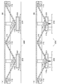
そして、移送用ベルト175にオイルを塗布する必要のある調理(焦げ付き易い調理)をする際には、図8(a)に示すように、制御装置210による制御に基づきローラ移動装置185でオイル塗布ローラ184を使用位置に移動させる。その一方、移送用ベルト175にオイルを塗布する必要のない調理(焦げ付き難い調理)をする際には、図8(b)に示すように、制御装置210による制御に基づきローラ移動装置185でオイル塗布ローラ184を不使用位置に移動させる。
Then, when cooking (cooking that is easily burnt) that requires application of oil to the
[ベルトワイパー190]
ベルトワイパー190は、移送用ベルト175に塗布したオイルや付着した被調理物Tの粕などを拭き取るための部材であって、次に示す拭布193と、布押圧部材194とを含み構成されている。
[Belt Wiper 190]
The
拭布193は、移送用ベルト175を拭くための該移送用ベルトの幅方向に延びる布であって、支持フレーム65に取り付けられたベルトワイパーフレーム191に貫設された取付孔192,192に取り付けられてる。また、布押圧部材194は、取付孔192,192に取り付けられた拭布193を弾性力で移送用ベルト175に押圧するための弾性部材であって、ベルトワイパーフレーム191に固着されている。
The wiping
[ベルト洗浄装置200]
ベルト洗浄装置200は、移送用ベルト175の第1突出部175xの下方に設けられて上方に開口した、洗浄液Xを入れる洗浄槽201と、該洗浄槽201をエアーの圧力で昇降させる洗浄槽昇降装置202(エアーシリンダ)と、移送用ベルト175の第2突出部175yの下方に設けられて上方に開口した、濯ぎ水Yを入れる濯ぎ槽205と、該濯ぎ槽205をエアーの圧力で昇降させる濯ぎ槽昇降装置206(エアーシリンダ)とを含み構成されている。
[Belt cleaning device 200]
The
次に、制御装置210による制御に基づいて、該ベルト洗浄装置200で移送用ベルト175を洗浄する際の様子を以下に説明する。
Next, how the
まず、図9(a)に示すように、洗浄槽201及び濯ぎ槽205を下げた状態から、図9(b)に示すように、洗浄槽201を洗浄槽昇降装置202で上昇させて第1突出部175xを洗浄液Xに浸けるとともに、濯ぎ槽205を濯ぎ槽昇降装置206で上昇させて第2突出部175yを濯ぎ水Yに浸ける。また、加熱装置120を稼動させて第2エリアB内に過熱水蒸気を対流させる。そして、その状態のまま、移送用ベルト175をベルト駆動装置(図示略)で駆動して数週(3週くらい)回すことにより、該移送用ベルト175の各部を暖めながら洗浄し濯ぐ。そして、洗浄終了後は、洗浄槽201を洗浄槽昇降装置202で降下させて第1突出部175xを洗浄液Xから退出させるとともに、濯ぎ槽205を濯ぎ槽昇降装置206で降下させて第2突出部175yを濯ぎ水Yから退出させる。
First, as shown in FIG. 9A, the
なお、以上では、洗浄槽201と濯ぎ槽205とを同時に上昇させる場合を示したが、場合によっては、まずは、洗浄槽201のみを上昇させるとともに移送用ベルト175を回すことにより該移送用ベルト175を洗浄し、次に、洗浄槽201を下降させ濯ぎ槽205を上昇させるとともに移送用ベルト175を回すことにより該移送用ベルト175を濯ぐようにしてもよい。
In the above, the case where the
[制御装置210]
制御装置210は、オイル付着装置110、加熱装置120(蒸気供給装置121及び蒸気対流装置151)、油きり装置160、移送装置170、オイル塗布装置180及びベルト洗浄装置200を制御する装置(コンピュータ)であって、それらの各装置110,120(121,151),160,170,180,200の一部を構成している。この制御装置210は、入力された調理プログラムに従い各装置を制御して調理を行う。また、この制御装置210は、一度入力された調理プログラムを記憶し、該調理プログラムが選択されれば即座に再現できるように構成されている。また、この制御装置210には、決められた時間に加熱装置120の運転を開始して、調理炉70内の第2エリアBを予め暖めておくためのスタートタイマーが設けられている。
[Control device 210]
The
以上に示した調理装置63を用いて実際に被調理物Tを調理する際のようすを{1}被調理物Tの搬入、{2}オイルミストによるオイルの付着、{3}過熱水蒸気による加熱、{4}冷水ミストによる油きり、{5}被調理物Tの搬出 の順に以下に説明する。
Using the
{1}被調理物Tの搬入
調理炉70よりも移送方向の上流側(搬入口73の外)において、作業者が、紛材を塗した被調理物Tを、移送用ベルト175の上面に載置する。
{1} Carrying Into-be-Cooked T On the upper side of the
{2}オイルミストによるオイルの付着
次に、被調理物Tが移送装置170によって第1エリアAに移送される。そして、図示しないセンサにより被調理物Tが感知されると、オイル付着装置110からオイルがミスト状に噴射され、それによって、被調理物Tの表面にオイルが付着する。
{2} Attachment of oil by oil mist Next, the to-be-cooked object T is transferred to the first area A by the
{3}過熱水蒸気による加熱
次に、被調理物Tが移送装置170によって第2エリアBに移送される。ここで、加熱装置120により送り込まれる過熱水蒸気熱風により、被調理物Tが芯まで加熱されるとともに、被調理物Tの表面に付着しているオイルが加熱させられることにより該表面が揚げられる。
{3} Heating with Superheated Steam Next, the object to be cooked T is transferred to the second area B by the
{4}冷水ミストによる油きり
次に、被調理物Tが移送装置170によって第3エリアCに移送される。そして、図示しないセンサにより被調理物Tが感知されると、油きり装置160から冷水がミスト状に噴射され、それによって、被調理物Tの表面からオイルが飛ばされる。
{4} Oil draining with cold water mist Next, the object to be cooked T is transferred to the third area C by the
{5}被調理物の搬出
次に、被調理物Tは移送装置170によって調理炉70よりも移送方向の下流側(搬出口95の外)に移送され、ここで、作業者が、被調理物Tを回収する。
{5} Unloading of cooked food Next, the cooked food T is transferred by the
本実施例によれば、次の[A]〜[N]の効果を得ることができる。
[A]オイルをミスト状に噴射することによって被調理物Tの表面にオイルを効率よく行き渡らせるとともに、被調理物T及びその表面のオイルを過熱水蒸気で加熱することにより、少量のオイルで効率よく被調理物Tを揚げることができる。そのため、揚げ物独特の油による旨みを失わせることもなく、オイルの使用量を抑えることができる。そのため、健康的で、美味しく、かつ、環境によい食品を提供することができる。
[B]従来のように高温のオイルに被調理物を投入することがないため、投入の度にオイルの温度が下がってしまうという問題が解消される。そのため、温度変化によるオイルの劣化が起こり難く、より旨みを引き出すことができる。また、更に、劣化した古いオイルも発生しないため、該古いオイルの廃棄処分も不要となる。
[C]過熱水蒸気で加熱するため、旨みを被調理物T内に閉じ込めることができる。
[D]加熱装置120は、邪魔板88は下方に開口しており、また、該邪魔板88の側面には流出孔153,153・・が設けられているため、被調理物Tを上下均等に加熱することができる。
[E]冷水をミスト状に噴射して被調理物Tの表面からオイルを飛ばすので、オイル独特のギラギラ感、ベトベト感をなくし、より旨みを引き出すことができる。
[F]移送装置170を備えているので、被調理物Tを自動で、かつ、連続して揚げることができる。また、このように自動で、かつ、連続的に揚げるため、仕上がりの状態が略均一になり、品質が安定する。
[G]揚げ物の調理のみならず、オイル付着装置110や油きり装置160を休止させて使用した場合には、炊き物、煮物、蒸し物、焼き物等の調理にも使用することができる。
According to the present embodiment, the following effects [A] to [N] can be obtained.
[A] The oil is efficiently spread over the surface of the object to be cooked T by jetting the oil in a mist form, and the oil to be cooked and the oil on the surface are heated with superheated steam, so that it is efficient with a small amount of oil. The to-be-cooked object T can be fried well. Therefore, the amount of oil used can be suppressed without losing the umami due to the oil unique to deep-fried food. Therefore, it is possible to provide a food that is healthy, delicious, and environmentally friendly.
[B] Since the object to be cooked is not put into high-temperature oil as in the prior art, the problem that the temperature of the oil is lowered every time it is put in is solved. Therefore, the deterioration of the oil due to the temperature change hardly occurs, and the umami can be extracted more. Furthermore, since no deteriorated old oil is generated, it is not necessary to dispose of the old oil.
[C] Since it is heated with superheated steam, the umami can be confined in the cooking object T.
[D] In the
[E] Since cold oil is sprayed in the form of a mist and the oil is blown off from the surface of the object to be cooked T, the glaring and sticky feeling peculiar to the oil can be eliminated and the umami can be further extracted.
[F] Since the
[G] In addition to cooking fried foods, when the oil adhering device 110 and the oil drilling device 160 are used after being stopped, they can be used for cooking cooked food, boiled food, steamed food, grilled food, and the like.
[H]第2エリアハウジング部81の引出部81b,81bは引き出し可能になっているため、該第2エリアBの清掃が簡単である。また、第2エリアハウジング部本体81aも分解可能に構成されているため、この点でも第2エリアBの清掃が簡単である。
[I]第2エリアハウジング部81の入口83及び出口85には、それぞれ入口開量調節機構84及び出口開量調節機構86がついているため、それらで入口83及び出口85を被調理物Tが通り得る必要最小限にまで小さく閉じることにより、第2エリアB内の保温性を高めることができる。
[J]第1エリアハウジング部71及び第3エリアハウジング部91には、排気口76,96が設けられているため、第2エリアハウジング部81の入口83から第1エリアハウジング部71に流入した過熱水蒸気、及び第2エリアハウジング部81の出口85から第3エリアハウジング部91に流入した過熱水蒸気を素早く排気することができる。
[K]水タンク135内の水圧を蒸気タンク125内の水圧よりも高く加圧するコンプレッサ138を備えているため、蒸気タンク125内に高温の過熱水蒸気を発生させることにより該蒸気タンク125内が高圧になった場合にも、該蒸気タンク125内に水を問題なく供給することができる。また、その際の加圧方法も、コンプレッサ138によるエアーの圧力での加圧であるため、スクリューポンプで加圧する場合よりも効率的であり、また、コストも低く抑えることができる。
[L]オイル塗布装置180があるため、移送用ベルト175にオイルを簡単に塗布することができる。
[M]ベルトワイパー190があるため、移送用ベルト175を簡単に拭くことができる。
[N]ベルト洗浄装置200があるため、移送用ベルト175を簡単に洗浄することができる。
[H] Since the pull-out
[I] The
[J] Since the first
[K] Since the
[L] Since the
[M] Since the
[N] Since there is the
なお、本発明は上記実施例に限定されるものではなく、発明の趣旨を逸脱しない範囲で各部の構成や形状を任意に変更して実施することもできる。 In addition, this invention is not limited to the said Example, It can also implement by changing arbitrarily the structure and shape of each part in the range which does not deviate from the meaning of invention.
63 調理装置
70 調理炉
121 蒸気供給装置
122 蒸気管
125 蒸気タンク
126 基準水量センサ
128 蒸発装置
132 水圧管
133 水圧管逆止弁(逆流防止機構)
134 水圧管電磁弁(逆流防止機構)
135 水タンク
136 上限センサ
137 下限センサ
138 コンプレッサ
142 給水管
144 給水管電磁弁
210 制御装置
M 基準水量
H 上限水量
L 下限水量
63
134 Water pressure solenoid valve (Backflow prevention mechanism)
135
Claims (6)
前記蒸気供給装置(121)は、底部に水を貯える蒸気タンク(125)と、該底部の水を加熱して該蒸気タンク(125)内に過熱水蒸気を発生させる蒸発装置(128)と、前記蒸気タンク(125)内に発生した過熱水蒸気を前記調理炉(70)に流す蒸気管(122)と、
水を貯える水タンク(135)と、該水タンク(135)内の水圧をエアーの圧力で前記蒸気タンク(125)内の水圧よりも高く加圧するコンプレッサ(138)と、該水タンク(135)内の水を前記蒸気タンク(125)内に流す水圧管(132)とを備えたことを特徴とする調理装置。 In a cooking device (63) comprising a cooking furnace (70) and a steam supply device (121) for supplying superheated steam at 100 ° C. or higher to the cooking furnace (70),
The steam supply device (121) includes a steam tank (125) for storing water at the bottom, an evaporator (128) for heating the water at the bottom to generate superheated steam in the steam tank (125), A steam pipe (122) for flowing superheated steam generated in the steam tank (125) to the cooking furnace (70);
A water tank (135) for storing water, a compressor (138) for pressurizing the water pressure in the water tank (135) to be higher than the water pressure in the steam tank (125) by air pressure, and the water tank (135) A cooking apparatus comprising: a water pressure pipe (132) for flowing water inside the steam tank (125).
前記基準水量センサ(126)で前記蒸気タンク(125)内の水量が前記基準水量(M)を下回ったと検知した際には前記水圧管電磁弁(134)を開き、前記基準水量センサ(126)で前記蒸気タンク(125)の水量が前記基準水量(M)に達したと検知した際には前記水圧管電磁弁(134)を閉じる制御装置(210)とを備えた請求項1に記載の調理装置。 The steam supply device (121) opens and closes a reference water amount sensor (126) that detects whether or not the amount of water in the steam tank (125) is equal to or greater than a predetermined reference water amount (M), and the water pressure pipe (132). A hydraulic pipe solenoid valve (134) to perform,
When the reference water amount sensor (126) detects that the water amount in the steam tank (125) is lower than the reference water amount (M), the water pressure pipe solenoid valve (134) is opened, and the reference water amount sensor (126) is opened. The control device (210) according to claim 1, further comprising a control device (210) for closing the water pressure pipe solenoid valve (134) when it is detected that the amount of water in the steam tank (125) has reached the reference water amount (M). Cooking equipment.
前記下限センサ(137)で前記水タンク(135)内の水量が前記下限水量(L)を下回ったと検知した際には、前記コンプレッサ(138)による加圧を止めて前記水タンク(135)内を減圧するとともに前記給水管電磁弁(144)を開いて前記水タンク(135)内に水を供給する制御装置(210)とを備えた請求項1又は2記載の調理装置。 The steam supply device (121) includes a lower limit sensor (137) for detecting whether or not the amount of water in the water tank (135) is equal to or greater than a predetermined lower limit amount of water (L), and water in the water tank (135). A water supply pipe (142) for supplying water, a water supply solenoid valve (144) for opening and closing the water supply pipe (142), and preventing water in the steam tank (125) from flowing back to the water pressure pipe (132) A backflow prevention mechanism (133, 134),
When the lower limit sensor (137) detects that the amount of water in the water tank (135) has fallen below the lower limit amount of water (L), the pressurization by the compressor (138) is stopped and the water tank (135) The cooking device according to claim 1, further comprising: a control device (210) that decompresses the water supply pipe and opens the water supply solenoid valve (144) to supply water into the water tank (135).
前記制御装置(210)は、前記上限センサ(136)で前記水タンク(135)内の水量が前記上限水量(H)に達したと検知した際には、前記給水管電磁弁(144)を閉じるとともに前記コンプレッサ(138)による加圧を再開する請求項3に記載の調理装置。 The steam supply device (121) includes an upper limit sensor (136) that detects whether or not the amount of water in the water tank (135) is equal to or greater than a predetermined upper limit amount of water (H).
When the upper limit sensor (136) detects that the amount of water in the water tank (135) has reached the upper limit amount of water (H), the control device (210) controls the water supply solenoid valve (144). The cooking apparatus according to claim 3, wherein the pressurization by the compressor (138) is resumed while closing.
Priority Applications (1)
| Application Number | Priority Date | Filing Date | Title |
|---|---|---|---|
| JP2010267759A JP2012117747A (en) | 2010-11-30 | 2010-11-30 | Cooking device |
Applications Claiming Priority (1)
| Application Number | Priority Date | Filing Date | Title |
|---|---|---|---|
| JP2010267759A JP2012117747A (en) | 2010-11-30 | 2010-11-30 | Cooking device |
Publications (1)
| Publication Number | Publication Date |
|---|---|
| JP2012117747A true JP2012117747A (en) | 2012-06-21 |
Family
ID=46500793
Family Applications (1)
| Application Number | Title | Priority Date | Filing Date |
|---|---|---|---|
| JP2010267759A Pending JP2012117747A (en) | 2010-11-30 | 2010-11-30 | Cooking device |
Country Status (1)
| Country | Link |
|---|---|
| JP (1) | JP2012117747A (en) |
-
2010
- 2010-11-30 JP JP2010267759A patent/JP2012117747A/en active Pending
Similar Documents
| Publication | Publication Date | Title |
|---|---|---|
| JP6297190B2 (en) | Boiled noodle machine | |
| EP3884820B1 (en) | Air fryer with steaming function and method for controlling air fryer with steaming function | |
| KR100629336B1 (en) | Steam generator in steam oven | |
| US20170245683A1 (en) | Apparatus and method for preparing food | |
| EP3134683B1 (en) | Oven with steam-water separation and method of using said oven | |
| JP2017094107A (en) | Automatic coffee drip device | |
| EP3777556B1 (en) | Installation for defrosting or tempering of frozen food products | |
| JP2010041995A (en) | Steam-charging type conveyor oven | |
| US11112122B2 (en) | System comprising a self-cleaning oven, and method for cleaning a self-cleaning oven | |
| KR101296777B1 (en) | Clean water storage tank with a steam convection oven | |
| KR20090079560A (en) | Laundry equipment with steam generator | |
| JP2011200735A (en) | Cooker | |
| KR101698692B1 (en) | Dish washer having a function of preheating rinse water and air spray | |
| JP2018015047A (en) | Rice cooking method | |
| JP6111619B2 (en) | Bathtub cleaning equipment | |
| JP3858671B2 (en) | rice cooker | |
| JP6131209B2 (en) | Boiled noodle machine | |
| JP2012115467A (en) | Cooking device | |
| KR101619080B1 (en) | Steam cooker | |
| CN112471880B (en) | Cooking pot with multiple functions | |
| JP2012117747A (en) | Cooking device | |
| KR101178565B1 (en) | Apparatus for injecting smoke screen for agicultural use | |
| JP2011149687A (en) | Device and method for cooking fried food | |
| JP2016140677A (en) | Cleaning device | |
| JP5064325B2 (en) | Steam cooker |