JP2012117802A - 熱交換器 - Google Patents
熱交換器 Download PDFInfo
- Publication number
- JP2012117802A JP2012117802A JP2011233083A JP2011233083A JP2012117802A JP 2012117802 A JP2012117802 A JP 2012117802A JP 2011233083 A JP2011233083 A JP 2011233083A JP 2011233083 A JP2011233083 A JP 2011233083A JP 2012117802 A JP2012117802 A JP 2012117802A
- Authority
- JP
- Japan
- Prior art keywords
- tube
- refrigerant
- fluid
- cooling medium
- heat exchanger
- Prior art date
- Legal status (The legal status is an assumption and is not a legal conclusion. Google has not performed a legal analysis and makes no representation as to the accuracy of the status listed.)
- Granted
Links
- 239000003507 refrigerant Substances 0.000 claims abstract description 594
- 239000012530 fluid Substances 0.000 claims abstract description 247
- 238000011144 upstream manufacturing Methods 0.000 claims description 175
- 238000009826 distribution Methods 0.000 claims description 29
- 238000005452 bending Methods 0.000 claims description 7
- 238000012546 transfer Methods 0.000 claims description 4
- 238000003475 lamination Methods 0.000 claims description 2
- 230000003313 weakening effect Effects 0.000 claims description 2
- 239000002826 coolant Substances 0.000 abstract description 389
- 239000000498 cooling water Substances 0.000 abstract description 154
- 238000001816 cooling Methods 0.000 abstract description 41
- 230000037361 pathway Effects 0.000 abstract 1
- 238000010438 heat treatment Methods 0.000 description 42
- 238000004378 air conditioning Methods 0.000 description 39
- 239000002918 waste heat Substances 0.000 description 21
- 238000010257 thawing Methods 0.000 description 15
- 238000011084 recovery Methods 0.000 description 13
- 238000007664 blowing Methods 0.000 description 12
- 238000010586 diagram Methods 0.000 description 11
- 238000004891 communication Methods 0.000 description 10
- 230000008859 change Effects 0.000 description 8
- 239000002131 composite material Substances 0.000 description 8
- 239000000203 mixture Substances 0.000 description 8
- 238000005192 partition Methods 0.000 description 8
- 230000005855 radiation Effects 0.000 description 8
- 238000005304 joining Methods 0.000 description 6
- 238000005057 refrigeration Methods 0.000 description 6
- 230000015572 biosynthetic process Effects 0.000 description 5
- 230000006835 compression Effects 0.000 description 5
- 238000007906 compression Methods 0.000 description 5
- 238000001514 detection method Methods 0.000 description 5
- 239000007788 liquid Substances 0.000 description 5
- 230000007246 mechanism Effects 0.000 description 5
- 229910052751 metal Inorganic materials 0.000 description 5
- 239000002184 metal Substances 0.000 description 5
- 238000000034 method Methods 0.000 description 5
- 239000012071 phase Substances 0.000 description 5
- 230000000704 physical effect Effects 0.000 description 5
- 210000000078 claw Anatomy 0.000 description 4
- 230000001143 conditioned effect Effects 0.000 description 4
- 230000002093 peripheral effect Effects 0.000 description 4
- 230000008569 process Effects 0.000 description 4
- LYCAIKOWRPUZTN-UHFFFAOYSA-N Ethylene glycol Chemical compound OCCO LYCAIKOWRPUZTN-UHFFFAOYSA-N 0.000 description 3
- 238000005219 brazing Methods 0.000 description 3
- 238000001704 evaporation Methods 0.000 description 3
- 239000007789 gas Substances 0.000 description 3
- 239000007791 liquid phase Substances 0.000 description 3
- 239000000463 material Substances 0.000 description 3
- 238000002156 mixing Methods 0.000 description 3
- 230000000149 penetrating effect Effects 0.000 description 3
- 238000012545 processing Methods 0.000 description 3
- 229910000838 Al alloy Inorganic materials 0.000 description 2
- CURLTUGMZLYLDI-UHFFFAOYSA-N Carbon dioxide Chemical compound O=C=O CURLTUGMZLYLDI-UHFFFAOYSA-N 0.000 description 2
- 239000000470 constituent Substances 0.000 description 2
- 230000003247 decreasing effect Effects 0.000 description 2
- 230000008020 evaporation Effects 0.000 description 2
- 230000012447 hatching Effects 0.000 description 2
- 239000010721 machine oil Substances 0.000 description 2
- 239000003921 oil Substances 0.000 description 2
- 239000011232 storage material Substances 0.000 description 2
- OKTJSMMVPCPJKN-UHFFFAOYSA-N Carbon Chemical compound [C] OKTJSMMVPCPJKN-UHFFFAOYSA-N 0.000 description 1
- 239000004215 Carbon black (E152) Substances 0.000 description 1
- 239000004743 Polypropylene Substances 0.000 description 1
- 238000010521 absorption reaction Methods 0.000 description 1
- 230000009471 action Effects 0.000 description 1
- 238000013459 approach Methods 0.000 description 1
- 239000007864 aqueous solution Substances 0.000 description 1
- 238000004364 calculation method Methods 0.000 description 1
- 229910002092 carbon dioxide Inorganic materials 0.000 description 1
- 239000001569 carbon dioxide Substances 0.000 description 1
- 239000002041 carbon nanotube Substances 0.000 description 1
- 229910021393 carbon nanotube Inorganic materials 0.000 description 1
- 239000003795 chemical substances by application Substances 0.000 description 1
- KYKAJFCTULSVSH-UHFFFAOYSA-N chloro(fluoro)methane Chemical compound F[C]Cl KYKAJFCTULSVSH-UHFFFAOYSA-N 0.000 description 1
- 238000002485 combustion reaction Methods 0.000 description 1
- 150000001875 compounds Chemical class 0.000 description 1
- 230000006837 decompression Effects 0.000 description 1
- 230000007423 decrease Effects 0.000 description 1
- 238000009795 derivation Methods 0.000 description 1
- 239000010432 diamond Substances 0.000 description 1
- 230000000694 effects Effects 0.000 description 1
- 238000001125 extrusion Methods 0.000 description 1
- 239000005357 flat glass Substances 0.000 description 1
- 239000000446 fuel Substances 0.000 description 1
- 230000020169 heat generation Effects 0.000 description 1
- 238000005338 heat storage Methods 0.000 description 1
- 229930195733 hydrocarbon Natural products 0.000 description 1
- 150000002430 hydrocarbons Chemical class 0.000 description 1
- 238000010030 laminating Methods 0.000 description 1
- 230000001050 lubricating effect Effects 0.000 description 1
- 239000010687 lubricating oil Substances 0.000 description 1
- 238000004519 manufacturing process Methods 0.000 description 1
- 238000002844 melting Methods 0.000 description 1
- 230000008018 melting Effects 0.000 description 1
- 239000007769 metal material Substances 0.000 description 1
- 238000013021 overheating Methods 0.000 description 1
- -1 polypropylene Polymers 0.000 description 1
- 229920001155 polypropylene Polymers 0.000 description 1
- 238000003825 pressing Methods 0.000 description 1
- 230000009467 reduction Effects 0.000 description 1
- 239000011347 resin Substances 0.000 description 1
- 229920005989 resin Polymers 0.000 description 1
- 238000000926 separation method Methods 0.000 description 1
- 238000003860 storage Methods 0.000 description 1
- 238000010792 warming Methods 0.000 description 1
Images


Classifications
-
- F—MECHANICAL ENGINEERING; LIGHTING; HEATING; WEAPONS; BLASTING
- F28—HEAT EXCHANGE IN GENERAL
- F28D—HEAT-EXCHANGE APPARATUS, NOT PROVIDED FOR IN ANOTHER SUBCLASS, IN WHICH THE HEAT-EXCHANGE MEDIA DO NOT COME INTO DIRECT CONTACT
- F28D7/00—Heat-exchange apparatus having stationary tubular conduit assemblies for both heat-exchange media, the media being in contact with different sides of a conduit wall
- F28D7/16—Heat-exchange apparatus having stationary tubular conduit assemblies for both heat-exchange media, the media being in contact with different sides of a conduit wall the conduits being arranged in parallel spaced relation
-
- F—MECHANICAL ENGINEERING; LIGHTING; HEATING; WEAPONS; BLASTING
- F28—HEAT EXCHANGE IN GENERAL
- F28D—HEAT-EXCHANGE APPARATUS, NOT PROVIDED FOR IN ANOTHER SUBCLASS, IN WHICH THE HEAT-EXCHANGE MEDIA DO NOT COME INTO DIRECT CONTACT
- F28D1/00—Heat-exchange apparatus having stationary conduit assemblies for one heat-exchange medium only, the media being in contact with different sides of the conduit wall, in which the other heat-exchange medium is a large body of fluid, e.g. domestic or motor car radiators
- F28D1/02—Heat-exchange apparatus having stationary conduit assemblies for one heat-exchange medium only, the media being in contact with different sides of the conduit wall, in which the other heat-exchange medium is a large body of fluid, e.g. domestic or motor car radiators with heat-exchange conduits immersed in the body of fluid
- F28D1/04—Heat-exchange apparatus having stationary conduit assemblies for one heat-exchange medium only, the media being in contact with different sides of the conduit wall, in which the other heat-exchange medium is a large body of fluid, e.g. domestic or motor car radiators with heat-exchange conduits immersed in the body of fluid with tubular conduits
- F28D1/0408—Multi-circuit heat exchangers, e.g. integrating different heat exchange sections in the same unit or heat exchangers for more than two fluids
- F28D1/0426—Multi-circuit heat exchangers, e.g. integrating different heat exchange sections in the same unit or heat exchangers for more than two fluids with units having particular arrangement relative to the large body of fluid, e.g. with interleaved units or with adjacent heat exchange units in common air flow or with units extending at an angle to each other or with units arranged around a central element
-
- F—MECHANICAL ENGINEERING; LIGHTING; HEATING; WEAPONS; BLASTING
- F28—HEAT EXCHANGE IN GENERAL
- F28D—HEAT-EXCHANGE APPARATUS, NOT PROVIDED FOR IN ANOTHER SUBCLASS, IN WHICH THE HEAT-EXCHANGE MEDIA DO NOT COME INTO DIRECT CONTACT
- F28D1/00—Heat-exchange apparatus having stationary conduit assemblies for one heat-exchange medium only, the media being in contact with different sides of the conduit wall, in which the other heat-exchange medium is a large body of fluid, e.g. domestic or motor car radiators
- F28D1/02—Heat-exchange apparatus having stationary conduit assemblies for one heat-exchange medium only, the media being in contact with different sides of the conduit wall, in which the other heat-exchange medium is a large body of fluid, e.g. domestic or motor car radiators with heat-exchange conduits immersed in the body of fluid
- F28D1/04—Heat-exchange apparatus having stationary conduit assemblies for one heat-exchange medium only, the media being in contact with different sides of the conduit wall, in which the other heat-exchange medium is a large body of fluid, e.g. domestic or motor car radiators with heat-exchange conduits immersed in the body of fluid with tubular conduits
- F28D1/047—Heat-exchange apparatus having stationary conduit assemblies for one heat-exchange medium only, the media being in contact with different sides of the conduit wall, in which the other heat-exchange medium is a large body of fluid, e.g. domestic or motor car radiators with heat-exchange conduits immersed in the body of fluid with tubular conduits the conduits being bent, e.g. in a serpentine or zig-zag
- F28D1/0475—Heat-exchange apparatus having stationary conduit assemblies for one heat-exchange medium only, the media being in contact with different sides of the conduit wall, in which the other heat-exchange medium is a large body of fluid, e.g. domestic or motor car radiators with heat-exchange conduits immersed in the body of fluid with tubular conduits the conduits being bent, e.g. in a serpentine or zig-zag the conduits having a single U-bend
- F28D1/0476—Heat-exchange apparatus having stationary conduit assemblies for one heat-exchange medium only, the media being in contact with different sides of the conduit wall, in which the other heat-exchange medium is a large body of fluid, e.g. domestic or motor car radiators with heat-exchange conduits immersed in the body of fluid with tubular conduits the conduits being bent, e.g. in a serpentine or zig-zag the conduits having a single U-bend the conduits having a non-circular cross-section
-
- F—MECHANICAL ENGINEERING; LIGHTING; HEATING; WEAPONS; BLASTING
- F28—HEAT EXCHANGE IN GENERAL
- F28D—HEAT-EXCHANGE APPARATUS, NOT PROVIDED FOR IN ANOTHER SUBCLASS, IN WHICH THE HEAT-EXCHANGE MEDIA DO NOT COME INTO DIRECT CONTACT
- F28D1/00—Heat-exchange apparatus having stationary conduit assemblies for one heat-exchange medium only, the media being in contact with different sides of the conduit wall, in which the other heat-exchange medium is a large body of fluid, e.g. domestic or motor car radiators
- F28D1/02—Heat-exchange apparatus having stationary conduit assemblies for one heat-exchange medium only, the media being in contact with different sides of the conduit wall, in which the other heat-exchange medium is a large body of fluid, e.g. domestic or motor car radiators with heat-exchange conduits immersed in the body of fluid
- F28D1/04—Heat-exchange apparatus having stationary conduit assemblies for one heat-exchange medium only, the media being in contact with different sides of the conduit wall, in which the other heat-exchange medium is a large body of fluid, e.g. domestic or motor car radiators with heat-exchange conduits immersed in the body of fluid with tubular conduits
- F28D1/047—Heat-exchange apparatus having stationary conduit assemblies for one heat-exchange medium only, the media being in contact with different sides of the conduit wall, in which the other heat-exchange medium is a large body of fluid, e.g. domestic or motor car radiators with heat-exchange conduits immersed in the body of fluid with tubular conduits the conduits being bent, e.g. in a serpentine or zig-zag
- F28D1/0477—Heat-exchange apparatus having stationary conduit assemblies for one heat-exchange medium only, the media being in contact with different sides of the conduit wall, in which the other heat-exchange medium is a large body of fluid, e.g. domestic or motor car radiators with heat-exchange conduits immersed in the body of fluid with tubular conduits the conduits being bent, e.g. in a serpentine or zig-zag the conduits being bent in a serpentine or zig-zag
- F28D1/0478—Heat-exchange apparatus having stationary conduit assemblies for one heat-exchange medium only, the media being in contact with different sides of the conduit wall, in which the other heat-exchange medium is a large body of fluid, e.g. domestic or motor car radiators with heat-exchange conduits immersed in the body of fluid with tubular conduits the conduits being bent, e.g. in a serpentine or zig-zag the conduits being bent in a serpentine or zig-zag the conduits having a non-circular cross-section
-
- F—MECHANICAL ENGINEERING; LIGHTING; HEATING; WEAPONS; BLASTING
- F28—HEAT EXCHANGE IN GENERAL
- F28F—DETAILS OF HEAT-EXCHANGE AND HEAT-TRANSFER APPARATUS, OF GENERAL APPLICATION
- F28F1/00—Tubular elements; Assemblies of tubular elements
- F28F1/10—Tubular elements and assemblies thereof with means for increasing heat-transfer area, e.g. with fins, with projections, with recesses
- F28F1/12—Tubular elements and assemblies thereof with means for increasing heat-transfer area, e.g. with fins, with projections, with recesses the means being only outside the tubular element
- F28F1/126—Tubular elements and assemblies thereof with means for increasing heat-transfer area, e.g. with fins, with projections, with recesses the means being only outside the tubular element consisting of zig-zag shaped fins
- F28F1/128—Fins with openings, e.g. louvered fins
-
- F—MECHANICAL ENGINEERING; LIGHTING; HEATING; WEAPONS; BLASTING
- F28—HEAT EXCHANGE IN GENERAL
- F28F—DETAILS OF HEAT-EXCHANGE AND HEAT-TRANSFER APPARATUS, OF GENERAL APPLICATION
- F28F9/00—Casings; Header boxes; Auxiliary supports for elements; Auxiliary members within casings
- F28F9/02—Header boxes; End plates
- F28F9/0202—Header boxes having their inner space divided by partitions
- F28F9/0204—Header boxes having their inner space divided by partitions for elongated header box, e.g. with transversal and longitudinal partitions
- F28F9/0209—Header boxes having their inner space divided by partitions for elongated header box, e.g. with transversal and longitudinal partitions having only transversal partitions
- F28F9/0212—Header boxes having their inner space divided by partitions for elongated header box, e.g. with transversal and longitudinal partitions having only transversal partitions the partitions being separate elements attached to header boxes
-
- F—MECHANICAL ENGINEERING; LIGHTING; HEATING; WEAPONS; BLASTING
- F28—HEAT EXCHANGE IN GENERAL
- F28F—DETAILS OF HEAT-EXCHANGE AND HEAT-TRANSFER APPARATUS, OF GENERAL APPLICATION
- F28F9/00—Casings; Header boxes; Auxiliary supports for elements; Auxiliary members within casings
- F28F9/02—Header boxes; End plates
- F28F9/0202—Header boxes having their inner space divided by partitions
- F28F9/0204—Header boxes having their inner space divided by partitions for elongated header box, e.g. with transversal and longitudinal partitions
- F28F9/0214—Header boxes having their inner space divided by partitions for elongated header box, e.g. with transversal and longitudinal partitions having only longitudinal partitions
-
- F—MECHANICAL ENGINEERING; LIGHTING; HEATING; WEAPONS; BLASTING
- F28—HEAT EXCHANGE IN GENERAL
- F28D—HEAT-EXCHANGE APPARATUS, NOT PROVIDED FOR IN ANOTHER SUBCLASS, IN WHICH THE HEAT-EXCHANGE MEDIA DO NOT COME INTO DIRECT CONTACT
- F28D21/00—Heat-exchange apparatus not covered by any of the groups F28D1/00 - F28D20/00
- F28D2021/0019—Other heat exchangers for particular applications; Heat exchange systems not otherwise provided for
- F28D2021/008—Other heat exchangers for particular applications; Heat exchange systems not otherwise provided for for vehicles
- F28D2021/0085—Evaporators
-
- F—MECHANICAL ENGINEERING; LIGHTING; HEATING; WEAPONS; BLASTING
- F28—HEAT EXCHANGE IN GENERAL
- F28D—HEAT-EXCHANGE APPARATUS, NOT PROVIDED FOR IN ANOTHER SUBCLASS, IN WHICH THE HEAT-EXCHANGE MEDIA DO NOT COME INTO DIRECT CONTACT
- F28D21/00—Heat-exchange apparatus not covered by any of the groups F28D1/00 - F28D20/00
- F28D2021/0019—Other heat exchangers for particular applications; Heat exchange systems not otherwise provided for
- F28D2021/008—Other heat exchangers for particular applications; Heat exchange systems not otherwise provided for for vehicles
- F28D2021/0091—Radiators
- F28D2021/0094—Radiators for recooling the engine coolant
-
- F—MECHANICAL ENGINEERING; LIGHTING; HEATING; WEAPONS; BLASTING
- F28—HEAT EXCHANGE IN GENERAL
- F28F—DETAILS OF HEAT-EXCHANGE AND HEAT-TRANSFER APPARATUS, OF GENERAL APPLICATION
- F28F21/00—Constructions of heat-exchange apparatus characterised by the selection of particular materials
- F28F21/08—Constructions of heat-exchange apparatus characterised by the selection of particular materials of metal
- F28F21/081—Heat exchange elements made from metals or metal alloys
- F28F21/084—Heat exchange elements made from metals or metal alloys from aluminium or aluminium alloys
-
- F—MECHANICAL ENGINEERING; LIGHTING; HEATING; WEAPONS; BLASTING
- F28—HEAT EXCHANGE IN GENERAL
- F28F—DETAILS OF HEAT-EXCHANGE AND HEAT-TRANSFER APPARATUS, OF GENERAL APPLICATION
- F28F2215/00—Fins
- F28F2215/02—Arrangements of fins common to different heat exchange sections, the fins being in contact with different heat exchange media
-
- F—MECHANICAL ENGINEERING; LIGHTING; HEATING; WEAPONS; BLASTING
- F28—HEAT EXCHANGE IN GENERAL
- F28F—DETAILS OF HEAT-EXCHANGE AND HEAT-TRANSFER APPARATUS, OF GENERAL APPLICATION
- F28F2275/00—Fastening; Joining
- F28F2275/04—Fastening; Joining by brazing
Landscapes
- Engineering & Computer Science (AREA)
- Physics & Mathematics (AREA)
- Thermal Sciences (AREA)
- Mechanical Engineering (AREA)
- General Engineering & Computer Science (AREA)
- Geometry (AREA)
- Heat-Exchange Devices With Radiators And Conduit Assemblies (AREA)
- Details Of Heat-Exchange And Heat-Transfer (AREA)
Abstract
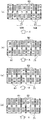
【解決手段】冷媒の流れ方向を転換させる冷媒側ターン部61eが形成された冷媒用チューブ61と走行用電動モータMGの冷却水の流れ方向を転換させる冷却媒体側ターン部71eが形成された冷却媒体用チューブ71とを、冷媒側ヘッダタンク62と冷却媒体ヘッダタンク72との間に互いに交互に積層配置する。この際、隣り合う冷媒用チューブ61と冷却水用チューブ43aとの間に形成される外気通路にアウターフィンを配置するとともに、冷媒側ターン部61eを冷媒側ヘッダタンク62よりも冷却媒体ヘッダタンク72の近い位置に位置付け、冷却媒体側ターン部71eを冷却媒体ヘッダタンク72よりも冷媒側ヘッダタンク62に近い位置に位置付ける。
【選択図】図11
Description
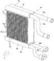
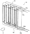
第1チューブ(61)および第2チューブ(71)は、第1タンク部(62)と第2タンク部(72)との間に配置され、複数の第1チューブ(61)のうち少なくとも1つは、複数の第2チューブ(71)の間に配置され、複数の第2チューブ(71)のうち少なくとも1つは、複数の第1チューブ(61)の間に配置され、第1チューブ(61)と第2チューブ(71)との間に形成される空間は、第3流体が流通する第3流体用通路(16a)を形成しており、第3流体用通路(16a)には、双方の熱交換部(60、70)における熱交換を促進するとともに、第1チューブ(61)を流通する第1流体と第2チューブ(71)を流通する第2流体との間の熱移動を可能とするアウターフィン(50)が配置され、
第1チューブ(61)には、第1流体の流れ方向を転換させる第1ターン部(61e)が設けられ、第2チューブ(71)には、第2流体の流れ方向を転換させる第2ターン部(71e)が設けられ、第1ターン部(61e)は、第1タンク部(62)よりも第2タンク部(72)に近い位置に位置付けられ、第2ターン部(71e)は、第2タンク部(72)よりも第1タンク部(62)に近い位置に位置付けられている熱交換器を特徴とする。
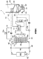
図1〜11により、本発明の第1実施形態を説明する。本実施形態では、本発明の熱交換器16を、車両用空調装置1において車室内送風空気の温度調節を行うヒートポンプサイクル10に適用している。図1〜4は、本実施形態の車両用空調装置1の全体構成図である。この車両用空調装置1は、内燃機関(エンジン)および走行用電動モータMGから車両走行用の駆動力を得る、いわゆるハイブリッド車両に適用されている。
暖房運転は、操作パネルの作動スイッチが投入(ON)された状態で、選択スイッチによって暖房運転モードが選択されると開始される。そして、暖房運転時に、着霜判定手段によって室外熱交換部60の着霜が生じていると判定された際には除霜運転が実行され、冷却水温度センサ52によって検出された冷却水温度Twが予め定めた基準温度(本実施形態では、60℃)度以上になった際には廃熱回収運転が実行される。
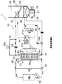
次に、除霜運転について説明する。ここで、本実施形態のヒートポンプサイクル10のように、室外熱交換部60にて冷媒と外気とを熱交換させて冷媒を蒸発させる冷凍サイクル装置では、室外熱交換部60における冷媒蒸発温度が着霜温度(具体的には、0℃)以下になってしまうと室外熱交換部60に着霜が生じるおそれがある。
次に、廃熱回収運転について説明する。ここで、走行用電動モータMGのオーバーヒートを抑制するためには、冷却水の温度は所定の上限温度以下に維持されるとともに、走行用電動モータMGの内部に封入された潤滑用オイルの粘度増加によるフリクションロスを低減するためには、冷却水の温度は所定の下限温度以上に維持されることが望ましい。
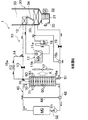
冷房運転は、操作パネルの作動スイッチが投入(ON)された状態で、選択スイッチによって冷房運転モードが選択されると開始される。この冷房運転時には、空調制御装置が、開閉弁15aを開くとともに、三方弁15bを室外熱交換部60の出口側と冷房用固定絞り19の入口側とを接続する冷媒流路に切り替える。これにより、ヒートポンプサイクル10は、図4の実線矢印に示すように冷媒が流れる冷媒流路に切り替えられる。
本実施形態では、第1実施形態に対して、熱交換器16の構成を変更した例を説明する。本実施形態の熱交換器16の詳細構成については、図12〜図14を用いて説明する。
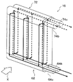
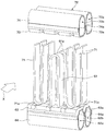
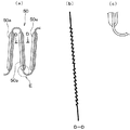
第2実施形態では、冷媒用チューブ61および冷却媒体用チューブ71として、その偏平面同士を互いに対向するように折り曲げた偏平チューブを採用した例を説明したが、本実施形態では、図15に示すように、各ターン部61e、71eの上流側の偏平面と下流側の偏平面が外気の流れ方向Xに沿って同一平面上に2列に並べて配置されるように折り曲げられている。
本実施形態では、図16の全体構成図に示すように、第1実施形態に対して、ヒートポンプサイクル10の構成を変更した例を説明する。なお、図16は、本実施形態における廃熱回収運転時の冷媒流路等を示す全体構成図であり、ヒートポンプサイクル10における冷媒の流れを実線で示し、冷却水循環回路40における冷却水の流れを破線矢印で示している。
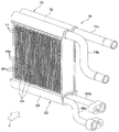
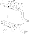
一方、室外熱交換部60については、内部を流通する冷媒と送風ファン17から送風された外気とを熱交換させる単一の熱交換器として構成されている。その他の構成は、第1実施形態と同様である。また、本実施形態では、除霜運転は実行されないものの、その他の作動は、第1実施形態と同様である。
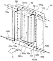
本実施形態では、第1実施形態に対して、熱交換器16の構成を変更した例を説明する。本実施形態の熱交換器16の詳細構成については、図17、図18を用いて説明する。
本発明は上述の実施形態に限定されることなく、本発明の趣旨を逸脱しない範囲内で、以下のように種々変形可能である。
16a 外気通路
50 アウターフィン
60 室外熱交換部
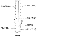
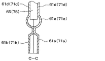
61 冷媒用チューブ
61a、61b 板状部材
61e 冷媒側ターン部
62 冷媒側ヘッダタンク部
65 インナーフィン
70 ラジエータ部
71 冷却媒体用チューブ
71a、71b 板状部材
71e 冷却媒体側ターン部
72 冷却媒体側ヘッダタンク部
75 インナーフィン
Claims (15)
- 第1流体が流通する複数本の第1チューブ(61)および前記複数本の第1チューブ(61)の積層方向に延びて前記第1チューブ(61)を流通する前記第1流体の集合あるいは分配を行う第1タンク部(62)を有し、前記第1流体と前記第1チューブ(61)の周囲を流れる第3流体とを熱交換させる第1熱交換部(60)と、
第2流体が流通する複数本の第2チューブ(71)および前記複数本の第2チューブ(71)の積層方向に延びて前記第2チューブ(71)を流通する前記第2流体の集合あるいは分配を行う第2タンク部(72)を有し、前記第2流体と前記第2チューブ(71)の周囲を流れる第3流体とを熱交換させる第2熱交換部(70)とを備え、
前記第1チューブ(61)および前記第2チューブ(71)は、前記第1タンク部(62)と前記第2タンク部(72)との間に配置され、
前記複数の第1チューブ(61)のうち少なくとも1つは、前記複数の第2チューブ(71)の間に配置され、
前記複数の第2チューブ(71)のうち少なくとも1つは、前記複数の第1チューブ(61)の間に配置され、
前記第1チューブ(61)と前記第2チューブ(71)との間に形成される空間は、前記第3流体が流通する第3流体用通路(16a)を形成しており、
前記第3流体用通路(16a)には、双方の熱交換部(60、70)における熱交換を促進するとともに、前記第1チューブ(61)を流通する前記第1流体と前記第2チューブ(71)を流通する前記第2流体との間の熱移動を可能とするアウターフィン(50)が配置され、
前記第1チューブ(61)には、前記第1流体の流れ方向を転換させる第1ターン部(61e)が設けられ、
前記第2チューブ(71)には、前記第2流体の流れ方向を転換させる第2ターン部(71e)が設けられ、
前記第1ターン部(61e)は、前記第1タンク部(62)よりも前記第2タンク部(72)に近い位置に位置付けられ、
前記第2ターン部(71e)は、前記第2タンク部(72)よりも前記第1タンク部(62)に近い位置に位置付けられていることを特徴とする熱交換器。 - 前記第1熱交換部(60)に導入される前記第1流体の温度は、前記第2熱交換部(70)に導入される前記第2流体の温度と異なっており、
前記アウターフィン(50)は、前記第1、第2チューブ(61、71)と、これに隣り合って配置される前記第1、第2チューブ(61、71)の間に形成される空間に配置されていることを特徴とする請求項1に記載の熱交換器。 - 前記第1チューブ(61)および前記第2チューブ(71)は、いずれも前記第1タンク部(62)および前記第2タンク部(72)の双方に固定されていることを特徴とする請求項1または2に記載の熱交換器。
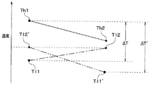
- 前記第1熱交換部(60)に導入される前記第1流体および前記第2熱交換部(70)に導入される前記第2流体のうち、温度が高い方の流体を高温側流体とし、
前記第1チューブ(61)および前記第2チューブ(71)のうち、前記高温側流体が流通する高温側チューブの前記第1、第2ターン部(61e、71e)よりも上流側を高温側チューブ上流部とし、
前記第1チューブ(61)および前記第2チューブ(71)のうち、前記高温側流体が流通する高温側チューブの前記第1、第2ターン部(61e、71e)よりも下流側を高温側チューブ下流部としたときに、
前記第3流体の温度は、前記高温側流体の温度よりも低く、
前記複数の高温側チューブのうち、少なくとも一部の前記高温側チューブ上流部は、前記高温側チューブ下流部に対して、前記第3流体の流れ方向上流側に配置されていることを特徴とする請求項1ないし3のいずれか1つに記載の熱交換器。 - 前記第1熱交換部(60)に導入される前記第1流体および前記第2熱交換部(70)に導入される前記第2流体のうち、温度が低い方の流体を低温側流体とし、
前記第1チューブ(61)および前記第2チューブ(71)のうち、前記低温側流体が流通する低温側チューブの前記第1、第2ターン部(61e、71e)よりも上流側を低温側チューブ上流部とし、
前記第1チューブ(61)および前記第2チューブ(71)のうち、前記低温側流体が流通する低温側チューブの前記第1、第2ターン部(61e、71e)よりも下流側を低温側チューブ下流部としたときに、
前記第3流体の温度は、前記低温側流体の温度よりも低く、
前記複数の低温側チューブのうち、少なくとも一部の前記低温側チューブ上流部は、前記低温側チューブ下流部に対して、前記第3流体の流れ方向上流側に配置されていることを特徴とする請求項4に記載の熱交換器。 - 前記第3流体の温度は、前記第1熱交換部(60)に導入される前記第1流体および前記第2熱交換部(70)に導入される前記第2流体のうち、温度が高い方の流体の温度よりも低く、かつ、温度が低い方の流体の温度よりも高くなっていることを特徴とする請求項1ないし4のいずれか1つに記載の熱交換器。
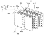
- 前記第1チューブ(61)の前記第1ターン部(61e)よりも上流側を第1チューブ上流部(611)とし、
前記第1チューブ(61)の前記第1ターン部(61e)よりも下流側を第1チューブ下流部(612)とし、
さらに、前記第2チューブ(71)の前記第2ターン部(71e)よりも上流側を第2チューブ上流部(711)とし、
前記第2チューブ(71)の前記第2ターン部(71e)よりも下流側を第2チューブ下流部(712)としたときに、
前記第1チューブ上流部(611)および前記第2チューブ上流部(711)は、前記第1、第2チューブ(61、71)の積層方向に並ぶように配置され、
前記第1チューブ下流部(612)および前記第2チューブ下流部(712)は、前記第1、第2チューブ(61、71)の積層方向に並ぶように配置されていることを特徴とする請求項1ないし3のいずれか1つに記載の熱交換器。 - 前記第1チューブ上流部(611)および前記第2チューブ上流部(711)は、前記第1チューブ下流部(612)および前記第2チューブ下流部(712)に対して、前記第3流体の流れ方向上流側に配置されていることを特徴とする請求項7に記載の熱交換器。
- 前記複数の第1チューブ(61)は、前記第1熱交換部(60)に導入される前記第1流体が流通する上流側第1チューブ群(60a)、および前記上流側第1チューブ群(60a)から流出して前記第1熱交換部(60)から導出される前記第1流体が流通する下流側第1チューブ群(60b)を有し、
前記複数の第2チューブ(71)は、前記第2熱交換部(70)に導入される前記第2流体が流通する上流側第2チューブ群(70a)、および前記上流側第2チューブ群(70a)から流出して前記第2熱交換部(70)から導出される前記第2流体が流通する下流側第2チューブ群(70b)を有し、
前記上流側第1チューブ群(60a)および前記上流側第2チューブ群(70a)における前記第1チューブ上流部(611)および前記第2チューブ上流部(711)は、前記第1チューブ下流部(612)および前記第2チューブ下流部(712)に対して、前記第3流体の流れ方向上流側に配置されていることを特徴とする請求項7に記載の熱交換器。 - 前記下流側第1チューブ群(60b)および前記下流側第2チューブ群(70b)における前記第1チューブ上流部(611)および前記第2チューブ上流部(711)は、前記第1チューブ下流部(612)および前記第2チューブ下流部(712)に対して、前記第3流体の流れ方向下流側に配置されていることを特徴とする請求項9に記載の熱交換器。
- 前記アウターフィン(50)は、前記第1、第2チューブ(61、71)に接合されると共に、局部的に剛性を弱めるための複数のスリット(50a)が形成されていることを特徴とする請求項1ないし10のいずれか1つに記載の熱交換器。
- 前記第1ターン部(61e)および前記第2ターン部(71e)の少なくとも一方の中間部の冷媒通路面積は、その流体流入部および流体流出部の流体通路面積よりも大きく形成されていることを特徴とする請求項1ないし11のいずれか1つに記載の熱交換器。
- 前記第1チューブ(61)および前記第2チューブ(71)の少なくとも一方の内部には、内部を流通する第1流体あるいは第2流体と前記第3流体との熱交換を促進するインナーフィン(65、75)が配置されており、
前記インナーフィン(65、75)の端部は、前記第1ターン部(61e)あるいは前記第2ターン部(71e)の内部空間に突出していることを特徴とする請求項1ないし12のいずれか1つに記載の熱交換器。 - 前記第1チューブ(61)および前記第2チューブ(71)は、一対の板状部材(61a、61b、71a、71b)を貼り合わせて形成されたプレートチューブで構成されていることを特徴とする請求項1ないし13のいずれか1つに記載の熱交換器。
- 前記第1チューブ(61)および前記第2チューブ(71)は、長手方向垂直断面が偏平形状に形成された偏平チューブを折り曲げることによって形成されたものであることを特徴とする請求項1ないし13のいずれか1つに記載の熱交換器。
Priority Applications (5)
| Application Number | Priority Date | Filing Date | Title |
|---|---|---|---|
| JP2011233083A JP5413433B2 (ja) | 2010-11-09 | 2011-10-24 | 熱交換器 |
| PCT/JP2011/006190 WO2012063454A1 (ja) | 2010-11-09 | 2011-11-07 | 熱交換器 |
| US13/884,086 US20130240185A1 (en) | 2010-11-09 | 2011-11-07 | Heat exchanger |
| DE112011103727T DE112011103727T5 (de) | 2010-11-09 | 2011-11-07 | Wärmetauscher |
| CN201180054056.XA CN103201580B (zh) | 2010-11-09 | 2011-11-07 | 热交换器 |
Applications Claiming Priority (3)
| Application Number | Priority Date | Filing Date | Title |
|---|---|---|---|
| JP2010251119 | 2010-11-09 | ||
| JP2010251119 | 2010-11-09 | ||
| JP2011233083A JP5413433B2 (ja) | 2010-11-09 | 2011-10-24 | 熱交換器 |
Publications (2)
| Publication Number | Publication Date |
|---|---|
| JP2012117802A true JP2012117802A (ja) | 2012-06-21 |
| JP5413433B2 JP5413433B2 (ja) | 2014-02-12 |
Family
ID=46050623
Family Applications (1)
| Application Number | Title | Priority Date | Filing Date |
|---|---|---|---|
| JP2011233083A Expired - Fee Related JP5413433B2 (ja) | 2010-11-09 | 2011-10-24 | 熱交換器 |
Country Status (5)
| Country | Link |
|---|---|
| US (1) | US20130240185A1 (ja) |
| JP (1) | JP5413433B2 (ja) |
| CN (1) | CN103201580B (ja) |
| DE (1) | DE112011103727T5 (ja) |
| WO (1) | WO2012063454A1 (ja) |
Cited By (4)
| Publication number | Priority date | Publication date | Assignee | Title |
|---|---|---|---|---|
| JP2021146944A (ja) * | 2020-03-19 | 2021-09-27 | トヨタ自動車株式会社 | 熱管理装置 |
| KR20230061744A (ko) * | 2021-10-29 | 2023-05-09 | 한국원자력연구원 | 인쇄기판형 열교환기 |
| WO2025048356A1 (ko) * | 2023-08-28 | 2025-03-06 | 주식회사 케이엠더블유 | 응축판부 조립체 및 이를 포함하는 방열 장치 |
| KR20250032954A (ko) * | 2023-08-28 | 2025-03-07 | 주식회사 케이엠더블유 | 응축판부 조립체 및 이를 포함하는 방열 장치 |
Families Citing this family (16)
| Publication number | Priority date | Publication date | Assignee | Title |
|---|---|---|---|---|
| US10247482B2 (en) * | 2013-12-13 | 2019-04-02 | Hangzhou Sanhua Research Institute Co., Ltd. | Bent heat exchanger and method for bending the heat exchanger |
| JP2015157507A (ja) * | 2014-02-21 | 2015-09-03 | 株式会社ケーヒン・サーマル・テクノロジー | 車両用空調装置 |
| DE102014203895B4 (de) * | 2014-03-04 | 2018-08-16 | Konvekta Ag | Kälteanlage |
| CN104654433B (zh) * | 2014-12-31 | 2018-05-01 | 宁波先锋电器制造有限公司 | 带有曲折散热部的散热片及使用该散热片的电热油汀 |
| US20170211899A1 (en) * | 2016-01-27 | 2017-07-27 | GM Global Technology Operations LLC | Heat exchangers containing carbon nanotubes and methods for the manufacture thereof |
| CN105928394A (zh) * | 2016-05-11 | 2016-09-07 | 南京工业大学 | 一种层叠式翅片管换热器 |
| JP6237942B1 (ja) * | 2017-01-30 | 2017-11-29 | 富士通株式会社 | 液浸冷却装置 |
| JP6870570B2 (ja) * | 2017-10-26 | 2021-05-12 | 株式会社デンソー | 車両用熱管理システム |
| WO2019183312A1 (en) * | 2018-03-23 | 2019-09-26 | Modine Manufacturing Company | High pressure capable liquid to refrigerant heat exchanger |
| KR102600972B1 (ko) | 2018-12-28 | 2023-11-13 | 삼성전자주식회사 | 열교환기 |
| JP7099392B2 (ja) * | 2019-04-03 | 2022-07-12 | トヨタ自動車株式会社 | 車載温調装置 |
| JP7329373B2 (ja) * | 2019-07-01 | 2023-08-18 | 三菱重工サーマルシステムズ株式会社 | 空気調和ユニット、熱交換器、および空気調和機 |
| DE102019008914A1 (de) * | 2019-12-20 | 2021-06-24 | Stiebel Eltron Gmbh & Co. Kg | Wärmepumpe mit optimiertem Kältemittelkreislauf |
| CN110895112A (zh) * | 2019-12-23 | 2020-03-20 | 浙江银轮机械股份有限公司 | 发动机尾气蒸发过热器 |
| EP4155626B1 (en) * | 2020-05-22 | 2025-09-03 | Mitsubishi Electric Corporation | Heat exchanger, outdoor unit equipped with heat exchanger, and air conditioner equipped with outdoor unit |
| CN112964092A (zh) * | 2021-02-17 | 2021-06-15 | 姜黎平 | 一种双向鼓包型套管式换热器 |
Citations (8)
| Publication number | Priority date | Publication date | Assignee | Title |
|---|---|---|---|---|
| JPS58129297U (ja) * | 1982-02-25 | 1983-09-01 | 三井造船株式会社 | 舶用油加熱器 |
| JPH0194775U (ja) * | 1987-12-14 | 1989-06-22 | ||
| JPH0630680U (ja) * | 1992-09-09 | 1994-04-22 | カルソニック株式会社 | 積層型エバポレータの素子 |
| JPH08210788A (ja) * | 1995-02-06 | 1996-08-20 | Showa Alum Corp | 熱交換器 |
| JPH11153395A (ja) * | 1997-09-19 | 1999-06-08 | Showa Alum Corp | 自動車用一体型熱交換器 |
| JPH11157326A (ja) * | 1997-11-26 | 1999-06-15 | Calsonic Corp | 熱交換器 |
| JP2002107004A (ja) * | 2000-09-27 | 2002-04-10 | Calsonic Kansei Corp | 積層型エバポレータ |
| JP2010117091A (ja) * | 2008-11-13 | 2010-05-27 | Denso Corp | 熱交換器 |
Family Cites Families (8)
| Publication number | Priority date | Publication date | Assignee | Title |
|---|---|---|---|---|
| KR0143540B1 (ko) * | 1992-08-27 | 1998-08-01 | 코오노 미찌아끼 | 편평튜브와 물결형휜을 교호로 적층해서 이루어진 적층형 열교환기 및 그 제조방법 |
| FR2728666A1 (fr) * | 1994-12-26 | 1996-06-28 | Valeo Thermique Habitacle | Echangeur de chaleur a trois fluides d'encombrement reduit |
| DE19825561A1 (de) * | 1998-06-08 | 1999-12-09 | Valeo Klimatech Gmbh & Co Kg | Wärmetauscher mit verrippten Flachrohren, insbesondere Heizungswärmetauscher, Motorkühler, Verflüssiger oder Verdampfer, für Kraftfahrzeuge |
| AUPQ619900A0 (en) * | 2000-03-14 | 2000-04-06 | Urch, John Francis | Total-heat moulded frame heat exchanger |
| AU2002363887A1 (en) * | 2001-12-21 | 2003-07-09 | Behr Gmbh And Co. | Heat exchanger, particularly for a motor vehicle |
| JP4321242B2 (ja) * | 2003-12-02 | 2009-08-26 | 株式会社デンソー | 車両用空調装置 |
| JP2010251119A (ja) | 2009-04-15 | 2010-11-04 | Swcc Showa Cable Systems Co Ltd | バッテリーケーブル用コネクタ構造 |
| JP2011233083A (ja) | 2010-04-30 | 2011-11-17 | Mitsubishi Electric Corp | 目標検出装置及びコンピュータプログラム及び目標検出方法 |
-
2011
- 2011-10-24 JP JP2011233083A patent/JP5413433B2/ja not_active Expired - Fee Related
- 2011-11-07 US US13/884,086 patent/US20130240185A1/en not_active Abandoned
- 2011-11-07 WO PCT/JP2011/006190 patent/WO2012063454A1/ja not_active Ceased
- 2011-11-07 CN CN201180054056.XA patent/CN103201580B/zh not_active Expired - Fee Related
- 2011-11-07 DE DE112011103727T patent/DE112011103727T5/de not_active Withdrawn
Patent Citations (8)
| Publication number | Priority date | Publication date | Assignee | Title |
|---|---|---|---|---|
| JPS58129297U (ja) * | 1982-02-25 | 1983-09-01 | 三井造船株式会社 | 舶用油加熱器 |
| JPH0194775U (ja) * | 1987-12-14 | 1989-06-22 | ||
| JPH0630680U (ja) * | 1992-09-09 | 1994-04-22 | カルソニック株式会社 | 積層型エバポレータの素子 |
| JPH08210788A (ja) * | 1995-02-06 | 1996-08-20 | Showa Alum Corp | 熱交換器 |
| JPH11153395A (ja) * | 1997-09-19 | 1999-06-08 | Showa Alum Corp | 自動車用一体型熱交換器 |
| JPH11157326A (ja) * | 1997-11-26 | 1999-06-15 | Calsonic Corp | 熱交換器 |
| JP2002107004A (ja) * | 2000-09-27 | 2002-04-10 | Calsonic Kansei Corp | 積層型エバポレータ |
| JP2010117091A (ja) * | 2008-11-13 | 2010-05-27 | Denso Corp | 熱交換器 |
Cited By (9)
| Publication number | Priority date | Publication date | Assignee | Title |
|---|---|---|---|---|
| JP2021146944A (ja) * | 2020-03-19 | 2021-09-27 | トヨタ自動車株式会社 | 熱管理装置 |
| CN113492661A (zh) * | 2020-03-19 | 2021-10-12 | 丰田自动车株式会社 | 热管理装置 |
| JP7328171B2 (ja) | 2020-03-19 | 2023-08-16 | トヨタ自動車株式会社 | 熱管理装置 |
| CN113492661B (zh) * | 2020-03-19 | 2024-02-06 | 丰田自动车株式会社 | 热管理装置 |
| KR20230061744A (ko) * | 2021-10-29 | 2023-05-09 | 한국원자력연구원 | 인쇄기판형 열교환기 |
| KR102582442B1 (ko) * | 2021-10-29 | 2023-09-25 | 한국원자력연구원 | 인쇄기판형 열교환기 |
| WO2025048356A1 (ko) * | 2023-08-28 | 2025-03-06 | 주식회사 케이엠더블유 | 응축판부 조립체 및 이를 포함하는 방열 장치 |
| KR20250032954A (ko) * | 2023-08-28 | 2025-03-07 | 주식회사 케이엠더블유 | 응축판부 조립체 및 이를 포함하는 방열 장치 |
| KR102904471B1 (ko) * | 2023-08-28 | 2025-12-29 | 주식회사 케이엠더블유 | 응축판부 조립체 및 이를 포함하는 방열 장치 |
Also Published As
| Publication number | Publication date |
|---|---|
| CN103201580A (zh) | 2013-07-10 |
| US20130240185A1 (en) | 2013-09-19 |
| DE112011103727T5 (de) | 2013-09-26 |
| WO2012063454A1 (ja) | 2012-05-18 |
| CN103201580B (zh) | 2015-06-24 |
| JP5413433B2 (ja) | 2014-02-12 |
Similar Documents
| Publication | Publication Date | Title |
|---|---|---|
| JP5413433B2 (ja) | 熱交換器 | |
| JP5853948B2 (ja) | 熱交換器 | |
| JP5920175B2 (ja) | 熱交換器 | |
| JP5772672B2 (ja) | 熱交換器 | |
| JP5983335B2 (ja) | 熱交換器 | |
| JP5626194B2 (ja) | 熱交換システム | |
| JP5796563B2 (ja) | 熱交換器 | |
| JP5751028B2 (ja) | ヒートポンプサイクル | |
| JP5413313B2 (ja) | 熱交換器 | |
| US9625214B2 (en) | Heat exchanger | |
| JP5983387B2 (ja) | 熱交換器 |
Legal Events
| Date | Code | Title | Description |
|---|---|---|---|
| A621 | Written request for application examination |
Free format text: JAPANESE INTERMEDIATE CODE: A621 Effective date: 20130220 |
|
| TRDD | Decision of grant or rejection written | ||
| A01 | Written decision to grant a patent or to grant a registration (utility model) |
Free format text: JAPANESE INTERMEDIATE CODE: A01 Effective date: 20131015 |
|
| A61 | First payment of annual fees (during grant procedure) |
Free format text: JAPANESE INTERMEDIATE CODE: A61 Effective date: 20131028 |
|
| R151 | Written notification of patent or utility model registration |
Ref document number: 5413433 Country of ref document: JP Free format text: JAPANESE INTERMEDIATE CODE: R151 |
|
| R250 | Receipt of annual fees |
Free format text: JAPANESE INTERMEDIATE CODE: R250 |
|
| R250 | Receipt of annual fees |
Free format text: JAPANESE INTERMEDIATE CODE: R250 |
|
| R250 | Receipt of annual fees |
Free format text: JAPANESE INTERMEDIATE CODE: R250 |
|
| R250 | Receipt of annual fees |
Free format text: JAPANESE INTERMEDIATE CODE: R250 |
|
| R250 | Receipt of annual fees |
Free format text: JAPANESE INTERMEDIATE CODE: R250 |
|
| R250 | Receipt of annual fees |
Free format text: JAPANESE INTERMEDIATE CODE: R250 |
|
| LAPS | Cancellation because of no payment of annual fees |