JP2012120761A - Injection needle protector, injection needle unit, and injector to which the injection needle unit is mounted - Google Patents
Injection needle protector, injection needle unit, and injector to which the injection needle unit is mounted Download PDFInfo
- Publication number
- JP2012120761A JP2012120761A JP2010275332A JP2010275332A JP2012120761A JP 2012120761 A JP2012120761 A JP 2012120761A JP 2010275332 A JP2010275332 A JP 2010275332A JP 2010275332 A JP2010275332 A JP 2010275332A JP 2012120761 A JP2012120761 A JP 2012120761A
- Authority
- JP
- Japan
- Prior art keywords
- cap
- needle
- syringe
- needle tube
- injection needle
- Prior art date
- Legal status (The legal status is an assumption and is not a legal conclusion. Google has not performed a legal analysis and makes no representation as to the accuracy of the status listed.)
- Pending
Links
Images





Classifications
-
- A—HUMAN NECESSITIES
- A61—MEDICAL OR VETERINARY SCIENCE; HYGIENE
- A61M—DEVICES FOR INTRODUCING MEDIA INTO, OR ONTO, THE BODY; DEVICES FOR TRANSDUCING BODY MEDIA OR FOR TAKING MEDIA FROM THE BODY; DEVICES FOR PRODUCING OR ENDING SLEEP OR STUPOR
- A61M5/00—Devices for bringing media into the body in a subcutaneous, intra-vascular or intramuscular way; Accessories therefor, e.g. filling or cleaning devices, arm-rests
- A61M5/178—Syringes
- A61M5/31—Details
- A61M5/32—Needles; Details of needles pertaining to their connection with syringe or hub; Accessories for bringing the needle into, or holding the needle on, the body; Devices for protection of needles
- A61M5/3202—Devices for protection of the needle before use, e.g. caps
-
- A—HUMAN NECESSITIES
- A61—MEDICAL OR VETERINARY SCIENCE; HYGIENE
- A61J—CONTAINERS SPECIALLY ADAPTED FOR MEDICAL OR PHARMACEUTICAL PURPOSES; DEVICES OR METHODS SPECIALLY ADAPTED FOR BRINGING PHARMACEUTICAL PRODUCTS INTO PARTICULAR PHYSICAL OR ADMINISTERING FORMS; DEVICES FOR ADMINISTERING FOOD OR MEDICINES ORALLY; BABY COMFORTERS; DEVICES FOR RECEIVING SPITTLE
- A61J1/00—Containers specially adapted for medical or pharmaceutical purposes
- A61J1/14—Details; Accessories therefor
- A61J1/20—Arrangements for transferring or mixing fluids, e.g. from vial to syringe
- A61J1/2096—Combination of a vial and a syringe for transferring or mixing their contents
-
- A—HUMAN NECESSITIES
- A61—MEDICAL OR VETERINARY SCIENCE; HYGIENE
- A61M—DEVICES FOR INTRODUCING MEDIA INTO, OR ONTO, THE BODY; DEVICES FOR TRANSDUCING BODY MEDIA OR FOR TAKING MEDIA FROM THE BODY; DEVICES FOR PRODUCING OR ENDING SLEEP OR STUPOR
- A61M5/00—Devices for bringing media into the body in a subcutaneous, intra-vascular or intramuscular way; Accessories therefor, e.g. filling or cleaning devices, arm-rests
- A61M5/178—Syringes
- A61M5/1782—Devices aiding filling of syringes in situ
-
- A—HUMAN NECESSITIES
- A61—MEDICAL OR VETERINARY SCIENCE; HYGIENE
- A61J—CONTAINERS SPECIALLY ADAPTED FOR MEDICAL OR PHARMACEUTICAL PURPOSES; DEVICES OR METHODS SPECIALLY ADAPTED FOR BRINGING PHARMACEUTICAL PRODUCTS INTO PARTICULAR PHYSICAL OR ADMINISTERING FORMS; DEVICES FOR ADMINISTERING FOOD OR MEDICINES ORALLY; BABY COMFORTERS; DEVICES FOR RECEIVING SPITTLE
- A61J1/00—Containers specially adapted for medical or pharmaceutical purposes
- A61J1/14—Details; Accessories therefor
- A61J1/20—Arrangements for transferring or mixing fluids, e.g. from vial to syringe
- A61J1/2003—Accessories used in combination with means for transfer or mixing of fluids, e.g. for activating fluid flow, separating fluids, filtering fluid or venting
- A61J1/2006—Piercing means
- A61J1/201—Piercing means having one piercing end
Landscapes
- Health & Medical Sciences (AREA)
- Life Sciences & Earth Sciences (AREA)
- Veterinary Medicine (AREA)
- Public Health (AREA)
- General Health & Medical Sciences (AREA)
- Animal Behavior & Ethology (AREA)
- Anesthesiology (AREA)
- Hematology (AREA)
- Heart & Thoracic Surgery (AREA)
- Biomedical Technology (AREA)
- Engineering & Computer Science (AREA)
- Vascular Medicine (AREA)
- Pharmacology & Pharmacy (AREA)
- Infusion, Injection, And Reservoir Apparatuses (AREA)
Abstract
【課題】薬剤混合装置に複雑な構成を施すことなく、注射器の針先を薬剤容器に正確に挿入させるための注射針保護具、注射針ユニットおよびこれを装着した注射器を提供することを目的とする。
【解決手段】針基13に接続された針管9に被せられて前記針管9を保護する注射針保護具1であって、針基13側の針管9を保護するとともに、注射器保持機によって保持される第一キャップ5と、第一キャップ5によって保護されない残りの針管9を保護する第二キャップ7と、を備え、第一キャップ5には、針管9を外周から支持する支持部11が備えられている。
【選択図】図4An object of the present invention is to provide an injection needle protector, an injection needle unit, and a syringe equipped with the same for allowing a needle tip of a syringe to be accurately inserted into a drug container without applying a complicated configuration to the drug mixing device. To do.
An injection needle protector that covers a needle tube connected to a needle base and protects the needle tube. The needle protection device protects the needle tube on the side of the needle base and is held by a syringe holder. A first cap 5 and a second cap 7 that protects the remaining needle tube 9 that is not protected by the first cap 5. The first cap 5 is provided with a support portion 11 that supports the needle tube 9 from the outer periphery. ing.
[Selection] Figure 4
Description
本発明は、注射針を保護する注射針保護具、注射針ユニットおよびこれを装着した注射器に関するものである。より詳細には、注射器保持機に保持されるための注射針保護具、注射針ユニットおよびこれを装着した注射器に関するものである。 The present invention relates to an injection needle protector for protecting an injection needle, an injection needle unit, and a syringe equipped with the same. More particularly, the present invention relates to a needle protection device to be held by a syringe holder, a needle unit, and a syringe equipped with the same.
看護婦や薬剤師が薬剤の入ったバイアルなどの薬剤容器に注射器の針管を穿刺させる作業は、負担が大きく正確性が求められる。特に、異なる薬剤を混合調製する作業は穿刺の回数が多いのでより負担の低減と正確性が求められる。また、放射性医薬品や抗がん剤などの危険医薬品を扱う場合は無菌的に行う必要がある。そのため、装置による穿刺作業の自動化が求められている。 An operation in which a nurse or a pharmacist punctures a needle tube of a syringe into a drug container such as a vial containing a drug is heavy and requires accuracy. In particular, the work of mixing and preparing different drugs requires a lot of punctures, so that a reduction in burden and accuracy are required. In addition, when handling dangerous drugs such as radiopharmaceuticals and anticancer drugs, it must be done aseptically. Therefore, there is a demand for automation of the puncture work by the device.
例えば薬剤混合装置のように穿刺作業を行う装置に用いられる注射器は、針管とこの一端と接続する針基を備える注射針ユニット、針基と接続される注射筒(シリンジ)および押子を有している。そして、誤った穿刺を防ぐために、略円筒形状の注射針保護具が針基に嵌め込まれている。このような注射器は、針保護具を装着したまま薬剤混合装置に導入され、薬剤混合装置などの装置の一部を構成する注射器保持機に注射器の注射筒が保持されることで注射器保持機に固定される(特許文献1)。 For example, a syringe used in a device that performs a puncturing operation, such as a drug mixing device, has a needle unit having a needle tube and a needle base connected to one end thereof, a syringe barrel (syringe) connected to the needle base, and a pusher. ing. In order to prevent erroneous puncture, a substantially cylindrical injection needle protector is fitted into the needle base. Such a syringe is introduced into the drug mixing device with the needle protector attached, and the syringe barrel of the syringe is held in a syringe holding machine that constitutes a part of the device such as the drug mixing device. It is fixed (Patent Document 1).
しかしながら従来技術では、薬剤が入った容器の口に注射器の針先を正確に穿刺させるための新たな構成が必要となり装置が複雑となってしまう。 However, the conventional technology requires a new configuration for accurately puncturing the needle tip of the syringe into the mouth of the container containing the medicine, which complicates the apparatus.
すなわち、正確な穿刺を行うには注射器保持機に注射器を固定させる必要があるが、注射器保持機は、衛生上の観点から針管を直接保持することができない。そのため、注射器の注射筒を保持することで注射器を注射器保持機に固定させている。 That is, in order to perform accurate puncture, it is necessary to fix the syringe to the syringe holder, but the syringe holder cannot directly hold the needle tube from the viewpoint of hygiene. Therefore, the syringe is fixed to the syringe holder by holding the syringe barrel of the syringe.
しかし、注射筒を固定しても注射筒の筒先と針基、および針基と針管との接合の度合い、注射筒、針基および針管などの製造誤差によって針先の位置には針管の径方向にバラツキが生じる。 However, even if the syringe barrel is fixed, the needle tube is positioned in the radial direction of the needle tube depending on the degree of joining between the tube tip and the needle base, the needle base and the needle tube, and the manufacturing error of the syringe tube, needle base, and needle tube. Variation occurs.
その結果、薬剤が入った容器の口に注射器の針先を正確に穿刺させるには、針先の位置や針管の傾きを把握するためのカメラや制御などが必要となり、注射器保持機やこれを含む装置の構成が複雑となってしまうのである。 As a result, in order to accurately puncture the needle tip of the syringe into the mouth of the container containing the medicine, a camera and control for grasping the position of the needle tip and the inclination of the needle tube are necessary. The configuration of the device including it becomes complicated.
そこで本発明は、注射器保持機やこれを含む装置に複雑な構成を施すことなく、注射器の針先を薬剤容器に正確に挿入させるための注射針保護具、注射針ユニットおよびこれを装着した注射器を提供することを目的とするものである。 Therefore, the present invention provides a syringe protection device, a syringe needle unit, and a syringe equipped with the syringe needle for accurately inserting the needle tip of the syringe into a medicine container without giving a complicated configuration to the syringe holder and the apparatus including the syringe holder. Is intended to provide.
そして、その目的を達成するために本発明は、針基に接続された針管に被せられて前記針管を保護する注射針保護具であって、前記針基側の前記針管を保護するとともに、注射器保持機によって保持される第一キャップと、前記第一キャップによって保護されない残りの前記針管を保護する第二キャップと、を備え、前記第一キャップには、前記針管を外周から支持する支持部が備えられていることを特徴としている。 In order to achieve the object, the present invention provides an injection needle protector that covers a needle tube connected to a needle base and protects the needle tube, and protects the needle tube on the needle base side, and a syringe. A first cap held by a holder, and a second cap for protecting the remaining needle tube that is not protected by the first cap, wherein the first cap has a support portion that supports the needle tube from the outer periphery. It is characterized by being provided.
これによれば、注射器保持機やこれを含む装置に複雑な構成を施すことなく、注射器の針先を薬剤容器に正確に穿刺させることができる。すなわち、注射針保護具を適用した注射器は、第二キャップを外しても第一キャップが保持されることによって注射器保持機に固定させられるので、注射器保持機やこれを含む装置に複雑な構成を施すことなく、注射器の針先を薬剤容器に正確に穿刺させることができる。 According to this, the needle tip of the syringe can be accurately punctured into the medicine container without applying a complicated configuration to the syringe holder and the apparatus including the syringe holder. That is, since the syringe to which the needle protection device is applied is fixed to the syringe holder by holding the first cap even if the second cap is removed, the syringe holder and the apparatus including the syringe have a complicated configuration. Without application, the needle tip of the syringe can be accurately punctured into the drug container.
また、前記の注射針保護具の第一キャップの支持部は、前記第一キャップの先端に備えられていることが好ましい。 Moreover, it is preferable that the support part of the first cap of the injection needle protector is provided at the tip of the first cap.
これによって、第一キャップの支持部が針先側の針管を支持できるため、注射針保護具を装着した注射器の針先の位置には針管の径方向のバラツキが少なくなり、より正確に薬剤容器に穿刺させることができる。 As a result, since the support portion of the first cap can support the needle tube on the needle tip side, there is less variation in the radial direction of the needle tube at the position of the needle tip of the syringe equipped with the injection needle protector, and the drug container is more accurately Can be punctured.
また、前記第一キャップに鍔部が備えられていることが好ましい。 Moreover, it is preferable that the said 1st cap is equipped with the collar part.
これによれば、注射針保護具を適用した注射器の針管に薬剤が付着しても、鍔部によって薬剤が第一キャップの側面に付着するのを防止することができ、衛生的となる。その結果、第一キャップを保持する注射器保持機に薬剤が付着しにくくなり、付着した薬剤を洗い流す手段が必要とならない。 According to this, even if the drug adheres to the needle tube of the syringe to which the injection needle protector is applied, it is possible to prevent the drug from adhering to the side surface of the first cap by the buttocks, which is hygienic. As a result, it becomes difficult for the drug to adhere to the syringe holder that holds the first cap, and no means for washing away the adhered drug is required.
また、前記鍔部は、前記支持部よりも前記針管の針先側に設けられていることが好ましい。 Moreover, it is preferable that the said collar part is provided in the needle point side of the said needle tube rather than the said support part.
これによって、注射針保護具を適用した注射器の針管に付着する薬剤の広がりを効果的に抑えることができる。また、第一キャップが注射器保持機によって保持される領域を多く確保することができる。 Accordingly, it is possible to effectively suppress the spread of the medicine attached to the needle tube of the syringe to which the syringe needle protector is applied. Moreover, many areas where the first cap is held by the syringe holder can be secured.
また、前記注射器保持機によって保持される前記第一キャップの部位は、前記支持部であることが好ましい。 Moreover, it is preferable that the site | part of the said 1st cap hold | maintained by the said syringe holder is the said support part.
第一キャップのうち、注射器保持機に保持される部分が針管と接して支持する支持部であることで、注射器保持機よる保持力が支持部を通してより針管に伝わりやすくなる。 Since the portion of the first cap that is held by the syringe holder is a support portion that is in contact with and supports the needle tube, the holding force by the syringe holder is more easily transmitted to the needle tube through the support portion.
さらに、前記支持部の内壁は、前記針管の外周と密着していることが好ましい。 Furthermore, it is preferable that the inner wall of the support portion is in close contact with the outer periphery of the needle tube.
これによって、注射器保持機による保持力が支持部を通してさらに針管に伝わりやすくなる。 Thereby, the holding force by the syringe holder can be further easily transmitted to the needle tube through the support portion.
本発明によれば、注射器保持機やこれを含む装置に複雑な構成を施すことなく、注射器の針先を薬剤容器に正確に穿刺させることができる。 ADVANTAGE OF THE INVENTION According to this invention, the needle | hook tip of a syringe can be correctly punctured to a chemical | medical agent container, without giving a complicated structure to a syringe holder and an apparatus including the same.
(実施の形態1)
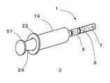
以下に、本発明の注射針保護具1を図面とともに詳細に説明する。図1は、本発明の注射保護具1を装着した注射器3の斜視図である。注射器3は、注射器保持機21用のもので、注射器保持機21に固定されることで穿刺を自動的に行う。
(Embodiment 1)
Below, the
注射保護具1は、第一キャップ5と第二キャップ7から構成されており、第二キャップ7を外しても注射器保持機21が第一キャップ5を保持し、針管9を注射器保持機21に対して正確な位置に固定することができる。その結果、注射器保持機21やこれを含む図示しない薬剤混合装置に複雑な構成を施す必要がなくなる点が本発明の要点である。
The
図2は、本発明の注射針保護具1の正面図である。第一キャップ5は、円筒部59と、円筒部59より狭径の円筒の外形を有する支持部11から構成され、円筒部59と支持部11が同軸上に配置されている。
FIG. 2 is a front view of the
第一キャップ5の内部には、円筒形状の空間と、針管9の外周とほぼ同じ径であって、針管9を受け入れて外周からこれを支持する狭径の円筒形状をした空間と、これらの空間を接続する先細りテーパー形状の空間が形成されている。また、これらの空間の長手方向の中心軸は互いに一致している。
Inside the
有底円筒形状の第二キャップ7は、この開口端が第一キャップ5の支持部11の全体に被さるように第一キャップ5と着脱可能に嵌め込まれ、円筒部59の支持部11側の縁部によって位置決めされる。
The bottomed cylindrical
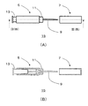
図3は、このような注射針保護具1を針管9および針基13に適用した注射針ユニット15を示している。ここで、注射針ユニット15は、針管9と、針管9と接続される針基13と、第一キャップ5と、第二キャップ7とを含んでいる。なお、図3(B)は、図3(A)のIII(B)−III(B)断面を示すが、針管9および針基13は断面ではなく正面を示している。
FIG. 3 shows an
図3に示されるように、針管9の一端部と接続された針基13は、第一キャップ5の支持部11とは反対側の開口端に締め付けられて固定される。この状態で、針基13の先端から針先までの針管9のうち、長手方向に対しほぼ中央部分は、支持部11によって外周が支持される構成となっている。そして、支持部11と針管9とは、密着する構成となっている。すなわち、支持部11の内壁55は、針管9の外周と密着している。
As shown in FIG. 3, the
したがって、第一キャップ5は、針基13から延出する針管9から、支持部11によって直接支持された針管9までの針基13側の一部を外部から保護する機能を有するとともに、第一キャップ5を固定すればこれと同時に針管9も固定する機能を有している。ここで、針管9および針基13は、金型で成型された第一キャップ5の開口する底面側から挿入されて固定第一キャップ5に固定されてもよいが、針管9および針基13を、長手方向に2つ(またはそれ以上)に分割された第一キャップ5の断片によって挟み、断片を圧着することで第一キャップ5の円筒形状を構成しながら固定されてもよい。
Accordingly, the
第二キャップ7は、第一キャップ5によって保護されない残りの針管9の部分、すなわち、支持部11から針先までの針管9を保護する構成となっている。ここで、第二キャップ7によって覆われる針管9の長さは、バイアルなどの薬剤容器17を用いて混合調製を行える長さに調整されている。
The
図4は、以上のような注射針ユニット15を注射器3の注射筒19の先端部に接続した様子を示している。この接続は、針基13の第一キャップ5によって覆われていない部分を注射筒19の先端の開口に挿入することでなされている。この固定はネジ構造などの周知の方法によって可能である。
FIG. 4 shows a state in which the
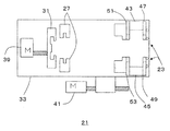
次に、注射針保護具1を装着した注射器3を固定するための注射器保持機21について説明を行う。注射器保持機21は、何らかの動作を注射器3にさせるために注射器3を保持するものであり、注射器3を保持するマニピュレータの一部構成であってもよい。図5に示されるように、注射器保持機21は、注射針保護具1の第一キャップ5を固定するキャップ固定部23と、注射筒19の端部に設けられたフランジ25を保持するためのフランジ保持部27と、注射器3の押子29を保持する押子保持部31とを主な構成としており、これらはベース33上に配置されている。また、注射器保持機21は、キャップ固定部23、押子保持部31およびベース33をそれぞれ可動させるモータ35、37、39、41を備えている。
Next, the
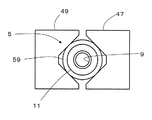
キャップ固定部23は、モータ35、37によって駆動され、第一キャップ5を両側から挟むようにして固定する構成となっている。キャップ固定部23の斜視図を図6に示す。この図に示されるように、別々のモータ35、37によって駆動される水平板43、45上に、第一キャップ5の先端を固定するための2枚のキャップ先端固定板47、49が鉛直にそれぞれ対向するように設けられている。これらのキャップ先端固定板47、49の対向面は、第一キャップ5を固定するための略台形形状の切り欠きが形成されている。
The
また、水平板43、45上には、キャップ先端固定板47、49と平行に、キャップ根元固定板51、53がそれぞれ対向配置されている。これらのキャップ根元固定板51、53にも略台形形状の切り欠きがそれぞれ形成されており、第一キャップ5の根元がこれらの切り欠きに受け入れられ、両側から挟むように固定される。
Further, on the
フランジ保持部27は、図5に示されるように、水平断面が略コ字形状である2枚の同一形状の板がそれぞれ溝を対向するようにしてベース33に対して垂直に設けられている。フランジ保持部27は、この溝に注射器3の注射筒19に設けられたフランジ25の両縁部を格納して注射筒19を保持する機能を有しているが、注射器3の長手方向の移動を規制すれば十分であり、この長手方向に対して垂直な方向を規制する必要はない。したがって、この実施例のフランジ保持部27は、モータなどによって可動しない構成となっている。
As shown in FIG. 5, the
押子保持部31は、フランジ保持部27の後段側のベース33に垂直に配置されている。ここで、本明細書において後段とは、より押子29のフランジ57側という意味を含む。押子保持部31には、注射器3の押子29の端部に設けられたフランジ57を受け入れる溝が形成されており、この溝に押子29のフランジ57を嵌め込ませ、モータ39を制御して注射筒19内で押子29を往復動作させる。これによって注射筒19内部の薬剤(図示せず)を出し入れさせる。
The
以上のような注射器保持機21の動作を、注射針保護具1を装着した注射器3を用いて説明する。まず、注射器3が注射器保持機21に固定されるまでの動作を説明する。
The operation of the
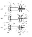
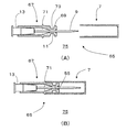
図7(A)、(B)、(C)は、注射器3が注射器保持機21に固定される動作を時系列で示しており、第一キャップ5、第二キャップ7およびキャップ固定部23は水平断面を示している。
7A, 7B, and 7C show the operation of fixing the
図7(A)は、注射器3が薬剤混合装置の注射器搭載機構によって注射器保持機21に搭載された後の様子を示すものである。注射筒19のフランジ25と押子29のフランジ57が、それぞれ押子保持部31およびフランジ保持部27の溝に嵌め込まれ、注射器3の長軸方向の動きが規制されるように保持されていている。この段階では、キャップ固定部23は開いた状態なので針管9は正確な位置に固定されていない。また、押子29は注射筒19に最も深く挿入された状態となっている。
FIG. 7A shows a state after the
その後、図7(B)に示されるように、図示しない薬剤混合装置の機構によって第二キャップ7が第一キャップ5から取り外される。
Thereafter, as shown in FIG. 7B, the
そして、図7(C)に示されるように、キャップ固定部23が動作して針管9を固定する。キャップ固定部23は、2つのモータ35、37によって注射針ユニット15の第一キャップ5の先端および根元を両側から挟みこむようにして第一キャップ5を固定している。
Then, as shown in FIG. 7C, the
より詳細には、支持部11との接続部分に近い円筒部59の前段部分を2枚のキャップ先端固定板47、49によって挟まれるように固定されている。このため、第一キャップ5の支持部11を介して針管9が注射器保持機21に対して固定される。
More specifically, the front portion of the
また、第一キャップ5の拡径の円筒部59の後段部分は、2枚のキャップ根元固定板51、53によって両側から挟まれるように固定される。これにより、さらに確実に針管9が注射器保持機21に対して固定される。
Further, the rear stage portion of the enlarged diameter
図8は、キャップ先端固定板47、49により第一キャップ5の円筒部59が固定された様子を示したものである。図に示されるように、円筒部59がキャップ先端固定板47、49の向かい合った略台形形状の切り欠きに挟まれることで、キャップ先端固定板47、49が円筒部59の外周の4点に作用し固定されている。
FIG. 8 shows a state in which the
ここで、注射器保持機21による保持力をより針管9に伝達させる観点から、キャップ先端固定板47、49によって保持される第一キャップ5の部位を支持部11とし、狭径の支持部11の外周を挟むように直接固定してもよい。
Here, from the viewpoint of transmitting the holding force by the
注射器3が搭載され、針管9が固定された注射器保持機21は、薬剤混合装置によって混合調製に用いられる。図9(A)は、混合調製の一部の例を示すもので、図示しないゴム栓が詰められたバイアル17の開口に対して針管9が垂直となるように、バイアル17が格納された容器保持機63と注射器保持機21とが対向するように配置された様子を示している。
The
この状態から、図9(B)に示されるように、注射器保持機21のベース33がモータ41によってバイアル17に近接し、針管9がゴム栓を穿刺する。その後、モータ41によって押子保持部31が注射器3の押子29を注射筒19から後退させ、バイアル17内の薬剤を注射筒19へ移動させる。この後は、モータ41によりベース33が図9(A)の位置に戻り、他のバイアル18内へ薬剤を注入させるなどの混合調製が行われる。
From this state, as shown in FIG. 9B, the
以上のように、この実施例の注射器3は、針基13側の針管9を保護し、注射器保持機21によって保持される第一キャップ5と、第一キャップ5によって保護されない残りの針管9を保護する第二キャップ7とを備え、第一キャップ5には針管9を外周から支持する支持部11を備えているので、注射筒19の筒先と針基13との接続および針基13と針管9の接続や、注射筒19、針基13などの製造に起因する誤差が生じていても、注射器保持機21やこれを含む薬剤混合装置に複雑な構成を施すことなく、注射器3の針先を薬剤容器17に正確に穿刺させることができる。
As described above, the
より具体的には、注射器保持機21のキャップ固定部23は、第一キャップ5を直接固定し、これによる保持力が支持部11の内壁55と密着している針管9に伝達するので、針管9を注射器保持機21に正確に固定することができる。これによって針先をバイアルなどの薬剤容器17の口に正確に挿入させることができる。
More specifically, the
また、第二キャップ7は第一キャップ5に着脱可能に接続されているので、作業の終了後、注射器3を薬剤混合装置から取り出す際に再び第二キャップ7を第一キャップ5に接続して保護することができる。これは、薬剤容器17から薬剤を注射筒19内に吸引し、これを患者に投与する場合に有益である。
Further, since the
(実施の形態2)
図10および図11は、第二の実施例の注射針保護具65を針管9および針基13を嵌め込んだ、注射針ユニット75として示している。図10は、針管9と針基13に装着した第一キャップ67と第二キャップ7を示し、図11は、図10の断面図を示している。ただし、針管9および針基13は断面ではなく正面を示している。ここで第一の実施例と同一の部材、構成には同一の符号を附し、その説明を省略する。
(Embodiment 2)
10 and 11 show the
第一実施例の注射針ユニット15と第二実施例の注射針ユニット75との違いは、第一キャップ67の構成である。すなわち、図10および図11に示されるように、この実施例の第一キャップ67の支持部11の先端には鍔部69が備えられている。また、支持部11より後段の第一キャップ67の円筒の外周には、第二キャップ7を第一キャップ67に嵌め込む際に、第二キャップ7の開口端を位置決めするためのリング部71が形成されている。
The difference between the
円筒形状の支持部11は、拡径の第一キャップ67よりも狭径であり、リング形状の鍔部69の外径は、第一キャップ67の拡径と同じになるように構成されている。したがって、第一キャップ67は支持部11においてリング状の溝73が形成されたような構成となっている。
The
ここで、注射器保持機21による第一キャップ67の支持は、キャップ固定部23のキャップ先端板47、49をこの溝73に嵌め込むことで行ってもよいし、第一実施例と同様に、第二キャップ7の開口端の位置決め用のリング部71と支持部11との間の拡径となっている箇所にキャップ先端板47、49を両側から挟んで針管9を固定してもよい。
Here, the support of the
この実施例では、第一実施例の作用効果に加え、次のような作用効果を奏する。すなわち、薬剤容器17に穿刺し、針管9に薬剤が付着する場合があっても、鍔部69が第一キャップ67の側面にさらに広がるのを防止する。このため、注射器保持機21のキャップ固定部23に薬剤が付着することがなく、衛生を保つことができる。また、リング部71は、第一キャップ67に第二キャップ7を接続する際、第二キャップ7の開口端がリング部71によって位置決めさせるだけでなく、鍔部69のバックアップの役割を担う。
In this embodiment, in addition to the functions and effects of the first embodiment, the following functions and effects are achieved. That is, even when the
本発明は、正確に穿刺する必要のある注射器に適用することができる。特に、自動で対象物に穿刺させる薬剤混合装置等の機器に用いられる注射器に適用できる。 The present invention can be applied to a syringe that needs to be accurately punctured. In particular, the present invention can be applied to a syringe used in a device such as a drug mixing device that automatically punctures an object.
1 注射針保護具
5 第一キャップ
7 第二キャップ
9 針管
11 支持部
13 針基
DESCRIPTION OF
Claims (8)
前記針基側の前記針管を保護するとともに、注射器保持機によって保持される第一キャップと、
前記第一キャップによって保護されない残りの前記針管を保護する第二キャップと、を備え、
前記第一キャップには、前記針管を外周から支持する支持部が備えられていることを特徴とする注射針保護具。 An injection needle protector that covers the needle tube connected to the needle base and protects the needle tube,
A first cap that protects the needle tube on the needle base side and is held by a syringe holder;
A second cap that protects the remaining needle tube that is not protected by the first cap;
The first needle cap is provided with a support portion for supporting the needle tube from the outer periphery.
Priority Applications (2)
| Application Number | Priority Date | Filing Date | Title |
|---|---|---|---|
| JP2010275332A JP2012120761A (en) | 2010-12-10 | 2010-12-10 | Injection needle protector, injection needle unit, and injector to which the injection needle unit is mounted |
| US13/311,696 US8545453B2 (en) | 2010-12-10 | 2011-12-06 | Injection needle protector, injection needle unit, and injector to which this injection needle unit is mounted |
Applications Claiming Priority (1)
| Application Number | Priority Date | Filing Date | Title |
|---|---|---|---|
| JP2010275332A JP2012120761A (en) | 2010-12-10 | 2010-12-10 | Injection needle protector, injection needle unit, and injector to which the injection needle unit is mounted |
Publications (2)
| Publication Number | Publication Date |
|---|---|
| JP2012120761A true JP2012120761A (en) | 2012-06-28 |
| JP2012120761A5 JP2012120761A5 (en) | 2014-01-30 |
Family
ID=46200089
Family Applications (1)
| Application Number | Title | Priority Date | Filing Date |
|---|---|---|---|
| JP2010275332A Pending JP2012120761A (en) | 2010-12-10 | 2010-12-10 | Injection needle protector, injection needle unit, and injector to which the injection needle unit is mounted |
Country Status (2)
| Country | Link |
|---|---|
| US (1) | US8545453B2 (en) |
| JP (1) | JP2012120761A (en) |
Families Citing this family (1)
| Publication number | Priority date | Publication date | Assignee | Title |
|---|---|---|---|---|
| CN105496781A (en) * | 2016-01-23 | 2016-04-20 | 潍坊市华星医疗器械有限公司 | Needle-slanting locking joint drug dissolving device |
Citations (1)
| Publication number | Priority date | Publication date | Assignee | Title |
|---|---|---|---|---|
| US5385550A (en) * | 1994-03-29 | 1995-01-31 | Su; Chan-Ho | Needle protective means for prevention against stab and virus infection |
Family Cites Families (15)
| Publication number | Priority date | Publication date | Assignee | Title |
|---|---|---|---|---|
| US4935016A (en) * | 1988-02-17 | 1990-06-19 | Deleo John | Syringe |
| US4892521A (en) * | 1988-08-03 | 1990-01-09 | Lincoln Mills, Inc. | Protective cover for hypodermic needle |
| US5403288A (en) * | 1992-02-13 | 1995-04-04 | Stanners; Sydney D. | Safety sleeve for dental syringe |
| US5209739A (en) * | 1992-06-23 | 1993-05-11 | Leon Talalay | Hypodermic needle |
| JPH074145B2 (en) | 1992-07-27 | 1995-01-25 | 禎美 伊藤 | Method of manufacturing edible container |
| US5540666A (en) * | 1993-03-31 | 1996-07-30 | Immuno Aktiengesellschaft | Cannula shield and injection syringe system |
| JPH08191893A (en) | 1995-01-19 | 1996-07-30 | Arita Kouso Kagaku Kenkyusho:Kk | Syringe with needle cover |
| US7241275B2 (en) * | 1999-10-14 | 2007-07-10 | Becton, Dickinson And Company | Intradermal needle |
| US6478780B1 (en) * | 1999-12-16 | 2002-11-12 | Jack W. Shields | Sharps shield for dental and medical needs |
| US20030105434A1 (en) * | 2001-11-30 | 2003-06-05 | Wei-Ting Chang | Protection cap assembly for syringes |
| US20060069347A1 (en) * | 2002-08-15 | 2006-03-30 | Besing Quent D | Safety syringe sealing system and method of use |
| GB0620117D0 (en) * | 2006-10-11 | 2006-11-22 | Liversidge Barry P | Safety needle pack |
| EP2094174B1 (en) | 2006-11-22 | 2010-05-19 | Health Robotics S.r.l. | Method and machine for manipulating toxic substances |
| CN102341140B (en) * | 2009-03-11 | 2013-09-25 | 泰尔茂株式会社 | Puncture needle assembly and medicinal liquid injection device |
| GB2472578A (en) * | 2009-08-10 | 2011-02-16 | Owen Mumford Ltd | Sheath removal device and needle protector |
-
2010
- 2010-12-10 JP JP2010275332A patent/JP2012120761A/en active Pending
-
2011
- 2011-12-06 US US13/311,696 patent/US8545453B2/en not_active Expired - Fee Related
Patent Citations (1)
| Publication number | Priority date | Publication date | Assignee | Title |
|---|---|---|---|---|
| US5385550A (en) * | 1994-03-29 | 1995-01-31 | Su; Chan-Ho | Needle protective means for prevention against stab and virus infection |
Also Published As
| Publication number | Publication date |
|---|---|
| US20120150124A1 (en) | 2012-06-14 |
| US8545453B2 (en) | 2013-10-01 |
Similar Documents
| Publication | Publication Date | Title |
|---|---|---|
| US6966897B2 (en) | Combined container-syringe and assembly method of the same | |
| EP0282545B1 (en) | Connector and a disposable assembly utilizing said connector | |
| EP0107873B1 (en) | Hypodermic syringe having a telescopic assembly between cartridge and medicament holder | |
| JP5536305B2 (en) | Method and apparatus for delivering a therapeutic agent through an injection port | |
| EP2543354A1 (en) | Medical device | |
| JP6002752B2 (en) | Sealing member for container | |
| JPS62197070A (en) | Syringe barrel and hypoderimic needle assembly | |
| JP7235743B2 (en) | A syringe holder for a medical syringe and a method of forming a medical syringe assembly | |
| US12383468B2 (en) | Pharmaceutical compounding system and method | |
| JP2014512912A (en) | Connector device | |
| JP5628201B2 (en) | Drug delivery device | |
| WO2014054183A1 (en) | Automatic preparation system | |
| EP3245999A1 (en) | Device for loading containers in dosing machines, adapter for the containers, support for the adapters and use thereof | |
| EP3176540B1 (en) | Syringe needle position and deviation correction method in a machine for the automatic preparation of intravenous medication | |
| EP3437681B1 (en) | Medicine administering apparatus, method of using medicine administering apparatus, and method for manufacturing medicine administering apparatus | |
| JP2012120761A (en) | Injection needle protector, injection needle unit, and injector to which the injection needle unit is mounted | |
| JP4095253B2 (en) | Syringe for both container and method for assembling the same | |
| KR20160061333A (en) | Assembly for coupling an adaptor with a medical container | |
| JP6391946B2 (en) | Chemical container | |
| JP3103274U (en) | Protective equipment for liquid transfer section | |
| JP7554271B2 (en) | A primary vessel assembly having an integral flow path | |
| JP3065673B2 (en) | Prefilled syringe | |
| JP2022051636A (en) | Device for handling syringe and automated device for preparing intravenous medication comprising that device for handling syringe | |
| HK40060312B (en) | Pharmaceutical compounding system and method | |
| HK40060312A (en) | Pharmaceutical compounding system and method |
Legal Events
| Date | Code | Title | Description |
|---|---|---|---|
| A521 | Written amendment |
Free format text: JAPANESE INTERMEDIATE CODE: A523 Effective date: 20131205 |
|
| A621 | Written request for application examination |
Free format text: JAPANESE INTERMEDIATE CODE: A621 Effective date: 20131205 |
|
| RD01 | Notification of change of attorney |
Free format text: JAPANESE INTERMEDIATE CODE: A7421 Effective date: 20140106 |
|
| A711 | Notification of change in applicant |
Free format text: JAPANESE INTERMEDIATE CODE: A711 Effective date: 20140129 |
|
| RD02 | Notification of acceptance of power of attorney |
Free format text: JAPANESE INTERMEDIATE CODE: A7422 Effective date: 20140129 |
|
| A977 | Report on retrieval |
Free format text: JAPANESE INTERMEDIATE CODE: A971007 Effective date: 20140926 |
|
| A131 | Notification of reasons for refusal |
Free format text: JAPANESE INTERMEDIATE CODE: A131 Effective date: 20140930 |
|
| A711 | Notification of change in applicant |
Free format text: JAPANESE INTERMEDIATE CODE: A711 Effective date: 20141028 |
|
| A02 | Decision of refusal |
Free format text: JAPANESE INTERMEDIATE CODE: A02 Effective date: 20150217 |