JP2012123725A - Control lever of work machine - Google Patents
Control lever of work machine Download PDFInfo
- Publication number
- JP2012123725A JP2012123725A JP2010275762A JP2010275762A JP2012123725A JP 2012123725 A JP2012123725 A JP 2012123725A JP 2010275762 A JP2010275762 A JP 2010275762A JP 2010275762 A JP2010275762 A JP 2010275762A JP 2012123725 A JP2012123725 A JP 2012123725A
- Authority
- JP
- Japan
- Prior art keywords
- mass
- shaft portion
- operation lever
- dynamic vibration
- vibration absorber
- Prior art date
- Legal status (The legal status is an assumption and is not a legal conclusion. Google has not performed a legal analysis and makes no representation as to the accuracy of the status listed.)
- Pending
Links
Images


Landscapes
- Mechanical Control Devices (AREA)
- Operation Control Of Excavators (AREA)
- Component Parts Of Construction Machinery (AREA)
Abstract
Description
本発明は、例えば油圧ショベル等の作業機械の操作手段として設けられる操作レバーに関するものである。 The present invention relates to an operation lever provided as an operation means for a work machine such as a hydraulic excavator.
油圧ショベル等の作業機械は、油圧ポンプを備えており、この油圧ポンプにより油圧シリンダや油圧モータからなる油圧アクチュエータが駆動されることになる。油圧ポンプは複数の油圧アクチュエータを動作させるものであり、各油圧アクチュエータはコントロールバルブを介して油圧ポンプと接続されており、また各油圧アクチュエータからの戻り油はコントロールバルブを介して作動油タンクに還流される。 A working machine such as a hydraulic excavator includes a hydraulic pump, and a hydraulic actuator including a hydraulic cylinder and a hydraulic motor is driven by the hydraulic pump. The hydraulic pump operates multiple hydraulic actuators. Each hydraulic actuator is connected to the hydraulic pump via a control valve, and the return oil from each hydraulic actuator is returned to the hydraulic oil tank via the control valve. Is done.
油圧ショベル等が備えている油圧回路は概略以上のようなものであり、コントロールバルブの作動を制御するために、通常、運転室における運転席の前方位置には走行用レバーが設けられ、また左右両側には操作レバーが設けられ、これらはオペレータが手動で操作することになる。操作レバーは、運転席の左右にそれぞれ1本設けられ、操作レバーを左右方向や前後方向に傾動させることによりコントロールバルブの切換操作が行われる。コントロールバルブの制御が油圧パイロット方式で行われる場合には、操作レバーがパイロットバルブに接続して設けられ、操作レバーの操作により油圧源としてのパイロットポンプからの油圧パイロット圧がコントロールバルブを構成する方向切換弁の両端に設けたパイロット室のいずれかに供給されて、この方向切換弁が切り換わることになる。 The hydraulic circuit provided in a hydraulic excavator or the like is as described above. In order to control the operation of the control valve, a traveling lever is usually provided at the front position of the driver's seat in the cab, and Operation levers are provided on both sides, and these are manually operated by an operator. One operation lever is provided on each of the left and right sides of the driver's seat, and the control valve is switched by tilting the operation lever in the left-right direction or the front-rear direction. When the control valve is controlled by a hydraulic pilot system, the operation lever is connected to the pilot valve, and the hydraulic pilot pressure from the pilot pump as the hydraulic source is configured by the operation of the operation lever. The directional switching valve is switched by being supplied to one of the pilot chambers provided at both ends of the switching valve.
パイロットバルブの具体的構成は特許文献1等に開示されている。パイロットバルブは、コントロールバルブのパイロット室とパイロットポンプとの間に設けたパイロット流路の接続・遮断を行うためのものである。従って、パイロットバルブは流路を開閉するためのスプールを備えており、スプールには復帰ばねが作用している。また、スプールを復帰ばねに抗して押し込むためにプッシャが設けられている。常時においては、スプールは復帰ばねの作用でパイロットポンプとパイロット室との間が連通するのを遮断しており、プッシャを復帰ばねに抗して押し込むと、パイロットポンプとパイロット室との間が接続されて、パイロット室内にパイロット圧が作用して、方向切換弁が切り換わることになる。操作レバーは、パイロットバルブのケーシングに枢支されており、操作レバーの枢支部近傍にはカム部材が装着されている。従って、操作レバーを傾動させると、カム部材でプッシャが復帰ばねに抗して押し込まれて、制御対象となる方向切換弁のパイロット室に連通しているパイロット流路がパイロットポンプと接続される結果、その方向切換弁が切り換わることになる。 A specific configuration of the pilot valve is disclosed in Patent Document 1 and the like. The pilot valve is for connecting / blocking a pilot flow path provided between the pilot chamber of the control valve and the pilot pump. Therefore, the pilot valve has a spool for opening and closing the flow path, and a return spring acts on the spool. A pusher is provided to push the spool against the return spring. At normal times, the spool blocks the communication between the pilot pump and the pilot chamber by the action of the return spring. When the pusher is pushed against the return spring, the connection between the pilot pump and the pilot chamber is established. Thus, the pilot pressure acts in the pilot chamber, and the direction switching valve is switched. The operation lever is pivotally supported by the casing of the pilot valve, and a cam member is mounted in the vicinity of the pivot portion of the operation lever. Therefore, when the operating lever is tilted, the pusher is pushed against the return spring by the cam member, and the pilot flow path communicating with the pilot chamber of the direction switching valve to be controlled is connected to the pilot pump. The direction switching valve is switched.
ところで、操作レバーは運転席に着座しているオペレータが手動で前後及び左右に傾動操作するものであり、運転席の左右いずれか一方若しくは双方にコンソールボックスを設けられ、このコンソールボックスに操作レバーが装着されるのが一般的である。操作レバーはパイロットバルブのケーシングから大きく突出させており、真っ直ぐ上方に、または斜め上方に延在させるようにするか、または途中で曲成したものもある。そして、操作レバーの操作性等を勘案して、その高さや角度等が設定されることになる。 By the way, the operator lever seated in the driver's seat is manually tilted back and forth and left and right, and a console box is provided on either the left or right side of the driver's seat. It is common to install. The operation lever protrudes greatly from the casing of the pilot valve, and may extend straight upward, obliquely upward, or bend in the middle. And the height, angle, etc. are set in consideration of the operability of the operation lever.
作業機械の作動中には振動が発生することになり、この振動が操作レバーにも伝達される。操作レバーの基端部はパイロットバルブのケーシングに枢支されており、その先端部は自由状態となっている。従って、作業機械が稼働中は、継続的に振動することになり、その振動が操作レバーに伝達されて、この操作レバーが枢支部を中心として揺動することになる。従って、共振により操作レバーが大きく揺動することになるが、この操作レバーの動きに追従してプッシャが押し込まれる。その結果、方向切換弁のパイロット室にパイロット圧が作用して、方向切換弁が切り換わることになり、油圧アクチュエータの安定性が損なわれることがある。このような事態の発生を防止するために、通常は、操作レバーに所定範囲の無効ストローク(遊び)を持たせて、操作レバーがある程度まで傾けても、無効ストローク分はスプールが切り換わらないように設定している。 Vibration is generated during operation of the work machine, and this vibration is also transmitted to the operation lever. The base end portion of the operation lever is pivotally supported by the pilot valve casing, and the distal end portion thereof is in a free state. Therefore, while the work machine is in operation, it vibrates continuously, the vibration is transmitted to the operation lever, and the operation lever swings around the pivot portion. Therefore, although the operation lever swings greatly due to resonance, the pusher is pushed in following the movement of the operation lever. As a result, the pilot pressure acts on the pilot chamber of the direction switching valve to switch the direction switching valve, which may impair the stability of the hydraulic actuator. In order to prevent such a situation from occurring, normally, even if the operating lever has a predetermined range of invalid stroke (play) and the operating lever is tilted to some extent, the spool does not switch for the invalid stroke. Is set.
油圧ショベル等の作業機械においては、不整地走行時や作業時等においては、旋回フレームにピッチング振動やローリング振動、さらには並進振動、ねじれ振動等が発生することになり、これらの振動は極めて大きいものとなることがある。この振動は、当然、操作レバーにも伝達されることになり、作用する振動の大きさによっては、操作レバーが無効ストローク分を越えるまで大きく揺動することもある。無効ストロークをこのような範囲まで広げると、この操作レバーの操作性が低下することになり、望ましいものではない。従って、無効ストロークを持たせるにしろ、この無効ストロークを大きくするのには限度がある。 In working machines such as hydraulic excavators, pitching vibrations, rolling vibrations, translational vibrations, torsional vibrations, etc. occur in the swing frame when traveling on rough terrain or during work, and these vibrations are extremely large. It can be a thing. Naturally, this vibration is also transmitted to the operation lever, and depending on the magnitude of the acting vibration, the operation lever may swing greatly until it exceeds the invalid stroke. If the invalid stroke is extended to such a range, the operability of the operation lever is lowered, which is not desirable. Therefore, even if an invalid stroke is provided, there is a limit to increasing the invalid stroke.
以上のことから、例えば、油圧ショベルが不整地を走行する際には、オペレータは走行レバーを握り、フロント操作レバーを握らない状態となることから、フロント操作レバーは自由振動状態となり、油圧ショベルに加わる振動により操作レバーが大きく揺動することになって、カム部材によりスプールが押し込まれるのを避けることはできない。その結果、意図しない作業手段の動作や旋回動作が生じるおそれがある。特に、操作レバーの操作性の観点から、操作レバーはシャフト部の先端にグリップ部を設けたものから構成するが、シャフト部は細径のものとし、先端側のグリップ部をオペレータが握り易いものとするために、シャフト部に太径のグリップ部を嵌合させて設けるようにする。このために、基端側と比較して、先端が重量化することになり、操作レバーの振動による揺動角が前述した無効ストロークを越える可能性がさらに高くなってしまう。 From the above, for example, when the excavator travels on rough terrain, the operator grips the travel lever and does not grip the front operation lever. It is inevitable that the spool is pushed by the cam member because the operating lever swings greatly due to the applied vibration. As a result, there is a risk of unintended operation of the working means and turning operation. In particular, from the viewpoint of operability of the operating lever, the operating lever is composed of a shaft provided with a grip at the tip, but the shaft is of a small diameter so that the operator can easily grip the grip on the tip. In order to achieve this, a large diameter grip portion is fitted to the shaft portion. For this reason, the tip is heavier than the base end side, and the possibility that the swing angle caused by the vibration of the operation lever exceeds the above-described invalid stroke is further increased.
また、スプールに作用させている復帰ばねのばね力を大きくすれば、操作レバーの耐振動性が向上し、その安定性を確保でき、意図しない作動を防止できる。しかしながら、スプールの切り換え操作はこの復帰ばねの付勢力に抗して操作レバーを傾動させる操作を行うものであるから、復帰ばねの付勢力を大きくすると、パイロットバルブの切換操作の操作性が悪くなってしまうという問題点もある。 Further, if the spring force of the return spring acting on the spool is increased, the vibration resistance of the operation lever is improved, the stability thereof can be ensured, and the unintended operation can be prevented. However, since the switching operation of the spool is an operation of tilting the operation lever against the biasing force of the return spring, if the biasing force of the return spring is increased, the operability of the pilot valve switching operation is deteriorated. There is also a problem that it ends up.
本発明は以上の点に鑑みてなされたものであって、その目的とするところは、作業機械に大きな振動が発生しても、この振動に追従する操作レバーの動きを最小限に抑制できるようにすることにある。 The present invention has been made in view of the above points, and an object of the present invention is to suppress the movement of the operation lever following the vibration to a minimum even when a large vibration is generated in the work machine. Is to make it.
前述した目的を達成するために、本発明は、シャフト部と、このシャフト部の先端に設けたグリップ部とからなり、パイロットバルブユニットに設けられ、傾動操作することによって、前記パイロットバルブユニットの弁部材を作動させて、油圧源と方向切換弁のパイロット部との間を連通・遮断させる操作レバーであって、前記シャフト部には、質量とばね性部材とからなり、このばね性部材を前記シャフト部に連結して設けることによって、前記質量を前記シャフト部の軸線と交差する方向に振動可能した動吸振器が装着される構成としたことをその特徴とするものである。 In order to achieve the above-mentioned object, the present invention comprises a shaft portion and a grip portion provided at the tip of the shaft portion. An operating lever for operating and disconnecting a hydraulic pressure source and a pilot portion of the direction switching valve, wherein the shaft portion includes a mass and a spring member, and the spring member is The present invention is characterized in that a dynamic vibration absorber capable of vibrating the mass in a direction intersecting the axis of the shaft portion by being connected to the shaft portion is mounted.
操作レバーは作業機械、例えば不整地において、土砂の掘削等の作業をする油圧ショベルの運転室に装着されるものであって、作動時には操作レバーに振動が伝達され、しかも振動が継続することにより共振現象を生じることになる。なお、油圧ショベル以外であっても、油圧クレーン、ホイールローダ等といった自走式の作業機械にも設けることができる。 The operation lever is installed in the cab of a hydraulic excavator that performs work such as excavation of earth and sand on a work machine, such as rough terrain. Vibrations are transmitted to the operation lever during operation, and the vibration continues. A resonance phenomenon will occur. In addition, even if it is not a hydraulic shovel, it can also provide in self-propelled working machines, such as a hydraulic crane and a wheel loader.
動吸振器は質量とばね性部材とから構成されるが、質量は重量物、例えば鋼鉄等といった重量の金属部材で構成することができる。また、ばね性部材は、ゴム等の弾性部材や、板ばね,コイルばね等のばね類から構成することもできる。質量には透孔が設けられており、ばね性部材はこの質量の透孔における内周側に装着される。この動吸振器により吸収可能な振動数は質量の重量とばね性部材のばね定数により決定される。操作レバーはシャフト部とグリップ部とから構成されるものであり、動吸振器は操作レバーの操作の邪魔にならないようにするためにシャフト部に設けられる。シャフト部の基端部は、通常、パイロットバルブユニットのケーシングに枢支させるようにしており、動吸振器はこの枢支部からできるだけ離れた位置、好ましくはグリップ部に近接した位置に設けることになる。 The dynamic vibration absorber is composed of a mass and a spring member, but the mass can be composed of a heavy metal member such as steel. The spring-like member can also be composed of an elastic member such as rubber, or a spring such as a leaf spring or a coil spring. The mass is provided with a through hole, and the spring member is mounted on the inner peripheral side of the mass through hole. The frequency that can be absorbed by the dynamic vibration absorber is determined by the weight of the mass and the spring constant of the spring member. The operation lever is composed of a shaft portion and a grip portion, and the dynamic vibration absorber is provided on the shaft portion so as not to obstruct the operation of the operation lever. The base end portion of the shaft portion is normally pivotally supported by the casing of the pilot valve unit, and the dynamic vibration absorber is provided at a position as far as possible from the pivotally supported portion, preferably close to the grip portion. .
動吸振器をシャフト部に装着するために、質量の透孔の内周面に設けられるばね性部材はこの透孔内面に固定して設けるようになし、ばね性部材がシャフト部に対して固定的に保持される。ばね性部材を直接シャフト部に固定することも可能であるが、取付リングを用いて、この取付リングの外周面にばね性部材を装着するようになし、取付リングをシャフト部に着脱可能に固定する構成とするのが望ましい。ばね性部材の取付リング及び質量への連結は着脱可能であっても、また固着するようにしても良い。固着する場合には、接着剤を用いて行うことができるが、ばね性部材を板ばねで構成している場合には、溶着等の手段により固着することもでき、さらに取付リングの外周面にスリットを設けて、板ばねからなるばね性部材の端部を差し込むようにすることもできる。 In order to attach the dynamic vibration absorber to the shaft portion, the spring member provided on the inner peripheral surface of the mass through hole is fixed to the inner surface of the through hole, and the spring member is fixed to the shaft portion. Retained. Although it is possible to fix the spring member directly to the shaft part, it is possible to attach the spring member to the outer peripheral surface of this mounting ring using the mounting ring, and detachably fix the mounting ring to the shaft part. It is desirable to adopt a configuration to do so. The connection of the spring-like member to the attachment ring and the mass may be detachable or may be fixed. In the case of fixing, it can be performed using an adhesive, but when the spring-like member is constituted by a leaf spring, it can be fixed by means such as welding and further on the outer peripheral surface of the mounting ring. A slit may be provided so that the end of a spring-like member made of a leaf spring is inserted.
不整地の走行時や土砂の掘削作業等の作業時には、振動がシャフト部及びグリップ部からなる操作レバーに伝達されて、その枢支部を中心として揺動することになり、共振によりさらに大きく揺動する。動吸振器は主振動系として、操作レバーの枢支部を中心とした揺動を抑制するものであるから、質量はシャフト部の軸線と交差する方向、望ましいくはシャフト部の軸線と直交する方向に振動させることによって、有効な吸振機能を発揮することになる。質量がシャフト部の軸線方向または軸線に対する浅い角度方向に動くのは、吸振機能の点で望ましくはない。このために、取付リングの両端には前記質量の前記シャフトの軸線方向への動きを制限するストッパを設ける構成とすることができる。 When traveling on rough terrain or when excavating earth and sand, the vibration is transmitted to the operating lever consisting of the shaft and grip, and swings around the pivot, further swinging due to resonance. To do. Since the dynamic vibration absorber is a main vibration system and suppresses swinging around the pivot of the operation lever, the mass is in the direction intersecting the axis of the shaft, preferably in the direction perpendicular to the axis of the shaft. An effective vibration absorbing function will be exhibited by vibrating it. It is not desirable in terms of the vibration absorbing function that the mass moves in the axial direction of the shaft portion or in a shallow angle direction with respect to the axial line. For this reason, it can be set as the structure which provides the stopper which restrict | limits the movement to the axial direction of the said shaft of the said mass in the both ends of an attachment ring.
作業機械として、例えば油圧ショベルの運転室には、通常、運転席の左右両側にコンソールが設けられ、操作レバーはこのコンソールに装着されるが、操作性の観点から、操作レバーは運転席に着座したオペレータ側に向けて傾斜するように配置する構成としたものがある。この場合には、操作レバーは重力方向、つまり下方に荷重が作用することから、揺動に方向性がある。このような場合には、質量を偏心させるように対処することができる。例えば下方に曲成されている際には、質量の重心位置は斜め上方の位置になる。 As a work machine, for example, in a driver's cab of a hydraulic excavator, a console is usually provided on both the left and right sides of the driver's seat, and an operation lever is attached to this console. Some of them are arranged so as to be inclined toward the operator side. In this case, the operating lever is directional in the direction of gravity, that is, because the load acts downward. In such a case, measures can be taken to decenter the mass. For example, when it is bent downward, the center of gravity of the mass is a diagonally upward position.
パイロットバルブにおいて、操作レバーにより操作される弁部材はケーシング上面から突出するようにして装着される。このために、弁部材とその摺動部との間に塵埃等の異物が侵入するのを防止するために、パイロットバルブの上面から操作レバーにおけるシャフト部までの部位に蛇腹構造等、可撓性部材からなるブーツが装着されるのが一般的である。この場合には、動吸振器はブーツの内部に設けるようにするのが、外観等の見地から望ましい。 In the pilot valve, the valve member operated by the operation lever is mounted so as to protrude from the upper surface of the casing. For this reason, in order to prevent foreign matter such as dust from entering between the valve member and its sliding portion, a flexible structure such as a bellows structure is provided between the upper surface of the pilot valve and the shaft portion of the operation lever. Generally, a boot made of a member is attached. In this case, it is desirable from the viewpoint of appearance and the like that the dynamic vibration absorber is provided inside the boot.
作業機械に大きな振動が発生しても、この振動に追従して操作レバーが動くのを最小限に抑制することができ、操作レバーの揺動が規制されて、意図しない作動、つまり意図しない旋回動作や作業手段の動き等が発生するおそれが少なくなる。 Even if a large vibration occurs in the work machine, it is possible to minimize the movement of the operating lever following this vibration, and the swinging of the operating lever is restricted, causing unintended operation, that is, unintentional turning. There is less risk of movement or movement of the working means.
以下、図面に基づいて本発明の実施の形態について説明する。まず、図1に建設機械の一例として、油圧ショベルの全体構成を示す。図中において、1は下部走行体、2は上部旋回体、3は下部走行体1と上部旋回体2との間に設けた旋回装置である。上部旋回体2には、オペレータが着座して機械の操作を行うための運転室4が設けられ、また作業手段5が装着されている。作業手段5はブーム6,アーム7及びフロントアタッチメントとしてのバケット8から構成される。
Hereinafter, embodiments of the present invention will be described with reference to the drawings. First, FIG. 1 shows an overall configuration of a hydraulic excavator as an example of a construction machine. In the figure, 1 is a lower traveling body, 2 is an upper revolving body, and 3 is a revolving device provided between the lower traveling body 1 and the upper revolving
下部走行体1による走行、旋回装置3による上部旋回体2の旋回は、それぞれ油圧モータにより駆動されるものである。また、ブーム6,アーム7及びバケット8はそれぞれ油圧シリンダからなるブームシリンダ6a,アームシリンダ7a及びバケットシリンダ8aにより駆動される。これらの油圧モータや油圧シリンダは油圧アクチュエータとして、それぞれ一対からなる入出力ポートが設けられている。そして、一方のポートに圧油を供給し、他方のポートを戻り側とすることにより駆動されるものである。
The traveling by the lower traveling body 1 and the turning of the
このために、油圧アクチュエータの入出力ポートは、図2に示したように、コントロールバルブ10を介して油圧ポンプ11と、作動油タンク12とに切り換え可能に接続される。コントロールバルブ10は油圧パイロット方式で切り換わるものであり、このコントロールバルブ10の両油圧パイロット部10L,10Rにはそれぞれ油圧パイロット配管13L,13Rが接続されている。そして、油圧パイロット配管13L,13Rの一方をパイロットポンプ14に接続し、他方を作動油タンク12に接続することによりコントロールバルブ10の切り換え制御が行われる。
For this reason, the input / output port of the hydraulic actuator is connected to the
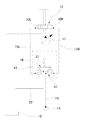
前述したコントロールバルブ10の切り換え制御を行うために、運転室4内にはパイロットバルブ装置15が設けられている。パイロットバルブ装置15は、図3に示したように、操作手段16とバルブユニット17とから構成されるものであって、バルブユニット17のバルブケーシング18には、出力配管として前述した油圧パイロット配管13L,13Rが接続されている。また、バルブユニット17にはパイロットポンプ14からの油圧配管19と、作動油タンク12への戻り配管20とが接続されており、操作手段16を操作すると、パイロット配管13L,13Rの一方がバルブユニット17に接続した油圧配管19と接続され、他方は戻り配管20と接続されている結果、コントロールバルブ10の油圧パイロット部10L,10R間に差圧が生じて、コントロールバルブ10が切り換わることになる。
In order to perform the switching control of the
パイロットバルブ装置15は、フロント操作レバー用のものであって、運転室における運転席の側部に設けたコンソールカバー21に設けられる。パイロットバルブ装置15を構成するバルブユニット17はコンソールカバー21より下方に配置されており、操作手段16はコンソールカバー21から突出している。バルブユニット17のバルブケーシング18には、左右に弁室22,22が設けられており、両弁室22にはスプール23が摺動可能に装着されている。弁室22には高圧側となる油圧配管19が接続されている油圧ポート24と、戻り配管20に接続した低圧ポート25とが設けられており、スプール23は出力ポート26を低圧ポート25と油圧ポート24との間に切り換えるためのものである。このために、スプール23は復帰ばね27による付勢力によって、両出力ポート26は共に低圧ポート25に接続された状態となっており、いずれか一方のスプール23が復帰ばね27の付勢力に抗して下方に押し込まれると、出力ポート26が油圧ポート24と接続されて、油圧パイロット信号がコントロールバルブ10における油圧パイロット部10Lまたは10Rのいずれかに供給される。
The
復帰ばね27はばね受け28に作用しており、このばね受け28にはスプール23に連結した連結ロッド23aの先端部が取り付けられている。ばね受け28にはプッシャ29が当接している。バルブユニット17を構成するバルブケーシング18の上端部には弁端板30が連結して設けられており、プッシャ29は弁端板30の表面から上方に突出している。そして、この弁端板30がコンソールカバー21に取り付けられて、このコンソールカバー21にパイロットバルブ装置15が固定されている。前述したバルブユニット17における流路の切り換えはいずれかのプッシャ29を押し込むことにより行われるものである。なお、弁室22及びスプール23、さらにはプッシャ29等からなるバルブユニット17は前後及び左右に2組、合計で4組設けられている。
The
バルブユニット17の操作を行う操作手段16は、プッシャ29を押し込んで、弁室22内でスプール23を摺動変位させるためのものである。このために、操作手段16はフロント操作用の操作レバー31を有し、操作レバー31はシャフト部32に、オペレータが手で把持して操作を行うためのグリップ部33を設けている。この操作レバー31のシャフト部32の基端側位置にはカム部34が設けられており、このカム部34のカム面34aはプッシャ29の先端部と当接している。カム部34で4箇所設けたプッシャ29のいずれかを押動操作するために、操作レバー31は弁端板30に左右及び前後に傾動可能に支承されており、このために弁端板30から突出するようにして枢支部35が設けられ、この枢支部35にユニバーサルジョイント36を介して操作レバー31及びカム部34からなる操作手段16が連結されている。
The operating means 16 for operating the
パイロットバルブ装置15がコンソールカバー21に装着された状態では、上方に突出したユニバーサルジョイント36や、カム部34とプッシャ29との当接部を覆うようになし、かつプッシャ29の弁端板30から突出させた部位にはシール部材37が装着されているが、この部位のシール性をより高くするために気密構造とする。このために、操作レバー31のグリップ部33とシャフト部32との境界部から弁端板30までの間にはブーツ38が装着されて、このブーツ38の内部が密閉される。ブーツ38はゴム等のばね性部材から構成された蛇腹構造のものである。
In a state where the
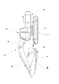
図4から明らかなように、シャフト部32に連結されているグリップ部33は、プラスチックやゴム等の部材で構成した握り部33aと芯材33bとから構成されており、ブーツ38の先端はこの握り部33aと芯材33bとの間に差し込まれている。芯材33bにはねじ孔が設けられており、シャフト部32の先端部分はこのねじ孔に螺挿されることになる。シャフト部32には、その先端近傍、つまりグリップ部33に近接した位置に動吸振器40が装着されている。
As is clear from FIG. 4, the
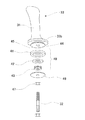
動吸振器40は、図5から明らかなように、質量41と弾性部材42とから構成されており、質量41は所定の重量を有するリング状の部材、例えば金属材からなり、弾性部材42は例えばゴム等からなり、やはり円環状に形成されている。そして、主振動系を構成する操作レバー31の固有振動数とほぼ等しくなるように、質量41の重量と弾性部材42のばね定数を設定することによって、動吸振器40の振動は操作レバー31に伝達される車両の振動とのつりあいによって、この操作レバー31が揺動するのを防止乃至抑制することができる。
As is clear from FIG. 5, the
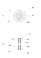
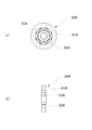
図5(a)は動吸振器40の平面図であり、図5(b)はその中心位置を含む縦断面図である。動吸振器40における質量41は外周側に位置し、弾性部材42は内周側に位置するものであり、これら質量41と弾性部材42との間は接着等の手段により固着されている。そして、弾性部材42の内周面は取付リング43の外周面に接着等の手段で固着され、取付リング43はシャフト部32に着脱可能に固定されることになる。動吸振器40はブーツ38の内部に配置されており、その取付リング43がシャフト部32に装着されている。取付リング43の上下の位置には、上下のストッパ45,46が設けられており、取付リング43は上下のストッパ45,46間に挟持されている。そして、シャフト部32におけるストッパ45,46の下方位置にはナット47が螺挿されており、取付リング43及び両ストッパ45,46はナット47によりグリップ部33に固定的に保持されるようになっている。
Fig.5 (a) is a top view of the
上部側のストッパ45は、グリップ部33の芯材33bと一体に設けるか、または別部材として構成することになる。そして、ナット47をシャフト部32に螺挿しておき、ストッパ46及び動吸振器40を順次シャフト部32に螺合させ、この状態でシャフト部32の先端をグリップ部33の芯材33bに螺入することによって、動吸振器40を組み込んだ状態でシャフト部32とグリップ部33とが連結される。ここで、シャフト部32と取付リング43との間は螺合しており、これによって動吸振器40のシャフト部32への取り付け部はがたつくおそれがなくなる。なお、動吸振器40は、その質量41が多少の隙間を介してではあるが、ストッパ45,46間に配置されており、質量41と弾性部材42との間及び弾性部材42と取付リング43との間の接着剤が劣化しても、シャフト部32から脱落するおそれはない。
The
動吸振器40は、操作レバー31が振動したときに、この操作レバー31の振動に共振させることによって、操作レバー31の振動を抑制するためのものである。この操作レバー31の振動を有効に抑制するには、操作レバー31の全長と全重量との関係で、質量41の重量とばね性部材としての弾性部材42のばね定数とを適宜設定する必要がある。そして、操作レバー31の動きは枢支部35を中心とした揺動となるので、動吸振器40における質量41の振動方向としては、シャフト部32の軸線と概略直交する方向乃至それから多少の角度を持った方向に限定することによって、より高い振動吸収機能を発揮することになる。
The
ストッパ45,46はこの質量41の動きをシャフト部32の軸線とほぼ直交する方向に限定するためのものであり、ストッパ45,46と質量41との間には、僅かに隙間を持った状態とすることによって、可動範囲を限定する。ただし、取付リング43の上下の端部には所定の厚みを有するフランジ部43a,43aが形成されており、従って弾性部材42はストッパ45,46に対して非接触状態に保たれ、質量41の動きがストッパ45,46により制限されるのを防止している。
The
油圧ショベルが作動中は、上部旋回体2の全体が振動することになり、この振動が操作レバー31に伝達されて、枢支部35を中心として先端側が揺動し、共振作用により大きく揺動することになる。操作レバー31におけるシャフト部32には動吸振器40が装着されており、操作レバー31の揺動に追従して、動吸振器40を構成する質量41がシャフト部32の軸線と交差する方向に振動することになる結果、主振動系を構成する操作レバー31の揺動が抑制される。従って、意図しないにも拘わらず、いずれかの油圧アクチュエータが作動してしまう等といった事態が発生することはない。
While the hydraulic excavator is in operation, the entire
このように、操作レバー31の吸振機能を発揮させるために、動吸振器40を設けているが、この動吸振器40は操作レバー31のシャフト部32の周囲に装着される小型でコンパクトな構造のものであることから、操作レバー31全体として格別大型化することはない。しかも、動吸振器40はブーツ38の内部に設けられており、外部に露出していないので、操作レバー31の振動吸収機構を設けないものと外観上差異はない。
As described above, the
ところで、シャフト部32はその全体が真っ直ぐな棒状部材とすることもできるが、運転席に着座して行われる操作レバー31の操作性を考慮して、図3に示したように、グリップ部33を傾斜させている。このために、シャフト部32には、その中間位置で曲げられており、基端側から途中までの部位は鉛直部32aとなり、この鉛直部32aから傾斜部32bとなる。に曲げ部が形成されており、この曲げ部Bより基端側は真っ直ぐ延在されて、枢支部35に枢着されている。従って、シャフト部32の先端側に連結されているグリップ部33は運転席に着座しているオペレータの手前側に向けて先端側が立ち上がるように曲っており、グリップ部33の操作に対する負担軽減を図っている。
By the way, although the
このように、鉛直部32aと傾斜部32bとからなるシャフト部32を有する操作レバー31にあっては、その重心位置は、この操作レバー31の揺動中心となる枢支部35の鉛直線の位置から偏寄した位置となっている。従って、油圧ショベルが稼働中には、操作レバー31はグリップ部33がより傾く方向、つまり重力方向には振れ幅が大きく、それとは反対方向、つまり反重力方向の振れ幅は小さいものとなる。このために、動吸振器を構成する質量とばね性部材とを取付リングに対して同心円とするのではなく、偏心させるようにする。
Thus, in the
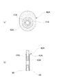
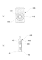
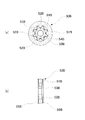
図6(a),(b)に示した動吸振器40Aは、楕円形状とした質量41Aを用いて、その中心から長手方向に偏寄した位置に透孔を形成して、その内部に前述した第1の実施の形態で示したと同様の弾性部材42Aを接着手段で固着する。そして、弾性部材42Aは取付リング43Aの外周面に固着して設けるようにする。また、図7(a),(b)に示した動吸振器40Bは、平面状態では長方形で、所定の厚みを有する質量41Bを用い、この質量41Bには長手方向に偏寄した位置に取付リング43Bに連結されている弾性部材42Bを装着するための透孔を形成する。
The
動吸振器40A,40Bは、それらの質量41A,41Bの突出している側を反重力方向、つまり上方を向けた状態にしてシャフト部32における傾斜部32bに固定される。これによって、操作レバー31の揺動時に、下方に向けて倒れる方向の動きに対して、質量41A,41Bが振動する際に、反重力方向に慣性力が作用することになるので、曲げを有する操作レバー31に対して高い振動吸収機能を発揮させることができる。
The
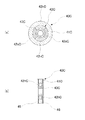
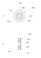
油圧ショベルの作動時には、運転室4を設けた上部旋回体2は様々な方向に振動する。具体的には、ピッチング振動やローリング振動、さらには並進振動、ねじれ振動等といったものである。そして、カム部34のカム面34aが当接しているプッシャ29は4箇所設けられている。従って、操作レバー31は左右及び前後の各方向に揺動するものであって、しかも揺動方向及び揺動時に作用する慣性力等が方向によっては異なってくる。例えば、土砂の掘削時に作用するピッチング振動は振動の振幅が大きく、ローリング振動は振幅が比較的小さく、また両者は振動の周波数も異なる。ピッチング振動は主に上部旋回体2の前後方向に作用するものであり、ローリング振動は主に上部旋回体2の左右方向に作用するものである。そこで、図8(a),(b)に示したように、動吸振器40Cとして、質量41Cの大きさや形状はともかく、この質量41Cと取付リング43Cとの間に設けられる弾性部材42Cを、概略90度分の円弧状のピースを連結して円環状に形成したものを用いることができる。そして、弾性部材42Cを構成する各ピースのばね定数を変えるようにする。図中において、円弧状ピース42hCはばね定数の大きい硬質ピースであり、円弧状ピース42sCはばね定数の小さい軟性ピースとしたものが示されている。例えば、比較的高い周波数で上下に振動するピッチング振動時に対しては、上下のピースを硬質ピース42hCから構成し、比較的低い周波数で水平方向に振動するローリング振動に対しては、左右のピースを軟性ピース42sCとする。これによって、作用する振動の性質に応じて動吸振器40に最適なばね定数を持たせることができる。
When the hydraulic excavator is operated, the
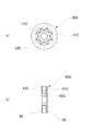
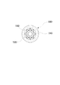
前述した各実施の形態では、動吸振器を構成するばね性部材としては、ゴム等の弾性部材を用いるものとして説明したが、図9(a),(b)に示したように、質量51と取付リング53との間に板ばね52を介在させる構成とした動吸振器50を用いることができる。板ばね52は、山折れ部と谷折れ部とを有するように折り曲げたものからなり、円環状となるようにして両端を連結した無端状のものとなっている。そして、板ばね52の山折れ部の先端は質量の内周面に、また谷折れ部の先端は取付リング53の外周面に、それぞれ押圧されるようにして組み立てられる。 In each of the above-described embodiments, the elastic member such as rubber is used as the springy member constituting the dynamic vibration absorber. However, as shown in FIGS. 9A and 9B, the mass 51 The dynamic vibration absorber 50 having a configuration in which the leaf spring 52 is interposed between the mounting ring 53 and the mounting ring 53 can be used. The leaf spring 52 is formed by bending so as to have a mountain fold portion and a valley fold portion, and has an endless shape in which both ends are connected so as to form an annular shape. The tip of the bent portion of the leaf spring 52 is assembled to the inner peripheral surface of the mass, and the tip of the valley bent portion is pressed to the outer peripheral surface of the mounting ring 53.
ここで、動吸振器50は、その取付リング53が操作レバー31のシャフト部32に挿通させた状態にして固定されており、操作レバー31の枢支部35を中心とした揺動動作の吸収が行われる。操作レバー31の揺動動作の吸収を行うためには、質量51は基本的にはシャフト部32の軸線と直交する方向に振動させ、それ以外の方向には振動しないようにするのが望ましい。板ばね52の山折れ部と谷折れ部とを質量51の内周面と取付リング53の外周面とに固定することによって、外力が作用したときには、質量51はシャフト部32の軸線と直交する方向に振動することになり、共振作用によって、主振動系であるシャフト部32の振動なり揺動なりを抑制することができる。このように、ばね性部材を板ばね52から構成しているので、質量51はこの吸振方向のみの動きが可能となり、それ以外の方向、に例えばシャフト部32の軸線方向等には動かないことから、高い振動吸収機能を発揮する。
Here, the dynamic vibration absorber 50 is fixed in a state where the mounting ring 53 is inserted through the
この動吸振器50にあっては、板ばね52はその板面方向に撓むものであり、それ以外の方向には変形することがない。従って、動吸収器50をシャフト部32に装着したときに、質量51のシャフト部32の軸線方向への動きを規制する必要はなく、この質量51の動きを規制するためのストッパを設ける必要はない。しかしながら、動吸振器50は、質量51,板ばね52が脱落しないようにするためには、取付リング53の両端にストッパ55、56を設けるようにする。質量51は板ばね52の作用によりシャフト部32の軸線方向に動くことはないので、このストッパ55,56は、質量51の両側端面に少なくとも部分的に接触させるようにする。
In this dynamic vibration absorber 50, the leaf spring 52 bends in the direction of the plate surface and does not deform in other directions. Therefore, when the motion absorber 50 is mounted on the
また、図10(a),(b)に示したように、動吸振器50Aを構成する質量51Aの内周面と、取付リング53Aにおける外周面とにそれぞれ両端にフランジ部51Af,53Afを形成して、板ばね52Aの山折れ部と谷折れ部とをそれぞれ挟持させるように構成することもできる。このように構成すると、板ばね52Aを質量51Aと取付リング53Aとの間に挟持させるようにして動吸振器50Aを組み立てることができる。この状態で質量51A及び板ばね52Aは安定的に保持され、取付リング53Aから脱落するおそれはないので、ストッパは設ける必要はない。
Further, as shown in FIGS. 10A and 10B, flange portions 51Af and 53Af are formed at both ends on the inner peripheral surface of the mass 51A constituting the
また、図11(a),(b)に示した動吸振器50Bは、V字状に形成した複数の板ばね52Bを用いたものであり、この板ばね52Bの拡開する脚片部は取付リング53Bの外周面に所定の角度間隔で形成した取付溝54Bに挿入されている。そして、各板ばね52Bの頂点の部位は質量51Bの内周面に圧接されており、これによって質量51Bは板ばね52Bを介して取付リング53Bに固定的に保持される。この場合には、質量51Bは固着されていないので、脱落防止を図るために、この質量51Bをストッパ55B,56Bで挟持させるように構成している。しかも、取付溝54Bは取付リング53Bにおけるストッパ56Bが接合される側の端部が開口しており、ストッパ56Bが組み込まれることによって、そのフランジ部56Bによって板ばね52Bが脱落しないように保持される。
The
さらに、図12(a),(b)に示した動吸振器50Cは、複数枚の板ばね52Cを用いて、それらの一端側を質量51Cの内周面に、他端側を取付リング53Cの外周面に溶着する構成としている。
Furthermore, the
そして、ばね性部材として板ばねを用いた場合にあっても、図7(a),(b)に示したように、動吸振器40Cと同様、振動方向によりばね定数に差を持たせるように構成することもできる。例えば、図13に示したように、動吸振器50Dを構成する質量51Dと取付リング53Dとの間に、山折れ部と谷折れ部とを有するように曲成した板ばね52Dを介在させる構成としたものにおいて、板ばね52Dの山折れ,谷折れのピッチ間隔を図中の上下の部位を密にし、左右の部位を粗にするというように、ピッチ間隔を変えるようにすることができる。また、図14に示したように、複数枚の板ばね52Eを質量51Eと取付リング53Eとの間に固着して設けた動吸振器50Eにあっては、板ばね52Dの枚数と固着位置とを円周方向に変化させるように構成することもできる。
Even when a leaf spring is used as the spring member, as shown in FIGS. 7A and 7B, the spring constant is made different depending on the vibration direction as in the case of the
1 下部走行体、 2 上部旋回体、 4 運転室、 15 パイロットバルブ装置、 16 操作手段、 17 バルブユニット、 21 コンソールカバー、 23 スプール、 27 復帰ばね、 29 プッシャ、 31 操作レバー、 32 シャフト部、 33 グリップ部、 34 カム部、 40,40A,40B,40C,50,50A,50B,50C,50D,50E 動吸振器、 41,41A,41B,41C,51,51A,51B,51C,51D,51E 質量、 42,42A,42B,42C 弾性部材、 52,52A,52B,52C,52D,52E 板ばね、 43,43A,43B,43C,53,53A,53B,53C,53D,53E、 45,46,44,55,56,55B,56B ストッパ
DESCRIPTION OF SYMBOLS 1 Lower traveling body, 2 Upper turning body, 4 Operator's cab, 15 Pilot valve apparatus, 16 Operation means, 17 Valve unit, 21 Console cover, 23 Spool, 27 Return spring, 29 Pusher, 31 Operation lever, 32 Shaft part, 33 Grip part, 34 cam part, 40, 40A, 40B, 40C, 50, 50A, 50B, 50C, 50D, 50E Dynamic vibration absorber, 41, 41A, 41B, 41C, 51, 51A, 51B, 51C, 51D,
Claims (5)
前記シャフト部には、質量とばね性部材とからなり、このばね性部材を前記シャフト部に連結して設けることによって、前記質量を前記シャフト部の軸線と交差する方向に振動可能した動吸振器が装着される
構成としたことを特徴とする作業機械の操作レバー。 It consists of a shaft part and a grip part provided at the tip of this shaft part, and is provided in the pilot valve unit, and by operating the tilting operation, the valve member of the pilot valve unit is operated to An operating lever that communicates with and disconnects from the pilot section.
The shaft portion includes a mass and a spring-like member, and the spring-like member is connected to the shaft portion so as to vibrate the mass in a direction intersecting the axis of the shaft portion. An operation lever for a working machine, characterized in that the operation lever is mounted.
Priority Applications (1)
| Application Number | Priority Date | Filing Date | Title |
|---|---|---|---|
| JP2010275762A JP2012123725A (en) | 2010-12-10 | 2010-12-10 | Control lever of work machine |
Applications Claiming Priority (1)
| Application Number | Priority Date | Filing Date | Title |
|---|---|---|---|
| JP2010275762A JP2012123725A (en) | 2010-12-10 | 2010-12-10 | Control lever of work machine |
Publications (1)
| Publication Number | Publication Date |
|---|---|
| JP2012123725A true JP2012123725A (en) | 2012-06-28 |
Family
ID=46505075
Family Applications (1)
| Application Number | Title | Priority Date | Filing Date |
|---|---|---|---|
| JP2010275762A Pending JP2012123725A (en) | 2010-12-10 | 2010-12-10 | Control lever of work machine |
Country Status (1)
| Country | Link |
|---|---|
| JP (1) | JP2012123725A (en) |
Cited By (1)
| Publication number | Priority date | Publication date | Assignee | Title |
|---|---|---|---|---|
| CN110778559A (en) * | 2019-11-27 | 2020-02-11 | 江苏恒立液压科技有限公司 | A signal generating device and remote control device |
Citations (4)
| Publication number | Priority date | Publication date | Assignee | Title |
|---|---|---|---|---|
| JPS55157029U (en) * | 1979-04-27 | 1980-11-12 | ||
| JPS61152119U (en) * | 1985-03-08 | 1986-09-20 | ||
| JPH03105787U (en) * | 1990-02-19 | 1991-11-01 | ||
| JPH0534354U (en) * | 1991-10-11 | 1993-05-07 | 日本プラスト株式会社 | Anti-vibration structure of shift lever knob |
-
2010
- 2010-12-10 JP JP2010275762A patent/JP2012123725A/en active Pending
Patent Citations (4)
| Publication number | Priority date | Publication date | Assignee | Title |
|---|---|---|---|---|
| JPS55157029U (en) * | 1979-04-27 | 1980-11-12 | ||
| JPS61152119U (en) * | 1985-03-08 | 1986-09-20 | ||
| JPH03105787U (en) * | 1990-02-19 | 1991-11-01 | ||
| JPH0534354U (en) * | 1991-10-11 | 1993-05-07 | 日本プラスト株式会社 | Anti-vibration structure of shift lever knob |
Cited By (1)
| Publication number | Priority date | Publication date | Assignee | Title |
|---|---|---|---|---|
| CN110778559A (en) * | 2019-11-27 | 2020-02-11 | 江苏恒立液压科技有限公司 | A signal generating device and remote control device |
Similar Documents
| Publication | Publication Date | Title |
|---|---|---|
| US10132382B2 (en) | Vibration damper for high load | |
| EP1627960B1 (en) | Breaker mounting bracket | |
| US5984036A (en) | Work machine with operator's cabin | |
| KR101322053B1 (en) | Operating device | |
| JP2008194821A (en) | Hand tool device | |
| JP2008207321A (en) | Legged mobile robot | |
| JP2011180655A5 (en) | ||
| WO2018105713A1 (en) | Suspension | |
| KR101562185B1 (en) | Vibration damper for high load | |
| KR101713234B1 (en) | supporting unit for preventing vibration and ripper utilizing of the same | |
| JP5914389B2 (en) | Suspension device | |
| JP2012056547A (en) | Working vehicle | |
| JP2012123725A (en) | Control lever of work machine | |
| CN105683450B (en) | Vibro-crusher | |
| JP5914370B2 (en) | Wheeled work vehicle | |
| JP6883333B2 (en) | suspension | |
| JP4576998B2 (en) | Air spring device | |
| JPH03255241A (en) | Vibration proofing support mechanism of hydraulic control valve stand | |
| JP2009052193A (en) | Anti-rotation device | |
| JPH03286044A (en) | Vibration restrainer of vehicle | |
| JP2927969B2 (en) | Working machine with cab | |
| KR20160148313A (en) | Control lever structures of working machine | |
| JP2018197448A (en) | Shovel, and shovel operating device | |
| JP2008296631A (en) | Cabin supporting structure of construction machine | |
| JPH09111808A (en) | Cab of work machine |
Legal Events
| Date | Code | Title | Description |
|---|---|---|---|
| A621 | Written request for application examination |
Free format text: JAPANESE INTERMEDIATE CODE: A621 Effective date: 20121204 |
|
| RD04 | Notification of resignation of power of attorney |
Free format text: JAPANESE INTERMEDIATE CODE: A7424 Effective date: 20130329 |
|
| RD02 | Notification of acceptance of power of attorney |
Free format text: JAPANESE INTERMEDIATE CODE: A7422 Effective date: 20130405 |
|
| A977 | Report on retrieval |
Free format text: JAPANESE INTERMEDIATE CODE: A971007 Effective date: 20130830 |
|
| A131 | Notification of reasons for refusal |
Free format text: JAPANESE INTERMEDIATE CODE: A131 Effective date: 20130903 |
|
| A02 | Decision of refusal |
Free format text: JAPANESE INTERMEDIATE CODE: A02 Effective date: 20140107 |