JP2012128167A - Sheet processing device and image forming system - Google Patents
Sheet processing device and image forming system Download PDFInfo
- Publication number
- JP2012128167A JP2012128167A JP2010279275A JP2010279275A JP2012128167A JP 2012128167 A JP2012128167 A JP 2012128167A JP 2010279275 A JP2010279275 A JP 2010279275A JP 2010279275 A JP2010279275 A JP 2010279275A JP 2012128167 A JP2012128167 A JP 2012128167A
- Authority
- JP
- Japan
- Prior art keywords
- sheet
- processing apparatus
- conveyance
- stabilization time
- image forming
- Prior art date
- Legal status (The legal status is an assumption and is not a legal conclusion. Google has not performed a legal analysis and makes no representation as to the accuracy of the status listed.)
- Pending
Links
Images





Landscapes
- Paper Feeding For Electrophotography (AREA)
- Separation, Sorting, Adjustment, Or Bending Of Sheets To Be Conveyed (AREA)
Abstract
【課題】多くのシート種に対応し、しかも生産性を向上させることができるシート処理装置を提供する。
【解決手段】シート処理装置100は、シートを搬送する搬送手段と、シートの搬送を停止させ、シートを停止させた位置で予め定められた安定時間の間、シートを停止した状態で保持させ、安定時間の経過後にシートの搬送方向を反転させてシートを逆方向に搬送させるように搬送手段を制御する制御部501を有する。制御部501は、シートの特性を示すシート情報に基づいて安定時間を設定する。例えば、シートサイズが小さくなるにしたがって安定時間を短く設定する。
【選択図】図9To provide a sheet processing apparatus that can cope with many types of sheets and can improve productivity.
A sheet processing apparatus includes: a conveying unit configured to convey a sheet; and the conveyance of the sheet is stopped, and the sheet is held in a stopped state for a predetermined stabilization time at a position where the sheet is stopped. A control unit 501 is provided for controlling the conveying unit so that the sheet conveyance direction is reversed and the sheet is conveyed in the reverse direction after the stable time has elapsed. The control unit 501 sets the stabilization time based on the sheet information indicating the sheet characteristics. For example, the stabilization time is set shorter as the sheet size becomes smaller.
[Selection] Figure 9
Description
本発明は、シートの搬送方向を反転させる搬送制御を行うシート処理装置及びこのシート処理装置を備えた画像形成システムに関する。 The present invention relates to a sheet processing apparatus that performs conveyance control for reversing the conveyance direction of a sheet, and an image forming system including the sheet processing apparatus.
画像形成されたシート(一般的には用紙)に穿孔を行う機能を有するデジタル複合機(MFP:Multi-Functional Peripheral)等の画像形成装置が知られている。このような画像形成装置では、例えば、シートへ穿孔を行う前にシートの搬送方向を反転させ、シートの端部を斜行補正部材に突き当てることによりシートの斜行を補正し、これにより正確な位置での穿孔を可能にしている(例えば、特許文献1参照)。 An image forming apparatus such as a digital multi-function peripheral (MFP) having a function of punching an image-formed sheet (generally paper) is known. In such an image forming apparatus, for example, the sheet conveyance direction is reversed before perforating the sheet, and the skew of the sheet is corrected by abutting the end of the sheet against the skew correction member. Perforation can be performed at various positions (see, for example, Patent Document 1).
図13は、従来の画像形成装置においてシートの搬送方向を反転させる際のタイミングチャートである。従来の画像形成装置では、上流側から下流川へ向けて順方向に搬送しているシートを停止位置で停止させる。そして、厚紙であるか薄紙であるか、サイズが大きいか小さいか等のシートの種類に拘わらず、シートやローラ等による振動が安定するまでの一定時間(以下「安定時間」という)、シートを停止させた状態に保持する。その後、シートを下流川から上流側へ向けて逆方向に搬送し、シートの後端辺を斜行補正部材に突き当てることにより、シートの斜行を補正する。こうしてシートの遮光を補正した後に穿孔装置によりシートに穿孔処理を行うことで、穿孔位置精度を確保している。 FIG. 13 is a timing chart when the sheet conveying direction is reversed in the conventional image forming apparatus. In the conventional image forming apparatus, the sheet conveyed in the forward direction from the upstream side toward the downstream river is stopped at the stop position. Regardless of the type of sheet, such as whether it is thick paper or thin paper, large or small, the sheet is kept for a certain period of time (hereinafter referred to as “stable time”) until vibration due to the sheet or roller is stabilized. Hold in a stopped state. Thereafter, the sheet is conveyed in the reverse direction from the downstream river toward the upstream side, and the skew of the sheet is corrected by abutting the trailing edge of the sheet against the skew correction member. Thus, the punching position accuracy is ensured by performing punching processing on the sheet by the punching device after correcting the light shielding of the sheet.
このように安定時間を設けてシートを停止させる理由は、概略、以下の通りである。すなわち、搬送中のシートを減速させ又は停止させた場合、紙自体に慣性力があるため、速度変化によってシートを搬送するための機械的な負荷が大きくなる。ここで、通常、シートの停止位置は一定であるので、画像形成から穿孔までの一連の処理時間を短縮するためにシートを急減速させると、更に負荷が大きくなる。 The reason why the sheet is stopped by providing the stabilization time in this way is as follows. That is, when the sheet being conveyed is decelerated or stopped, the paper itself has an inertial force, so that a mechanical load for conveying the sheet increases due to a speed change. Here, since the stop position of the sheet is usually constant, if the sheet is rapidly decelerated in order to shorten a series of processing time from image formation to punching, the load is further increased.
また、搬送中のシートを減速させる場合又は停止させる場合、シートを搬送する駆動モータであるステッピングモータの固有振動やシートやシート搬送ローラ自体の慣性力によっても、シートを搬送するための負荷が大きくなる。更に、ステッピングモータの駆動電流の相が切り替わったときの振動が、ステッピングモータの回転速度が極端に遅くなることで、目立つようになってしまう。 In addition, when the sheet being conveyed is decelerated or stopped, the load for conveying the sheet is also great due to the natural vibration of the stepping motor that is the driving motor for conveying the sheet and the inertial force of the sheet and the sheet conveying roller itself. Become. Furthermore, vibration when the phase of the driving current of the stepping motor is switched becomes noticeable when the rotational speed of the stepping motor is extremely slow.
このように負荷が多くなった状態でシートの搬送方向を反転させる反転搬送と、ステッピングモータの脱調が生じるおそれがある。そこで、シートの種類に依らず脱調が生じないように、シートやシート搬送ローラ軸、駆動モータ等が安定するまでの時間を安定時間として動作を停止させている。 In this way, there is a possibility that reverse conveyance that reverses the conveyance direction of the sheet in a state where the load is increased and the stepping motor step out. Therefore, the operation is stopped by setting the time until the sheet, the sheet conveying roller shaft, the drive motor and the like are stabilized to be stable so that the step-out does not occur regardless of the type of the sheet.
しかしながら、近年は、製紙技術の発展によって従来よりも薄い紙や厚い紙、特殊紙等、多種多様なシートを簡単に入手することができるようになってきており、そのため、画像形成装置には、多くのシート種に対応することが求められるようになっている。また、高い生産性を備える(つまり、単位時間に処理することができるシート数が多い)画像形成装置が要求されている。 However, in recent years, with the development of papermaking technology, it has become possible to easily obtain a wide variety of sheets such as thinner paper, thicker paper, special paper, and the like. It is required to support many sheet types. There is also a demand for an image forming apparatus having high productivity (that is, a large number of sheets that can be processed per unit time).
ここで、例えば、ラージサイズで厚さの厚い紙の場合を基準として安定時間を設定すると、スモールサイズのシートや厚さの薄いシートの場合には設定された安定時間よりも短い時間で安定するため、生産性の低い条件で画像形成を行っていることになる。 Here, for example, if the stabilization time is set based on the case of large-size and thick paper, the stabilization time is shorter than the set stabilization time in the case of a small-size sheet or a thin-thick sheet. Therefore, image formation is performed under conditions with low productivity.
また、生産性向上のためには、例えば、画像形成後に排出するシートの間隔を狭める必要がある。そのためには、シートの反転搬送を行う際に次シートが下流へ向けて搬送されて来るため、シートを停止させておく安定時間を短くする必要がある。すなわち、従来のように、紙種に関係なく、安定時間を一定にしてシートを停止させる反転搬送制御では、多くのシート種への対応と生産性の向上とを両立させることは極めて困難である。 In order to improve productivity, for example, it is necessary to narrow the interval between sheets discharged after image formation. For this purpose, since the next sheet is conveyed downstream when the sheet is reversed and conveyed, it is necessary to shorten the stabilization time during which the sheet is stopped. That is, as in the conventional case, in reverse conveyance control in which a sheet is stopped with a constant stabilization time regardless of the type of paper, it is extremely difficult to achieve both compatibility with many types of sheets and improvement in productivity. .
本発明は、多くのシート種に対応し、しかも生産性を向上させることができるシート処理装置を提供することである。 An object of the present invention is to provide a sheet processing apparatus that can cope with many types of sheets and can improve productivity.
本発明に係るシート処理装置は、シートを搬送する搬送手段と、前記搬送手段により順方向へ搬送されているシートを停止させ、前記シートを停止させた位置で予め定められた安定時間の間、前記シートを保持させ、前記安定時間の経過後に前記シートの搬送方向を反転させて逆方向に搬送させるように前記搬送手段を制御する制御手段と、を有し、前記制御手段は、前記シートの特性を示すシート情報に基づいて、前記シートの前記順方向への搬送を停止させて前記逆方向へ搬送する際の負荷が大きくなるにしたがって前記安定時間を長く設定することを特徴とする。 In the sheet processing apparatus according to the present invention, a conveying unit that conveys a sheet, and a sheet conveyed in the forward direction by the conveying unit are stopped, and a predetermined stabilization time is set at a position where the sheet is stopped, Control means for holding the sheet and controlling the conveying means so that the conveying direction of the sheet is reversed and conveyed in the reverse direction after the stable time has elapsed, and the control means includes: The stabilization time is set longer as the load increases when the forward conveyance of the sheet is stopped and conveyed in the reverse direction based on sheet information indicating characteristics.
本発明によれば、シート種に応じて反転搬送制御時のシートの安定時間を変更する。これにより多くのシート種に対応し、しかも生産性を向上させることができる。 According to the present invention, the sheet stabilization time during reverse conveyance control is changed according to the sheet type. As a result, it is possible to deal with many types of sheets and improve productivity.
以下、本発明の実施形態について、添付図面を参照して詳細に説明する。ここでは、本実施形態に係るシート処理装置を備える画像形成システムについて説明することとする。 Hereinafter, embodiments of the present invention will be described in detail with reference to the accompanying drawings. Here, an image forming system including the sheet processing apparatus according to the present embodiment will be described.
<画像形成システムの全体構成>
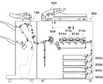
図1は、本発明の実施形態に係るシート処理装置を備える画像形成システムの概略構成を示す断面図である。この画像形成システムは、大略的に、画像形成装置300、自動原稿給紙装置500及びシート処理装置100から構成されている。
<Overall configuration of image forming system>
FIG. 1 is a cross-sectional view illustrating a schematic configuration of an image forming system including a sheet processing apparatus according to an embodiment of the present invention. This image forming system generally includes an
自動原稿給紙装置500は、原稿を1枚ずつ自動送給しながら原稿面に光を照射し、その反射光をCCDラインセンサ等の光電変換素子で読み取り、画像信号としてのアナログ信号を画像形成装置の制御部へ出力する。
The
画像形成装置300では、先ず、光電変換素子から出力されたアナログ信号がデジタル信号へ変換される。そして、得られたデジタル信号に基づいて、イエロー,マゼンタ,シアン,ブラックの感光ドラム914a,914b,914c,914dにそれぞれ、各色の静電潜像が形成される。静電潜像は、各色のトナーにより現像されてトナー像が感光ドラム914a,914b,914c,914dに形成される。一方、画像形成装置300内のカセット900a〜900dのいずれかから、画像形成(印刷)用のシートが感光ドラム914aに向けて送給され、感光ドラム914a,914b,914c,914dの順にトナー像がシートに直接転写される。トナー像が転写されたシートは定着器904に搬送され、定着器904はトナー像をシートに定着させて、シート処理装置100へ送り出す。シート処理装置100については、次に、図2を参照して詳細に説明する。
In the
<シート処理装置の概略構造>
図2は、シート処理装置100の構成を示す断面図である。ここでは、シート処理装置100は、画像形成装置300から排出されるシートを取り込むように画像形成装置300に接続されているが、シート処理装置100と画像形成装置300とは一体構造となっていてもよい。
<Schematic structure of sheet processing apparatus>
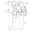
FIG. 2 is a cross-sectional view illustrating a configuration of the
シート処理装置100は、中綴じ処理装置(サドルユニット)135と、シート積載処理装置としての平綴じ処理装置とを備えている。画像形成装置300から排出されたシートはシート処理装置100の入口搬送ローラ対102に受け渡され、その際に入口センサ101によってシートの受け渡しタイミングが検知される。入口搬送ローラ対102は入口搬送モータドライバ278(後述する図6参照)及び入口搬送モータ208によって駆動される。
The
入口搬送ローラ対102により搬送されたシートは、搬送パス103及びシートに穿孔を行うためのパンチユニット250を通過後、第1のシフト搬送ローラ対105及び第2のシフト搬送ローラ対106に受け渡される。第1,第2のシフト搬送ローラ対105,106は、後述するシフト搬送モータドライバ290(後述する図6参照)及びシフト搬送モータ291によって駆動される。
The sheet conveyed by the inlet
第1,第2のシフト搬送ローラ対105,106を、予め定められた一定量だけ駆動させた後、横レジ検知センサ104によってシートの搬送方向に直交する幅方向の端部位置が検知される。得られた検知結果からシート搬送方向の中心位置からのシートの横レジずれ量が求められ、シフトユニット108によって横レジずれを補正するように、シートは、図2の紙面に垂直な方向(手前方向/奥方向)に移動される(シフト動作)。このシフト動作は、シフト搬送ローラ対105,106で搬送されている間に行われる。なお、このシフト動作(横レジ補正)は、既知の技術であるので詳細な説明は省略する。
After driving the first and second shift conveyance roller pairs 105 and 106 by a predetermined fixed amount, the lateral
その後、シートを所定量だけ搬送し、搬送を停止する。シートを停止させた状態で保持する期間が安定時間であり、安定時間の経過後、シートの搬送方向を反転させて搬送を開始し、所定量だけ搬送させて、シートの後端を斜行補正部材である後端ストッパ部材251に当接させて、シートの後端辺の斜行を補正する。このとき、必要に応じて、パンチユニット250で、シート後端部にパンチ穴を形成する穿孔処理を行うことができる。
Thereafter, the sheet is conveyed by a predetermined amount, and the conveyance is stopped. The period during which the sheet is held stopped is the stable time. After the stable time has elapsed, the conveyance direction of the sheet is reversed and the conveyance is started, and the sheet is conveyed by a predetermined amount to correct the skew of the trailing edge of the sheet. The sheet is brought into contact with the trailing
その後、シートは、搬送ローラ110、離間ローラ111及びバッファーローラ対115により搬送された後、フラッパー118の姿勢を制御することにより、上搬送路117又は束搬送路121のいずれかへ搬送される。シートは、上搬送路117へ導かれた場合、上排紙ローラ120によって上トレイ136に排紙される。一方、シートは、束搬送路121に導かれた場合、バッファーローラ対122、束搬送ローラ対124により、順次、下搬送路126内を通過する。なお、図2には、フラッパー118がシートを束搬送路121に導く状態が示されている。
Thereafter, the sheet is conveyed by the
シートを中綴じ処理する場合、フラッパー125の姿勢が制御されることで、シートはサドル搬送路133に搬送され、更にサドル入口ローラ対134により中綴じ処理装置135に導かれ、中綴じ処理装置135において中綴じ処理される。なお、中綴じ処理は一般的な処理であり、本発明の要部ではないため、その詳細な説明は省略する。
When performing saddle stitch processing on the sheet, the posture of the
シートを下トレイ137に排紙する場合、シートは、束搬送ローラ対124及びフラッパー125により下搬送路126に搬送される。そして、シートは、下排紙ローラ対128により中間処理トレイ138に排紙され、不図示のパドルとローレットベルト等の戻し手段により、中間処理トレイ138上で整合処理される。その後、必要に応じてシート束に対してステイプラ132により綴じ処理が施された後、シート束は束排紙ローラ対130により下トレイ137に排紙される。
When the sheet is discharged to the
<パンチユニット250の構成>
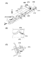
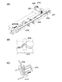
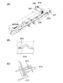
図3、図4及び図5それぞれ、シート処理装置100が有するパンチユニット250の構成と動作を示す図である。図3〜図5の各(A)は、パンチユニット250の斜視図であり、各(B)はパンチユニット250が備えるスライダ260の一部を各(A)中の矢印f方向から見た図であり、各(C)はパンチユニット250を各(A)中の矢印g方向から見た断面図である。
<Configuration of
3, 4, and 5 are diagrams showing the configuration and operation of a
第1のパンチセンサ271及び第2のパンチセンサ272は、スライダ260がどの位置に在るかを判別する。例えば、図3に示されるように、第1のパンチセンサ271及び第2のパンチセンサ272がスライダ260によって遮光されているときは、矢印g方向から見て、スライダ260は奥側に位置する。一方、図5に示されるように、第1のパンチセンサ271及び第2のパンチセンサ272が遮光されていないときは、矢印g方向から見て、スライダ260は手前側に位置する。
The
スライダ260は、パンチモータドライバ279(後に示す図6参照)によって駆動されるパンチモータ221により駆動され、図3〜5の各(A)に示される矢印P方向と矢印Q方向に動く。例えば、スライダ260は、パンチモータ221が図3に示すように時計回りに回転すると矢印Q方向に動き、図5に示すように反時計回りに回転すると矢印P方向に動く。図3の位置にあるポンチ273に固定されているピン274が、カム275をスライダ260の移動方向と垂直な方向に移動すると、図4に示されるように、ピン274と連動するポンチ273がシートに対して垂直に移動してシートに穿孔を行う。その後、更にスライダ260が移動すると、図5の状態となり、ポンチ273がシートから抜ける。
The
パンチモータ221の反出力軸に固定されたエンコーダ280は、パンチモータ221が回転したときに、パンチモータクロックセンサ276にクロックを発生させる。このクロックをカウントすることで、パンチモータ221によって動作するスライダ260の移動量が検知される。なお、スライダ260が所定距離を1回移動すると1回の穿孔動作が終了する。
The
<画像形成システムの制御ブロック>
図6は、画像形成システムの制御ブロック図である。システム制御部305は、CPU310、記憶手段としてのROM306及びRAM307を有している。ROM306には制御プログラムが格納されており、CPU310が制御プログラムをRAM307に展開し、実行することによって、画像形成システムの全体制御が実行される。すなわち、システム制御部305により、原稿給送装置制御部301、イメージリーダ制御部302、画像信号制御部303、プリンタ制御部304、操作部308及びシート処理装置制御部501が総括的に制御される。RAM307は、制御データを一時的に保持し、また、制御に伴う演算処理の作業領域として用いられる。
<Control block of image forming system>
FIG. 6 is a control block diagram of the image forming system. The
原稿給送装置制御部301は、自動原稿給紙装置500をシステム制御部305からの指示に基づいて駆動制御する。イメージリーダ制御部302は、原稿面を読み取るための光源やレンズ、撮像素子等の光学系に対する駆動制御を行い、撮像素子から出力されたRGBのアナログ画像信号を画像信号制御部303へ転送する。画像信号制御部303は、システム制御部305からの指示に従い、イメージリーダ制御部302から受信したRGBのアナログ画像信号をデジタル信号に変換し、更に各種の画像処理を施して、プリンタ制御部304に出力する。プリンタ制御部304はシートに画像を形成する。
The
操作部308は、画像形成に関する各種機能を設定する複数のキーや、設定情報を表示するための表示部等を有している。操作部308の各キーが押下されることで入力されるキー信号はシステム制御部305に供給され、システム制御部305がキー信号に従う処理を行い、この処理に関する情報が表示部に表示される。
The
シート処理装置制御部501は、シート処理装置100に搭載されており、通信用IC(不図示)を介してシステム制御部305とデータ通信を行うことによって、シート処理装置100の動作を制御する。シート処理装置制御部501は、CPU401,ROM402およびRAM403を有している。CPU401は、ROM402に格納されている制御プログラムをRAM403に展開し、実行することによって、シート処理装置100を構成しているアクチュエータやセンサ等の各種の駆動部を制御する。例えば、図2に示されている入口センサ101、入口搬送ローラ対102を駆動させる入口搬送モータ208、シフト搬送ローラ対105,106を駆動させるシフト搬送モータ291等が、シート処理装置制御部501によって制御される。RAM403は、制御データを一時的に保持し、また、制御に伴う演算処理の作業領域として用いられる。
The sheet processing
<画像形成システムにおけるシートの反転搬送制御>
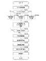
図7は、画像形成システムで実行されるシートの反転搬送制御のフローチャートである。すなわち、画像形成装置300からシート処理装置100に搬入されたシートに対する搬送、反転搬送制御による搬送方向の反転、シートの後端辺の斜行補正と穿孔処理、穿孔処理のシート搬送について説明する。ここでは、所謂、原稿の複写(コピー)を行う場合を取り上げる。図7に示した制御フローは、原則として、システム制御部305からの指示に基づいて、シート処理装置制御部501のCPU401がシート処理装置100を構成する各種の駆動部を制御することにより実現される。
<Reverse conveyance control of sheet in image forming system>
FIG. 7 is a flowchart of sheet reverse conveyance control executed in the image forming system. That is, conveyance of a sheet carried from the
最初に、原稿が自動原稿給紙装置500にセットされ、複写枚数、拡大/縮小印刷、穿孔処理の有無等の画像形成条件の設定が行われ、複写開始の指示が入力された後、原稿面が読み取られ、読み取られた原稿面の画像がシートに形成される。このとき、CPU401は、画像が形成されるシートに関するシート情報をシステム制御部305から受信する(ステップS100)。
First, a document is set on the
ここで、シートを給紙するカセットは、カセット900a〜900dの中からユーザにより指定されるか、又は、設定された画像形成条件にしたがってシステム制御部305が自動的に決定する。システム制御部305は、指定され又は決定されたカセットに収容されているシートのシート情報をシート処理装置制御部501へ送信する。ここでは、CPU401は、選択されたカセットに収容されているシートのサイズをシート情報として受信するものとする。
Here, a cassette for feeding sheets is designated by the user from among the cassettes 900a to 900d, or is automatically determined by the
CPU401は、受信したシート情報に基づいて、シートサイズを判別する(ステップS101)。そして、CPU401は、判別されたシートサイズに応じて、シートの搬送方向を反転させる反転搬送の際にシートを停止させた状態に保持する安定時間を設定する(ステップS102a,102b,102c)。 The CPU 401 determines the sheet size based on the received sheet information (step S101). Then, the CPU 401 sets a stable time for holding the sheet stopped in the reverse conveyance for reversing the sheet conveyance direction according to the determined sheet size (steps S102a, 102b, and 102c).
図8は、CPU401が安定時間を設定するために用いるテーブルの一例であり、ROM402に格納されている。シートサイズがスモールサイズ(搬送方向長さが216mm未満)である場合、安定時間Tは「5(msec)」に設定される(ステップS102a)。シートサイズがミディアムサイズ(搬送方向長さが216mm以上300mm未満)である場合、安定時間Tは「15(msec)」に設定される(ステップS102b)。シートサイズがラージサイズ(搬送方向長さが300mm以上)である場合、安定時間Tは「30(msec)」に設定される(ステップS102c)。
FIG. 8 is an example of a table used by the CPU 401 to set a stable time, and is stored in the
なお、安定時間Tの設定値は図8に示される値に限定されるものではない。また、図8の安定時間は、シートサイズ以外のシートの特性、例えば、坪量や材質等は同じであって、シートサイズのみが異なる場合について設定されている。サイズが同じであって坪量や材質等の他の特性が異なるシートに対して、図8に示したテーブルに相当する、シート特性に応じて安定時間が設定されたテーブルがROM402に格納されている構成とすることができる。CPU401は、適宜、適切な安定時間を読み出して、安定時間を設定する。 The set value of the stabilization time T is not limited to the value shown in FIG. Further, the stabilization time of FIG. 8 is set when the sheet characteristics other than the sheet size, for example, the basis weight and material are the same, but only the sheet size is different. For a sheet having the same size and different other characteristics such as basis weight and material, a table corresponding to the table shown in FIG. It can be set as a structure. The CPU 401 reads an appropriate stabilization time as appropriate and sets the stabilization time.
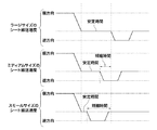
図9は、シートをスイッチバック制御する際のシートサイズと安定時間との関係を示すタイミングチャートである。図9において、「順方向」は上流側から下流側へシートを搬送すること指し、「逆方向」は、反転搬送により、順方向と反対の、下流側から上流側へシートを搬送することを指す。 FIG. 9 is a timing chart showing the relationship between the sheet size and the stabilization time when the sheet is switched back. In FIG. 9, “forward direction” refers to conveying a sheet from the upstream side to the downstream side, and “reverse direction” refers to conveying the sheet from the downstream side to the upstream side opposite to the forward direction by reverse conveyance. Point to.
シートサイズがミディアムサイズの場合の安定時間は、シートサイズがラージサイズの場合の安定時間よりも短いため、その差の時間だけ処理を速く行うことができる。同様に、シートサイズがスモールサイズの場合の安定時間は、シートサイズがミディアムサイズの場合の安定時間よりも短いため、その差の時間だけ、処理を速く行うことができ、シートサイズがラージサイズの場合よりも処理速度を更に速くすることができる。 Since the stabilization time when the sheet size is medium is shorter than the stabilization time when the sheet size is large, the processing can be performed faster by the difference time. Similarly, the stabilization time when the sheet size is small is shorter than the stabilization time when the sheet size is medium. Therefore, the processing can be performed faster by the difference time, and the sheet size is large. The processing speed can be further increased than the case.
続いて、CPU401は、入口搬送モータドライバ278やシフト搬送モータドライバ290等を制御して、入口搬送モータ208やシフト搬送モータ291等のモータ類を起動させる(ステップS103)。こうして、入口搬送ローラ対102とシフト搬送ローラ対105,106は、画像形成装置300から画像が形成されたシートを受け入れるために、シートを下流へ搬送する方向に回転を開始する。
Subsequently, the CPU 401 controls the inlet
続いて、CPU401は、入口センサ101によってシートの通過が検知された否かを判断する(ステップS104)。シートが未通過の場合(S104で“NO”)、ステップS104での待機状態となり、シートが通過すると(S104で“YES”)、処理はステップS105へ進められる。 Subsequently, the CPU 401 determines whether or not passage of the sheet is detected by the entrance sensor 101 (step S104). If the sheet has not passed (“NO” in S104), the standby state is set in step S104. If the sheet passes (“YES” in S104), the process proceeds to step S105.
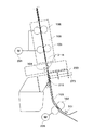
図10は、シートの先端がシート処理装置100に入ったことを入口センサ101が検知した状態を示す図である。CPU401は、シートサイズに応じて予め定められた搬送距離だけシートを搬送する(ステップS105)。この搬送距離は、シートの検出位置である入口センサ101の配設位置からシートの反転搬送を開始する位置までの距離である。図11は、反転搬送のためにシートを停止させた状態を示す図である。なお、シートサイズが大きくなれば、この搬送距離は長くなる。
FIG. 10 is a diagram illustrating a state in which the
ステップS105の後、CPU401は、ステップS102a,102b,102cのいずれかで設定された安定時間の間、シートを停止させた状態で保持する(ステップS106)。これは、シートの搬送を停止させた直後には、モータ類の固有振動、ローラやシート自体の慣性力によって振動し、負荷が大きくなっているため、これらの振動が安定するのを待つためである。ここで、ステップS105でのシートの搬送距離が長いほど、つまり、シートの搬送方向長さが長いほど、安定時間Tは長く設定されている。換言すれば、シートの搬送距離(シートの搬送方向長さ)が短くなるにしたがって安定時間は短く設定されるので、シートサイズが小さくなるほど、搬送するシートの時間間隔を短くして、単位時間当たりの生産性を向上させることができる。 After step S105, the CPU 401 holds the sheet in a stopped state for the stabilization time set in any of steps S102a, 102b, and 102c (step S106). This is because immediately after stopping the conveyance of the sheet, it vibrates due to the inherent vibrations of the motors and the inertial force of the rollers and the sheet itself, and the load is increased, so it is necessary to wait for these vibrations to stabilize. is there. Here, the longer the sheet conveyance distance in step S105, that is, the longer the sheet conveyance direction length, the longer the stabilization time T is set. In other words, the stabilization time is set shorter as the sheet conveyance distance (the length in the sheet conveyance direction) becomes shorter. Therefore, the smaller the sheet size, the shorter the time interval between sheets to be conveyed, Productivity can be improved.
ステップS106で安定時間の経過後、CPU401は、シートの搬送方向を反転させてシートを逆方向に搬送する(ステップS107)。更に、CPU401は、シートを逆方向に一定距離だけ搬送させて、シートの後端を後端ストッパ部材251に突き当て、シートを撓ませることによって、シートの後端辺の斜行を補正する(ステップS108)。図12は、シートの搬送方向を反転させて、シートの後端を後端ストッパ部材251に突き当てた状態を示す図である。図12に示される状態において、CPU401は、パンチモータドライバ279を制御してパンチモータ221を駆動させることによって、シートに穿孔処理を実行する(ステップS109)。その後、CPU401は、シートを順方向に搬送し、上トレイ136又は下トレイ137へ排紙する(エンド)。
After the stabilization time has elapsed in step S106, the CPU 401 reverses the sheet conveyance direction and conveys the sheet in the reverse direction (step S107). Further, the CPU 401 corrects the skew of the trailing edge of the sheet by conveying the sheet in the reverse direction by a certain distance, butting the trailing edge of the sheet against the trailing
<他の実施形態>
以上、本発明をその好適な実施形態に基づいて詳述してきたが、本発明はこれら特定の実施形態に限られるものではなく、この発明の要旨を逸脱しない範囲の様々な形態も本発明に含まれる。さらに、上述した各実施形態は本発明の一実施形態を示すものにすぎず、各実施形態を適宜組み合わせることも可能である。
<Other embodiments>
Although the present invention has been described in detail based on preferred embodiments thereof, the present invention is not limited to these specific embodiments, and various forms within the scope of the present invention are also included in the present invention. included. Furthermore, each embodiment mentioned above shows only one embodiment of this invention, and it is also possible to combine each embodiment suitably.
例えば、上記実施形態では、3種類のシートのサイズに場合分けし、3種類の安定時間を設定する形態について説明したが、これに限られず、場合分けをより少なく、逆により細かく行い、実験等から算出した線形性から安定時間を設定するようにしてもよい。上記実施形態では、シート情報としてシートサイズを用いたが、これに限られず、坪量や表面性状、厚さ、すき目、材質(マテリアル種)、コート/非コートの有無、剛度、トナーののり量等から選択される1以上のシート情報を用いて安定時間を判断してもよい。例えば、坪量が大きくなるほど、厚さが厚くなるほど、材質の密度が大きいほど、トナーののり量が多いほど、安定時間を長く設定する。更に、シート情報を保持している上流機器からシート情報を受信するとしたが、シート情報に代えて上流機器で求めた安定時間を受信するように構成することもできる。 For example, in the above-described embodiment, a case where three types of sheet sizes are classified and three types of stable times are set has been described. However, the present invention is not limited to this, and the number of cases is smaller and the reverse is performed more finely. The stabilization time may be set from the linearity calculated from In the above embodiment, the sheet size is used as the sheet information. However, the present invention is not limited to this, but the basis weight, surface properties, thickness, gap, material (material type), presence / absence of coated / uncoated, stiffness, toner paste The stabilization time may be determined using one or more pieces of sheet information selected from the amount or the like. For example, the stabilization time is set longer as the basis weight is increased, the thickness is increased, the density of the material is increased, and the amount of toner is increased. Further, the sheet information is received from the upstream device holding the sheet information. However, the stable time obtained by the upstream device can be received instead of the sheet information.
本発明は以下の処理を実行することによっても実現される。即ち、上述した実施形態の機能を実現するソフトウェア(プログラム)をネットワーク又は各種記憶媒体を介してシステム或いは装置に供給し、そのシステム或いは装置のコンピュータ(又はCPUやMPU等)がプログラムコードを読み出して実行する処理である。この場合、そのプログラム、及び該プログラムを記憶した記憶媒体は本発明を構成することになる。 The present invention can also be realized by executing the following processing. That is, software (program) that realizes the functions of the above-described embodiments is supplied to a system or apparatus via a network or various storage media, and a computer (or CPU, MPU, etc.) of the system or apparatus reads the program code. It is a process to be executed. In this case, the program and the storage medium storing the program constitute the present invention.
100 シート処理装置
251 後端ストッパ部材
300 画像形成装置
305 システム制御部
301 原稿給送装置制御部
302 イメージリーダ制御部
303 画像信号制御部、
304 プリンタ制御部
308 操作部
401 CPU
501 シート処理装置制御部
DESCRIPTION OF
304
501 Sheet processing apparatus control unit
Claims (7)
前記搬送手段により順方向へ搬送されているシートを停止させ、前記シートを停止させた位置で予め定められた安定時間の間、前記シートを保持させ、前記安定時間の経過後に前記シートの搬送方向を反転させて逆方向に搬送させるように前記搬送手段を制御する制御手段と、を有し、
前記制御手段は、前記シートの特性を示すシート情報に基づいて、前記シートの前記順方向への搬送を停止させて前記逆方向へ搬送する際の負荷が大きくなるにしたがって前記安定時間を長く設定することを特徴とするシート処理装置。 Conveying means for conveying the sheet;
The sheet conveyed in the forward direction by the conveying means is stopped, the sheet is held for a predetermined stabilization time at the position where the sheet is stopped, and the conveyance direction of the sheet after the stabilization time has elapsed. Control means for controlling the conveying means so as to be reversed and conveyed in the reverse direction,
The control means sets the stabilization time to be longer as the load when the forward conveyance of the sheet is stopped and the reverse conveyance is increased based on the sheet information indicating the characteristics of the sheet. A sheet processing apparatus.
前記制御手段は、前記搬送手段を制御して前記シートの搬送方向を反転させて前記シートを逆方向に搬送させて前記シートを前記斜行補正部材に突き当てることにより前記シートの後端辺の斜行を補正することを特徴とする請求項1記載のシート処理装置。 A skew correction member against which the sheet abuts in order to correct skew of the trailing edge of the sheet conveyed by the conveying means;
The control means controls the conveying means to reverse the conveying direction of the sheet, convey the sheet in the reverse direction, and abut the sheet against the skew feeding correction member to thereby adjust the trailing edge of the sheet. The sheet processing apparatus according to claim 1, wherein skew feeding is corrected.
前記制御手段は、前記シートの搬送方向長さが短くなるにしたがって前記安定時間を短く設定することを特徴とする請求項3記載のシート処理装置。 The sheet information is the size of the sheet,
The sheet processing apparatus according to claim 3, wherein the control unit sets the stabilization time to be shorter as the length of the sheet in the conveyance direction becomes shorter.
前記制御手段は、前記シートの厚さが薄くなるにしたがって前記安定時間を短く設定することを特徴とする請求項3又は4記載のシート処理装置。 The sheet information is the thickness of the sheet,
The sheet processing apparatus according to claim 3, wherein the control unit sets the stabilization time to be shorter as the thickness of the sheet becomes thinner.
前記画像形成装置と接続され、前記画像形成装置において画像形成されたシートが搬入されるシート処理装置と、を備える画像形成システムであって、
前記画像形成装置は、前記シートの特性を示すシート情報を前記シート処理装置へ送信する送信手段を有し、
前記シート処理装置は、前記シートを搬送する搬送手段と、順方向へ搬送されている前記シートを停止させ、前記シートを停止させた位置で予め定められた安定時間の間、前記シートを保持させ、前記安定時間の経過後に前記シートの搬送方向を反転させて逆方向に搬送させるように前記搬送手段を制御する制御手段と、を有し、
前記制御手段は、前記シートの特性を示すシート情報に基づいて、前記シートの前記順方向への搬送を停止させて前記逆方向へ搬送する際の負荷が大きくなるにしたがって前記安定時間を長く設定することを特徴とする画像形成システム。 An image forming apparatus for forming an image on a sheet;
A sheet processing apparatus connected to the image forming apparatus and into which a sheet image-formed in the image forming apparatus is carried,
The image forming apparatus includes a transmission unit that transmits sheet information indicating the characteristics of the sheet to the sheet processing apparatus,
The sheet processing apparatus stops the sheet being conveyed in a forward direction with a conveying unit that conveys the sheet, and holds the sheet for a predetermined stabilization time at a position where the sheet is stopped. Control means for controlling the conveying means so as to reverse the conveying direction of the sheet after the stable time has elapsed and to convey the sheet in the reverse direction,
The control means sets the stabilization time to be longer as the load when the forward conveyance of the sheet is stopped and the reverse conveyance is increased based on the sheet information indicating the characteristics of the sheet. An image forming system.
Priority Applications (1)
| Application Number | Priority Date | Filing Date | Title |
|---|---|---|---|
| JP2010279275A JP2012128167A (en) | 2010-12-15 | 2010-12-15 | Sheet processing device and image forming system |
Applications Claiming Priority (1)
| Application Number | Priority Date | Filing Date | Title |
|---|---|---|---|
| JP2010279275A JP2012128167A (en) | 2010-12-15 | 2010-12-15 | Sheet processing device and image forming system |
Publications (2)
| Publication Number | Publication Date |
|---|---|
| JP2012128167A true JP2012128167A (en) | 2012-07-05 |
| JP2012128167A5 JP2012128167A5 (en) | 2014-02-06 |
Family
ID=46645264
Family Applications (1)
| Application Number | Title | Priority Date | Filing Date |
|---|---|---|---|
| JP2010279275A Pending JP2012128167A (en) | 2010-12-15 | 2010-12-15 | Sheet processing device and image forming system |
Country Status (1)
| Country | Link |
|---|---|
| JP (1) | JP2012128167A (en) |
Cited By (1)
| Publication number | Priority date | Publication date | Assignee | Title |
|---|---|---|---|---|
| JP2023006116A (en) * | 2021-06-30 | 2023-01-18 | ブラザー工業株式会社 | Sheet carrier device and image formation device |
Citations (2)
| Publication number | Priority date | Publication date | Assignee | Title |
|---|---|---|---|---|
| JP2005189372A (en) * | 2003-12-25 | 2005-07-14 | Kyocera Mita Corp | Image forming apparatus |
| JP2007001757A (en) * | 2005-06-27 | 2007-01-11 | Ricoh Co Ltd | Sheet medium punching mechanism, sheet medium punching apparatus, post-processing apparatus, image forming apparatus |
-
2010
- 2010-12-15 JP JP2010279275A patent/JP2012128167A/en active Pending
Patent Citations (2)
| Publication number | Priority date | Publication date | Assignee | Title |
|---|---|---|---|---|
| JP2005189372A (en) * | 2003-12-25 | 2005-07-14 | Kyocera Mita Corp | Image forming apparatus |
| JP2007001757A (en) * | 2005-06-27 | 2007-01-11 | Ricoh Co Ltd | Sheet medium punching mechanism, sheet medium punching apparatus, post-processing apparatus, image forming apparatus |
Cited By (2)
| Publication number | Priority date | Publication date | Assignee | Title |
|---|---|---|---|---|
| JP2023006116A (en) * | 2021-06-30 | 2023-01-18 | ブラザー工業株式会社 | Sheet carrier device and image formation device |
| JP7707691B2 (en) | 2021-06-30 | 2025-07-15 | ブラザー工業株式会社 | SHEET CONVEYING DEVICE AND IMAGE FORMING APPARATUS |
Similar Documents
| Publication | Publication Date | Title |
|---|---|---|
| JP5528088B2 (en) | Sheet processing apparatus and image forming apparatus | |
| US20130032988A1 (en) | Sheet stacking apparatus | |
| JP3926639B2 (en) | Paper reversing method, paper reversing device, and image forming apparatus | |
| JP2006160518A (en) | Paper punching device, paper post-processing device including the same, and image forming apparatus | |
| JP6019847B2 (en) | Image forming system and paper conveying method | |
| US20090230619A1 (en) | Sheet processing apparatus and image forming apparatus | |
| JP2014061994A (en) | Sheet processing device and image formation device | |
| JP6000718B2 (en) | Sheet processing apparatus and image forming apparatus | |
| JP5595116B2 (en) | Sheet processing apparatus and image forming apparatus | |
| JP2009053519A (en) | Image forming system, image forming apparatus, and post processor | |
| JP4827646B2 (en) | Sheet stacking apparatus, sheet processing apparatus, and image forming apparatus including the same | |
| JP4827690B2 (en) | Sheet processing apparatus and image forming apparatus | |
| JP2012128167A (en) | Sheet processing device and image forming system | |
| JP2008105316A (en) | Bookbinding apparatus and image forming apparatus provided with bookbinding apparatus | |
| JP2005206338A (en) | Image forming device | |
| JP4944929B2 (en) | Post-processing apparatus and post-processing system | |
| US20070017397A1 (en) | Image printing system, image printing method, and image printing program | |
| US7603074B2 (en) | Image forming system, image forming device and bookbinding device | |
| JP5577867B2 (en) | Sheet folding apparatus, image forming system, and sheet folding method | |
| JP4533280B2 (en) | Sheet processing device | |
| JP2010143698A (en) | Paper postprocessing device | |
| JP2007069993A (en) | Sheet processing apparatus and image forming apparatus | |
| JP4722643B2 (en) | Sheet processing apparatus and image forming apparatus | |
| JP7331359B2 (en) | IMAGE FORMING APPARATUS AND PAPER POSITION CORRECTION METHOD | |
| JP4467486B2 (en) | Sheet processing apparatus and image forming apparatus |
Legal Events
| Date | Code | Title | Description |
|---|---|---|---|
| A521 | Written amendment |
Free format text: JAPANESE INTERMEDIATE CODE: A523 Effective date: 20131213 |
|
| A621 | Written request for application examination |
Free format text: JAPANESE INTERMEDIATE CODE: A621 Effective date: 20131213 |
|
| A977 | Report on retrieval |
Free format text: JAPANESE INTERMEDIATE CODE: A971007 Effective date: 20140704 |
|
| A131 | Notification of reasons for refusal |
Free format text: JAPANESE INTERMEDIATE CODE: A131 Effective date: 20140708 |
|
| A02 | Decision of refusal |
Free format text: JAPANESE INTERMEDIATE CODE: A02 Effective date: 20141104 |