JP2012128228A - Image forming apparatus - Google Patents
Image forming apparatus Download PDFInfo
- Publication number
- JP2012128228A JP2012128228A JP2010280197A JP2010280197A JP2012128228A JP 2012128228 A JP2012128228 A JP 2012128228A JP 2010280197 A JP2010280197 A JP 2010280197A JP 2010280197 A JP2010280197 A JP 2010280197A JP 2012128228 A JP2012128228 A JP 2012128228A
- Authority
- JP
- Japan
- Prior art keywords
- recording material
- transfer belt
- belt member
- roller
- separation
- Prior art date
- Legal status (The legal status is an assumption and is not a legal conclusion. Google has not performed a legal analysis and makes no representation as to the accuracy of the status listed.)
- Granted
Links
Images





Classifications
-
- G—PHYSICS
- G03—PHOTOGRAPHY; CINEMATOGRAPHY; ANALOGOUS TECHNIQUES USING WAVES OTHER THAN OPTICAL WAVES; ELECTROGRAPHY; HOLOGRAPHY
- G03G—ELECTROGRAPHY; ELECTROPHOTOGRAPHY; MAGNETOGRAPHY
- G03G15/00—Apparatus for electrographic processes using a charge pattern
- G03G15/65—Apparatus which relate to the handling of copy material
- G03G15/6555—Handling of sheet copy material taking place in a specific part of the copy material feeding path
- G03G15/657—Feeding path after the transfer point and up to the fixing point, e.g. guides and feeding means for handling copy material carrying an unfused toner image
-
- G—PHYSICS
- G03—PHOTOGRAPHY; CINEMATOGRAPHY; ANALOGOUS TECHNIQUES USING WAVES OTHER THAN OPTICAL WAVES; ELECTROGRAPHY; HOLOGRAPHY
- G03G—ELECTROGRAPHY; ELECTROPHOTOGRAPHY; MAGNETOGRAPHY
- G03G15/00—Apparatus for electrographic processes using a charge pattern
- G03G15/65—Apparatus which relate to the handling of copy material
- G03G15/6588—Apparatus which relate to the handling of copy material characterised by the copy material, e.g. postcards, large copies, multi-layered materials, coloured sheet material
- G03G15/6594—Apparatus which relate to the handling of copy material characterised by the copy material, e.g. postcards, large copies, multi-layered materials, coloured sheet material characterised by the format or the thickness, e.g. endless forms
-
- G—PHYSICS
- G03—PHOTOGRAPHY; CINEMATOGRAPHY; ANALOGOUS TECHNIQUES USING WAVES OTHER THAN OPTICAL WAVES; ELECTROGRAPHY; HOLOGRAPHY
- G03G—ELECTROGRAPHY; ELECTROPHOTOGRAPHY; MAGNETOGRAPHY
- G03G2215/00—Apparatus for electrophotographic processes
- G03G2215/01—Apparatus for electrophotographic processes for producing multicoloured copies
- G03G2215/0103—Plural electrographic recording members
- G03G2215/0119—Linear arrangement adjacent plural transfer points
- G03G2215/0122—Linear arrangement adjacent plural transfer points primary transfer to an intermediate transfer belt
- G03G2215/0125—Linear arrangement adjacent plural transfer points primary transfer to an intermediate transfer belt the linear arrangement being horizontal or slanted
- G03G2215/0129—Linear arrangement adjacent plural transfer points primary transfer to an intermediate transfer belt the linear arrangement being horizontal or slanted horizontal medium transport path at the secondary transfer
Landscapes
- Physics & Mathematics (AREA)
- General Physics & Mathematics (AREA)
- Electrostatic Charge, Transfer And Separation In Electrography (AREA)
- Paper Feeding For Electrophotography (AREA)
- Separation, Sorting, Adjustment, Or Bending Of Sheets To Be Conveyed (AREA)
Abstract
【課題】停止モードが割り込み実行されてベルト部材の回転が停止される際に、案内部材周りで新たな記録材ジャムが発生しないで済む画像形成装置を提供する。分離補助装置の作動を伴ってベルト部材を緊急停止させた際に、ベルト部材に変形を残さないで済む画像形成装置を提供する。
【解決手段】給紙部で記録材のジャムが発生すると、画像形成を中断して二次転写部N1のニップ圧力を解除した後に転写ベルト24を緊急停止させる。そのとき、先端コロ41によって転写ベルト24を押し上げて転写ベルト24から記録材Pを分離させた後に、先端コロ41による転写ベルト24の押し上げを解除し、その後、記録材Pの先端を分離爪29に保持させた状態で転写ベルト24を停止させる。
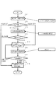
【選択図】図1Provided is an image forming apparatus in which a new recording material jam does not occur around a guide member when a stop mode is interrupted and rotation of a belt member is stopped. Provided is an image forming apparatus that does not leave a deformation in a belt member when the belt member is brought to an emergency stop with an operation of a separation assisting device.
When a recording material jam occurs in a paper feeding unit, image formation is interrupted and the nip pressure of the secondary transfer unit N1 is released, and then the transfer belt 24 is urgently stopped. At this time, after the transfer belt 24 is pushed up by the leading end roller 41 to separate the recording material P from the transfer belt 24, the pushing up of the transfer belt 24 by the leading end roller 41 is released, and then the leading end of the recording material P is separated from the separation claw 29. In this state, the transfer belt 24 is stopped.
[Selection] Figure 1
Description
本発明は、像担持体からベルト部材に担持された記録材へトナー像を転写する画像形成装置、詳しくは記録材ジャム発生に伴う緊急停止時にベルト部材周りで二次的な記録材ジャムを発生させないための制御に関する。 The present invention relates to an image forming apparatus for transferring a toner image from an image carrier to a recording material carried on a belt member. More specifically, a secondary recording material jam is generated around the belt member during an emergency stop accompanying the occurrence of the recording material jam. It relates to control not to let it.
分離ローラを含む複数のローラに張架された転写ベルトにより記録材を担持搬送する電子写真方式の画像形成装置では、転写ベルト上の記録材は、転写部を通過すると転写ベルトに静電的に吸着される。 In an electrophotographic image forming apparatus in which a recording material is carried and conveyed by a transfer belt stretched around a plurality of rollers including a separation roller, the recording material on the transfer belt is electrostatically applied to the transfer belt when passing the transfer portion. Adsorbed.
しかし、記録材の剛度が低いと、転写ベルトを張架する分離ローラの曲率と記録材の剛度を利用するだけでは、記録材を転写ベルトから十分に分離することができない。すなわち、記録材が分離ローラの位置で転写ベルトに張り付いたままとなり、分離不良が生ずる場合がある。そこで、転写ベルトを張架する分離ローラ表面に一様に突起物を形成しておき、分離位置において突起物により転写ベルトにうねりをつけて、記録材を分離させる方法が提案されている(特許文献1)。 However, if the recording material has low rigidity, the recording material cannot be sufficiently separated from the transfer belt only by using the curvature of the separation roller that stretches the transfer belt and the rigidity of the recording material. That is, the recording material may remain stuck to the transfer belt at the position of the separation roller, and separation failure may occur. Therefore, a method has been proposed in which protrusions are uniformly formed on the surface of the separation roller on which the transfer belt is stretched, and the recording material is separated by corrugating the transfer belt with the protrusions at the separation position (patent). Reference 1).
分離ローラ表面に恒常的な突起物を設ける構成によって、分離位置において転写ベルトにうねりを形成することができるが、転写ベルトには、常に局所的に大きな張力を働かせてしまう。その結果、転写ベルトの局所的な磨耗が生じることによって、転写部を通過する際の抵抗ムラが発生する。転写ベルトに局所的に大きな張力が作用して恒常的な突起物による変形が生じた場合、転写部を通過する際に接触ムラ、抵抗ムラを生じる可能性がある。恒常的な突起物に頼る方法では、これらの影響でトナー像の転写性が安定しなくなり、転写ムラが発生する可能性もある。 By providing a permanent protrusion on the surface of the separation roller, undulation can be formed on the transfer belt at the separation position, but a large tension is always applied locally to the transfer belt. As a result, local abrasion of the transfer belt occurs, resulting in uneven resistance when passing through the transfer portion. When large tension acts locally on the transfer belt and deformation due to permanent protrusions occurs, contact unevenness and resistance unevenness may occur when passing through the transfer portion. In the method that relies on a constant protrusion, the transferability of the toner image becomes unstable due to these effects, and transfer unevenness may occur.
また、記録材を担持する円筒状の記録材担持シートを、記録材分離のために変形させつつも、変形による磨耗を低減する方法が特許文献2に記載されている。特許文献2には、円筒状の記録材担持シートの内側に、記録材担持面の押し上げ手段としてコロを設けた構成が記載されている。押し上げ手段としてのコロは、転写シートを押し上げる位置と押し上げない位置との間で移動するように構成されている。円筒状の記録材担持シートを内側からコロで押し上げることによって、記録材担持シートから記録材を分離させるが、分離させない間は、コロによって記録材担持シートを押し上げないように制御している。
特許文献2に示される構成を転写ベルトに適用すると、転写ベルト上の記録材に像担持体上のトナー像を転写する転写部から記録材搬送方向において下流側に、分離工程時に転写ベルトを局所的に押し上げる押し上げ手段を配置する構成になる。
When the configuration shown in
薄い紙等の剛度が弱い記録材の場合には、転写ベルトを押し上げ手段によって局所的に押し上げた状態で記録材を搬送させる。これにより、記録材にうねりをつけて、分離工程時の記録材のこしの強さを一時的に大きくすることができる(図6参照)。 In the case of a recording material with low rigidity such as thin paper, the recording material is conveyed in a state where the transfer belt is locally pushed up by the pushing-up means. As a result, the recording material can be undulated and the strength of the recording material can be temporarily increased during the separation process (see FIG. 6).
しかし、転写ベルト等のベルト部材を用いる画像形成装置において、画像形成時に記録材ジャムが発生すると、停止モードが割り込み実行されてベルト部材の回転が停止される。このとき、停止したベルト部材に張り付いた記録材がトナー像の転写部やその上流側に残っていると、その後のジャム処理において、ベルト部材から記録材を除去することが困難である。 However, in an image forming apparatus using a belt member such as a transfer belt, when a recording material jam occurs during image formation, the stop mode is interrupted and rotation of the belt member is stopped. At this time, if the recording material stuck to the stopped belt member remains on the toner image transfer portion or upstream thereof, it is difficult to remove the recording material from the belt member in the subsequent jam processing.
そのため、記録材をベルト部材から分離した位置に移動させるために、ジャム後にベルト部材を所定期間回転させる構成が挙げられる。しかし、薄い紙の場合には、ベルト部材から分離されずに、巻き付くおそれがある。 Therefore, in order to move the recording material to a position separated from the belt member, there is a configuration in which the belt member is rotated for a predetermined period after the jam. However, in the case of thin paper, there is a risk that the paper will wind without being separated from the belt member.
本発明は、停止モードが割り込み実行された場合にも、その回転期間中に押し上げ手段を動作させて、ベルト部材から記録材を確実に分離させて巻き付きを回避できる画像形成装置を提供することを目的としている。 An object of the present invention is to provide an image forming apparatus capable of avoiding wrapping by operating a push-up means during a rotation period to reliably separate a recording material from a belt member even when a stop mode is interrupted. It is aimed.
本発明の画像形成装置は、像担持体と、張架された回転可能なベルト部材と、前記ベルト部材に担持搬送される記録材に前記像担持体に形成されたトナー像を転写する転写部を形成する転写手段と、前記ベルト部材を張架し、前記ベルト部材に担持された記録材を前記ベルト部材から分離可能である分離ローラとを有するものである。そして、前記ベルト部材に担持されている記録材を前記ベルト部材から分離するために、前記ベルト部材の回転方向において前記分離ローラよりも上流側で前記転写部より下流側のベルト面を前記ベルト部材の幅方向において局所的に押し上げ可能である押し上げ手段と、画像形成動作中に異常が生じたときには、画像形成動作を停止した後に、前記押し上げ手段を押し上げた状態でベルト部材を回転させてからベルト部材の回転を停止する停止モードを実行する実行部とを有する。 An image forming apparatus according to the present invention includes an image carrier, a rotatable belt member that is stretched, and a transfer unit that transfers a toner image formed on the image carrier to a recording material carried and conveyed by the belt member. And a separation roller that stretches the belt member and can separate the recording material carried on the belt member from the belt member. In order to separate the recording material carried on the belt member from the belt member, a belt surface upstream of the separation roller and downstream of the transfer portion in the rotation direction of the belt member is disposed on the belt member. And a push-up means that can be pushed up locally in the width direction, and when an abnormality occurs during the image forming operation, after stopping the image forming operation, the belt member is rotated while the push-up means is pushed up, and then the belt And an execution unit that executes a stop mode for stopping the rotation of the member.
本発明の画像形成装置では、停止モード時にベルト部材上にベルト部材から分離しにくい記録材が残留しても、この記録材をベルト部材から除去する安定性を高めることができる。 In the image forming apparatus of the present invention, even when a recording material that is difficult to separate from the belt member remains on the belt member in the stop mode, the stability of removing the recording material from the belt member can be improved.
以下、図面を参照して本発明の実施形態を詳細に説明する。本発明は、記録材ジャム発生時に転写ベルトの幅方向の複数位置を内側面から外側へ突き出して記録材にリブを形成する限りにおいて、実施形態の構成の一部または全部を、その代替的な構成で置き換えた別の実施形態でも実施できる。 Hereinafter, embodiments of the present invention will be described in detail with reference to the drawings. In the present invention, as long as a recording material jam occurs and a plurality of positions in the width direction of the transfer belt protrude from the inner surface to the outside and ribs are formed on the recording material, a part or all of the configuration of the embodiment can be used as an alternative. Another embodiment in which the configuration is replaced can also be implemented.
従って、転写ベルトに担持させた記録材にトナー像を転写する画像形成装置であれば、トナー像形成部の構成とは無関係に実施できる。モノクロ/フルカラー、一成分現像剤/二成分現像剤、タンデム型/1ドラム型、中間転写型/直接転写型の区別無く実施できる。 Therefore, any image forming apparatus that transfers a toner image onto a recording material carried on a transfer belt can be implemented regardless of the configuration of the toner image forming unit. It can be carried out without distinction between monochrome / full color, one-component developer / two-component developer, tandem type / 1 drum type, intermediate transfer type / direct transfer type.
本実施形態では、トナー像の形成/転写に係る主要部のみを説明するが、本発明は、必要な機器、装備、筐体構造を加えて、プリンタ、各種印刷機、複写機、FAX、複合機等、種々の用途の画像形成装置で実施できる。 In the present embodiment, only main parts related to toner image formation / transfer will be described. However, the present invention includes a printer, various printing machines, a copier, a fax machine, a composite machine, in addition to necessary equipment, equipment, and a housing structure. The image forming apparatus can be used for various purposes such as a printer.
なお、特許文献1、2に示される画像形成装置の一般的な事項については、図示を省略して重複する説明を省略する。
In addition, about the general matter of the image forming apparatus shown by
<画像形成装置>
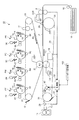
図1は画像形成装置の構成の説明図である。図2は転写ベルトの分離部で発生する記録材ジャムの説明図である。
<Image forming apparatus>
FIG. 1 is an explanatory diagram of the configuration of the image forming apparatus. FIG. 2 is an explanatory diagram of a recording material jam that occurs at the separation portion of the transfer belt.
図1に示すように、画像形成装置10は、中間転写ベルト6に沿ってイエロー、マゼンタ、シアン、ブラックの画像形成部PY、PM、PC、PKを配列したタンデム型中間転写方式のフルカラープリンタである。
As shown in FIG. 1, the
画像形成部PYでは、感光ドラム1Yにイエロートナー像が形成されて中間転写ベルト6に一次転写される。画像形成部PMでは、感光ドラム1Mにマゼンタトナー像が形成されて中間転写ベルト6に一次転写される。画像形成部PC、PKでは、それぞれ感光ドラム1C、1Kにシアントナー像、ブラックトナー像が形成されて中間転写ベルト6上に順次一次転写される。
In the image forming unit PY, a yellow toner image is formed on the
記録材Pは、記録材カセット15から引き出され、分離ローラ16によって1枚ずつに分離される。レジストローラ8は、記録材Pを一旦停止し、中間転写ベルト6上のトナー像が二次転写部N1に搬送されてくるのに同期して転写ベルト24に記録材Pを供給する。記録材Pは、吸着ローラ28に帯電されて転写ベルト24に密着し、転写ベルト24に担持されて二次転写部N1へ搬送される。
The recording material P is pulled out from the
中間転写ベルト6に担持された四色のトナー像は、二次転写部N1へ搬送され、転写ベルト24上の記録材Pに重ねて二次転写部N1を挟持搬送される。その過程で、二次転写ローラ9に電圧が印加されることで、中間転写ベルト6から記録材Pへ二次転写される。転写されずに中間転写ベルト6に残った転写残トナーは、ベルトクリーニング装置12によって回収される。
The four color toner images carried on the intermediate transfer belt 6 are transported to the secondary transfer portion N1, and the secondary transfer portion N1 is nipped and transported over the recording material P on the
未定着トナー像が載った記録材Pは、分離ローラ26位置で、転写ベルト24から分離される。四色のトナー像を二次転写された記録材Pは、転写ベルト24に搬送され、分離ローラ26の湾曲面で転写ベルト24から曲率分離して定着装置13へ送り込まれ、加熱加圧を受けてトナー像を定着された後に機体外へ排出される。
The recording material P on which the unfixed toner image is placed is separated from the
画像形成部PY、PM、PC、PKは、現像装置4Y、4M、4C、4Kで用いるトナーの色がイエロー、マゼンタ、シアン、ブラックと異なる以外は、実質的に同一に構成される。以下では、イエローの画像形成部PYについて説明し、他の画像形成部PM、PC、PKについては、説明中の構成部材に付した符号の末尾のYをM、C、Kに読み替えて説明されるものとする。
The image forming units PY, PM, PC, and PK are configured substantially the same except that the color of toner used in the developing
画像形成部PYは、感光ドラム1Yの周囲に、コロナ帯電器2Y、露光装置3Y、現像装置4Y、一次転写ローラ5Y、ドラムクリーニング装置11Yを配置している。
In the image forming unit PY, a corona charger 2Y, an
感光ドラム1Yは、250〜300mm/secのプロセススピードで矢印R1方向に回転する。コロナ帯電器2Yは、感光ドラム1Yの表面を帯電させる。露光装置3Yは、イエローの分解色画像を展開した走査線画像データをON−OFF変調したレーザービームを走査して、感光ドラム1Yに画像の静電像を書き込む。現像装置4Yは、トナーとキャリアを含む二成分現像剤を用いて静電像を反転現像することにより、感光ドラム1Yにトナー像を形成する。
The
一次転写ローラ5Yは、中間転写ベルト6の内側面に当接して、感光ドラム1Yと中間転写ベルト6の間に一次転写部TYを形成する。一次転写ローラ5Yに電圧を印加することで、感光ドラム1Yに担持されたトナー像が中間転写ベルト6へ一次転写される。ドラムクリーニング装置11Yは、感光ドラム1Yにクリーニングブレードを摺擦させて転写残トナーを回収する。
The
ところで、近年は、画像形成装置の用途拡大に伴って、薄紙等、剛性(剛度)の低い記録材への対応が求められている。しかし、剛度の低い記録材は、先端がカールし易く、ガイドとの摺擦によって先端が変形して遅れ易く、安定してトナー像を転写できない。そこで、画像形成装置10では、転写ベルト24に記録材を静電的に吸着させて転写部N1を通過させている。
Incidentally, in recent years, with the expansion of applications of image forming apparatuses, it has been demanded to cope with recording materials having low rigidity (rigidity) such as thin paper. However, a recording material with low rigidity tends to curl the tip, and the tip tends to be deformed and delayed by rubbing with the guide, and the toner image cannot be transferred stably. Therefore, in the
しかし、画像形成装置10では、坪量が40g/m2以下という剛度が極端に低い記録材への対応を図っている。記録材の剛度が極端に低いと、分離爪29だけでは、転写ベルト24からの分離が困難になる。
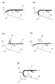
However, the
図2の(a)に示すように、記録材Pの剛度が高い場合は、転写ベルト24に吸着された記録材Pが分離ローラ26に差し掛かると先端が曲率分離するため、記録材を分離爪29に引っ掛けて分離を補助できる。
As shown in FIG. 2A, when the recording material P has high rigidity, when the recording material P attracted to the
図2の(b)に示すように、記録材Pの剛度が低い場合は、分離ローラ26に差し掛かっても記録材Pの先端が曲率分離しないため、記録材が転写ベルト24に貼りついたままとなり、分離爪29では分離を補助できない。この現象は、記録材Pが乾燥して水分量が小さいため、記録材Pの抵抗が大きく、記録材Pと転写ベルト24との間の電気的な吸着力が大きくなる低温低湿環境で顕著に起こる。
As shown in FIG. 2B, when the recording material P has low rigidity, the recording material P remains attached to the
図2の(c)に示すように、転写ベルト24から記録材Pを分離補助する手法として、転写ベルト24に吸着された記録材から電荷を除去して、電気的な吸着力を低減する方法がある。トナー像が転写された記録材Pの表面にコロナ除電器35を設けている。転写ベルト24と記録材Pの吸着力を低減させることで、剛度が低い記録材Pでも、分離ローラ26の曲率部で記録材Pの先端を分離できる。また、この状態になれば分離爪29の効果も期待できるため、図2の(d)に示すように、分離爪29にコロナ除電器35を組み合わせることで、転写ベルト24からの分離を確実に行うことが可能になる。
As shown in FIG. 2 (c), as a method for assisting in separating the recording material P from the
しかし、コロナ除電器35が発生するオゾンは転写ベルト24のゴム材料に悪影響を及ぼして寿命を低下させる。また、コロナ除電器35やその電源は、画像形成装置の製造コストの削減や小型化を妨げる。コロナ除電器35に頼って転写ベルト24の電荷を除去する手法は、記録材の抵抗が高く除電しにくい低湿環境下では効果が低く、分離不良を招きやすい問題もある。
However, the ozone generated by the corona
そのため、記録材Pの転写、搬送を行う転写ベルト24を有する画像形成装置10では、コロナ除電器に頼ることなく、剛度の低い記録材Pを転写ベルト24によって安定して搬送・分離を行う必要がある。転写ベルト24からの分離を補助する技術として、記録材Pに搬送方向と直角な方向のうねり与えて、搬送方向の剛度を高くする技術を採用しないと、40g/m2以下の記録材Pは転写ベルト24からの分離が困難である。
Therefore, in the
<中間転写ベルト>
図3は二次転写部の解除構造の説明図である。図1に示すように、中間転写ベルト6は、テンションローラ22、ベルト駆動ローラ20、及び二次転写対向ローラ21に張架されて矢印R2方向へ上記のプロセススピードで回転する。
<Intermediate transfer belt>
FIG. 3 is an explanatory diagram of the release structure of the secondary transfer portion. As shown in FIG. 1, the intermediate transfer belt 6 is stretched around a
中間転写ベルト6は、ポリイミド、ポリカーボネートなどの樹脂または各種ゴム等に帯電防止剤としてのカーボンブラックを適当量含有させて体積抵抗率を1×10⁹〜1×10¹⁴[Ω・cm]に調整してある。中間転写ベルト6は、厚みを0.07〜0.1[mm]としている。 The intermediate transfer belt 6 has a volume resistivity adjusted to 1 × 10 9 to 1 × 10 14 [Ω · cm] by containing an appropriate amount of carbon black as an antistatic agent in resins such as polyimide and polycarbonate, or various rubbers. It is. The intermediate transfer belt 6 has a thickness of 0.07 to 0.1 [mm].
二次転写ローラ9は、ステンレス製の芯金の周囲にイオン導電系発泡ゴム(NBRゴム)の弾性層を形成した外径が24mm、抵抗値が1×10⁵〜1×10⁷Ωのスポンジローラである。ローラ表面粗さは、Rz=6.0〜12.0(μm)である。抵抗値は、23℃、50%RHのN/N環境で2kVを印加して測定した。二次転写ローラ9に出力可変の転写電源D9が接続されている。
The
二次転写対向ローラ21によって内側面を支持された中間転写ベルト6と、二次転写ローラ9によって内側面を支持された転写ベルト24との間に転写部N1が形成される。転写ベルト24が矢印R3方向に移動することで、転写ベルト24上の記録材Pが二次転写部N1を通過する。二次転写部N1に導入された記録材Pは、ニ次転写部N1で挾持搬送され、その過程で、二次転写ローラ9には、転写電源D9から所定の値に制御されたトナーと逆極性の定電圧(転写バイアス)が印加される。転写電源D9は、二次転写電流+30〜60μAを二次転写ローラ9に印加して、中間転写ベルト6上に重ね合わされた4色のトナー像を記録材Pへ移転させる。記録材Pの乾燥状態、環境、転写するトナーの量等の要因によって必要な二次転写電流が変化する。
A transfer portion N1 is formed between the intermediate transfer belt 6 whose inner surface is supported by the secondary
図3の(b)に示すように、ニ次転写ローラ9は、昇降装置14により下降して転写ベルト24の内側面から離間可能である。転写ベルト24は、実際には、ニ次転写ローラ9によって上方へ押し上げられた状態で中間転写ベルト6に当接しているため、ニ次転写ローラ9が下降すると、転写ベルト24が中間転写ベルト6から離間して二次転写部N1が解除される。画像形成中、中間転写ベルト6から記録材Pへトナー像が二次転写される間は、図3の(a)に示すように、二次転写ローラ9が上昇して二次転写部N1を形成する。しかし、それ以外のタイミングでは、図3の(b)に示すように、二次転写ローラ9が下降してニ次転写部N1を解除している。
As shown in FIG. 3B, the
ニ次転写部N1を通過した記録材Pは、分離ローラ26まで搬送されて、分離爪29によって、転写ベルト24から分離される。ニ次転写後の中間転写ベルト6は、ベルトクリーニング装置12によって転写残トナーや紙粉等がクリーニングされる。記録材Pの分離後の転写ベルト24は、転写ベルトクリーニング装置31で、転写残トナーや紙粉等がクリーニングされる。
The recording material P that has passed through the secondary transfer portion N1 is conveyed to the
<転写ベルト>
転写ベルト24は、テンションローラを兼ねた入口ローラ25、駆動ローラを兼ねた分離ローラ26、及び二次転写対向ローラ21に張架されて、上記のプロセススピードで矢印R3方向に回転する。入口ローラ25は、両端を不図示のばね部材で支持されてベルト部材に所定の張力を発生させる。
<Transfer belt>
The
分離ローラ26は、転写ベルト24に湾曲面(分離部)を形成して表面から記録材Pを分離させる。分離ローラ26は、ステンレス製で外径が16mmのローラとなっている。
The
転写ベルト24は、引っ張り試験法(JIS K 6301)で測定したヤング率の値が10MPa以下となるような弾性体のものを使用している。転写ベルト24は、ヤング率を0.5MPa以上の材料を使用することで、ベルト形状を十分に保って回転駆動ができる。転写ベルト24は、10MPa以下の十分に弾性変形が可能な部材を使用することで、後述する分離補助装置40によって記録材Pに効果的にうねり発生させることができる。これにより、効果的な転写ベルト24からの記録材Pの分離を達成することが可能になる。転写ベルト24が、十分に弾性変形が可能であれば、図3の(a)に示すように、先端コロ41を引っ込めたときの転写ベルト24の緩和現象も起こり易いため、分離補助装置40による転写ベルト24の寿命低下も防ぐことが可能になる。
The
画像のトナー像の間隔に形成するトナーの濃度や位置情報を検知するためのトナー像による転写ベルト24の汚れを除去するために、転写ベルトクリーニング装置31を分離ローラ26に当接する位置に設けている。分離ローラ26に当接させることで、クリーニング用の余分なスペースを取らなくても済むようにしている。転写ベルトクリーニング装置31は、カウンターブレード方式のクリーニング装置である。
A transfer
<吸着部>
図1に示すように、レジストローラ8で搬送された記録材Pは、入口ローラ25に内側面を支持された転写ベルト24と直流電圧が印加された吸着ローラ28とで狭持搬送されることで転写ベルト24に吸着される。吸着ローラ28は、接地電位に接続された入口ローラ25に支持された転写ベルト24との間に吸着部N2を形成している。吸着電源D28は、吸着部N2によって記録材Pが狭持搬送される過程で、−15〜−30μAに定電流制御された吸着電圧を吸着ローラ28に印加する。
<Adsorption part>
As shown in FIG. 1, the recording material P conveyed by the
入口ローラ25は、ステンレス製の芯金の周囲にイオン導電系ソリッドゴム(NBRゴム)の弾性層を形成した外径が18mm、抵抗値が1×10⁵〜1×10⁶Ωのゴムローラである。抵抗値は、気温23℃、湿度50%RHのN/N環境で50Vを印加して測定した。
The
吸着ローラ28は、直径8mmの芯金の周囲に毛長5mmの導電性ナイロンの毛体を設けた外径18mm、抵抗値が1×10⁵〜1×10⁶Ωのファーブラシローラである。ファーブラシの毛体は、転写ベルト24に1.5〜2mm侵入している。抵抗値は、23℃、50%RHのN/N環境で100Vを印加して測定した。
The
<分離補助装置>
図4は分離補助装置の構成と動作の説明図である。図5は先端コロの配置の斜視図である。図6は分離補助装置による記録材の分離の説明図である。
<Separation assist device>
FIG. 4 is an explanatory diagram of the configuration and operation of the separation assisting device. FIG. 5 is a perspective view of the arrangement of the tip rollers. FIG. 6 is an explanatory diagram of the separation of the recording material by the separation assisting device.
図1に示すように、張架された回転可能なベルト部材の一例である転写ベルト24は、記録材Pを担持搬送して転写部の一例である二次転写部N1へ送り込む。分離ローラ26は、転写ベルト24の一端部を張架し、転写ベルト24に担持された記録材Pを転写ベルト24から分離可能である。案内部材の一例である分離爪29は、転写ベルト24から分離された記録材Pの先端を案内して分離状態を保持可能である。
As shown in FIG. 1, a
転写手段の一例である二次転写ローラ9は、像担持体の一例である中間転写ベルト6に形成されたトナー像を転写ベルト24に担持された記録材Pへ転写する。二次転写部N1は、記録材Pのニップ圧力を解除可能に構成されている。
The
帯電手段の一例である吸着ローラ28は、転写ベルト部材の外側面に対して接離可能に配置されている。吸着ローラ28は、画像形成時に転写ベルト24との間で二次転写部N1へ給送される記録材Pを挟持して転写ベルト24へ電気的に吸着させる。
The
押し上げ手段の一例である分離補助装置40は、転写ベルト24に担持されている記録材Pを転写ベルト24から分離する。分離補助装置40は、転写ベルト24の回転方向において分離ローラ26よりも上流側で二次転写部N1より下流側のベルト面を、転写ベルト24の幅方向において、先端コロ41によって局所的に押し上げ可能である。
突き出し部材の一例である先端コロ41は、転写ベルト24の内側面に対して接離可能であって、記録材の分離を容易にするための起伏又はうねりを転写ベルト24に形成可能である。
A
The
転写ベルト24から記録材Pを分離するための補助装置として、分離ローラ26の下流には分離爪29が配置され、分離ローラ26の上流の転写ベルト24の内側面には分離補助装置40が設けられている。
As an auxiliary device for separating the recording material P from the
図4の(a)に示すように、分離補助装置40は、先端コロ41と、コロフレーム42と、コロ揺動中心軸43と、コロ駆動ギア44と、モータ駆動伝達ギア45と、モータ46とからなる。
As shown in FIG. 4A, the
モータ46の回転運動がモータ駆動伝達ギア45によってコロ駆動ギア44に伝達される。ここで、コロ駆動ギア44とコロ揺動中心軸43の間にはベアリングを設けているため、コロ揺動中心軸43は、モータ46による回転駆動の影響は受けず位置が動かない。
The rotational motion of the
先端コロ41は、コロフレーム42に回転自在に軸支されている。先端コロ41は、エチレン−プロピレンゴム(EPDM)からなり、外径は6〜10mm、長手方向の幅は5〜15mm程度である。
The
先端コロ41によって転写ベルト24の内側面を押し上げる際には、コロフレーム42は、コロ揺動中心軸43を中心にして図4の(b)に示すコロ収納位置からY1方向へ回動して、図4の(a)に示すコロ持ち上げ位置まで揺動運動する。その逆に、先端コロ41による転写ベルト24の起伏状態を解除する際には、コロフレーム42は、図4の(a)に示すコロ持ち上げ位置からY2方向へ回動して、図4の(b)に示すコロ収納位置まで揺動運動する。
When the inner surface of the
図4の(b)に示すように、コロ収納位置では、先端コロ41から分離ローラ26の間に4〜8mm程度の間隔が確保されている。図4の(a)に示すように、コロ持ち上げ位置では、先端コロ41は、転写ベルト24を水平状態から10〜20mm程度持ち上げていて、転写ベルト24と分離ローラ26の最上流の接点が変化するようになっている。
As shown in FIG. 4B, a gap of about 4 to 8 mm is secured between the
図5に示すように、先端コロ41は、コロ揺動中心軸43の長手方向(転写ベルト24の幅方向)に、先端コロ41同士の間隔が50mm〜120mm程度の間隔となるように複数が配置されている。先端コロ41をコロ揺動中心軸43の長手方向に複数有することで、分離補助装置40によって得られる、記録材の搬送方向の剛度(こし)が大きくなる。このため、転写ベルト24からの記録材の安定した分離を達成することが可能になる。
As shown in FIG. 5, a plurality of
複数の先端コロ41によって転写ベルト24の幅方向に生じるうねりが、分離ローラ26と転写ベルト24の接点に達することで、分離部で記録材Pに与えるこしが大きくなるため、より安定した転写ベルトからの記録材Pの分離を達成することが可能になる。
Since the undulations generated in the width direction of the
図4の(b)に示すコロ持ち上げ位置では、分離ローラ26の長手方向に複数もつ先端コロ41は、全て転写ベルト24を持ち上げて転写ベルト24を幅方向に波打たせている。この状態で、記録材Pが分離ローラ26の位置に来たときの状態を示しているのが図6である。分離補助装置40によって、転写ベルト24および転写ベルト24に沿って静電的に貼りついている記録材Pは、図6に示すようにうねりが生じているため、記録材Pは、搬送方向での曲げ応力に対する剛度(こし)が大きくなっている。
At the roller lifting position shown in FIG. 4 (b), a plurality of leading
<制御部>
図7は分離補助装置の制御系のブロック図である。図8はジャム検知センサの構成の説明図である。図9は記録材の剛度と転写ベルトからの分離の困難さとの関係の説明図である。
<Control unit>
FIG. 7 is a block diagram of a control system of the separation assisting device. FIG. 8 is an explanatory diagram of the configuration of the jam detection sensor. FIG. 9 is an explanatory diagram of the relationship between the stiffness of the recording material and the difficulty of separation from the transfer belt.
図7に示すように、分離補助装置40の動作位置および中間転写ベルト6と転写ベルト24の接離動作は制御部50によって制御されている。ユーザーがユーザー操作部102を操作して記録材を指定すると、制御部50は、指定された記録材Pの坪量情報をメモリから読み込む。制御部50は、記録材Pを送るレジストローラ8前の通過センサ17によって記録材先端位置情報を取得し、レジストローラ8の記録材送りタイミングによって記録材先端位置情報を書き替える。
As shown in FIG. 7, the operation position of the
図8に示すように、分離ローラ26を周回する転写ベルト24から分離して分離爪29に到達した記録材は、ジャム検知センサ70によって検出される。制御部50は、ジャム検知センサ70が記録材を検知したタイミングで分離補助装置40の作動を停止させて転写ベルト24の起伏を解除する。
As shown in FIG. 8, the recording material that has separated from the
なお、ジャム検知センサ70は、赤外光の発光部と受光部を備えて、反射光の有無を検出する光学式のジャム検知センサを用いた。しかし、記録材Pの先端にフラグを接触させて記録材の通過タイミングを検出する接触式のジャム検知センサを用いても構わない。
The
制御部50は、転写電源D9によって読み取られる二次転写電流値に基づいて、分離補助装置40には動作位置信号、転写ベルト24には接離信号を送ってそれぞれ制御する。表1に示されるテーブルに基づいて、分離補助装置40の動作位置および転写ベルト24の接離動作の切り替えを制御する。
Based on the secondary transfer current value read by the transfer power source D9, the
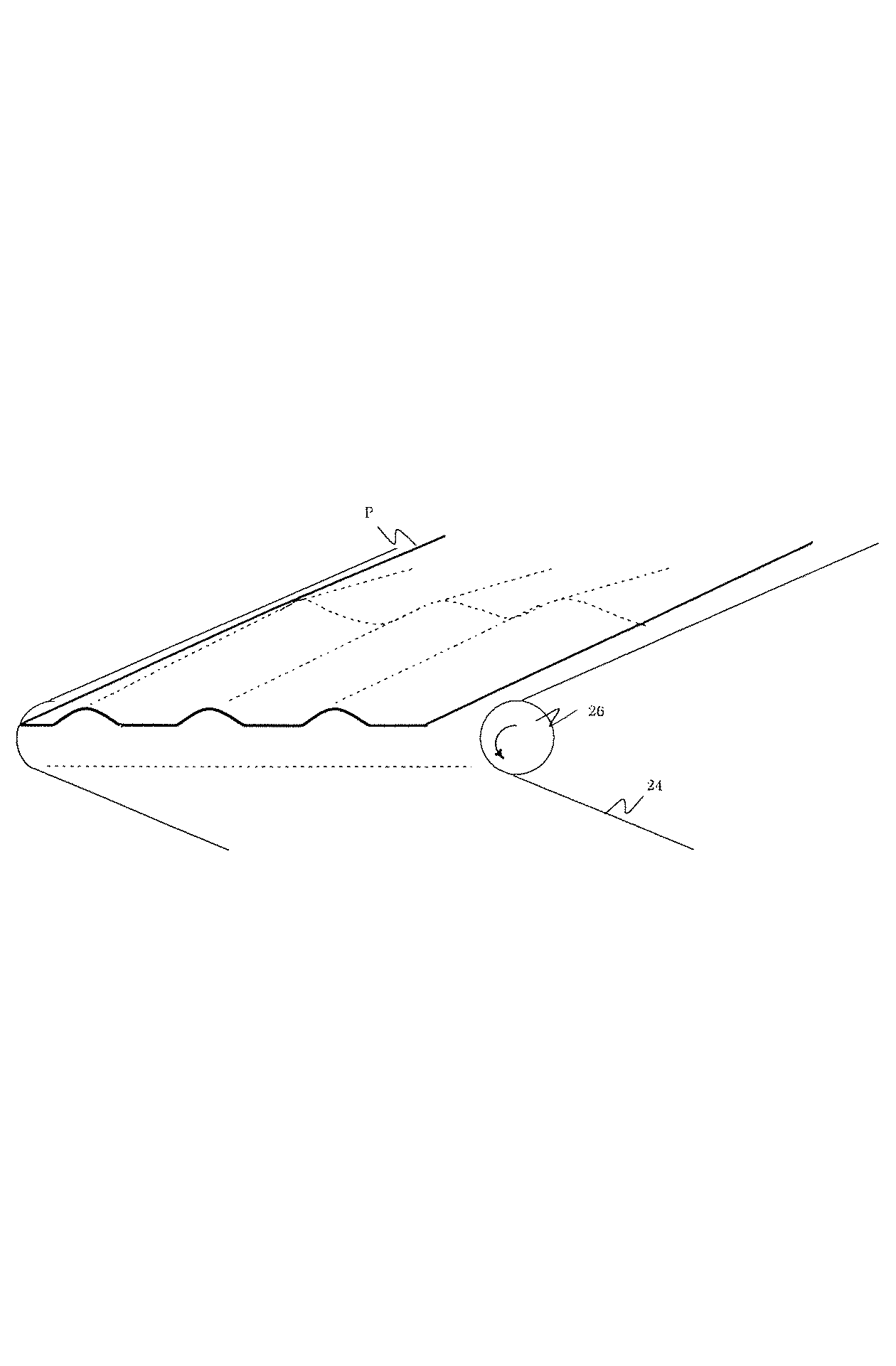
表1に示されるテーブルの判断基準の根拠は、図9で示される記録材のこしに対する転写ベルト24から分離可能な二次転写電流の値を求めた検討結果による。図9の横軸になっている紙のこしは、ガーレー式剛度測定器に熊谷理機工業株式会社製のAutoScanによって、JIS L 1096 で規定されている手法によって測定したガーレー式剛度の数値である。
The basis of the determination criteria of the table shown in Table 1 is based on the examination result obtained for the value of the secondary transfer current separable from the
図9に示すように、記録材の剛度(こし)が小さいほど転写ベルト24から分離できる二次転写電流は小さくなっている。例えば記録材へトナー像を転写するために40μAの電流を流すとき、記録材Pの剛度がガーレー式剛度測定器で測定した値で0.35mN
以上ないと分離が厳しくなるため、分離補助装置40により記録材のこしを強くする必要がある。
As shown in FIG. 9, the smaller the stiffness of the recording material, the smaller the secondary transfer current that can be separated from the
Otherwise, separation becomes severe, and it is necessary to strengthen the recording material by the
ガーレー式剛度測定器で測定した0.35mNという記録材の剛度は、一般ユーザーが記録材の厚さを管理するのに用いている坪量では60g/m2以上あれば持たせることができる数値である。このため、表1に示すように、二次転写電流が40μA以上で、記録材の坪量が60g/m2以下のものは、転写ベルト24からの分離が厳しくなるので、分離補助装置40を作動させる。
A recording material stiffness of 0.35 mN measured with a Gurley stiffness measuring instrument is a numerical value that can be provided if the basis weight used by general users to manage the thickness of the recording material is 60 g / m 2 or more. It is. For this reason, as shown in Table 1, when the secondary transfer current is 40 μA or more and the basis weight of the recording material is 60 g / m 2 or less, separation from the
また、記録材の坪量が40g/m2以下となると、ガーレー式剛度測定器で測定したこしの強さは、0.1mN以下のような非常に小さい値となる。このような値では、転写ベルト24から分離可能な二次転写電流は、10μA以下と転写不良が起こってしまうような値になってしまう。そこで、記録材の坪量が40g/m2以下のときは、記録材のこしを強くため、必ず分離補助装置40を作動させている。
Further, when the basis weight of the recording material is 40 g / m 2 or less, the strength of the strain measured with the Gurley stiffness measuring instrument is a very small value such as 0.1 mN or less. With such a value, the secondary transfer current separable from the
<画像形成時の制御>
図10は画像形成時の分離補助装置の制御のフローチャートである。図1に示すように、画像形成装置10における通常動作は、連続または間欠で画像形成が可能な状態である。通常動作時(転写時)には、図3の(a)に示すように、二次転写部N1及び吸着部N2は当接している。
<Control during image formation>
FIG. 10 is a flowchart of the control of the separation assisting device during image formation. As shown in FIG. 1, the normal operation in the
通常動作時において、表1に示す「コロ持ち上げ動作有」の転写条件では、図8に示すジャム検知センサ70が記録材先端を検知するまで(記録材先端が分離爪29に保持されるまで)は、突起の位置を転写ベルトにうねりを生じさせる位置にする。これによって記録材にもうねりを生じさせて記録材の剛度を上げて、転写ベルトからの記録材の分離性を上げている。記録材先端がジャム検知センサ70に検出されて、記録材にうねりが無くても転写ベルト24からの記録材の分離が確実になった時、先端コロ41の位置を転写ベルト24の内側面から離間させる。
Under normal operation, under the transfer condition “with roller lifting operation” shown in Table 1, until the
ただし、離間させる理由は、後述する停止モードにおける「転写ベルト24の停止中の変形を阻止するため」ではなく、「記録材Pに転写されたトナー像に対する電気的、機械的な影響を阻止するため」である。
However, the reason for the separation is not “in order to prevent the deformation of the
図7を参照して図10に示すように、制御部50は、ユーザー操作部102でユーザーが指定した記録材の坪量情報を読み取る(S11)。そして、ユーザーによって指定された記録材Pの坪量が60g/m2を超える場合(S12の60g/m2超)、分離補助装置40は、収納位置のまま保持して、転写ベルト24を持ち上げる動作を行わない(S18)。しかし、記録材Pの坪量が40g/m2未満(S12の40g/m2未満)の場合は、分離補助装置40をY1方向へ動かして、転写ベルト24を持ち上げた状態にする(S15)。
As shown in FIG. 10 with reference to FIG. 7, the
制御部50は、記録材Pが40g/m2以上60g/m2以下の場合(S12の40g/m2〜60g/m2)、二次転写電流値を読み取った上で(S13)分離補助装置40の動作を判断する。制御部50は、記録材Pが二次転写部N1に到達する直前に二次転写部N1に二次転写電流測定用の定電圧を印加しておき、記録材先端の二次転写電流値を読み取る。
Control unit 50, (40g / m 2 ~60g / m 2 of S12) when the recording material P is 40 g / m 2 or more 60 g / m 2 or less, in terms of reading the secondary transfer current value (S13) the separation assisting The operation of the
制御部50は、二次転写電流が40μA以上のときは(S14の40μA以上)分離補助装置40をY1方向へ回動させて転写ベルト24を持ち上げた状態にする。しかし、二次転写電流が40μA未満のときは(S14の40μA未満)、分離補助装置40を収納位置のまま保持する。(S18)。
When the secondary transfer current is 40 μA or more (40 μA or more in S14), the
また、画像のトナー像の間隔で分離すべき記録材が無い状態では、分離補助装置40によって転写ベルト24を持ち上げなくても良いため、分離補助装置40は、転写ベルト24と接触しない収納位置に待機している。
Further, in the state where there is no recording material to be separated at the interval of the toner images of the image, the
ところで、画像形成中、記録材Pが給送されているにもかかわらず、ジャム検知センサ70に所定時間以上にわたって記録材先端が検知されない場合、制御部50は、停止モードを実行して、画像形成装置10の動作を停止させる。このとき、記録材Pの搬送経路に設けた複数の通過センサによる記録材先端及び記録材後端の検出タイミングとタイムカウントに基づいて記録材Pの位置を把握して、記録材Pの残留位置に応じた停止モードを実行する。
By the way, if the leading edge of the recording material is not detected by the
また、近年の画像形成装置のプロセススピードの高速化に伴って緊急停止時における慣性が増加している。このため、画像形成中、記録材Pにうねりを与えるために分離補助装置40が作動していた場合、直ちに収納位置へ移動させると、図2の(e)に示すように、分離ローラ26による転写ベルト24の湾曲面で記録材Pの巻き付きが発生してしまう。
In addition, with the recent increase in process speed of image forming apparatuses, inertia during an emergency stop is increasing. For this reason, when the
画像形成装置10の場合、分離ローラ26の対向位置に転写ベルトクリーニング装置31が存在するので、緊急停止後、分離ローラ26による転写ベルト24の湾曲面に巻き付いた記録材Pを除去することが困難である。
In the case of the
そこで、画像形成中、分離補助装置40が図4の(b)に示すコロ持ち上げ位置にある場合に停止モードに移行した場合には、コロ持ち上げ位置のまま転写ベルト24を停止させることが提案された。しかし、この場合、転写ベルト24の停止後に転写ベルト24に掛かり続けるストレスが問題となる。この状態のまま長時間放置すると、転写ベルト24が変形し、最悪の場合、元に戻らないので吸着不良などが発生する。
Therefore, during image formation, when the
また、分離補助装置40を作動させる転写条件でありながら、たまたま上述の理由で、分離補助装置40が図4の(a)に示すコロ収納位置で待機していた場合にも問題がある。転写ベルト24の慣性によって搬送される記録材Pが分離補助装置40がコロ収納位置のまま転写ベルト24の湾曲面に突入して巻き付き、転写ベルトクリーニング装置31でジャムを発生して、ジャム記録材が取り出しづらい。
Further, there is a problem even when the
そこで、以下の実施例では、画像形成装置10の停止モードで、選択的に分離補助装置40を作動させて、転写ベルト24の慣性による記録材Pの巻き付きジャムを防ぎつつ、転写ベルト24の停止後のストレスを回避している。
Therefore, in the following embodiment, the
<実施例1>
図11は実施例1の停止モードの制御のフローチャートである。図12は分離補助装置の動作タイミングの説明図である。
<Example 1>
FIG. 11 is a flowchart of stop mode control according to the first embodiment. FIG. 12 is an explanatory diagram of the operation timing of the separation assisting device.
実施例1における停止モードは、記録材Pのジャムが発生しても画像形成装置10の制御が可能な状態を指し、停電等による画像形成装置10の制御が不可能な場合は除く。実施例1の停止モードが実行されると、図3の(b)に示すように、二次転写部N1及び吸着部N2が離間されて、さらに記録材Pを搬送して記録材Pの先端を分離爪29に乗せた状態で転写ベルト24が停止される。
The stop mode in the first embodiment refers to a state in which the
図1を参照して図7に示すように、実行部の一例である制御部50は、画像形成動作中に異常が生じたときには、停止モードを実行する。停止モードでは、分離補助装置40により押し上げた状態で転写ベルト24を回転させてから、転写ベルト24の回転を停止する。停止モードでは、先端コロ41を外側へ突き出して転写ベルト24から記録材Pを分離させた後に、先端コロ41の突き出し解除及び転写ベルト24の停止を実行する。
As shown in FIG. 7 with reference to FIG. 1, the
検出手段の一例であるジャム検知センサ70は、分離爪29に先端を保持された状態の記録材Pを検出可能である。停止モードでは、記録材Pの先端が分離ローラに進入した後に分離補助装置40による押し上げを解除し、ジャム検知センサ70が記録材Pの先端を検出した後に転写ベルト24の回転を停止させる。停止モードでは、二次転写部N1のニップ圧力を解除した後に先端コロ41による転写ベルト24の押し上げを実行させる。停止モードでは、転写ベルト24から吸着ローラ28を離間した後に先端コロ41による転写ベルト24の押し上げを実行させる。
The
実施例1では、転写ベルト24と分離爪29との間で記録材Pがジャムした場合、先端コロ41による転写ベルト24の押し上げを行うことなく、直ちに転写ベルト24の回転を停止させる。
In the first exemplary embodiment, when the recording material P is jammed between the
実施例1では、二次転写部N1で記録材Pがジャムした場合、先端コロ41による転写ベルト24の押し上げを行うことなく、直ちに転写ベルト24の回転を停止させる。
In the first embodiment, when the recording material P is jammed at the secondary transfer portion N1, the rotation of the
実施例1では、記録材Pの剛性が所定の水準より高い場合には、先端コロ41による転写ベルト24の押し上げを行うことなく、分離爪29に記録材Pの先端が到達した後に転写ベルト24の回転を停止させる。
In Example 1, when the rigidity of the recording material P is higher than a predetermined level, the
制御部50は、停止モードにおける分離補助装置40の動作位置を制御する。制御部50は、上述した表1のテーブルに基づいて、停止モードにおける分離補助装置40の作動/非作動を判断し、図11で示されるフローに従って転写ベルト24の緊急停止を制御する。制御部50は、ユーザー操作部102を通じて指定された記録材Pの坪量情報に基づいて、停止モードにおける分離補助装置40の作動/非作動を判断する。制御部50は、転写電源D9によって読み取られる二次転写電流値に基づいて停止モードにおける分離補助装置40の作動/非作動を判断する。
The
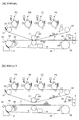
制御部50は、停止モードにおける中間転写ベルト6と転写ベルト24の接離動作とを制御する。制御部50は、記録材Pを送るレジストローラ8前の通過センサ17によって得られる記録材Pの先端位置情報、レジストローラ8の記録材送りタイミング、及びタイムカウントによって刻々の記録材位置を認識する。図12に示すように、記録材Pの位置に応じて、分離補助装置40の動作位置および転写ベルト24の接離動作の時間的なタイミングが制御される。図12中、(a)は画像形成時、(b)は停止モード時である。
The
制御部50は、画像形成装置10の緊急停止時においても、記録材先端が分離爪29を越えてジャム検知センサ70に検知されるまでは、分離補助装置40の位置を転写ベルト24にうねりを生じさせる位置にする。そして、記録材先端が分離爪29を越えて、記録材Pにうねりが無くても転写ベルト24からの記録材Pの分離が確実になった時点で分離補助装置40を転写ベルト24にうねりが生じない位置にする。
Even when the
このような停止モードを行うことで、記録材Pのうねりを与えて、転写ベルト24から記録材Pを確実に分離させ、緊急停止時における転写ベルト24の分離部における巻き付きジャムが防止される。
By performing such a stop mode, the recording material P is swelled to reliably separate the recording material P from the
図11に示すように、記録材Pのジャムが検知されると(S21)、制御部50は、画像形成を中断して停止モードを強制実行し、図3の(b)に示すように、直ちに二次転写部N1と吸着部N2を当接解除する(S22)。
As shown in FIG. 11, when a jam of the recording material P is detected (S21), the
実施例1の停止モードは、転写ベルト24上のジャムしていない記録材Pを取り出し易い位置に誘導すること、および転写ベルト24の停止時の慣性回転による二次的な記録材ジャムの発生を阻止することを目的としている。このため、実施例1の停止モードは、記録材カセット15からレジストローラ8までの搬送経路における記録材のジャム、定着装置13〜排出部〜不図示の後処理装置における記録材のジャムに応答して実行される。
In the stop mode of the first embodiment, the non-jammed recording material P on the
これに対して、ニ次転写部N1で記録材Pのジャムが発生した場合は、実施例1の停止モードは実行しない。転写ベルト24を回転させるほど事態が深刻になるので、直ちに転写ベルト24の回転を停止する。また、二次転写部N1で記録材に皺が入ると、転写ベルト24からの剥離、つまりユーザーによるジャム処理が容易となり、分離補助装置40に頼らなくて済む。
In contrast, when the recording material P is jammed in the secondary transfer portion N1, the stop mode of the first embodiment is not executed. Since the situation becomes more serious as the
また、転写ベルト24と分離爪29の間で記録材Pがジャムした場合も実施例1の停止モードは実行しない。もはや手遅れなので、先端コロ41による転写ベルト24の押し上げを行うことなく、直ちに転写ベルト24の回転を停止させる。
Further, even when the recording material P is jammed between the
制御部50は、図12の(b)に示すように、画像形成時に二次転写バイアスをONして記録材Pの坪量を取得している。停止モードの開始後、その取得した記録材Pの坪量に基づいて分離補助装置40の動作を判断する(S23)。坪量が60g/m2を超えてこしが強い記録材Pの場合(S23の60g/m2超)、分離補助装置40を図4の(b)に示すコロ収納位置のまま保持して、転写ベルト24を持ち上げる動作を行わない(S29)。しかし、坪量が40g/m2未満でこしが極端に小さい記録材の場合(S23の40g/m2未満)、分離補助装置40をY1方向へ動かして、図4の(a)に示すように、転写ベルト24を持ち上げた状態に移行させる(S26)。
As shown in FIG. 12B, the
制御部50は、記録材Pが40〜60g/m2の間の場合(S23の40g/m2〜60g/m2)、画像形成中に読み取っていた二次転写電流値(S24)に基づいて分離補助装置40の動作を判断する(S25)。
制御部50は、二次転写電流値が40μA以上の場合(S14の40μA以上)、分離補助装置40をY1方向へ動かして、図4の(a)に示すように、転写ベルト24を持ち上げた状態に移行させる。しかし、二次転写電流値が40μA未満の場合(S14の40μA未満)、図4の(b)に示すように、分離補助装置40をコロ収納位置のまま保持して転写ベルト24を持ち上げるような動作は行わない(S29)。
When the secondary transfer current value is 40 μA or more (40 μA or more in S14), the
制御部50は、分離ローラ26による転写ベルト24の湾曲面で分離が困難な条件では、上述したように、分離補助装置40を図4の(a)に示すコロ持ち上げ位置に移行させて、転写ベルト24からの薄紙の分離を補助する。
As described above, the
その後、記録材Pの先端が分離爪29に到達してジャム検知センサ70に検知されると(S28の分離爪に到達)、分離補助装置40を収納する動作を行うための信号が制御部50より分離補助装置40に伝達される(S29)。分離補助装置40は、信号を受けて、転写ベルト24を持ち上げているコロ持ち上げ位置から、転写ベルト24と分離補助装置40が離間しているコロ収納位置へ移行する(S29)。
Thereafter, when the leading edge of the recording material P reaches the
画像形成時と同様に、表1に示す「動作なし」の条件の場合、分離補助装置40の補助がなくても記録材Pが転写ベルト24から曲率分離して分離爪29に到達する。このため、分離補助装置40は、図4の(b)に示すように、転写ベルト24と接触しないコロ収納位置に来る。分離補助装置40は、転写ベルト24の押し上げを解除している。
Similarly to the image formation, in the case of the “no operation” condition shown in Table 1, the recording material P is separated from the
図12の(b)に示すように、実施例1の停止モードの開始時に分離補助装置40が転写ベルト24を既に突き上げている場合(S28の分離爪に未到達)、図4の(a)に示すように、その突き上げ状態を保持する(S26)。そして、ジャム検知センサ70によって記録材Pの先端が検出されて、転写ベルト24から記録材Pが正常に分離されたことが確認されると(S28の分離爪に到達)、制御部50から、分離補助装置40による突き上げを解除させる動作信号が伝達される。
As shown in FIG. 12B, when the
これにより、分離補助装置40が転写ベルト24から脱されたコロ収納位置となり、その後に転写ベルト24が停止される(S30)。このときの状態を示しているのが図4の(b)である。図1に示すように、転写ベルト24上で停止した記録材Pは、定着装置13を記録材の搬送方向へ退去させて形成したスペースを通じて転写ベルト24から引き剥がして除去される。
As a result, the
以上の動作により、ジャム等による緊急停止時に分離ローラ26位置における巻き付きジャム防止が可能となり、転写ベルト24上に残った記録材の処理が容易になる。
With the above operation, it is possible to prevent a winding jam at the position of the
<実施例2>
図13は実施例2の停止モードにおける分離補助装置の動作タイミングの説明図である。図14は実施例2における分離補助装置の動作の説明図である。実施例2では、画像形成装置10において、実施例1よりも少し早いタイミングで図11に示す停止モードが開始した場合を説明する。
<Example 2>
FIG. 13 is an explanatory diagram of the operation timing of the separation assisting device in the stop mode of the second embodiment. FIG. 14 is an explanatory diagram of the operation of the separation assisting device according to the second embodiment. In the second embodiment, the case where the stop mode shown in FIG. 11 starts in the
図13に示すように、分離補助装置40がコロ収納位置にある状態で停止モードが開始された場合も、上述した表1の「コロ持ち上げ動作有」の条件であれば、分離補助装置40をコロ持ち上げ位置に移行させる。その際の分離補助装置40の動作および転写ベルト24の接離動作のタイミングが図13に示される。
As shown in FIG. 13, even when the stop mode is started in a state where the
図14の(a)に示すように、ジャム等による緊急停止時に、記録材Pの先端が分離補助装置40によって突き上げられる位置まで到達していない場合がある。この場合、図14の(b)に示すように、分離補助装置40をコロ持ち上げ状態に移行させて転写ベルト24により記録材Pを搬送する。そして、図8に示すように分離爪29を越えた位置にあるジャム検知センサ70によって、記録材Pが転写ベルト24から正常に分離されたことが確認されると、制御部50は、図4の(b)に示すように、分離補助装置40をコロ収納位置に戻す。これにより、転写ベルト24と先端コロ41は脱された状態となり、その後に転写ベルト24が停止される。このときの状態を示しているのが図14の(c)である。
As shown in FIG. 14A, there is a case where the leading end of the recording material P has not reached the position where it is pushed up by the
以上の動作により、ジャム等による緊急停止時に分離ローラ26位置における巻き付きジャム防止が可能となり、転写ベルト24上に残った記録材の処理が容易になる。
With the above operation, it is possible to prevent a winding jam at the position of the
<実施例3>
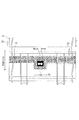
図15は転写ベルトによる記録材の搬送状態の俯瞰図である。図16は実施例3の停止モードにおける分離補助装置の動作タイミングの説明図である。実施例3では、画像形成装置10において、実施例1よりも短い搬送間隔で記録材を給送して連続画像形成をしている際に図11に示す停止モードが開始した場合を説明する。
<Example 3>
FIG. 15 is a bird's-eye view of the recording material transported by the transfer belt. FIG. 16 is an explanatory diagram of the operation timing of the separation assisting device in the stop mode of the third embodiment. In the third embodiment, the case where the stop mode shown in FIG. 11 is started when the
図15に示すように、上述した表1の「コロ持ち上げ動作有」の条件での連続画像形中、矢印R3方向に記録材P1が搬送され、短い間隔(紙間)を隔てて続く記録材P2の先端も転写ベルト24に搬送されている。実施例3では、連続通紙状態であるため、停止モードの開始時に2枚目の記録材P2が転写ベルト24上に残留した状態である。
As shown in FIG. 15, the recording material P1 is conveyed in the direction of arrow R3 in the continuous image shape under the condition of “with roller lifting operation” in Table 1 described above, and continues with a short interval (interval between sheets). The leading end of P2 is also conveyed to the
ここで、記録材P1、P2は、A5サイズの坪量40〜60g/m2の記録材であり、分離補助装置40を作動させないと転写ベルト24から分離しない環境条件であるとする。転写ベルト24のサイズは、幅が330mmで、入口ローラ25と分離ローラ26の軸間距離は250mmである。また、記録材P1、P2の搬送間隔は30mmである。
Here, it is assumed that the recording materials P1 and P2 are A5 size recording materials having a basis weight of 40 to 60 g /
図16の(a)に示すように、記録材ジャムが発生して停止モードが開始されたとする。このとき、記録材P1は、分離ローラ26の分離部で巻き付きジャムを発生する可能性がある。さらに、吸着電源D28は、負極性の吸着電圧を吸着ローラ28に印加して記録材Pを負極性に帯電させている。このため、ジャム発生時に二次転写部N1を通過している記録材P1の部分と転写ベルト24の吸着力は、吸着部N2における記録材P1と転写ベルト24の吸着力より大きくなっている。したがって、記録材P1は、分離ローラ26の分離部で巻き付きジャムを発生する可能性がさらに高まっている。
As shown in FIG. 16A, it is assumed that the recording material jam occurs and the stop mode is started. At this time, the recording material P <b> 1 may cause a winding jam at the separation portion of the
そこで、実施例3では、ジャム発生時に記録材P1の先端が二次転写部N1を通過している場合は、すべて図14の(b)に示すように、分離補助装置40をコロ持ち上げ状態に移行させて転写ベルト24からの分離を確実にする。そして、図14の(c)に示すように、記録材P1のみを転写ベルト24から分離させた状態で転写ベルト24を停止させる。この場合、後続の記録材P2については、吸着部N2より上流側のレジストローラ8から取り除かれることになる。
Therefore, in the third embodiment, when the leading edge of the recording material P1 passes through the secondary transfer portion N1 when a jam occurs, the
<実施例4>
図1に示すように、実施例3の停止モードにおいて、1枚目の記録材P1を定着装置13に送り込んで、後続の記録材P2の先端が分離爪29にかかる位置で転写ベルト24を停止させてもよい。
<Example 4>
As shown in FIG. 1, in the stop mode of the third embodiment, the first recording material P <b> 1 is sent to the fixing
図16の(b)に示すように、実施例4では、記録材P1が通過して後続の記録材P2の先端が分離し終わるまで、分離補助装置40をコロ持ち上げ状態に保持する。そして、後続の記録材P2の先端が分離爪29を越えてジャム検知センサ70に検出されたタイミングで転写ベルト24を停止させ、ほぼ同時に分離補助装置40を「コロ収納位置」に移行させている。
As shown in FIG. 16B, in the fourth embodiment, the
以上の動作により、ジャム等による緊急停止時に分離ローラ26位置における巻付きジャム防止が可能となり、転写ベルト24上に残った記録材の処理が容易になる。
With the above operation, it is possible to prevent a winding jam at the position of the
1Y、1M、1C、1K 感光ドラム
2Y、2M、2C、2K コロナ帯電器
3Y、3M、3C、3K 露光装置
4Y、4M、4C、4K 現像装置
5Y、5M、5C、5K 一次転写ローラ
6 中間転写ベルト、8 レジストローラ
9 二次転写ローラ、11 ドラムクリーニング装置
12 ベルトクリーニング装置、17 センサ
20 駆動ローラ、21 二次転写対向ローラ、22 テンションローラ
24 転写ベルト、25 入口ローラ、26 分離ローラ
28 吸着ローラ、29 分離爪、31 ベルトクリーニング装置
40 分離補助装置、41 先端コロ、50 制御部
60、70 ジャム検知センサ、D9 転写電源、D30 吸着電源
P 記録材、N1 二次転写部、N2 吸着部
1Y, 1M, 1C,
Claims (7)
前記ベルト部材に担持されている記録材を前記ベルト部材から分離するために、前記ベルト部材の回転方向において前記分離ローラよりも上流側で前記転写部より下流側のベルト面を前記ベルト部材の幅方向において局所的に押し上げ可能である押し上げ手段と、
画像形成動作中に異常が生じたときには、画像形成動作を停止した後に、前記押し上げ手段を押し上げた状態でベルト部材を回転させてからベルト部材の回転を停止する停止モードを実行する実行部と、を有することを特徴とする画像形成装置。 An image carrier, a rotatable belt member that is stretched, and a transfer unit that forms a transfer unit that transfers a toner image formed on the image carrier to a recording material carried and conveyed by the belt member; In an image forming apparatus comprising: a separation roller that stretches a belt member and is capable of separating the recording material carried on the belt member from the belt member;
In order to separate the recording material carried on the belt member from the belt member, the belt surface on the upstream side of the separation roller and on the downstream side of the transfer portion in the rotation direction of the belt member has a width of the belt member. A push-up means that is locally pushable in the direction;
An execution unit for executing a stop mode in which rotation of the belt member is stopped after rotating the belt member in a state in which the push-up means is pushed up after stopping the image forming operation when an abnormality occurs during the image forming operation; An image forming apparatus comprising:
前記停止モードでは、記録材の先端が前記分離ローラに進入した後に前記押し上げ手段による押し上げを解除し、前記検出手段が記録材の先端を検出した後に前記ベルト部材の回転を停止させることを特徴とする請求項1記載の画像形成装置。 A guide member capable of guiding the leading end of the recording material separated from the belt member and holding the separated state; and a detecting means capable of detecting the recording material in a state where the leading end is held by the guide member;
In the stop mode, after the leading edge of the recording material enters the separation roller, the pushing-up by the pushing-up means is released, and the rotation of the belt member is stopped after the detecting means detects the leading edge of the recording material. The image forming apparatus according to claim 1.
前記停止モードでは、前記転写部のニップ圧力を解除した後に前記押し上げ手段を押し上げることを特徴とする請求項2記載の画像形成装置。 The transfer unit is configured to be able to release the nip pressure of the recording material,
3. The image forming apparatus according to claim 2, wherein, in the stop mode, the push-up unit is pushed up after releasing the nip pressure of the transfer unit.
前記停止モードでは、前記ベルト部材から前記帯電手段を離間した後に前記押し上げ手段を押し上げることを特徴とする請求項2又は3記載の画像形成装置。 Charging that is arranged so as to be able to come into contact with and separate from the outer surface of the belt member and holds the recording material fed to the transfer portion with the belt member at the time of image formation and electrically adsorbs to the belt member With means,
4. The image forming apparatus according to claim 2, wherein, in the stop mode, the push-up unit is pushed up after the charging unit is separated from the belt member.
Priority Applications (2)
| Application Number | Priority Date | Filing Date | Title |
|---|---|---|---|
| JP2010280197A JP5677074B2 (en) | 2010-12-16 | 2010-12-16 | Image forming apparatus |
| US13/324,021 US8838012B2 (en) | 2010-12-16 | 2011-12-13 | Image forming apparatus with belt member pushing |
Applications Claiming Priority (1)
| Application Number | Priority Date | Filing Date | Title |
|---|---|---|---|
| JP2010280197A JP5677074B2 (en) | 2010-12-16 | 2010-12-16 | Image forming apparatus |
Publications (2)
| Publication Number | Publication Date |
|---|---|
| JP2012128228A true JP2012128228A (en) | 2012-07-05 |
| JP5677074B2 JP5677074B2 (en) | 2015-02-25 |
Family
ID=46234601
Family Applications (1)
| Application Number | Title | Priority Date | Filing Date |
|---|---|---|---|
| JP2010280197A Expired - Fee Related JP5677074B2 (en) | 2010-12-16 | 2010-12-16 | Image forming apparatus |
Country Status (2)
| Country | Link |
|---|---|
| US (1) | US8838012B2 (en) |
| JP (1) | JP5677074B2 (en) |
Cited By (5)
| Publication number | Priority date | Publication date | Assignee | Title |
|---|---|---|---|---|
| EP2937736A1 (en) | 2014-04-02 | 2015-10-28 | Canon Kabushiki Kaisha | Image forming apparatus |
| EP2940530A1 (en) | 2014-04-02 | 2015-11-04 | Canon Kabushiki Kaisha | Image forming apparatus |
| US9766574B2 (en) | 2014-09-26 | 2017-09-19 | Canon Kabushiki Kaisha | Image forming apparatus |
| JP2020001851A (en) * | 2018-06-26 | 2020-01-09 | 理想科学工業株式会社 | Transfer device |
| JP2023041275A (en) * | 2021-09-13 | 2023-03-24 | コニカミノルタ株式会社 | image forming device |
Families Citing this family (3)
| Publication number | Priority date | Publication date | Assignee | Title |
|---|---|---|---|---|
| EP2495618A1 (en) * | 2009-10-29 | 2012-09-05 | Canon Kabushiki Kaisha | Image formation apparatus |
| US10054895B2 (en) * | 2015-05-14 | 2018-08-21 | Ricoh Company, Ltd. | Image forming apparatus and image forming method |
| JP2018146893A (en) * | 2017-03-08 | 2018-09-20 | キヤノン株式会社 | Image forming apparatus |
Citations (4)
| Publication number | Priority date | Publication date | Assignee | Title |
|---|---|---|---|---|
| JPH07157141A (en) * | 1993-12-09 | 1995-06-20 | Minolta Co Ltd | Fixing jam treatment method |
| JPH1124341A (en) * | 1997-07-09 | 1999-01-29 | Toshiba Corp | Image forming device |
| JP2000242090A (en) * | 1999-02-18 | 2000-09-08 | Canon Inc | Image forming device |
| JP2003307981A (en) * | 2002-02-15 | 2003-10-31 | Sharp Corp | Image forming device |
Family Cites Families (11)
| Publication number | Priority date | Publication date | Assignee | Title |
|---|---|---|---|---|
| JP2607117B2 (en) * | 1988-04-05 | 1997-05-07 | キヤノン株式会社 | Image forming device |
| JP2750009B2 (en) * | 1991-02-12 | 1998-05-13 | キヤノン株式会社 | Image forming device |
| JPH05119636A (en) | 1991-10-24 | 1993-05-18 | Canon Inc | Image forming device |
| JPH05341664A (en) | 1992-06-08 | 1993-12-24 | Canon Inc | Image forming device |
| US5893657A (en) * | 1992-12-28 | 1999-04-13 | Canon Kabushiki Kaisha | Image forming apparatus with sheet conveying apparatus that facilitates jam recovery |
| JPH07210015A (en) * | 1994-01-11 | 1995-08-11 | Canon Inc | Image forming device |
| JPH0915987A (en) | 1995-06-28 | 1997-01-17 | Canon Inc | Image forming device |
| JPH0916024A (en) * | 1995-06-30 | 1997-01-17 | Minolta Co Ltd | Image forming device |
| JP3303622B2 (en) * | 1995-09-20 | 2002-07-22 | 富士ゼロックス株式会社 | Thick paper conveying method and image forming apparatus using the method |
| US5822665A (en) * | 1996-05-16 | 1998-10-13 | Fuji Xerox Co., Ltd. | Image forming apparatus having means for preventing vibration of a transfer film caused from the operation of a separating device |
| JP2000267519A (en) | 1999-03-15 | 2000-09-29 | Konica Corp | Double-sided image forming device |
-
2010
- 2010-12-16 JP JP2010280197A patent/JP5677074B2/en not_active Expired - Fee Related
-
2011
- 2011-12-13 US US13/324,021 patent/US8838012B2/en not_active Expired - Fee Related
Patent Citations (4)
| Publication number | Priority date | Publication date | Assignee | Title |
|---|---|---|---|---|
| JPH07157141A (en) * | 1993-12-09 | 1995-06-20 | Minolta Co Ltd | Fixing jam treatment method |
| JPH1124341A (en) * | 1997-07-09 | 1999-01-29 | Toshiba Corp | Image forming device |
| JP2000242090A (en) * | 1999-02-18 | 2000-09-08 | Canon Inc | Image forming device |
| JP2003307981A (en) * | 2002-02-15 | 2003-10-31 | Sharp Corp | Image forming device |
Cited By (9)
| Publication number | Priority date | Publication date | Assignee | Title |
|---|---|---|---|---|
| EP2937736A1 (en) | 2014-04-02 | 2015-10-28 | Canon Kabushiki Kaisha | Image forming apparatus |
| EP2940530A1 (en) | 2014-04-02 | 2015-11-04 | Canon Kabushiki Kaisha | Image forming apparatus |
| US9658577B2 (en) | 2014-04-02 | 2017-05-23 | Canon Kabushiki Kaisha | Image forming apparatus having transfer belt rollers of specific shapes |
| US9678459B2 (en) | 2014-04-02 | 2017-06-13 | Canon Kabushiki Kaisha | Image forming apparatus |
| US9766574B2 (en) | 2014-09-26 | 2017-09-19 | Canon Kabushiki Kaisha | Image forming apparatus |
| JP2020001851A (en) * | 2018-06-26 | 2020-01-09 | 理想科学工業株式会社 | Transfer device |
| JP7199165B2 (en) | 2018-06-26 | 2023-01-05 | 理想科学工業株式会社 | Conveyor |
| JP2023041275A (en) * | 2021-09-13 | 2023-03-24 | コニカミノルタ株式会社 | image forming device |
| JP7786088B2 (en) | 2021-09-13 | 2025-12-16 | コニカミノルタ株式会社 | Image forming device |
Also Published As
| Publication number | Publication date |
|---|---|
| US8838012B2 (en) | 2014-09-16 |
| US20120155902A1 (en) | 2012-06-21 |
| JP5677074B2 (en) | 2015-02-25 |
Similar Documents
| Publication | Publication Date | Title |
|---|---|---|
| JP5677074B2 (en) | Image forming apparatus | |
| JP5031451B2 (en) | Transfer device and image forming apparatus | |
| JP5208280B2 (en) | Image forming apparatus | |
| JP2004157532A (en) | Image forming device | |
| JP2001215859A (en) | Image forming device | |
| US6957022B2 (en) | Image forming apparatus | |
| US6347196B1 (en) | Image sticking reducing method and apparatus | |
| JP2012123251A (en) | Image forming apparatus | |
| JP3303622B2 (en) | Thick paper conveying method and image forming apparatus using the method | |
| JP4259163B2 (en) | Image forming apparatus | |
| US8660446B2 (en) | Image forming apparatus | |
| EP2397912B1 (en) | Image forming apparatus | |
| US8626043B2 (en) | Image forming apparatus and transfer device | |
| JP5292369B2 (en) | Image forming apparatus | |
| JP4972429B2 (en) | Image forming apparatus | |
| JP5258862B2 (en) | Image forming apparatus | |
| JP5267930B2 (en) | Scorotron charging device, image forming apparatus and process cartridge | |
| JP2002055536A (en) | Cleaning device, belt device, and image forming device | |
| JP2013077005A (en) | Image forming apparatus | |
| JP2020086012A (en) | Image forming device | |
| JP2014021137A (en) | Image forming apparatus | |
| JP5377782B2 (en) | Image forming apparatus | |
| JP2003223086A (en) | Image forming apparatus with cleaning function | |
| JP2000181320A (en) | Electrophotographic device for double-sided recording | |
| JP4822341B2 (en) | Image forming apparatus |
Legal Events
| Date | Code | Title | Description |
|---|---|---|---|
| RD04 | Notification of resignation of power of attorney |
Free format text: JAPANESE INTERMEDIATE CODE: A7424 Effective date: 20130228 |
|
| A621 | Written request for application examination |
Free format text: JAPANESE INTERMEDIATE CODE: A621 Effective date: 20131206 |
|
| A977 | Report on retrieval |
Free format text: JAPANESE INTERMEDIATE CODE: A971007 Effective date: 20140822 |
|
| A131 | Notification of reasons for refusal |
Free format text: JAPANESE INTERMEDIATE CODE: A131 Effective date: 20140902 |
|
| A521 | Written amendment |
Free format text: JAPANESE INTERMEDIATE CODE: A523 Effective date: 20141031 |
|
| TRDD | Decision of grant or rejection written | ||
| A01 | Written decision to grant a patent or to grant a registration (utility model) |
Free format text: JAPANESE INTERMEDIATE CODE: A01 Effective date: 20141202 |
|
| A61 | First payment of annual fees (during grant procedure) |
Free format text: JAPANESE INTERMEDIATE CODE: A61 Effective date: 20141226 |
|
| LAPS | Cancellation because of no payment of annual fees |