JP2012128487A - Communication system, relay communication device, combination of relay communication device and electromagnetic induction communication device, electromagnetic induction communication device, and information storage medium - Google Patents
Communication system, relay communication device, combination of relay communication device and electromagnetic induction communication device, electromagnetic induction communication device, and information storage medium Download PDFInfo
- Publication number
- JP2012128487A JP2012128487A JP2010276879A JP2010276879A JP2012128487A JP 2012128487 A JP2012128487 A JP 2012128487A JP 2010276879 A JP2010276879 A JP 2010276879A JP 2010276879 A JP2010276879 A JP 2010276879A JP 2012128487 A JP2012128487 A JP 2012128487A
- Authority
- JP
- Japan
- Prior art keywords
- communication device
- relay
- communication
- storage medium
- information storage
- Prior art date
- Legal status (The legal status is an assumption and is not a legal conclusion. Google has not performed a legal analysis and makes no representation as to the accuracy of the status listed.)
- Granted
Links
Images


Landscapes
- Near-Field Transmission Systems (AREA)
Abstract
【課題】電磁誘導方式で通信する通信システムを低コストで実現できる通信システム、中継通信装置、中継通信装置及び電磁誘導通信装置の組み合わせ、電磁誘導通信装置、情報記憶媒体を提供する。
【解決手段】中継自動改札システム1は、ICカード40が、電磁誘導方式で通信可能なICチップ41と、導電プレート42L,42Rとを備え、中継通信装置30が、中継ループアンテナ31と、ICカード40の一対の導電プレート42L,42Rと静電結合し、導電性を有する一対の導電レール32L,32Rとを備え、電磁誘導改札機20が、中継ループアンテナとの間で電磁誘導方式により通信する改札ループアンテナ21aと、中継通信装置30との間で電磁誘導方式により通信し、中継通信装置30及びICカード40の間で静電結合することにより、ICカード40のICチップ41との間で通信処理をする改札制御部27とを備える。
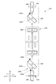
【選択図】図1Provided are a communication system, a relay communication device, a combination of a relay communication device and an electromagnetic induction communication device, an electromagnetic induction communication device, and an information storage medium capable of realizing a communication system communicating by an electromagnetic induction method at low cost.
In an automatic relay ticket gate system, an IC card includes an IC chip capable of communicating by electromagnetic induction and conductive plates, and a relay communication device includes a relay loop antenna, an IC, A pair of conductive rails 32L and 32R that are electrostatically coupled to the pair of conductive plates 42L and 42R of the card 40 and have conductivity, and the electromagnetic induction ticket gate 20 communicates with the relay loop antenna by an electromagnetic induction method. The ticket gate loop antenna 21a and the relay communication device 30 communicate with each other by an electromagnetic induction method, and are electrostatically coupled between the relay communication device 30 and the IC card 40, thereby being connected to the IC chip 41 of the IC card 40. And a ticket gate control unit 27 for performing communication processing.
[Selection] Figure 1
Description
本発明は、電磁誘導方式を利用する通信システム、中継通信装置、中継通信装置及び電磁誘導通信装置の組み合わせ、電磁誘導通信装置、情報記憶媒体に関するものである。 The present invention relates to a communication system using an electromagnetic induction system, a relay communication device, a relay communication device, a combination of an electromagnetic induction communication device, an electromagnetic induction communication device, and an information storage medium.
従来、利用者が所持するICカードを電磁誘導方式によって読み取る(又は書き込む)通信システムがあった(例えば特許文献1)。このような通信システムのICカードは、少なくとも非接触通信機能を有するICチップとアンテナコイルにより構成されており、ICカード内に具備されたICチップは、リーダライタから送出された信号より駆動電力の供給を受け、リーダライタから送出されるアナログ信号を受信しデジタル変換し、応答信号を返送することによりデータ送受信を実現している。非接触ICカードは、交通システム、電子マネー、社員証システム、物流管理等の各種システムで用いられている。
非接触ICカード用いた通信方式としては、通信周波数帯域に応じて、電磁結合方式、静電結合方式、電磁誘導方式、電波方式が用いられており、カード形態の非接触IC通信システムでは電磁誘導方式が主流となっている。
しかし、電磁誘導方式の通信システムは、ICカードのアンテナコイルをエッチング等により形成するため高コストであった。
一方、利用者が所持するICカードを静電結合方式によって、読み取る(又は書き込む)通信システムがあった(例えば特許文献2)。
しかし、静電結合方式の通信システムの情報記憶媒体及び読取書込装置間の通信距離は、電磁誘導方式の通信システムと比較すると短い。このため、電磁誘導方式の通信システムは、情報記憶媒体が読取書込装置から少し離れた状態で通信が開始されるのに対して、静電結合方式の通信システムは、情報記憶媒体をリーダライタにほぼ密着させないと通信が開始されない。そのため、情報記憶媒体及び読取書込装置の間の通信時間は、電磁誘導方式の通信システムと同等であっても、利用者が体感する処理時間は、情報記憶媒体をより近づけるために要する時間の分、長くなる。これにより、静電結合方式の通信システムを例えば自動改札機に利用すると、ゲートでの混雑を招くおそれがあった。
Conventionally, there has been a communication system that reads (or writes) an IC card possessed by a user by an electromagnetic induction method (for example, Patent Document 1). An IC card of such a communication system is composed of at least an IC chip having a non-contact communication function and an antenna coil, and the IC chip provided in the IC card has driving power from a signal transmitted from a reader / writer. Data is transmitted / received by receiving an analog signal sent from the reader / writer, converting it to digital, and returning a response signal. Non-contact IC cards are used in various systems such as transportation systems, electronic money, employee ID systems, and logistics management.
As a communication method using a non-contact IC card, an electromagnetic coupling method, an electrostatic coupling method, an electromagnetic induction method, and a radio wave method are used according to the communication frequency band. In a card-type non-contact IC communication system, electromagnetic induction is used. The method has become mainstream.
However, the electromagnetic induction type communication system is expensive because the antenna coil of the IC card is formed by etching or the like.
On the other hand, there has been a communication system that reads (or writes) an IC card possessed by a user by an electrostatic coupling method (for example, Patent Document 2).
However, the communication distance between the information storage medium and the reading / writing device of the electrostatic coupling communication system is shorter than that of the electromagnetic induction communication system. For this reason, the electromagnetic induction communication system starts communication with the information storage medium slightly separated from the reading / writing device, whereas the electrostatic coupling communication system uses the information storage medium as a reader / writer. Communication is not started unless it is almost in close contact. Therefore, even if the communication time between the information storage medium and the reading / writing device is equivalent to that of the electromagnetic induction communication system, the processing time experienced by the user is the time required to bring the information storage medium closer. Minutes, longer. As a result, when an electrostatic coupling type communication system is used in, for example, an automatic ticket gate, there is a risk of congestion at the gate.
本発明の課題は、電磁誘導方式又は電磁結合方式で通信する通信システムを低コストで実現できる通信システム、中継通信装置、中継通信装置及び電磁誘導通信装置の組み合わせ、電磁誘導通信装置、情報記憶媒体を提供することである。 An object of the present invention is to provide a communication system, a relay communication device, a relay communication device, a combination of an electromagnetic induction communication device, an electromagnetic induction communication device, and an information storage medium that can realize a communication system that communicates with an electromagnetic induction method or an electromagnetic coupling method at low cost. Is to provide.
本発明は、以下のような解決手段により、課題を解決する。なお、理解を容易にするために、本発明の実施形態に対応する符号を付して説明するが、これに限定されるものではない。また、符号を付して説明した構成は、適宜改良してもよく、また、少なくとも一部を他の構成物に代替してもよい。 The present invention solves the problems by the following means. In addition, in order to make an understanding easy, although the code | symbol corresponding to embodiment of this invention is attached | subjected and demonstrated, it is not limited to this. In addition, the configuration described with reference numerals may be improved as appropriate, or at least a part thereof may be replaced with another configuration.
第1の発明は、情報記憶媒体(40,240)と電磁誘導通信装置(20)との間に中継通信装置(30,230)を介在させ、前記情報記憶媒体を搬送させながら通信する通信システム(1)であって、前記情報記憶媒体は、電磁誘導方式又は電磁結合方式で通信可能なICチップ(41)と、前記ICチップに接続され、導電性を有する一対の導電プレート(42L,42R,242L,242R)とを備え、前記中継通信装置は、中継ループアンテナ(31)と、前記中継ループアンテナの両端に接続され、前記情報記憶媒体の搬送方向(Y)に沿ってレール状に設けられ、前記情報記憶媒体の前記一対の導電プレートと静電結合し、導電性を有する一対の導電レール(32L,32R,232L,232R)とを備え、前記電磁誘導通信装置は、前記中継ループアンテナとの間で電磁誘導方式又は電磁結合方式により通信する通信装置側ループアンテナ(21a)と、前記通信装置側ループアンテナが前記中継通信装置との間で電磁誘導方式又は電磁結合方式により通信し、前記中継通信装置及び前記情報記憶媒体が静電結合することにより、前記情報記憶媒体の前記ICチップとの間で通信処理をする制御部(27)とを備えること、を特徴とする通信システムである。
第2の発明は、第1の発明の通信システムにおいて、前記情報記憶媒体(40,240)の前記一対の導電プレート(42L,42R,242L,242R)は、搬送方向(Y)とは直交する方向(X)に並べて配列されていること、を特徴とする通信システムである。
第3の発明は、第1又は第2の発明の通信システムにおいて、前記中継通信装置(30,230)は、前記情報記憶媒体(40,240)を搬送方向(Y)に搬送する搬送装置(33,233)を備えること、を特徴とする通信システムである。
第4の発明は、第1から第3までのいずれかの発明の通信システムにおいて、前記中継通信装置(230)は、利用者が前記情報記憶媒体(240)を挿入する挿入口(234)と、前記挿入口に挿入された前記情報記憶媒体を、前記一対の導電プレート(242L,242R)が並べられた方向が、搬送方向(Y)とは直交する方向(X)に整列する整列装置(234c)とを備えること、を特徴とする通信システムである。
第5の発明は、第1から第4までのいずれかの発明の通信システムにおいて、前記導電プレート(242L,242R)を有する前記情報記憶媒体(240)は、長方形であり、前記一対の導電プレートが前記長方形の長辺(242a)に沿った方向に並べて配置され、前記中継通信装置(230)は、前記情報記憶媒体の搬送方向(Y)と前記情報記憶媒体の前記長方形の長辺とが、直交するように前記情報記憶媒体を搬送すること、を特徴とする通信システムである。
第6の発明は、第1から第5までのいずれかの発明の通信システムにおいて、前記中継通信装置(30,230)は、前記導電レール(32L,32R,232L,232R)の表面に設けられた複数の開口部(32c)に配置され、前記情報記憶媒体(40,240)の搬送方向(Y)に配列された複数のローラ(33a)を備えること、を特徴とする通信システムである。
第7の発明は、第1から第6までのいずれかの発明の通信システムにおいて、前記中継通信装置(30,230)は、前記一対の導電レール(32L,32R,232L,232R)上に、通信処理の結果を判定する領域である通信結果判定範囲(A1)を有し、前記電磁誘導通信装置(20)又は前記中継通信装置に設けられ、通信処理の結果を報知する報知部(23,24)と、前記電磁誘導通信装置又は前記中継通信装置に設けられ、前記情報記憶媒体(40,240)が前記通信結果判定範囲まで搬送された場合に、通信処理の結果を判定する通信結果判定制御部(27,37)とを備え、前記通信結果判定制御部は、通信処理の結果が異常と判定した場合には、前記報知部を制御して異常発生を報知し、通信処理中の場合には、通信処理が完了するまで通信処理を継続し、その結果が異常と判定した場合には、前記報知部を制御して異常発生を報知すること、を特徴とする通信システムである。
A first invention is a communication system in which a relay communication device (30, 230) is interposed between an information storage medium (40, 240) and an electromagnetic induction communication device (20), and communication is performed while the information storage medium is conveyed. (1) The information storage medium includes an IC chip (41) capable of communicating by an electromagnetic induction method or an electromagnetic coupling method, and a pair of conductive plates (42L, 42R) connected to the IC chip and having conductivity. , 242L, 242R), the relay communication device is connected to both ends of the relay loop antenna (31) and the relay loop antenna, and is provided in a rail shape along the transport direction (Y) of the information storage medium A pair of conductive rails (32L, 32R, 232L, 232R) that are electrostatically coupled to the pair of conductive plates of the information storage medium and have conductivity. The communication device includes a communication device side loop antenna (21a) that communicates with the relay loop antenna by an electromagnetic induction method or an electromagnetic coupling method, and an electromagnetic induction method between the communication device side loop antenna and the relay communication device. Or a control unit (27) that performs communication processing with the IC chip of the information storage medium by performing communication by electromagnetic coupling method and electrostatically coupling the relay communication device and the information storage medium. The communication system characterized by the above.
According to a second aspect of the present invention, in the communication system according to the first aspect, the pair of conductive plates (42L, 42R, 242L, 242R) of the information storage medium (40, 240) is orthogonal to the transport direction (Y). The communication system is characterized by being arranged in the direction (X).
According to a third invention, in the communication system of the first or second invention, the relay communication device (30, 230) transports the information storage medium (40, 240) in the transport direction (Y). 33, 233).
According to a fourth aspect of the present invention, in the communication system according to any one of the first to third aspects, the relay communication device (230) includes an insertion port (234) into which the user inserts the information storage medium (240). An alignment device that aligns the information storage medium inserted into the insertion slot in a direction (X) in which the direction in which the pair of conductive plates (242L, 242R) are aligned is orthogonal to the transport direction (Y) ( 234c).
According to a fifth invention, in the communication system according to any one of the first to fourth inventions, the information storage medium (240) having the conductive plates (242L, 242R) is rectangular, and the pair of conductive plates Are arranged side by side in the direction along the long side (242a) of the rectangle, and the relay communication device (230) has a transfer direction (Y) of the information storage medium and a long side of the rectangle of the information storage medium. The information storage medium is conveyed so as to be orthogonal to each other.
According to a sixth invention, in the communication system according to any one of the first to fifth inventions, the relay communication device (30, 230) is provided on a surface of the conductive rail (32L, 32R, 232L, 232R). And a plurality of rollers (33a) arranged in the transport direction (Y) of the information storage medium (40, 240) and disposed in the plurality of openings (32c).
According to a seventh invention, in the communication system according to any one of the first to sixth inventions, the relay communication device (30, 230) is disposed on the pair of conductive rails (32L, 32R, 232L, 232R), A notification unit (23, 23) having a communication result determination range (A1) that is a region for determining a result of communication processing, provided in the electromagnetic induction communication device (20) or the relay communication device, and notifying a result of communication processing. 24) and communication result determination for determining a result of communication processing when the information storage medium (40, 240) is provided to the communication result determination range provided in the electromagnetic induction communication device or the relay communication device. A control unit (27, 37), and when the communication result determination control unit determines that the result of the communication process is abnormal, the communication result determination unit controls the notification unit to notify the occurrence of the abnormality and the communication process is in progress. The Processing continues communication processing to complete, if the result is determined to be abnormal, it informs the abnormality by controlling the notification unit, a communication system according to claim.
第8の発明は、通信システム(1)に設けられた情報記憶媒体(40,240)と電磁誘導通信装置(20)との間に介在して、前記情報記憶媒体を搬送しながら通信する中継通信装置(30,230)であって、前記電磁誘導通信装置の通信装置側ループアンテナ(21a)との間で、電磁誘導方式又は電磁結合方式により通信する中継ループアンテナ(31)と、前記中継ループアンテナの両端に接続され、前記情報記憶媒体の搬送方向(Y)に沿ってレール状に設けられ、前記情報記憶媒体に設けられ電磁誘導方式又は電磁結合方式で通信可能なICチップ(41)に接続され導電性を有する一対の導電プレート(42L,42R,242L,242R)との間で静電結合して通信し、導電性を有する一対の導電レール(32L,32R,232L,232R)とを備えること、を特徴とする中継通信装置である。
第9の発明は、第8の発明の中継通信装置において、前記情報記憶媒体(40,240)を搬送方向(Y)に搬送する搬送装置(33,233)を備えること、を特徴とする中継通信装置である。
第10の発明は、第8又は第9の発明の中継通信装置において、利用者が前記情報記憶媒体を挿入する挿入口(234)と、前記挿入口に挿入された前記情報記憶媒体を、前記一対の導電プレート(242L,242R)が並べられた方向が、搬送方向(Y)とは直交する方向(X)に整列する整列装置(234c)とを備えること、を特徴とする中継通信装置である。
第11の発明は、第8から第10までのいずれかの発明の中継通信装置において、前記導電プレート(242L,242R)を有する前記情報記憶媒体(240)は、長方形であり、前記一対の導電プレートが前記長方形(242a)の長辺に沿った方向に並べて配置され、前記情報記憶媒体の搬送方向(Y)と前記情報記憶媒体の長辺とが、直交するように前記情報記憶媒体を搬送すること、を特徴とする中継通信装置である。
第12の発明は、第8から第11までのいずれかの発明の中継通信装置において、前記導電レール(32L,32R,232L,232R)の表面に設けられた複数の開口部(32c)に配置され、前記情報記憶媒体(40,240)の搬送方向(Y)に配列された複数のローラ(33a)を備えること、を特徴とする中継通信装置である。
第13の発明は、第8から第12までのいずれかの発明の中継通信装置において、前記一対の導電レール(32L,32R,232L,232R)上に、通信処理の結果を判定する領域である通信結果判定範囲(A1)を有し、前記電磁誘導通信装置(20)又は前記中継通信装置(30,230)は、通信処理の結果を報知する報知部(23,24)と、前記情報記憶媒体が前記通信結果判定範囲まで搬送された場合に、通信処理の結果を判定する通信結果判定制御部(27,37)とを備え、前記通信結果判定制御部は、通信処理の結果が異常と判定した場合には、前記報知部を制御して異常発生を報知し、通信処理中の場合には、通信処理が完了するまで通信処理を継続し、その結果が異常と判定した場合には、前記報知部を制御して異常発生を報知すること、を特徴とする中継通信装置である。
According to an eighth aspect of the present invention, there is provided a relay that is interposed between an information storage medium (40, 240) provided in the communication system (1) and an electromagnetic induction communication device (20) and communicates while conveying the information storage medium. A communication device (30, 230), a relay loop antenna (31) communicating with the communication device side loop antenna (21a) of the electromagnetic induction communication device by an electromagnetic induction method or an electromagnetic coupling method; and the relay An IC chip (41) connected to both ends of the loop antenna, provided in a rail shape along the conveyance direction (Y) of the information storage medium, and provided on the information storage medium and capable of communicating by an electromagnetic induction method or an electromagnetic coupling method The pair of conductive plates (42L, 42R, 242L, 242R) that are connected to each other and communicate with each other by being electrostatically coupled to each other, and have a pair of conductive rails (32L, 32) having conductivity. , 232L, 232R) and be provided with a relay transmitter according to claim.
A ninth aspect of the invention is the relay communication device according to the eighth aspect of the invention, further comprising a transport device (33, 233) for transporting the information storage medium (40, 240) in the transport direction (Y). It is a communication device.
According to a tenth aspect of the present invention, in the relay communication device according to the eighth or ninth aspect, the insertion slot (234) into which the user inserts the information storage medium, and the information storage medium inserted into the insertion slot, A relay communication apparatus comprising: an alignment device (234c) in which a direction in which the pair of conductive plates (242L, 242R) are aligned is aligned in a direction (X) orthogonal to the transport direction (Y) is there.
An eleventh invention is the relay communication device according to any one of the eighth to tenth inventions, wherein the information storage medium (240) having the conductive plates (242L, 242R) is rectangular, and the pair of conductive films Plates are arranged side by side in the direction along the long side of the rectangle (242a), and the information storage medium is transported so that the transport direction (Y) of the information storage medium and the long side of the information storage medium are orthogonal to each other. The relay communication device is characterized by that.
A twelfth aspect of the invention is the relay communication device according to any one of the eighth to eleventh aspects of the invention, which is arranged in a plurality of openings (32c) provided on the surface of the conductive rail (32L, 32R, 232L, 232R). The relay communication device further comprises a plurality of rollers (33a) arranged in the transport direction (Y) of the information storage medium (40, 240).
A thirteenth aspect of the invention is an area for determining a result of communication processing on the pair of conductive rails (32L, 32R, 232L, 232R) in the relay communication device according to any of the eighth to twelfth aspects of the invention. The electromagnetic induction communication device (20) or the relay communication device (30, 230) has a communication result determination range (A1), the notification unit (23, 24) for notifying the result of communication processing, and the information storage A communication result determination control unit (27, 37) that determines a result of communication processing when the medium is conveyed to the communication result determination range, and the communication result determination control unit determines that the result of communication processing is abnormal. If determined, the notification unit is controlled to notify the occurrence of an abnormality.If the communication process is in progress, the communication process is continued until the communication process is completed, and if the result is determined to be abnormal, Controlling the notification unit Possible to notify the normal generation, a relay communication device according to claim.
第14の発明は、第8から第13までのいずれかの発明の前記電磁誘導通信装置(20)と、第8から第13までのいずれかの発明の前記中継通信装置(30,230)と、を備える中継通信装置及び電磁誘導通信装置の組み合わせである。 The fourteenth invention is the electromagnetic induction communication device (20) according to any of the eighth to thirteenth inventions, and the relay communication device (30, 230) according to any of the eighth to thirteenth inventions. , A combination of a relay communication device and an electromagnetic induction communication device.
第15の発明は、第1から第7までのいずれかの発明の通信システムに使用され、前記通信装置側ループアンテナ(21a)と、前記制御部(27)とを備えること、を特徴とする電磁誘導通信装置である。 A fifteenth invention is used in the communication system according to any one of the first to seventh inventions, and includes the communication device-side loop antenna (21a) and the control unit (27). An electromagnetic induction communication device.
第16の発明は、第1から第7までのいずれかの発明の通信システムに使用され、前記ICチップ(41)と、前記一対の導電プレート(42L,42R,242L,242R)とを備えること、を特徴とする情報記憶媒体である。 A sixteenth invention is used in the communication system according to any one of the first to seventh inventions, and includes the IC chip (41) and the pair of conductive plates (42L, 42R, 242L, 242R). The information storage medium characterized by the above.
本発明によれば、以下の効果を奏することができる。
(1)本発明は、中継通信装置が、電磁誘導通信装置との間で電磁誘導方式又は電磁結合方式により通信する中継通信装置側ループアンテナと、情報記憶媒体との間で静電結合方式により通信する一対の導電レールとを備える。これにより、電子情報記憶媒体に駆動電力が伝達されるとともに、電磁誘導通信装置からの送信データを電子情報記憶媒体に伝達でき、また、電子情報記憶媒体からの返信データを中継通信装置を介して、電磁誘導通信装置に伝達できる。
また本発明は、情報記憶媒体にループアンテナを形成する必要がなく、2つの導電プレートを設ければよいので、従来の複雑なエッチング等のアンテナ形成工程が不要となり、低コストで情報記憶媒体を製造できる。このため、情報記憶媒体の発行量が多くなる程、従来のシステムと比較してコスト面で有利になり、低コストでシステムを構築できる。
さらに、本発明は、市場で多く流通している電磁誘導方式又は電磁結合方式の電磁誘導通信装置を流用してシステムを構築できるので、低コストで導入できる。すなわち、情報記憶媒体のICチップとして、市場に多く流通している電磁誘導方式又は電磁結合方式の非接触ICカードに用いられるICチップを流用でき、かつ、電磁誘導通信装置として、既存の非接触ICカード用のリーダライタを流用して装置を構成できる。これにより、静電結合用の特殊なICチップと、リーダライタとを新たに開発する必要なく、システムを構築できる。
さらにまた、本発明は、情報記憶媒体を搬送させる場合に、中継通信装置に具備される導電レールと情報記憶媒体に具備される導電プレートとが近接して対向した状態を維持できる。これにより、情報記憶媒体を搬送させながら通信処理できるため、ゲートアクセス処理時間等を短縮できる。
加えて、本発明は、情報記憶媒体に一対の導電プレートを設ければよいので、情報記憶媒体にループアンテナを設ける場合と比較すると、情報記憶媒体の外形を小さくできる。これにより、情報記録媒体をさらに低コストで製造できる。
According to the present invention, the following effects can be obtained.
(1) According to the present invention, a relay communication device uses an electrostatic coupling method between a relay communication device side loop antenna that communicates with an electromagnetic induction communication device by an electromagnetic induction method or an electromagnetic coupling method, and an information storage medium. A pair of conductive rails for communication. As a result, drive power is transmitted to the electronic information storage medium, transmission data from the electromagnetic induction communication device can be transmitted to the electronic information storage medium, and return data from the electronic information storage medium is transmitted via the relay communication device. Can be transmitted to the electromagnetic induction communication device.
The present invention also eliminates the need to form a loop antenna on the information storage medium, and only requires two conductive plates. Thus, the conventional antenna formation process such as etching is not required, and the information storage medium can be manufactured at low cost. Can be manufactured. For this reason, the larger the amount of information storage media issued, the more advantageous in terms of cost compared to a conventional system, and the system can be constructed at a low cost.
Furthermore, the present invention can be constructed at low cost because a system can be constructed by diverting electromagnetic induction communication devices that are widely distributed in the market or electromagnetic coupling communication devices. That is, as an IC chip of an information storage medium, an IC chip used for a non-contact IC card of an electromagnetic induction type or an electromagnetic coupling type that is widely distributed in the market can be used, and an existing non-contact type as an electromagnetic induction communication device. A device can be configured by using a reader / writer for an IC card. As a result, a system can be constructed without the need to newly develop a special IC chip for electrostatic coupling and a reader / writer.
Furthermore, according to the present invention, when the information storage medium is transported, the conductive rail provided in the relay communication device and the conductive plate provided in the information storage medium can be maintained in close proximity to each other. As a result, communication processing can be performed while the information storage medium is being transported, so that the gate access processing time can be reduced.
In addition, according to the present invention, since a pair of conductive plates may be provided on the information storage medium, the outer shape of the information storage medium can be reduced as compared with the case where a loop antenna is provided on the information storage medium. Thereby, the information recording medium can be manufactured at a lower cost.
(2)本発明は、情報記憶媒体の一対の導電プレートが、搬送方向とは直交する方向に並べて配列されているので、情報記憶媒体の搬送時に、導電プレートと導電レールとを常に対向配置して、通信処理を行うことができる。
(3)本発明は、挿入された情報記憶媒体の整列装置を備えるので、利用者が情報記憶媒体を回転させて挿入しても情報記憶媒体を整列して、通信安定性を向上できる。
(2) In the present invention, since the pair of conductive plates of the information storage medium are arranged side by side in a direction perpendicular to the transport direction, the conductive plates and the conductive rails are always arranged opposite to each other when the information storage medium is transported. Thus, communication processing can be performed.
(3) Since the present invention includes an apparatus for aligning an inserted information storage medium, even if the user rotates and inserts the information storage medium, the information storage medium is aligned and communication stability can be improved.
(4)本発明は、情報記憶媒体の搬送装置を備えるので、情報記憶媒体に具備される導電プレートと中継媒体に具備される導電レールとを対向させ、情報記憶媒体を自動で搬送させながら通信処理ができる。
(5)本発明は、導電プレートが情報記憶媒体の長辺に沿った方向に並べて配置され、搬送方向と情報記憶媒体の長辺とが直交するので、搬送方向とは直交する方向(長辺方向)に情報記憶媒体がずれても、導電プレートと導電レールとが対向する面積の減少率を少なくできるため、位置ずれの許容度を向上でき、通信安定性を向上できる。
(4) Since the present invention includes an information storage medium transport device, the conductive plate provided in the information storage medium and the conductive rail provided in the relay medium are opposed to each other, and the information storage medium is automatically transported for communication. Can be processed.
(5) In the present invention, the conductive plates are arranged side by side in the direction along the long side of the information storage medium, and the transport direction and the long side of the information storage medium are orthogonal to each other. Even if the information storage medium is displaced in the direction), the reduction rate of the area where the conductive plate and the conductive rail face each other can be reduced, so that the tolerance of positional deviation can be improved and the communication stability can be improved.
(6)本発明は、複数のローラが導電レールの開口部に、搬送方向に配列されているので、導電レールと導電プレートとが対向する面積を広くでき、通信安定性を向上できる。
(7)本発明は、一対の導電レール上に、通信処理の結果を判定する領域である通信結果判定範囲を有し、情報記憶媒体が通信結果判定範囲まで搬送された場合に、通信処理の結果が異常と判定したときは、報知部を制御して異常発生を報知するので、通信処理時間と搬送スピードとを合わせる必要がなくなるとともに、通信処理遅延にともなう異常発生を低減できる。
(6) In the present invention, since the plurality of rollers are arranged in the conveyance direction at the opening of the conductive rail, the area where the conductive rail and the conductive plate face each other can be increased, and the communication stability can be improved.
(7) The present invention has a communication result determination range which is an area for determining a result of communication processing on a pair of conductive rails, and the communication processing is performed when the information storage medium is transported to the communication result determination range. When the result is determined to be abnormal, the notification unit is controlled to notify the occurrence of the abnormality, so that it is not necessary to match the communication processing time and the conveyance speed, and the occurrence of the abnormality due to the communication processing delay can be reduced.
(第1実施形態)
以下、図面等を参照して、本発明の第1実施形態について説明する。
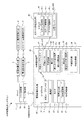
図1は、第1実施形態の中継自動改札システム1のブロック図である。
中継自動改札システム1は、鉄道等の入退場ゲートに用いられる改札システムである。中継自動改札システム1は、サーバ2及び複数の電磁誘導改札機3が接続された従来のシステムに、中継改札機10がサーバ2に接続されて構成される。中継自動改札システム1で用いられる切符、定期券等は、ICチップが内蔵されたICカード4,40(情報記憶媒体)である。
サーバ2は、サーバ記憶部2a、サーバ制御部2bを備える。
サーバ記憶部2aは、サーバ2の動作に必要なプログラム、情報等を記憶するハードディスク、半導体メモリ素子等の記憶装置である。
サーバ記憶部2aは、例えば、ICカード4,40の情報(乗車区間、期限、利用者の氏名等)を記憶する。サーバ記憶部2aの情報は、券売機等でICカード4,40が再発行される場合等に適宜参照される。
サーバ制御部2bは、サーバ2を統括的に制御するための制御部であり、例えばCPU等から構成される。サーバ制御部2bは、サーバ記憶部2aに記憶された各種プログラムを適宜読み出して実行する。
電磁誘導改札機3は、従来の電磁誘導方式の改札機であり、電磁誘導方式のICカード4との間で、情報の送受信をすることができる。
(First embodiment)
Hereinafter, a first embodiment of the present invention will be described with reference to the drawings and the like.
FIG. 1 is a block diagram of a relay automatic
The relay automatic
The
The
The
The
The electromagnetic
中継改札機10は、従来の電磁誘導改札機20(電磁誘導通信装置)に対して、中継通信装置30が加えられることにより構成される。中継改札機10は、中継通信装置30を介して、電磁誘導改札機20及び静電結合(静電容量結合)型のICカード40との間で情報を送受信できる。
なお、中継自動改札システム1は、電磁誘導改札機3を利用せずに、複数の中継改札機10のみから構成してもよい。また中継改札機10は、従来の電磁誘導改札機20及び中継改札機10を組み合わせた装置ではなく、新たに専用に設けた一体型の装置でもよい。
The
Note that the relay automatic
以下、中継改札機10の構成について詳細に説明する。
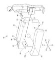
図2は、第1実施形態の中継改札機10の斜視図である。
図3は、第1実施形態のリーダライタ21近傍の分解斜視図と、電磁誘導改札機20、中継通信装置30及びICカード40の間の通信を説明する断面図である。
図3(a)は、リーダライタ21近傍の分解斜視図であり、図3(b)は、電磁誘導改札機20、中継通信装置30及びICカード40の間の通信を説明する模式的な断面図(図3のB−B部矢視断面図)である。
なお、以下の説明において、図2に示すように、利用者が中継改札機10の入口10aから出口10bに進行する場合の利用者の左右方向をX、鉛直方向Zとする。利用者の進行方向は、ICカード40の搬送方向Yと一致している。また、鉛直方向Zの上側Z2から見た図を、適宜平面図といい、その形状を平面形状という。
Hereinafter, the configuration of the
FIG. 2 is a perspective view of the
FIG. 3 is an exploded perspective view in the vicinity of the reader /
3A is an exploded perspective view of the vicinity of the reader /
In the following description, as shown in FIG. 2, the left-right direction of the user when traveling from the
中継改札機10は、鉄道の各駅に配置される装置である。中継改札機10は、利用者が所持するICカード40の情報を読み取り、乗車区間、使用期間等の認証を行い、通過扉22の開閉等を行う。
中継改札機10は、従来の電磁誘導改札機20と、電磁誘導改札機20に載置された中継通信装置30とを備える。図2では、中継改札機10の手前側から奥側に向かって歩行するようになっている。実施形態では、利用者の入場、出場に関わらず、手前側を入口10a、奥側を出口10bとして説明する。
The
The
電磁誘導改札機20は、本来は、電磁誘導方式のICカード4との間で、情報を送受信可能な、電磁誘導改札機3と同様な装置であるが、実施形態では、中継通信装置30を介して、電磁誘導方式のICカード40との間で情報を送受信できる。
図2、図3に示すように、電磁誘導改札機20は、リーダライタ21、通過扉22、モニタ23、音声出力部24を備える。
図3に示すように、リーダライタ21は、改札ループアンテナ21a(電磁誘導通信装置側ループアンテナ)を備える。
改札ループアンテナ21aは、例えば、3回巻き程度のループアンテナであり、大きさが40mm×40mm程度である。改札ループアンテナ21aは、エッチング等の手法により、プリント配線基板上に銅線を配線して形成される。
The electromagnetic
As shown in FIGS. 2 and 3, the electromagnetic
As shown in FIG. 3, the reader /
The ticket
図2に示すように、通過扉22は、電磁誘導改札機20の筐体に設けられた開閉扉である。通過扉22は、DCモータ等を備える駆動装置によって開閉駆動される。
モニタ23及び音声出力部24は、通信処理の結果を報知する報知部である。
モニタ23は、液晶表示装置等の表示装置である。モニタ23は、電磁誘導改札機20のケース表面のうち搬送方向Y下流側の範囲に配置されている。モニタ23は、例えば文字等を出力して、残高、通信異常等を報知する。なお、利用者がモニタ23を目視できるように、中継通信装置30は、モニタ23が露出するように、電磁誘導改札機20上に載置されている。
音声出力部24は、音声出力するスピーカである。音声出力部24は、例えば、警告音、音声ガイド等を出力して、通信異常等を報知する。
As shown in FIG. 2, the passing
The
The
The
図1から図3に示すように、中継通信装置30は、電磁誘導改札機20上に載置されることにより、電磁誘導改札機20及びICカード40間の通信を可能にする装置である。中継通信装置30は、中継ループアンテナ31、一対の導電レール32L,32R、搬送装置33、挿入口34、排出口35を備える。
図3に示すように、中継ループアンテナ31は、改札ループアンテナ21aとの間で電磁誘導方式により通信(結合)するアンテナである。中継ループアンテナ31は、例えば、3回巻き程度のループアンテナであり、大きさが40mm×40mm程度である。中継ループアンテナ31は、エッチング等の手法により、プリント配線基板上に銅線を配線して形成される。
As shown in FIGS. 1 to 3, the
As shown in FIG. 3, the
導電レール32L,32Rは、樹脂等の絶縁性材料に形成されたレール基材32aに、例えば、長さL1=1mmの間隔を隔てて、レール状に貼り付けられている。導電レール32L,32Rは、ICカード40の搬送方向Yに沿って平行に配置されている。なお、本発明でレールとは、情報記憶媒体を一定方向に搬送するために敷かれた細長いプレート、又は平面形状が長四角形状のプレートをいう。
導電レール32L,32Rは、銅箔等の導電性を有する材料により形成される。導電レール32L,32Rは、それぞれ、厚さ35μm、幅40mm、長さ600mmの細長い形状である。各導電レール32L,32Rは、それぞれ中継ループアンテナ31の両端に電線32bにより電気的に接続されている。
後述するように、カード搬送時において、導電レール32L,32Rは、ICカード40の一対の導電プレート42L,42R(後述する)にほぼ密着し(例えば、導電レール32L,32Rの上面と、導電プレート42L,42Rの下面との距離L3=2mm程度)、かつ、この導電プレート42L,42Rにそれぞれ対向配置される。このため、導電レール32L,32Rは、カード搬送時において、ICカード40の導電プレート42L,42Rと静電結合する。
The
The
As will be described later, when the card is transported, the
搬送装置33は、ICカード40を導電レール32L,32R上を搬送方向Yに搬送する装置である。搬送装置33の詳細は、後述する。
図2に示すように、挿入口34は、利用者がICカード40を挿入するための入口である。挿入口34には、挿入カード送り装置34a、挿入口開閉扉34b(図1参照)が設けられている。
挿入カード送り装置34aは、ローラ及びこれを回転するモータ等を備え、挿入されたICカード40を搬送装置33に導く装置である。
挿入口開閉扉34bは、挿入口34を開閉する扉及びこれを開閉駆動するモータ等を備える装置である。
The
As shown in FIG. 2, the
The insertion
The insertion port opening /
排出口35は、搬送装置33によって搬送されたICカード40を排出する出口である。排出口35は、排出カード送り装置35a(図1参照)が設けられている。
排出カード送り装置35aは、ローラ及びこれを回転するモータ等を備え、搬送装置33によって搬送されたICカード40を、排出口35に導く装置である。
The
The discharge card feeding device 35 a is a device that includes a roller and a motor that rotates the roller, and guides the
図3に示すように、ICカード40は、外部接触端子を備えない非接触型のICカード40である。ICカード40は、ICチップ41、一対の導電プレート42L,42R(導電性板部材)、下層43、上層44を備える。
ICチップ41は、電磁誘導方式で通信可能な集積回路であり、従来のアンテナを具備する電磁誘導方式のICカード4(図1参照)に内蔵されているものと、同種のものである。ICチップ41は、厚さが例えば150μm程度である。ICチップ41は、導電プレート42L,42Rを跨ぐように配置されている。
ICチップ41の入出力部(リードフレーム等)は、導電プレート42L,42Rに対して、異方性導電性ペースト、異方性導電性フィルム、導電性接着剤等の接続部材46によって、それぞれ電気的及び機械的に接続されている。ICチップ41が電磁誘導方式であるので、この入出力部は、本来、ループアンテナに接続されるものである。ICチップ41は、この入出力部を導電プレート42L,42Rに接続することにより、後述するように、中継通信装置30を介して、電磁誘導改札機20との間で通信できる。
As shown in FIG. 3, the
The
The input / output unit (lead frame or the like) of the
導電プレート42L,42Rは、それぞれ厚さ10μm、短辺×長辺が10mm×50mmのアルミ箔である。導電プレート42L,42Rは、短手方向(搬送方向Yとは直交する方向)に並べて配置され、下層43に貼り付けられている。導電プレート42L,42Rとの間隔L2は、例えば0.5mm程度である。
下層43は、例えば、厚さ180μm、短辺×長辺が25.0mm×57.5mmのPET、PET−G、PVC、ポリイミド等の絶縁性フィルム基材である。
上層44は、厚さ200μmの紙、樹脂等である。上層44は、ICチップ41、導電プレート42L,42Rを覆うように、粘着剤45等によって下層43に貼り付けられている。
The
The
The
中継通信装置30を介した、電磁誘導改札機20及びICカード40の間通信について説明する。
改札ループアンテナ21a及び中継ループアンテナ31の間は、電磁誘導方式により非接触で接続され、情報の送受信をすることができる。電磁誘導方式を用いたICカード40の通信方式は、ISO/IEC14443,15693,18092にて規格化されており、13.56MHzの信号周波数が用いられる。改札ループアンテナ21a及び中継ループアンテナ31の間の通信方式も、これに準ずる。
なお、改札ループアンテナ21a及び中継ループアンテナ31の巻数は、3巻程度である例を説明したが、これに限定されない。両者の間が電磁誘導方式により非接触で接続される巻数であればよく、巻数は、例えば1巻以上であればよい。
Communication between the electromagnetic
The ticket
In addition, although the number of turns of the ticket
一方、導電レール32L,32R及び導電プレート42L,42Rは、コンデンサプレートとして機能して、両者の間が静電結合方式により非接触で接続され、情報の送受信をすることができる。
On the other hand, the
中継改札機10は、中継ループアンテナ31が改札ループアンテナ21aに電磁誘導により発生した起電力によって、導電レール32L,32R及び導電プレート42L,42Rが静電結合し、ICチップ41に駆動電力が伝達される。また、電磁誘導改札機20からの送信データをICチップ41に伝達でき、一方、ICチップ41からの返信データを中継通信装置30を介して、電磁誘導改札機20に伝達できる。
In the
搬送装置33について説明する。
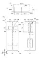
図4は、第1実施形態の搬送装置33を説明する平面図、及び断面図である。
図4(a)は、導電レール32L,32Rに配置された下ローラ33aを説明する平面図である。
図4(b)は、下ローラ33a及び上ローラ33bを説明する断面図(図4(a)のB−B部矢視断面図)である。
搬送装置33は、複数の下ローラ33a、上ローラ33bを備える。
下ローラ33a、上ローラ33bは、静電結合に影響を与えないように、ゴム等の絶縁材によって形成される。下ローラ33a、上ローラ33bは、それぞれ回転軸の方向が、左右方向Xになるように配置される。
下ローラ33aは、導電レール32L,32Rに部分的に設けられた開口部32cに配置され、ICカード40の搬送方向Yに配列されている。この開口部32cは、下ローラ33aが回転可能であればよいので、下ローラ33aの平面形状よりも、少し大きい程度である。下ローラ33aは、外周面の一部が、導電レール32L,32Rの表面から突出するように配置される。この突出量は、導電レール32L,32Rの表面と、ICカード40の導電プレート42L,42Rとの間の距離L3が、前述したように、例えば約2mm程度になるように、設定されている。下ローラ33aは、DCモータ等(図示せず)によって、搬送方向Yの下流側Y2に対応した方向(図4(b)に示す右回り)に回転駆動される。
The
4A and 4B are a plan view and a cross-sectional view illustrating the
FIG. 4A is a plan view illustrating the
FIG. 4B is a sectional view for explaining the
The
The
The
各上ローラ33bは、平面図において、各下ローラ33aに対応した位置に配置され、鉛直方向Zにおいて、各下ローラ33aとの間にICカード40を挟み込める程度の隙間を有するように配置される。各上ローラ33bは、中継通信装置30内に回転可能に支持される。
Each
搬送装置33は、ICカード40の長手方向が搬送方向Yになるように、かつカード表が鉛直方向を向くように、ICカード40を搬送する。これにより、導電プレート42L,42Rは、左右方向X(搬送方向Yに直交する方向)に並べて配列され、導電プレート42L,42Rの長辺方向は、ICカード40の搬送方向Yに一致する。
これにより、搬送装置33は、導電レール32L,32R上の上流側Y1から下流側Y2に至るまで、導電プレート42L,42Rと導電レール32L,32Rとを常に対向配置できる。このため、中継改札機10は、ICカード40を搬送させながら通信処理を行うことができる。
なお、後述するように、導電レール32L,32R上の下流側Y2の範囲は、通信結果を判定するために、搬送装置33が搬送しているICカード40を停止する停止範囲A1(通信結果判定範囲)である。
The
Thereby, the conveying
As will be described later, the downstream Y2 range on the
図5は、導電レールと導電プレートとが対向する面積を説明する平面図である。
図5(a)は、実施形態の下ローラ33aの配置を説明する平面図である。
図5(b)は、下ローラ33a−2を導電レール32L−2,32R−2間の中心線に沿って配列し、導電レール32L−2,32R−2間の間隔を大きくした例である。
図5(c)は、下ローラ33a−3を導電レール32L−3,32R−3の外側に配置し、導電レール32L,32Rの幅を小さくした例である。
図5(b)、図5(c)の場合には、実施形態の図5(a)の場合よりも、導電レール32L,32Rと導電プレート42L,42Rとが対向する面積が小さくなってしまう。
つまり、図5(a)のように、下ローラ33aを導電レール32L,32Rに部分的に設けられた開口部32cに配置することにより、導電レール32L,32Rの表面積の減少を少なくできる。これにより、搬送装置33は、導電レール32L,32Rと導電プレート42L,42Rとが対向する面積を広くでき、通信安定性を向上できる。
FIG. 5 is a plan view for explaining an area where the conductive rail and the conductive plate face each other.
FIG. 5A is a plan view for explaining the arrangement of the
FIG. 5B is an example in which the
FIG. 5C illustrates an example in which the
In the case of FIG. 5B and FIG. 5C, the area where the
That is, as shown in FIG. 5A, the
図1を参照して、中継改札機10、ICカード40のブロック図について説明する。
電磁誘導改札機20は、改札機記憶部26、改札制御部27(通信結果判定制御部)を備える。
改札機記憶部26は、電磁誘導改札機20の動作に必要なプログラム、情報等を記憶するための半導体メモリ素子等の記憶装置である。
改札制御部27は、電磁誘導改札機20を統括的に制御するための制御部であり、例えばCPU等から構成される。改札制御部27は、改札機記憶部26に記憶された各種プログラムを適宜読み出して実行することにより、前述したハードウェアと協働し、本発明に係る各種機能を実現している。
なお、電磁誘導改札機20は、電磁誘導改札機3と同様な構成であるので、改札機記憶部26、改札制御部27は、電磁誘導改札機3に設けられている記憶部、制御部(図示せず)と、基本的な構成が同様である。
A block diagram of the
The electromagnetic
The ticket
The ticket
Since the electromagnetic
中継通信装置30は、中継記憶部36、中継制御部37を備える。
中継制御部37は、中継通信装置30の動作に必要なプログラム、情報等を記憶するための半導体メモリ素子等の記憶装置である。
中継制御部37は、中継通信装置30を統括的に制御するための制御部であり、例えばCPU等から構成される。中継制御部37は、中継記憶部36に記憶された各種プログラムを適宜読み出して実行することにより、前述したハードウェアと協働し、本発明に係る各種機能を実現している。
中継制御部37は、電磁誘導改札機20に電気的に接続されており、電磁誘導改札機20及びICカード40間での通信の結果、判定及び状況を確認できる。
The
The
The
The
ICカード40のICチップ41は、ICチップ記憶部41a、ICチップ制御部41b、アナログ回路部41cを備える。
ICチップ記憶部41aは、ICカード40の動作に必要なプログラム、情報等を記憶するための記憶回路である。ICチップ記憶部41aは、例えば、乗車区間、使用期間、利用者の氏名等の情報を、書き換え可能に記憶する。
ICチップ制御部41bは、ICカード40を統括的に制御するための制御部であり、例えばCPU等から構成される。ICチップ制御部41bは、ICチップ記憶部41aに記憶された各種プログラムを適宜読み出して実行することにより、本発明に係る各種機能を実現している。
アナログ回路部41cは、整流回路、変調回路、復調回路、CLK抽出回路により構成されており、ICチップ入出力端子を介して入力された信号よりAD変換、クロック生成を行い、ICチップ制御部41bへの電圧供給、クロック供給、データ入出力を行う。
The
The IC
The IC
The
次に、実施形態の中継改札機10の動作について説明する。
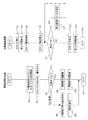
図6は、第1実施形態の中継改札機10の動作のフローチャートである。
(ICカード挿入処理)
S1において、図1,図2に示すように、利用者が入口10aでICカード40を挿入口34に挿入すると、挿入口34の光学センサ等の検出部(図示せず)は、挿入されたICカード40を検出し、検出情報を中継制御部37に出力する。中継制御部37は、この検出部の出力に応じて、挿入カード送り装置34aを駆動して、挿入されたICカード40を搬送装置33へと導く。
S2において、中継制御部37は、挿入口34の検出部の出力に基づいて、挿入口34から他のICカード40が挿入できないように、挿入口開閉扉34bを閉駆動する。挿入口開閉扉34bを閉駆動する理由は、ICカード40の通信処理中に他のICカード40が挿入されと、リーダライタ21がいずれのICカード40と通信しているのかの判別が困難になり、通信処理の異常発生要因となるためである。
なお、利用者は、入口10aから出口10bに向けて歩行を続ける。
Next, operation | movement of the
FIG. 6 is a flowchart of the operation of the
(IC card insertion processing)
In S1, as shown in FIGS. 1 and 2, when the user inserts the
In S <b> 2, the
Note that the user continues walking from the
(カード搬送処理)
S3において、導電レール32L,32Rの上流の光学センサ等の検出部(図示せず)は、挿入カード送り装置34aによって導かれたICカード40を検出すると、検出情報を中継制御部37に出力する。中継制御部37は、この検出部の出力に基づいて、搬送装置33を駆動してICカード40の搬送を開始する。
(通信処理)
S4において、ICカード40が導電レール32L,32R上を搬送方向Yに搬送される間、改札ループアンテナ21aが中継ループアンテナ31に電磁誘導方式により接続され、導電レール32L,32RがICカード40の導電プレート42L,42Rに静電結合する。
これにより、改札制御部27は、導電レール32L,32R上を移動しているICカード40のICチップ41との間で情報の送受信を開始する。
S5において、改札制御部27は、通信処理として、ICチップ41の情報を読み出し、書き込みを開始する。例えば、改札制御部27は、ICチップ41の情報を読み出して乗車区間等が適切であるかの認証や、利用者の改札からの出入に関する情報のICチップ41への書き込みを行う。
(Card transport processing)
In S3, when a detection unit (not shown) such as an optical sensor upstream of the
(Communication processing)
In S4, while the
Thereby, the ticket
In S5, the ticket
(搬送停止処理)
S6において、ICカード40が、導電レール32L,32R上の下流側Y2の停止範囲A1(図4参照)に搬送されると、停止範囲A1に配置された光学センサ等の検出部は、搬送されたICカード40を検出して、検出情報を中継制御部37に出力する。中継制御部37は、この検出部の出力に基づいて、搬送装置33を駆動停止して、停止範囲A1にICカード40を滞留させる。
(Transfer stop processing)
In S6, when the
(通信終了判定処理)
S7において、中継制御部37は、改札制御部27及びICチップ41の間の送受信の監視内容に基づいて、改札制御部27及びICチップ41の間で通信中であるか否かを判定する。中継制御部37は、改札制御部27及びICチップ41の間で通信中であると判定した場合には(S7:YES)、S71に進み、一方、通信が終了したと判定した場合には(S7:NO)、S12に進む。
S71において、中継制御部37は、停止範囲A1にICカード40を滞留させた状態を維持し、S7からの処理を繰り返す。これにより、中継制御部37は、通信が終了するまで(S7:NO)、ICカード40を停止範囲A1に滞留する。
これにより、中継制御部37は、通信処理時間と搬送スピードとを合わせる必要がなくなるので、搬送装置33の制御を容易にできる。
また、中継自動改札システム1は、通信処理遅延にともなう異常発生を低減できる。その理由は、以下の通りである。
例えば、「搬送に要する時間>通信に要する時間(リトライなし)」となるように搬送スピードを設定したとしても、通信異常が発生し、リトライ処理が行われた場合、「搬送に要する時間<通信処理に要する時間(リトライ処理含む)」となり、搬送完了時に通信処理が完了せずに、通信異常と判定されてしまうおそれがある。これに対して、中継自動改札システム1は、中継制御部37が、通信が終了するまで、停止範囲A1にICカード40を滞留させた状態を維持するので、リトライ等による通信処理遅延にともなう異常発生を低減できる。
(Communication end determination process)
In S <b> 7, the
In S71, the
As a result, the
Further, the relay automatic
For example, even if the transport speed is set so that “time required for transport> time required for communication (no retry)”, if a communication error occurs and retry processing is performed, “time required for transport <communication The time required for the process (including retry process) ”is reached, and the communication process may not be completed when the transfer is completed, and the communication may be determined to be abnormal. On the other hand, since the relay automatic
S8において、改札制御部27は、ICチップ41との間の送受信の内容に基づいて、乗車期間の情報等が適切であるか否か、つまり通信処理の結果が正常であるか否を判定する。
改札制御部27は、通信処理の結果が正常である判定した場合には(S8:YES)、S9に進み、一方、通信処理の結果が異常であると判定した場合には(S8:NO)、S81に進む。
In S8, the ticket
When it is determined that the result of the communication process is normal (S8: YES), the ticket
(通過扉開閉処理)
S9において、改札制御部27は、通過扉22を開駆動する。
S10において、光学センサ等の検出部は、出口10bに向かって利用者が改札機を通過したことを検出すると、改札制御部27は、この検出部の出力に基づいて、通過扉22を閉駆動したり、又は、一定時間経過の後、通過扉22を閉駆動し、そして、電磁誘導改札機20側の処理を終了し、次のICカード40の受付を開始する(S11)。
(異常報知処理)
S81において、改札制御部27は、通過扉22の閉状態を維持して、S82において、音声出力部24か警告音を出力し、また表示部にICカード40が不適切である旨の表示をして、利用者に通信処理の結果が異常であることを報知する。そして、電磁誘導改札機20側の処理を終了し、次のICカード40の受付を開始する(S11)。
(Passing door opening / closing process)
In S9, the ticket
In S10, when the detection unit such as an optical sensor detects that the user has passed the ticket gate toward the
(Abnormality notification processing)
In S81, the ticket
(カード排出処理)
S12において、中継制御部37は、排出搬送機構を駆動して、停止範囲A1に搬送されたICカード40を排出口35から排出する。
なお、ICカード40が切符等の一回券である場合のために、出場時においては、ICカード40を収容する収容装置を設けてもよい。この場合には、中継制御部37(通信結果判定制御部)が改札制御部27及びICチップ41の間の送受信の監視内容に基づいて、改札制御部27及びICチップ41の間の通信処理が正常に終了したか否かを判定すればよい。そして、中継制御部37は、正常に終了したと判定した場合には、収容装置を制御して、ICカード40を収容容器内に収容し、一方、異常があったと判定した場合には、ICカード40を排出すればよい。
(Card discharge processing)
In S12, the
In addition, since the
(挿入口開駆動処理)
S13において、排出口35に設けられた光学センサ等の検出部(図示せず)は、排出口35から排出されたICカード40を利用者が抜き取ったことを検出すると、検出情報を中継制御部37に出力する。中継制御部37は、この検出部の出力に基づいて、挿入口開閉扉34bを開駆動して、中継通信装置30側の処理を終了し、次のICカード40の受付を開始する(S14)。
これにより、ICカード40の通信処理が正常に終了し通過扉22の挿入口開閉扉34bが開駆動が完了するまで(S10)、又は通信処理が異常であった場合に復旧処理が完了するまで、挿入口34への他のICカード40の挿入防止をすることができる。
(Insertion opening drive processing)
In S13, when a detection unit (not shown) such as an optical sensor provided in the
Thereby, until the communication process of the
以上の処理によって、利用者は、通信結果が正常である場合には(S8:YES)、排出口35から排出されたICカード40(S12)を抜き取って、開駆動された通過扉22を通って出口10bから中継改札機10を通過できる。
一方、利用者は、通信結果が異常である場合には(S8:NO)、通過扉22が閉位置を維持されているので(S81)、中継改札機10を通過できず、入口10aに戻って排出口35から排出されたICカード40(S12)を抜き取って、再度挿入口34に挿入したり、ICカード40が不適切であることを認識して、清算処理等を行うことができる。
Through the above processing, when the communication result is normal (S8: YES), the user pulls out the IC card 40 (S12) discharged from the
On the other hand, when the communication result is abnormal (S8: NO), since the passing
また、ICカード40の導電レール32L,32Rがレール状に設けられているので、ICカード40を搬送させる場合に、導電レール32L,32RとICカード40の導電プレート42L,42Rとが近接して対向した状態を維持できる。これにより、利用者が中継改札機10内を歩行する時間を利用して、ICカード40を搬送させながら通信処理できるため、ゲートアクセス処理時間等を短縮できる。
Further, since the
例えば、従来の電磁誘導式の通信システムは、ICカード4とリーダライタとが数十mm程度多少離れていても通信できるため、ICカード4をリーダライタに近づけている途中から通信が可能となる。
これに対して、静電結合方式の通信システムのICカード40及びリーダライタ21間の通信距離は、前述したように2mm程度であり、電磁誘導方式の通信システムと比較すると短い。このため、ICカード40をリーダライタ21にほぼ密着させないと通信が開始されない。そのため、ICカード40及びリーダライタ21の間の通信時間は、電磁誘導方式の通信システムと同等であっても、利用者が体感する処理時間は、ICカード40を2mm程度まで近づける時間の分、長くなる。
実施形態の中継改札機10は、前述したように、利用者が入口10aから出口10bに向かって歩行する時間を利用して、ICカード40を通信処理して、利用者が体感する処理時間の短縮を図っている。これにより、中継改札機10は、静電結合方式を利用しても、利用者の通過時の混雑を抑制できる。
For example, a conventional electromagnetic induction type communication system can communicate even if the IC card 4 and the reader / writer are somewhat apart from each other by several tens of millimeters, and therefore communication can be performed while the IC card 4 is approaching the reader / writer. .
On the other hand, the communication distance between the
As described above, the
例えば、従来の搬送装置を有する電磁誘導方式の通信システムは、ICカードを通信可能領域まで搬送する時間が「搬送時間2秒」、停止させた後、通信処理をする時間が「通信処理時間1秒」であり、計3秒を要していた。これに対して、実施形態の中継改札機10は、ICカード40を搬送させながら通信処理を行うので、「搬送時間2秒」内で通信処理を終了させる。このため、処理時間を従来よりも1秒短縮できる。
For example, in an electromagnetic induction communication system having a conventional transport device, the time for transporting an IC card to a communicable area is “
以上説明したように、中継自動改札システム1は、改札ループアンテナ21aと中継ループアンテナ31とが電磁誘導することにより信号が伝達し、中継通信装置30の導電レール32L,32RとICカード40の導電プレート42L,42Rとを向かい合わせ、静電結合させることにより信号を伝達できる。
また、中継自動改札システム1は、ICカード40にループアンテナを形成する必要がなく、2つの導電プレート42L,42Rを設ければよいので、従来の複雑なエッチング等のアンテナ形成工程が不要となり、低コストでICカード40を製造できる。このため、ICカード40の発行枚数が多くなる程、コスト面で有利になり、低コストでシステムを構築できる。
As described above, in the automatic relay
In addition, the relay automatic
さらに、中継自動改札システム1は、市場で多く流通しているサーバ2及び電磁誘導システムの電磁誘導改札機3を用いるので、既存の電磁誘導システムに対して、中継改札機10を付加すれば、容易かつ低コストでシステムを構築できる。
さらにまた、新たなシステムを導入する場合であっても、電磁誘導方式のICカード40に用いられるICチップ41を流用でき、かつ、既存の非接触IC用のリーダライタ21を流用できる。これにより、静電結合用の特殊なICチップ41と、電磁誘導改札機20とを開発する必要なく、システムを構築できる。
Furthermore, since the automatic relay
Furthermore, even when a new system is introduced, the
(第2実施形態)
次に、本発明の第2実施形態について説明する。
なお、以下の説明及び図面において、前述した第1実施形態と同様の機能を果たす部分には、同一の符号又は末尾に同一の符号を付して、重複する説明を適宜省略する。
図7は、第2実施形態のICカード240の平面図、及びICカード240のずれを説明する平面図である。
図7(a)に示すように、ICカード240は、導電プレート242L,242Rは、ICカード240の長手方向に沿って並べて配置されている。
例えば、ICカード240の外形は、長辺×短辺が、57.5mm×25mmであり、また導電プレート242L,242Rの外形は、長辺×短辺が、25mm×20mmである。
(Second Embodiment)
Next, a second embodiment of the present invention will be described.
Note that, in the following description and drawings, the same reference numerals or the same reference numerals are given to the portions that perform the same functions as those in the first embodiment described above, and overlapping descriptions will be omitted as appropriate.
FIG. 7 is a plan view of the
As shown in FIG. 7A, in the
For example, the outer shape of the
図7(b)に示すように、中継通信装置230の搬送装置233は、搬送方向Yと、導電プレート242L,242Rの長辺242aが直交するように、ICカード240を搬送する。
これにより、ICカード240が左右方向X(搬送方向Yとは直交する方向(長辺方向))にずれても、ICカード240の導電プレート242L,242Rと中継通信装置230の導電レール232L,232Rとが対向する面積の減少率が少なくなるため、位置ずれの許容度を向上でき、通信安定性を向上できる。
As shown in FIG. 7B, the
Thereby, even if the
ずれにともなう面積の減少率が少なることについて説明する。
図7(c)のICカード340は、導電プレート342L,342Rが、ICカード340の長手方向に細長く、短辺342bの方向に並べて配置されたものである。平面形状において、ICカード240の面積は、ICカード340の面積に等しい。このため、各導電プレートの搬送方向Yの長さは、「L20<L30」である。
例えば、図7(b)、図7(c)に示すように、ICカード240及びICカード340が左右方向Xに長さΔ分ずれた場合を考える。ICカード240の場合は、導電プレート242L,242Rと導電レールとが対向する面積は、「Δ×L20」減少し、一方、ICカード340は、「Δ×L30」減少する。「L20<30」であるため、「Δ×L20<Δ×L30」が成り立つ。
The fact that the area reduction rate due to the shift is small will be described.
In the
For example, consider a case where the
このように、ICカード240は、ずれにともなう面積減少量がICカード340よりも少なく、通信安定性を向上できる。
なお、ICカード240、ICカード340が搬送方向Yにずれた場合は、いずれの場合も面積減少はなく、同等の通信安定性を保つことができる。
As described above, the
When the
図8は、第2実施形態の搬送装置233、挿入口234、排出口235を模式的に示す平面図である。
挿入口234、排出口235の内部には、それぞれ、ICカード整列装置234c,235cを備える。
挿入口234のICカード整列装置234cは、長手方向が搬送方向Yになるように、ICカード240が挿入口234に挿入された場合に、ICカード240が挿入カード送り装置234aによって搬送装置233に導かれる途中で、ICカード240をその長手方向(つまり一対の導電プレート242L,242Rが並べられた方向)が左右方向X(搬送方向Yとは直交する方向)になるように、回転させて整列させる装置である。ICカード整列装置234cは、突出したり、引き込んだりする突起234dを備えており、これらを駆動して、ICカード240を整列させる。なお、ICカード整列装置234cの構成は、これに限らず、搬送するカードを回転する他の公知技術を用いることができる。
FIG. 8 is a plan view schematically showing the
IC
When the
中継改札機210は、上記構成により、導電レール232L,232Rと導電プレート242L,242Rとが対向配置されるように、ICカード240を搬送装置233に導くことができ、また長手方向に細長いICカード240であっても、挿入口234に挿入しやすい。
With the above configuration, the
排出口235のICカード整列装置235cは、搬送装置233によって長手方向が左右方向Xになる状態で搬送されたICカード240を、排出カード送り装置235aによって排出口235に導かれる途中で、長手方向が搬送方向Yになるように回転させて整列させる装置である。ICカード整列装置235cの構成は、ICカード整列装置234cと同様な構成である。
The IC
なお、利用者がICカード240を挿入口234に挿入する場合に、長手方向が左右方向Xになるように挿入する仕様であっても、利用者が多少回転させて挿入してしまうときがある。この場合であっても、ICカード整列装置234cと同様な装置を設けることにより、ICカード240を整列し、通信安定性を向上できる。なお、このようなICカード整列装置234c,235cは、第1実施形態の中継改札機10に設けてもよい。
Note that when the user inserts the
以上説明したように、本実施形態の中継改札機210は、長手方向に細長いICカード240であっても、ICカード240を挿入口234に挿入しやすく、また排出口235から取り出しやすく、操作性を向上できる。
As described above, the
以上、本発明の実施形態について説明したが、本発明は前述した実施形態に限定されるものではなく、後述する変形形態のように種々の変形や変更が可能であって、それらも本発明の技術的範囲内である。また、実施形態に記載した効果は、本発明から生じる最も好適な効果を列挙したに過ぎず、本発明による効果は、実施形態に記載したものに限定されない。なお、前述した実施形態及び後述する変形形態は、適宜組み合わせて用いることもできるが、詳細な説明は省略する。 Although the embodiments of the present invention have been described above, the present invention is not limited to the above-described embodiments, and various modifications and changes can be made as in the modifications described later, and these are also included in the present invention. Within the technical scope. In addition, the effects described in the embodiments are merely a list of the most preferable effects resulting from the present invention, and the effects of the present invention are not limited to those described in the embodiments. It should be noted that the above-described embodiment and modifications described later can be used in appropriate combination, but detailed description thereof is omitted.
(変形形態)
(1)実施形態において、リーダライタ及び中継通信装置は、電磁誘導方式により通信する例を示したが、これに限定されない。例えば、リーダライタ及び中継通信装置は、電磁結合方式によって通信してもよい。この場合には、ICカードに設けるICチップを、電磁結合方式によって通信できるタイプにすればよい。
なお、電磁結合は、原理的には電磁誘導と同じである。また、電磁結合方式の通信とは、カード側のアンテナとリーダライタ側のアンテナを対向させ、静止状態で電磁誘導により通信することをいう。
(Deformation)
(1) In the embodiment, the reader / writer and the relay communication device have shown an example in which communication is performed by an electromagnetic induction method, but the present invention is not limited to this. For example, the reader / writer and the relay communication device may communicate by an electromagnetic coupling method. In this case, the IC chip provided in the IC card may be of a type that can communicate by electromagnetic coupling.
The electromagnetic coupling is in principle the same as electromagnetic induction. Further, the electromagnetic coupling type communication refers to communication by electromagnetic induction in a stationary state with the card side antenna and the reader / writer side antenna facing each other.
(2)実施形態において、中継通信装置は、プレート型の導電レールとICカードを搬送する搬送装置を備える例を示したが、導電レールを可動式のベルト形態とし、ICカードを前記ベルト上に乗せ、ベルトを駆動させることによりICカードを移動してもよい。 (2) In the embodiment, the relay communication device is provided with a plate-type conductive rail and a transport device that transports the IC card. However, the conductive rail is a movable belt, and the IC card is placed on the belt. The IC card may be moved by placing it and driving the belt.
(3)実施形態において、中継通信装置は、ICカードを搬送する搬送装置を備える例を示したが、これに限定されない。例えば、利用者が自ら導電レール上を、ICカードを搬送方向に滑らせながら移動してもよい。 (3) In the embodiment, an example in which the relay communication device includes a transport device that transports an IC card has been described, but the embodiment is not limited thereto. For example, the user may move on the conductive rail while sliding the IC card in the transport direction.
(4)実施形態において、通信異常を報知する報知部は、電磁誘導改札機に設けられた例を示したが、これに限定されない。報知部は、中継通信装置に設けてもよい。この場合には、中継制御部が、ICカードが停止範囲に搬送されたときに、監視する改札制御部及びICチップの間の送受信の内容に基づいて、通信異常であるか否かを判定し、報知部を制御すればよい。 (4) In the embodiment, the notification unit that notifies the communication abnormality has been described as being provided in the electromagnetic induction ticket gate, but is not limited thereto. The notification unit may be provided in the relay communication device. In this case, when the IC card is transported to the stop range, the relay control unit determines whether there is a communication abnormality based on the contents of transmission / reception between the ticket gate control unit to be monitored and the IC chip. What is necessary is just to control an alerting | reporting part.
(5)実施形態において、中継通信装置は、中継ループアンテナ、導電レール、搬送装置等が一体で1つの筐体内に組み込まれている例を示したが、これに限定されない。これらが一体として機能するシステムであれば、別々の筐体内に設けられていてもよい。 (5) In the embodiment, the relay communication device is an example in which the relay loop antenna, the conductive rail, the transport device, and the like are integrally incorporated in one housing, but is not limited thereto. If these are systems that function as a unit, they may be provided in separate housings.
(6)実施形態において、中継通信装置は、鉄道の改札システムに設けられている例を示したが、これに限定されない。このシステムは、電子マネー、社員証システム、物流管理等の各種システム等の様々なシステムに適用できる。例えば、店舗等のレジスタシステムに、電子マネーに関する電磁誘導方式のリーダライタが設けられている場合には、実施形態と同様に、このリーダライタに対して通信する中継通信装置を設ければ、容易に従来のレジスタシステムの適用できるし、また新たなレジスタシステムであっても、低コストで導入できる。 (6) In the embodiment, the example in which the relay communication device is provided in the railway ticket gate system is shown, but the embodiment is not limited thereto. This system can be applied to various systems such as various systems such as electronic money, employee ID system, and logistics management. For example, when an electromagnetic induction reader / writer for electronic money is provided in a register system such as a store, it is easy to provide a relay communication device that communicates with the reader / writer as in the embodiment. In addition, a conventional register system can be applied, and even a new register system can be introduced at a low cost.
1…中継自動改札システム
10,210…中継改札機
20…電磁誘導改札機
21…リーダライタ
21a…改札ループアンテナ
30,230…中継通信装置
31…中継ループアンテナ
32L,32R…導電レール
33…搬送装置
33a…下ローラ
33b…上ローラ
37…中継制御部
40,240…ICカード
41…ICチップ
42L,42R,242L,242R…導電プレート
234…挿入口
234c,235c…ICカード整列装置
A1…停止範囲
DESCRIPTION OF
Claims (16)
前記情報記憶媒体は、
電磁誘導方式又は電磁結合方式で通信可能なICチップと、
前記ICチップに接続され、導電性を有する一対の導電プレートとを備え、
前記中継通信装置は、
中継ループアンテナと、
前記中継ループアンテナの両端に接続され、前記情報記憶媒体の搬送方向に沿ってレール状に設けられ、前記情報記憶媒体の前記一対の導電プレートと静電結合し、導電性を有する一対の導電レールとを備え、
前記電磁誘導通信装置は、
前記中継ループアンテナとの間で電磁誘導方式又は電磁結合方式により通信する通信装置側ループアンテナと、
前記通信装置側ループアンテナが前記中継通信装置との間で電磁誘導方式又は電磁結合方式により通信し、前記中継通信装置及び前記情報記憶媒体が静電結合することにより、前記情報記憶媒体の前記ICチップとの間で通信処理をする制御部とを備えること、
を特徴とする通信システム。 A communication system in which a relay communication device is interposed between an information storage medium and an electromagnetic induction communication device and communicates while conveying the information storage medium,
The information storage medium is
An IC chip capable of communicating by electromagnetic induction or electromagnetic coupling;
A pair of conductive plates connected to the IC chip and having conductivity;
The relay communication device is
A relay loop antenna,
A pair of conductive rails connected to both ends of the relay loop antenna, provided in a rail shape along the conveying direction of the information storage medium, electrostatically coupled to the pair of conductive plates of the information storage medium, and having conductivity And
The electromagnetic induction communication device is:
A communication device-side loop antenna that communicates with the relay loop antenna by an electromagnetic induction method or an electromagnetic coupling method;
The communication device-side loop antenna communicates with the relay communication device by an electromagnetic induction method or an electromagnetic coupling method, and the relay communication device and the information storage medium are electrostatically coupled, whereby the IC of the information storage medium A control unit that performs communication processing with the chip,
A communication system characterized by the above.
前記情報記憶媒体の前記一対の導電プレートは、搬送方向とは直交する方向に並べて配列されていること。
を特徴とする通信システム。 The communication system according to claim 1,
The pair of conductive plates of the information storage medium are arranged side by side in a direction perpendicular to the transport direction.
A communication system characterized by the above.
前記中継通信装置は、前記情報記憶媒体を搬送方向に搬送する搬送装置を備えること、
を特徴とする通信システム。 The communication system according to claim 1 or claim 2,
The relay communication device includes a transport device that transports the information storage medium in a transport direction;
A communication system characterized by the above.
前記中継通信装置は、
利用者が前記情報記憶媒体を挿入する挿入口と、
前記挿入口に挿入された前記情報記憶媒体を、前記一対の導電プレートが並べられた方向が、搬送方向とは直交する方向に整列する整列装置とを備えること、
を特徴とする通信システム。 In the communication system according to any one of claims 1 to 3,
The relay communication device is
An insertion slot into which the user inserts the information storage medium;
An alignment device that aligns the information storage medium inserted into the insertion slot in a direction in which the pair of conductive plates are arranged in a direction perpendicular to the transport direction;
A communication system characterized by the above.
前記導電プレートを有する前記情報記憶媒体は、長方形であり、前記一対の導電プレートが前記長方形の長辺に沿った方向に並べて配置され、
前記中継通信装置は、前記情報記憶媒体の搬送方向と前記情報記憶媒体の前記長方形の長辺とが、直交するように前記情報記憶媒体を搬送すること、
を特徴とする通信システム。 In the communication system according to any one of claims 1 to 4,
The information storage medium having the conductive plate is rectangular, and the pair of conductive plates are arranged in a direction along the long side of the rectangle,
The relay communication device transports the information storage medium such that a transport direction of the information storage medium and a long side of the rectangle of the information storage medium are orthogonal;
A communication system characterized by the above.
前記中継通信装置は、前記導電レールの表面に設けられた複数の開口部に配置され、前記情報記憶媒体の搬送方向に配列された複数のローラを備えること、
を特徴とする通信システム。 In the communication system according to any one of claims 1 to 5,
The relay communication device includes a plurality of rollers arranged in a plurality of openings provided on a surface of the conductive rail and arranged in a conveyance direction of the information storage medium;
A communication system characterized by the above.
前記中継通信装置は、前記一対の導電レール上に、通信処理の結果を判定する領域である通信結果判定範囲を有し、
前記電磁誘導通信装置又は前記中継通信装置に設けられ、通信処理の結果を報知する報知部と、
前記電磁誘導通信装置又は前記中継通信装置に設けられ、前記情報記憶媒体が前記通信結果判定範囲まで搬送された場合に、通信処理の結果を判定する通信結果判定制御部とを備え、
前記通信結果判定制御部は、
通信処理の結果が異常と判定した場合には、前記報知部を制御して異常発生を報知し、
通信処理中の場合には、通信処理が完了するまで通信処理を継続し、その結果が異常と判定した場合には、前記報知部を制御して異常発生を報知すること、
を特徴とする通信システム。 In the communication system according to any one of claims 1 to 6,
The relay communication device has a communication result determination range that is an area for determining a result of communication processing on the pair of conductive rails,
An informing unit provided in the electromagnetic induction communication device or the relay communication device and informing a result of communication processing;
A communication result determination control unit that is provided in the electromagnetic induction communication device or the relay communication device and determines a result of communication processing when the information storage medium is conveyed to the communication result determination range;
The communication result determination control unit
If it is determined that the communication processing result is abnormal, the notification unit is controlled to notify the occurrence of abnormality,
When the communication process is in progress, the communication process is continued until the communication process is completed, and when the result is determined to be abnormal, the notification unit is controlled to notify the occurrence of the abnormality.
A communication system characterized by the above.
前記電磁誘導通信装置の通信装置側ループアンテナとの間で、電磁誘導方式又は電磁結合方式により通信する中継ループアンテナと、
前記中継ループアンテナの両端に接続され、前記情報記憶媒体の搬送方向に沿ってレール状に設けられ、前記情報記憶媒体に設けられ電磁誘導方式又は電磁結合方式で通信可能なICチップに接続され導電性を有する一対の導電プレートとの間で静電結合して通信し、導電性を有する一対の導電レールとを備えること、
を特徴とする中継通信装置。 A relay communication device that is interposed between an information storage medium and an electromagnetic induction communication device provided in a communication system and communicates while conveying the information storage medium,
A relay loop antenna that communicates with the communication device side loop antenna of the electromagnetic induction communication device by an electromagnetic induction method or an electromagnetic coupling method;
Connected to both ends of the relay loop antenna, provided in a rail shape along the conveyance direction of the information storage medium, and connected to an IC chip that is provided on the information storage medium and can be communicated by electromagnetic induction or electromagnetic coupling. Having a pair of conductive rails that are electrostatically coupled to and communicate with a pair of conductive plates having electrical properties,
A relay communication device characterized by the above.
前記情報記憶媒体を搬送方向に搬送する搬送装置を備えること、
を特徴とする中継通信装置。 The relay communication device according to claim 8, wherein
A transport device that transports the information storage medium in the transport direction;
A relay communication device characterized by the above.
利用者が前記情報記憶媒体を挿入する挿入口と、
前記挿入口に挿入された前記情報記憶媒体を、前記一対の導電プレートが並べられた方向が、搬送方向とは直交する方向に整列する整列装置とを備えること、
を特徴とする中継通信装置。 In the relay communication device according to claim 8 or 9,
An insertion slot into which the user inserts the information storage medium;
An alignment device that aligns the information storage medium inserted into the insertion slot in a direction in which the pair of conductive plates are arranged in a direction perpendicular to the transport direction;
A relay communication device characterized by the above.
前記導電プレートを有する前記情報記憶媒体は、長方形であり、前記一対の導電プレートが前記長方形の長辺に沿った方向に並べて配置され、
前記情報記憶媒体の搬送方向と前記情報記憶媒体の長辺とが、直交するように前記情報記憶媒体を搬送すること、
を特徴とする中継通信装置。 In the relay communication device according to any one of claims 8 to 10,
The information storage medium having the conductive plate is rectangular, and the pair of conductive plates are arranged in a direction along the long side of the rectangle,
Transporting the information storage medium so that the transport direction of the information storage medium and the long side of the information storage medium are orthogonal to each other;
A relay communication device characterized by the above.
前記導電レールの表面に設けられた複数の開口部に配置され、前記情報記憶媒体の搬送方向に配列された複数のローラを備えること、
を特徴とする中継通信装置。 In the relay communication device according to any one of claims 8 to 11,
Comprising a plurality of rollers arranged in a plurality of openings provided on the surface of the conductive rail and arranged in the transport direction of the information storage medium;
A relay communication device characterized by the above.
前記一対の導電レール上に、通信処理の結果を判定する領域である通信結果判定範囲を有し、
前記電磁誘導通信装置又はこの中継通信装置は、
通信処理の結果を報知する報知部と、
前記情報記憶媒体が前記通信結果判定範囲まで搬送された場合に、通信処理の結果を判定する通信結果判定制御部とを備え、
前記通信結果判定制御部は、
通信処理の結果が異常と判定した場合には、前記報知部を制御して異常発生を報知し、
通信処理中の場合には、通信処理が完了するまで通信処理を継続し、その結果が異常と判定した場合には、前記報知部を制御して異常発生を報知すること、
を特徴とする中継通信装置。 In the relay communication device according to any one of claims 8 to 12,
On the pair of conductive rails, there is a communication result determination range that is an area for determining a result of communication processing,
The electromagnetic induction communication device or the relay communication device is
An informing unit for informing a result of the communication processing;
A communication result determination control unit that determines a result of communication processing when the information storage medium is transported to the communication result determination range;
The communication result determination control unit
If it is determined that the communication processing result is abnormal, the notification unit is controlled to notify the occurrence of abnormality,
When the communication process is in progress, the communication process is continued until the communication process is completed, and when the result is determined to be abnormal, the notification unit is controlled to notify the occurrence of the abnormality.
A relay communication device characterized by the above.
請求項8から請求項13までのいずれか1項に記載の前記中継通信装置と、
を備える中継通信装置及び電磁誘導通信装置の組み合わせ。 The electromagnetic induction communication device according to any one of claims 8 to 13,
The relay communication device according to any one of claims 8 to 13,
A combination of a relay communication device and an electromagnetic induction communication device.
前記通信装置側ループアンテナと、前記制御部とを備えること、
を特徴とする電磁誘導通信装置。 It is used for the communication system according to any one of claims 1 to 7,
Comprising the communication device-side loop antenna and the control unit;
An electromagnetic induction communication device.
前記ICチップと、前記一対の導電プレートとを備えること、
を特徴とする情報記憶媒体。 It is used for the communication system according to any one of claims 1 to 7,
Comprising the IC chip and the pair of conductive plates;
An information storage medium characterized by the above.
Priority Applications (5)
| Application Number | Priority Date | Filing Date | Title |
|---|---|---|---|
| JP2010276879A JP5724349B2 (en) | 2010-12-13 | 2010-12-13 | COMMUNICATION SYSTEM, RELAY COMMUNICATION APPARATUS, RELAY COMMUNICATION APPARATUS AND ELECTRONIC INDUCTION COMMUNICATION APPARATUS |
| EP11849119.0A EP2653997B1 (en) | 2010-12-13 | 2011-12-13 | Communications system and relay communications device |
| PCT/JP2011/078771 WO2012081572A1 (en) | 2010-12-13 | 2011-12-13 | Communications system, relay communications device, relay communications device and electromagnetic induction communications device combination, electromagnetic induction communications device, information storage medium, and information storage medium production method |
| US13/993,660 US9710681B2 (en) | 2010-12-13 | 2011-12-13 | Communications system, relay communications device, relay communications device and electromagnetic induction communications device combination, electromagnetic induction communications device, information storage medium, and information storage medium production method |
| CN201180060004.3A CN103262098B (en) | 2010-12-13 | 2011-12-13 | Communication system, indirect communication device, indirect communication device and the combination of electromagnetic induction communicator, electromagnetic induction communicator, information storage medium, information storage medium manufacture method |
Applications Claiming Priority (1)
| Application Number | Priority Date | Filing Date | Title |
|---|---|---|---|
| JP2010276879A JP5724349B2 (en) | 2010-12-13 | 2010-12-13 | COMMUNICATION SYSTEM, RELAY COMMUNICATION APPARATUS, RELAY COMMUNICATION APPARATUS AND ELECTRONIC INDUCTION COMMUNICATION APPARATUS |
Publications (2)
| Publication Number | Publication Date |
|---|---|
| JP2012128487A true JP2012128487A (en) | 2012-07-05 |
| JP5724349B2 JP5724349B2 (en) | 2015-05-27 |
Family
ID=46645469
Family Applications (1)
| Application Number | Title | Priority Date | Filing Date |
|---|---|---|---|
| JP2010276879A Expired - Fee Related JP5724349B2 (en) | 2010-12-13 | 2010-12-13 | COMMUNICATION SYSTEM, RELAY COMMUNICATION APPARATUS, RELAY COMMUNICATION APPARATUS AND ELECTRONIC INDUCTION COMMUNICATION APPARATUS |
Country Status (1)
| Country | Link |
|---|---|
| JP (1) | JP5724349B2 (en) |
Cited By (2)
| Publication number | Priority date | Publication date | Assignee | Title |
|---|---|---|---|---|
| WO2016132519A1 (en) * | 2015-02-19 | 2016-08-25 | 株式会社PEZY Computing | Signal bridge device |
| JPWO2016132518A1 (en) * | 2015-02-19 | 2017-12-07 | 株式会社PEZY Computing | Signal processing device |
Citations (3)
| Publication number | Priority date | Publication date | Assignee | Title |
|---|---|---|---|---|
| JP2003067676A (en) * | 2001-08-29 | 2003-03-07 | Toppan Forms Co Ltd | Inspection method and inspection system for electrostatic coupling type RF-ID |
| JP2005339501A (en) * | 2004-04-27 | 2005-12-08 | Dainippon Printing Co Ltd | Inspection method of sheet with IC tag |
| US7180423B2 (en) * | 2004-12-31 | 2007-02-20 | Avery Dennison Corporation | RFID devices for enabling reading of non-line-of-sight items |
-
2010
- 2010-12-13 JP JP2010276879A patent/JP5724349B2/en not_active Expired - Fee Related
Patent Citations (3)
| Publication number | Priority date | Publication date | Assignee | Title |
|---|---|---|---|---|
| JP2003067676A (en) * | 2001-08-29 | 2003-03-07 | Toppan Forms Co Ltd | Inspection method and inspection system for electrostatic coupling type RF-ID |
| JP2005339501A (en) * | 2004-04-27 | 2005-12-08 | Dainippon Printing Co Ltd | Inspection method of sheet with IC tag |
| US7180423B2 (en) * | 2004-12-31 | 2007-02-20 | Avery Dennison Corporation | RFID devices for enabling reading of non-line-of-sight items |
Cited By (4)
| Publication number | Priority date | Publication date | Assignee | Title |
|---|---|---|---|---|
| WO2016132519A1 (en) * | 2015-02-19 | 2016-08-25 | 株式会社PEZY Computing | Signal bridge device |
| JPWO2016132519A1 (en) * | 2015-02-19 | 2017-11-24 | 株式会社PEZY Computing | Signal bridge device |
| JPWO2016132518A1 (en) * | 2015-02-19 | 2017-12-07 | 株式会社PEZY Computing | Signal processing device |
| US10505589B2 (en) | 2015-02-19 | 2019-12-10 | Pezy Computing K.K. | Signal bridge device |
Also Published As
| Publication number | Publication date |
|---|---|
| JP5724349B2 (en) | 2015-05-27 |
Similar Documents
| Publication | Publication Date | Title |
|---|---|---|
| US9710681B2 (en) | Communications system, relay communications device, relay communications device and electromagnetic induction communications device combination, electromagnetic induction communications device, information storage medium, and information storage medium production method | |
| US7978146B2 (en) | Coil antenna and portable electronic apparatus | |
| US8983529B2 (en) | Communication system, information recording medium, and relay communication device | |
| US20210081748A1 (en) | Proximity and dual interface metal cards and methods of making card bodies with two metal layers | |
| US20110215155A1 (en) | Variable thickness data card body | |
| JP2000172812A (en) | Noncontact information medium | |
| US20140320354A1 (en) | Antenna apparatus, communication apparatus, and antenna apparatus manufacturing method | |
| WO2007088898A1 (en) | Noncontact ic medium, noncontact ic card, electronic device, electronic device cover, and noncontact ic medium reader/writer | |
| JP2017503247A (en) | Card reader | |
| JP5724349B2 (en) | COMMUNICATION SYSTEM, RELAY COMMUNICATION APPARATUS, RELAY COMMUNICATION APPARATUS AND ELECTRONIC INDUCTION COMMUNICATION APPARATUS | |
| JP5845632B2 (en) | Information storage medium manufacturing method | |
| CN112467358B (en) | Antenna and RFID tag issuing device | |
| JP5794129B2 (en) | Communication system, relay communication device, electromagnetic induction communication device, information storage medium, combination of relay communication device and electromagnetic induction communication device, communication method using communication system | |
| JP4556081B2 (en) | Card processing device and card transaction terminal device | |
| JP2000200328A (en) | Semiconductor device | |
| JP5978569B2 (en) | Communication system, relay communication device, electromagnetic induction communication device, communication device | |
| WO2012075851A1 (en) | Sensing antenna and device with sensing antenna | |
| JP2019135612A (en) | Label issuing device and antenna | |
| KR102829229B1 (en) | Coil-on COB package and manufacturing method | |
| CN114552164B (en) | Antenna and RFID tag issuing device | |
| KR200434239Y1 (en) | Double Sided Antenna Antenna Transportation Card | |
| JP5594178B2 (en) | Communications system | |
| JP7811826B2 (en) | Antenna module and IC card | |
| KR20100033571A (en) | Smart card capable of controlling rf function | |
| JP5080063B2 (en) | Medium conveying direction changing device and medium processing device |
Legal Events
| Date | Code | Title | Description |
|---|---|---|---|
| A621 | Written request for application examination |
Free format text: JAPANESE INTERMEDIATE CODE: A621 Effective date: 20131017 |
|
| TRDD | Decision of grant or rejection written | ||
| A01 | Written decision to grant a patent or to grant a registration (utility model) |
Free format text: JAPANESE INTERMEDIATE CODE: A01 Effective date: 20150303 |
|
| A61 | First payment of annual fees (during grant procedure) |
Free format text: JAPANESE INTERMEDIATE CODE: A61 Effective date: 20150316 |
|
| R150 | Certificate of patent or registration of utility model |
Ref document number: 5724349 Country of ref document: JP Free format text: JAPANESE INTERMEDIATE CODE: R150 |
|
| LAPS | Cancellation because of no payment of annual fees |