JP2012131027A - Antirotation tool holder and cutting insert - Google Patents
Antirotation tool holder and cutting insert Download PDFInfo
- Publication number
- JP2012131027A JP2012131027A JP2012021971A JP2012021971A JP2012131027A JP 2012131027 A JP2012131027 A JP 2012131027A JP 2012021971 A JP2012021971 A JP 2012021971A JP 2012021971 A JP2012021971 A JP 2012021971A JP 2012131027 A JP2012131027 A JP 2012131027A
- Authority
- JP
- Japan
- Prior art keywords
- tip
- cutting
- cutting tool
- rotation stopper
- Prior art date
- Legal status (The legal status is an assumption and is not a legal conclusion. Google has not performed a legal analysis and makes no representation as to the accuracy of the status listed.)
- Granted
Links
Images






Classifications
-
- B—PERFORMING OPERATIONS; TRANSPORTING
- B23—MACHINE TOOLS; METAL-WORKING NOT OTHERWISE PROVIDED FOR
- B23C—MILLING
- B23C5/00—Milling-cutters
- B23C5/16—Milling-cutters characterised by physical features other than shape
- B23C5/20—Milling-cutters characterised by physical features other than shape with removable cutter bits or teeth or cutting inserts
- B23C5/22—Securing arrangements for bits or teeth or cutting inserts
- B23C5/2204—Securing arrangements for bits or teeth or cutting inserts with cutting inserts clamped against the walls of the recess in the cutter body by a clamping member acting upon the wall of a hole in the insert
- B23C5/2208—Securing arrangements for bits or teeth or cutting inserts with cutting inserts clamped against the walls of the recess in the cutter body by a clamping member acting upon the wall of a hole in the insert for plate-like cutting inserts
- B23C5/2213—Securing arrangements for bits or teeth or cutting inserts with cutting inserts clamped against the walls of the recess in the cutter body by a clamping member acting upon the wall of a hole in the insert for plate-like cutting inserts having a special shape
-
- B—PERFORMING OPERATIONS; TRANSPORTING
- B23—MACHINE TOOLS; METAL-WORKING NOT OTHERWISE PROVIDED FOR
- B23C—MILLING
- B23C5/00—Milling-cutters
- B23C5/02—Milling-cutters characterised by the shape of the cutter
- B23C5/06—Face-milling cutters, i.e. having only or primarily a substantially flat cutting surface
-
- B—PERFORMING OPERATIONS; TRANSPORTING
- B23—MACHINE TOOLS; METAL-WORKING NOT OTHERWISE PROVIDED FOR
- B23C—MILLING
- B23C2200/00—Details of milling cutting inserts
- B23C2200/04—Overall shape
- B23C2200/045—Round
-
- B—PERFORMING OPERATIONS; TRANSPORTING
- B23—MACHINE TOOLS; METAL-WORKING NOT OTHERWISE PROVIDED FOR
- B23C—MILLING
- B23C2200/00—Details of milling cutting inserts
- B23C2200/04—Overall shape
- B23C2200/0466—Star form
-
- B—PERFORMING OPERATIONS; TRANSPORTING
- B23—MACHINE TOOLS; METAL-WORKING NOT OTHERWISE PROVIDED FOR
- B23C—MILLING
- B23C2200/00—Details of milling cutting inserts
- B23C2200/12—Side or flank surfaces
- B23C2200/125—Side or flank surfaces discontinuous
-
- B—PERFORMING OPERATIONS; TRANSPORTING
- B23—MACHINE TOOLS; METAL-WORKING NOT OTHERWISE PROVIDED FOR
- B23C—MILLING
- B23C2200/00—Details of milling cutting inserts
- B23C2200/16—Supporting or bottom surfaces
- B23C2200/164—Supporting or bottom surfaces discontinuous
-
- B—PERFORMING OPERATIONS; TRANSPORTING
- B23—MACHINE TOOLS; METAL-WORKING NOT OTHERWISE PROVIDED FOR
- B23C—MILLING
- B23C2200/00—Details of milling cutting inserts
- B23C2200/16—Supporting or bottom surfaces
- B23C2200/168—Supporting or bottom surfaces with features related to indexing
-
- B—PERFORMING OPERATIONS; TRANSPORTING
- B23—MACHINE TOOLS; METAL-WORKING NOT OTHERWISE PROVIDED FOR
- B23C—MILLING
- B23C2210/00—Details of milling cutters
- B23C2210/16—Fixation of inserts or cutting bits in the tool
- B23C2210/168—Seats for cutting inserts, supports for replacable cutting bits
-
- Y—GENERAL TAGGING OF NEW TECHNOLOGICAL DEVELOPMENTS; GENERAL TAGGING OF CROSS-SECTIONAL TECHNOLOGIES SPANNING OVER SEVERAL SECTIONS OF THE IPC; TECHNICAL SUBJECTS COVERED BY FORMER USPC CROSS-REFERENCE ART COLLECTIONS [XRACs] AND DIGESTS
- Y10—TECHNICAL SUBJECTS COVERED BY FORMER USPC
- Y10T—TECHNICAL SUBJECTS COVERED BY FORMER US CLASSIFICATION
- Y10T407/00—Cutters, for shaping
- Y10T407/19—Rotary cutting tool
- Y10T407/1906—Rotary cutting tool including holder [i.e., head] having seat for inserted tool
- Y10T407/1908—Face or end mill
- Y10T407/192—Face or end mill with separate means to fasten tool to holder
-
- Y—GENERAL TAGGING OF NEW TECHNOLOGICAL DEVELOPMENTS; GENERAL TAGGING OF CROSS-SECTIONAL TECHNOLOGIES SPANNING OVER SEVERAL SECTIONS OF THE IPC; TECHNICAL SUBJECTS COVERED BY FORMER USPC CROSS-REFERENCE ART COLLECTIONS [XRACs] AND DIGESTS
- Y10—TECHNICAL SUBJECTS COVERED BY FORMER USPC
- Y10T—TECHNICAL SUBJECTS COVERED BY FORMER US CLASSIFICATION
- Y10T407/00—Cutters, for shaping
- Y10T407/19—Rotary cutting tool
- Y10T407/1906—Rotary cutting tool including holder [i.e., head] having seat for inserted tool
- Y10T407/1908—Face or end mill
- Y10T407/1924—Specified tool shape
-
- Y—GENERAL TAGGING OF NEW TECHNOLOGICAL DEVELOPMENTS; GENERAL TAGGING OF CROSS-SECTIONAL TECHNOLOGIES SPANNING OVER SEVERAL SECTIONS OF THE IPC; TECHNICAL SUBJECTS COVERED BY FORMER USPC CROSS-REFERENCE ART COLLECTIONS [XRACs] AND DIGESTS
- Y10—TECHNICAL SUBJECTS COVERED BY FORMER USPC
- Y10T—TECHNICAL SUBJECTS COVERED BY FORMER US CLASSIFICATION
- Y10T407/00—Cutters, for shaping
- Y10T407/19—Rotary cutting tool
- Y10T407/1906—Rotary cutting tool including holder [i.e., head] having seat for inserted tool
- Y10T407/1934—Rotary cutting tool including holder [i.e., head] having seat for inserted tool with separate means to fasten tool to holder
-
- Y—GENERAL TAGGING OF NEW TECHNOLOGICAL DEVELOPMENTS; GENERAL TAGGING OF CROSS-SECTIONAL TECHNOLOGIES SPANNING OVER SEVERAL SECTIONS OF THE IPC; TECHNICAL SUBJECTS COVERED BY FORMER USPC CROSS-REFERENCE ART COLLECTIONS [XRACs] AND DIGESTS
- Y10—TECHNICAL SUBJECTS COVERED BY FORMER USPC
- Y10T—TECHNICAL SUBJECTS COVERED BY FORMER US CLASSIFICATION
- Y10T407/00—Cutters, for shaping
- Y10T407/19—Rotary cutting tool
- Y10T407/1906—Rotary cutting tool including holder [i.e., head] having seat for inserted tool
- Y10T407/1934—Rotary cutting tool including holder [i.e., head] having seat for inserted tool with separate means to fasten tool to holder
- Y10T407/1936—Apertured tool
-
- Y—GENERAL TAGGING OF NEW TECHNOLOGICAL DEVELOPMENTS; GENERAL TAGGING OF CROSS-SECTIONAL TECHNOLOGIES SPANNING OVER SEVERAL SECTIONS OF THE IPC; TECHNICAL SUBJECTS COVERED BY FORMER USPC CROSS-REFERENCE ART COLLECTIONS [XRACs] AND DIGESTS
- Y10—TECHNICAL SUBJECTS COVERED BY FORMER USPC
- Y10T—TECHNICAL SUBJECTS COVERED BY FORMER US CLASSIFICATION
- Y10T407/00—Cutters, for shaping
- Y10T407/19—Rotary cutting tool
- Y10T407/1906—Rotary cutting tool including holder [i.e., head] having seat for inserted tool
- Y10T407/1942—Peripherally spaced tools
- Y10T407/1944—Sectional support
-
- Y—GENERAL TAGGING OF NEW TECHNOLOGICAL DEVELOPMENTS; GENERAL TAGGING OF CROSS-SECTIONAL TECHNOLOGIES SPANNING OVER SEVERAL SECTIONS OF THE IPC; TECHNICAL SUBJECTS COVERED BY FORMER USPC CROSS-REFERENCE ART COLLECTIONS [XRACs] AND DIGESTS
- Y10—TECHNICAL SUBJECTS COVERED BY FORMER USPC
- Y10T—TECHNICAL SUBJECTS COVERED BY FORMER US CLASSIFICATION
- Y10T407/00—Cutters, for shaping
- Y10T407/20—Profiled circular tool
-
- Y—GENERAL TAGGING OF NEW TECHNOLOGICAL DEVELOPMENTS; GENERAL TAGGING OF CROSS-SECTIONAL TECHNOLOGIES SPANNING OVER SEVERAL SECTIONS OF THE IPC; TECHNICAL SUBJECTS COVERED BY FORMER USPC CROSS-REFERENCE ART COLLECTIONS [XRACs] AND DIGESTS
- Y10—TECHNICAL SUBJECTS COVERED BY FORMER USPC
- Y10T—TECHNICAL SUBJECTS COVERED BY FORMER US CLASSIFICATION
- Y10T407/00—Cutters, for shaping
- Y10T407/22—Cutters, for shaping including holder having seat for inserted tool
-
- Y—GENERAL TAGGING OF NEW TECHNOLOGICAL DEVELOPMENTS; GENERAL TAGGING OF CROSS-SECTIONAL TECHNOLOGIES SPANNING OVER SEVERAL SECTIONS OF THE IPC; TECHNICAL SUBJECTS COVERED BY FORMER USPC CROSS-REFERENCE ART COLLECTIONS [XRACs] AND DIGESTS
- Y10—TECHNICAL SUBJECTS COVERED BY FORMER USPC
- Y10T—TECHNICAL SUBJECTS COVERED BY FORMER US CLASSIFICATION
- Y10T407/00—Cutters, for shaping
- Y10T407/22—Cutters, for shaping including holder having seat for inserted tool
- Y10T407/2202—Plural spaced seats and common holder
-
- Y—GENERAL TAGGING OF NEW TECHNOLOGICAL DEVELOPMENTS; GENERAL TAGGING OF CROSS-SECTIONAL TECHNOLOGIES SPANNING OVER SEVERAL SECTIONS OF THE IPC; TECHNICAL SUBJECTS COVERED BY FORMER USPC CROSS-REFERENCE ART COLLECTIONS [XRACs] AND DIGESTS
- Y10—TECHNICAL SUBJECTS COVERED BY FORMER USPC
- Y10T—TECHNICAL SUBJECTS COVERED BY FORMER US CLASSIFICATION
- Y10T407/00—Cutters, for shaping
- Y10T407/22—Cutters, for shaping including holder having seat for inserted tool
- Y10T407/2272—Cutters, for shaping including holder having seat for inserted tool with separate means to fasten tool to holder
-
- Y—GENERAL TAGGING OF NEW TECHNOLOGICAL DEVELOPMENTS; GENERAL TAGGING OF CROSS-SECTIONAL TECHNOLOGIES SPANNING OVER SEVERAL SECTIONS OF THE IPC; TECHNICAL SUBJECTS COVERED BY FORMER USPC CROSS-REFERENCE ART COLLECTIONS [XRACs] AND DIGESTS
- Y10—TECHNICAL SUBJECTS COVERED BY FORMER USPC
- Y10T—TECHNICAL SUBJECTS COVERED BY FORMER US CLASSIFICATION
- Y10T407/00—Cutters, for shaping
- Y10T407/22—Cutters, for shaping including holder having seat for inserted tool
- Y10T407/2272—Cutters, for shaping including holder having seat for inserted tool with separate means to fasten tool to holder
- Y10T407/2274—Apertured tool
-
- Y—GENERAL TAGGING OF NEW TECHNOLOGICAL DEVELOPMENTS; GENERAL TAGGING OF CROSS-SECTIONAL TECHNOLOGIES SPANNING OVER SEVERAL SECTIONS OF THE IPC; TECHNICAL SUBJECTS COVERED BY FORMER USPC CROSS-REFERENCE ART COLLECTIONS [XRACs] AND DIGESTS
- Y10—TECHNICAL SUBJECTS COVERED BY FORMER USPC
- Y10T—TECHNICAL SUBJECTS COVERED BY FORMER US CLASSIFICATION
- Y10T407/00—Cutters, for shaping
- Y10T407/23—Cutters, for shaping including tool having plural alternatively usable cutting edges
-
- Y—GENERAL TAGGING OF NEW TECHNOLOGICAL DEVELOPMENTS; GENERAL TAGGING OF CROSS-SECTIONAL TECHNOLOGIES SPANNING OVER SEVERAL SECTIONS OF THE IPC; TECHNICAL SUBJECTS COVERED BY FORMER USPC CROSS-REFERENCE ART COLLECTIONS [XRACs] AND DIGESTS
- Y10—TECHNICAL SUBJECTS COVERED BY FORMER USPC
- Y10T—TECHNICAL SUBJECTS COVERED BY FORMER US CLASSIFICATION
- Y10T407/00—Cutters, for shaping
- Y10T407/23—Cutters, for shaping including tool having plural alternatively usable cutting edges
- Y10T407/235—Cutters, for shaping including tool having plural alternatively usable cutting edges with integral chip breaker, guide or deflector
-
- Y—GENERAL TAGGING OF NEW TECHNOLOGICAL DEVELOPMENTS; GENERAL TAGGING OF CROSS-SECTIONAL TECHNOLOGIES SPANNING OVER SEVERAL SECTIONS OF THE IPC; TECHNICAL SUBJECTS COVERED BY FORMER USPC CROSS-REFERENCE ART COLLECTIONS [XRACs] AND DIGESTS
- Y10—TECHNICAL SUBJECTS COVERED BY FORMER USPC
- Y10T—TECHNICAL SUBJECTS COVERED BY FORMER US CLASSIFICATION
- Y10T409/00—Gear cutting, milling, or planing
- Y10T409/30—Milling
- Y10T409/303752—Process
- Y10T409/303808—Process including infeeding
-
- Y—GENERAL TAGGING OF NEW TECHNOLOGICAL DEVELOPMENTS; GENERAL TAGGING OF CROSS-SECTIONAL TECHNOLOGIES SPANNING OVER SEVERAL SECTIONS OF THE IPC; TECHNICAL SUBJECTS COVERED BY FORMER USPC CROSS-REFERENCE ART COLLECTIONS [XRACs] AND DIGESTS
- Y10—TECHNICAL SUBJECTS COVERED BY FORMER USPC
- Y10T—TECHNICAL SUBJECTS COVERED BY FORMER US CLASSIFICATION
- Y10T82/00—Turning
- Y10T82/10—Process of turning
Landscapes
- Engineering & Computer Science (AREA)
- Mechanical Engineering (AREA)
- Milling Processes (AREA)
- Cutting Tools, Boring Holders, And Turrets (AREA)
Abstract
【課題】チップ用ポケット内での丸い形状のチップの回転を防止するだけでなく製造が容易で且つ安定した確実な位置決めに必要な精度を提供するフローアウェイチップ及び工具ホルダーを提供する
【解決手段】チップ用ポケットが側面15と側面から突出している回転防止ストッパ16とを含んでいる1つのチップ用ポケット13を有している切削工具ホルダー10の実施形態に関し、該工具ホルダー内に設けられたチップ用ポケットと、チップ用ポケットの側壁及び底面のうちの少なくとも一方から突出している少なくとも1つの回転防止ストッパとを含んでおり、該回転防止ストッパは、少なくとも2つのほぼ平らな面を含んでいる。切削用チップ12は、該切削用チップが回転防止ストッパの形状に対して適合しない形状を有している凹部17を有しており且つタングステンを基礎とする超硬合金又はサーメットによって作ることができる工具ホルダー内に固定することができる。
【選択図】図1Provided is a flow-away tip and a tool holder that not only prevent the rotation of a round-shaped tip in a tip pocket but also provide the accuracy required for easy and stable and reliable positioning. An embodiment of a cutting tool holder 10 having a single chip pocket 13 including a side pocket 15 and an anti-rotation stopper 16 projecting from the side, provided in the tool holder. A chip pocket and at least one anti-rotation stopper protruding from at least one of the side wall and bottom surface of the chip pocket, the anti-rotation stopper including at least two generally flat surfaces. . The cutting tip 12 has a recess 17 whose shape does not match the shape of the anti-rotation stopper and can be made of cemented carbide or cermet based on tungsten. It can be fixed in the tool holder.
[Selection] Figure 1
Description
本発明は材料切削工具に関する。より特別には、本発明は、工具ホルダー及び切削用チップ(チップ)に関する。本発明の工具ホルダー及び切削用チップは、工具ホルダーのチップ用ポケット内に固定されている間のチップの回転を防止するために回転防止ストッパを含んでいる。 The present invention relates to a material cutting tool. More particularly, the present invention relates to a tool holder and a cutting tip. The tool holder and cutting tip of the present invention include an anti-rotation stopper to prevent tip rotation while it is secured within the tip pocket of the tool holder.
初期の超硬切削工具は、典型的には、鋼製のホルダーに鑞付けされた超硬合金のブランクであった。このブランクは、研削によって再研磨される。逃げ角、切り刃半径及びその他の構造もまた、特別な切削作業に適するように工具内で研磨することもできる。これらの初期の超硬切削工具は、従来の工具に対して著しい生産性の増大を提供するけれども、ある種の欠点が明らかとなった。鈍くなった工具を研磨するための再研磨は、切削用チップの大きさ及び形状を変化させる。このことは、サイズがより小さくなった工具を補償するために、工具が研磨される度毎に、切削工具と工作物との間の関係を調整することを必要とする。 Early cemented carbide cutting tools were typically cemented carbide blanks brazed to steel holders. This blank is re-polished by grinding. The clearance angle, cutting edge radius and other structures can also be polished in the tool to suit special cutting operations. Although these early carbide cutting tools offer significant productivity increases over conventional tools, certain drawbacks have become apparent. Re-polishing to polish a dull tool changes the size and shape of the cutting tip. This necessitates adjusting the relationship between the cutting tool and the workpiece each time the tool is polished in order to compensate for smaller tools.
更に、超硬チップとホルダーとの間の鑞付け結合は、限られた範囲の作動温度に耐えることができるだけであり、それによって、超硬工具の多数の潜在的な用途が狭められる。更に、コーティングされた面を備えた超硬チップは、再研削することができず、交換しなければならなかった。 Furthermore, the brazed connection between the cemented carbide tip and the holder can only withstand a limited range of operating temperatures, thereby narrowing the many potential applications of the cemented carbide tool. Furthermore, carbide tips with a coated surface could not be reground and had to be replaced.
現代では、交換可能なスローアウェイチップがより広く使用されている。超硬チップ以外の鑞付けされた工具に似たスローアウェイチップは、鑞付けではなく圧締めによってホルダー内に固定される。切り刃が鈍くなると、チップは、取り外し、回されて、交換されて、更に切削するために新しい鋭い刃を提供することができる。このことは、交換毎に切削作業の再調整の必要性を排除する。典型的には、スローアウェイ切削用チップは、チップ内の円錐形の穴に嵌合し、工具ホルダー内にチップをしっかりと保持するテーパーが付けられたヘッドを有するねじによって定位置に保持される。チップの頂部の圧締めもまた、切削用チップを工具ホルダーに更に固定するためにねじと組み合わせて使用しても良い。 In modern times, interchangeable throw-away tips are more widely used. A throw-away tip similar to a brazed tool other than a cemented carbide tip is fixed in the holder by crimping rather than brazing. As the cutting edge becomes dull, the tip can be removed, turned and replaced to provide a new sharp edge for further cutting. This eliminates the need for readjustment of the cutting operation with every replacement. Typically, the throw-away cutting tip is held in place by a screw having a tapered head that fits into a conical hole in the tip and holds the tip firmly in the tool holder. . Crimping the top of the tip may also be used in combination with a screw to further secure the cutting tip to the tool holder.
統一性及び交換の容易性は、スローアウェイチップの主要な利点である。スローアウェイチップ間での切り刃の位置決めの統一性は、加工工具の整備を簡素化し且つより均一な製品を保証する助けとなる。 Uniformity and ease of exchange are the main advantages of the throw-away tip. The uniformity of the positioning of the cutting edge between the throwaway inserts simplifies the maintenance of the processing tool and helps to ensure a more uniform product.
しかしながら、金属加工、特にフライス加工作業のための工具ホルダーにおいて丸い形状のチップを使用する際にはたくさんの問題がある。丸いチップによる加工に対する典型的な問題としては、角形又はダイヤモンド形状のチップと比較して不正確な位置合わせ機構、丸い形状のチップの不確実な圧締め及び位置決めによる加工作業における不均一なチップの寿命がある。なぜならば、位置合わせのために使用できる真っ直ぐな端縁が存在しないからであり、切り刃の剥離もまた切削工具ホルダーのポケット内での丸い形状のチップの回転ばかりでなくその他の理由から生じるかも知れないからである。 However, there are a number of problems when using round shaped inserts in tool holders for metal working, especially milling operations. Typical problems with machining with round tips include inaccurate alignment mechanisms compared to square or diamond shaped tips, uncertain clamping and positioning of round shaped tips, There is a lifetime. This is because there is no straight edge that can be used for alignment, and cutting edge peeling may also occur for other reasons as well as rotation of the round shaped tip in the pocket of the cutting tool holder. Because it is not known.
幾つかの工具ホルダー及び丸いスローアウェイチップは、工具ホルダー内の丸い形状のチップによって金属を加工する際のこれらの問題を解決する試みの中で、回転防止機構を組み込んでいた。例えば、米国特許第5,658,100号には、複数の凹部が丸い形状のチップの頂面に形成されているフライスのポケット内に丸い形状のチップを固定する機
構が記載されている。このチップは、次いで、フライスのポケット内での丸い形状のチップの回転を防止するために、フライス本体上に支持された圧締め用の爪によって工具ホルダー内に固定される。しかしながら、米国特許第5,658,100号に記載されている圧締め用の爪は切削用チップの頂面と係合するので、切り屑制御構造は、作動中のチップの回転防止とチップの切り屑形成の制御との両方の機能を果たさなければならない。
Some tool holders and round throwaway tips have incorporated anti-rotation mechanisms in an attempt to solve these problems in machining metal with round shaped tips in the tool holder. For example, U.S. Pat. No. 5,658,100 describes a mechanism for fixing a round chip in a milling pocket having a plurality of recesses formed on the top surface of the round chip. The tip is then secured in the tool holder by a clamping nail supported on the milling body to prevent rotation of the round shaped tip within the milling pocket. However, because the clamping pawl described in US Pat. No. 5,658,100 engages the top surface of the cutting tip, the chip control structure prevents tip rotation during operation and prevents tip rotation. Both the functions of chip formation control must be fulfilled.
米国特許第6,053,671号には、丸い形状のチップが、チップの端面が段部によって分離されている2つの部分によって構成される方法で製造されている。上方部分は、一般的な丸い切削面として機能する円錐台であり、下方部分は、ポケットの下方壁との間に干渉接触を形成して丸い形状のチップのポケットに対する回転を防止する多角形形状である。 In U.S. Pat. No. 6,053,671, a round chip is manufactured by a method comprising two parts in which the end face of the chip is separated by a step. The upper part is a truncated cone that functions as a general round cutting surface, and the lower part is a polygonal shape that forms an interference contact with the lower wall of the pocket to prevent rotation of the round shaped tip against the pocket It is.
米国特許第5,346,336号においては、多角形パターンの面を含んでいる別の切削用チップが記載されている。丸い形状のチップの円形側面の近くに多角形パターンが配置されており、次いで、相補形状の多角形パターンのポケットが設けられている。丸い形状のチップの多角形面は、フライス本体の対応するポケット上の相補的な多角形の壁と干渉して、ポケット内での丸い形状のチップの回転を防止する。 U.S. Pat. No. 5,346,336 describes another cutting tip that includes a polygonal pattern surface. A polygonal pattern is placed near the circular side of the round shaped chip, followed by a pocket of complementary polygonal pattern. The polygonal face of the round shaped tip interferes with a complementary polygonal wall on the corresponding pocket of the milling body to prevent rotation of the round shaped tip within the pocket.
米国特許第6,053,671号及び第5,346,336号は、設計が基本的に似ており、すなわち、丸い形状のチップ上の多角形状の面が、フライス本体上の収容ポケット内の相補形状の多角形の壁と相互作用する。超硬合金材チップ上に多角形パターンによって作られた全放射体の端縁は、加工作業中にポケットピンの比較的軟らかい鋼材をゆっくりと切削することができる。更に、これらのチップの多角形パターンに基づく設計によって提供される限られた接触は、チップの面の端縁とポケットの平らな壁との間の一点接触を生じ、これは、常にチップの局部的な剥離又は亀裂を生じ得る。 U.S. Pat. Nos. 6,053,671 and 5,346,336 are basically similar in design, i.e. the polygonal surface on the round shaped tip is within the receiving pocket on the milling body. Interacts with complementary polygonal walls. The edges of all radiators made by a polygonal pattern on a cemented carbide chip can slowly cut the relatively soft steel of the pocket pin during the machining operation. Furthermore, the limited contact provided by the design based on the polygonal pattern of these chips results in a single point contact between the edge of the chip face and the flat wall of the pocket, which is always local to the chip. Can cause debonding or cracking.
米国特許第6,238,133号には、複数の湾曲した且つ斜めの三次元面が丸い形状のチップの側壁の近くに形成され、これは、フライスのチップ受け入れポケット内のほぼ相補形の湾曲面又は三次元と干渉し、従って、フライス上のポケット内に丸い形状のチップのための回転防止機構を提供する。 In US Pat. No. 6,238,133, a plurality of curved and oblique three-dimensional surfaces are formed near the side wall of a round shaped chip, which is a generally complementary curve in a milling chip receiving pocket. Provides an anti-rotation mechanism for round-shaped tips in the pocket on the milling cutter that interferes with the surface or three dimensions.
米国特許第6,238,133号は、丸い形状のチップの側壁の近くに湾曲したストッパ面を使用し且つ切り刃本体のポケット内に少なくとも1つの相補形の回転防止湾曲面を使用している機構を提供している。これらの湾曲面は両方とも部分的に放射状の曲線によって形成されていて、境界面は、広い/線状の接触か両凸レンズ状の接触とすることができる。これは、主として、超硬チップと鋼製の切り刃上の比較的軟らかいポケットとの間の接触による境界面を弱くするためにチップ上に尖った端縁が存在しないからである。 U.S. Pat. No. 6,238,133 uses a curved stop surface near the side wall of the round shaped tip and at least one complementary anti-rotation curved surface in the pocket of the cutting blade body. The mechanism is provided. Both of these curved surfaces are partly formed by radial curves, and the interface can be wide / linear contact or biconvex lens contact. This is mainly because there are no sharp edges on the tip to weaken the interface due to contact between the carbide tip and the relatively soft pocket on the steel cutting edge.
米国特許第6,238,133号に記載されている機構には幾つかの欠点及び制限が存在し、これらの欠点は、主として、ポケット内に存在する湾曲した斜めの三次元面の複雑さによる。特に、第一に、相補形状の斜め構造は、チップ及び対応するポケットの製造中に、チップとポケットとの間の接触境界部に所望の機能性を維持するために必要とされる幾何学的構造及び寸法精度を確保するために、チップと対応するポケットとの製造に複雑な加工工程を必要とする。第二に、湾曲した斜めの三次元面は、ポケットの製造方法を、ポケットの軸線に沿った軸線方向の加工方法に限定する。第三に、工具ホルダーの複雑な構造の製造の制限として、フライス内のポケットの数、従って、歯の数を更に制限する。 There are several drawbacks and limitations of the mechanism described in US Pat. No. 6,238,133, which are mainly due to the complexity of the curved diagonal three-dimensional surface present in the pocket. . In particular, firstly, the complementary oblique structure is the geometrical structure required to maintain the desired functionality at the contact interface between the chip and the pocket during the manufacture of the chip and the corresponding pocket. In order to ensure the structure and dimensional accuracy, a complicated processing step is required for manufacturing the chip and the corresponding pocket. Second, the curved diagonal three-dimensional surface limits the pocket manufacturing method to an axial processing method along the pocket axis. Thirdly, as a limitation of the manufacture of the complex structure of the tool holder, the number of pockets in the milling cutter and hence the number of teeth is further limited.
フライス上の歯の数は、フライス作業の切削効率に影響を及ぼす重要なファクタである。フライスは、工作物との妨害されない接触を確保するのに十分な数の歯を有するべきである。フライスの歯が少なすぎると、1つの歯は、次の歯が工作物とかみ合う前に工作物
との接触を失うであろう。このことは、振動及びチャッタリングにつながり、質の低い仕上げ、寸法の不正確さ及び過剰な工具の摩耗を生じる。表面の仕上げの品質は、典型的には、より多くの歯を備えたフライスを使用することによって良好になる。
The number of teeth on the milling is an important factor that affects the cutting efficiency of the milling operation. The milling cutter should have a sufficient number of teeth to ensure unobstructed contact with the workpiece. If there are too few milling teeth, one tooth will lose contact with the workpiece before the next tooth engages the workpiece. This leads to vibration and chattering, resulting in poor quality finishes, dimensional inaccuracies and excessive tool wear. The quality of the surface finish is typically improved by using a milling machine with more teeth.
上記した機構の全てがフライス本体上の対応するポケット内での丸い形状のチップの不所望な回転を防止する可能な手段を提供するけれども、上記した機構の全てがいくつかの欠点を有している。 Although all of the mechanisms described above provide a possible means to prevent undesired rotation of the round shaped tip within the corresponding pocket on the milling body, all of the mechanisms described above have several drawbacks. Yes.
従って、チップ用ポケット内での丸い形状のチップの回転を防止するだけでなく製造が容易で且つ安定した確実な位置決めに必要な精度を提供するように効率良く機能するフローアウェイチップ及び工具ホルダーの必要性が存在する。 Therefore, a flow-away tip and tool holder that not only prevents rotation of the round tip within the tip pocket but also functions efficiently to provide the necessary accuracy for easy and stable and reliable positioning. There is a need.
スローアウェイチップ、例えば、切り刃本体上の歯の数を増す可能性を許容するタングステンを基礎とする超硬合金又はサーメットによって作られた切削用チップと工具ホルダーとの組み合わせの必要性もある。 There is also a need for a combination of a cutting tip and tool holder made of a throwaway tip, for example a tungsten-based cemented carbide or cermet that allows the possibility of increasing the number of teeth on the cutting body.
本発明は、少なくとも1つのチップ用ポケットが側面と該側面から突出している少なくとも1つの回転防止ストッパとを含んでいる少なくとも1つのポケットを備えた工具ホルダーの実施形態に関する。この回転防止ストッパは、少なくとも2つの実質的に平らな面を含むことができる。ある種の実施形態においは、切削工具は、底面と該底面にほぼ直角である3つのほぼ平らな面を備えている回転防止ストッパとを含んでいるポケットを備えていても良い。 The present invention relates to an embodiment of a tool holder with at least one pocket, wherein the at least one tip pocket includes a side surface and at least one anti-rotation stop projecting from the side surface. The anti-rotation stopper can include at least two substantially flat surfaces. In certain embodiments, the cutting tool may include a pocket that includes a bottom surface and an anti-rotation stop that includes three generally flat surfaces that are generally perpendicular to the bottom surface.
回転防止ストッパは、工具ホルダーと一体であっても良く又は別個に製造され且つ永久的か一時的に工具ホルダーに取り付けられても良い。実施形態は、加工用途によって所望される場合には、付加的な回転防止ストッパを更に含んでいても良い。 The anti-rotation stopper may be integral with the tool holder, or may be manufactured separately and permanently or temporarily attached to the tool holder. Embodiments may further include additional anti-rotation stoppers if desired by the processing application.
一つの実施形態においては、切削工具ホルダーは、該工具ホルダー内にチップ用ポケットを含んでおり且つチップ用ポケットの側壁及び底面のうちの少なくとも一方から突出している少なくとも1つの回転防止ストッパを含んでおり、回転防止ストッパは、少なくとも2つの平らな面を含んでいる。タングステンを基礎とする超硬合金又はサーメットによって作られた切削用チップは、切削用チップが回転防止ストッパの形状に適合しない形状を有している凹部を備えている工具ホルダー内に固定しても良い。 In one embodiment, the cutting tool holder includes a tip pocket in the tool holder and includes at least one anti-rotation stopper that protrudes from at least one of the sidewall and bottom surface of the tip pocket. And the anti-rotation stopper includes at least two flat surfaces. Cutting tips made of tungsten-based cemented carbide or cermet may be fixed in a tool holder with a recess that has a shape that does not match the shape of the anti-rotation stopper. good.
切削用チップは、タンジェンシャル加工方法を使用して製造しても良い。この方法は、工具ホルダー内に、回転防止ストッパであって少なくとも2つのほぼ平らな面を含んでいる少なくとも1つの回転防止ストッパ及びチップ用ポケットをタンジェンシャル方法で加工することを含んでいる。この方法は、ボールミルによってポケットの頂面を加工することを更に含んでいる。タンジェンシャル方法は、軸線方向の加工方法よりも多くのポケットを工具ホルダーの直径毎に形成することを可能にする。 The cutting tip may be manufactured using a tangential processing method. The method includes machining in a tangential manner at least one anti-rotation stopper and a tip pocket in the tool holder, the anti-rotation stopper comprising at least two substantially flat surfaces. The method further includes machining the top surface of the pocket with a ball mill. The tangential method makes it possible to form more pockets for each tool holder diameter than the axial machining method.
工具ホルダーの実施形態は、少なくとも1つのチップ用ポケットを含んでいる。各チップ用ポケットは、底面及び側面並びに底面から突出している少なくとも1つの回転防止ストッパを含んでおり、該回転ストッパは少なくとも2つの平らな面を含んでいる。この工具ホルダーは、限定的ではないが、フライス、回転、中ぐり、平削り、形削り及び孔ぐりのようなあらゆる加工作業のために使用することができる。 An embodiment of the tool holder includes at least one tip pocket. Each chip pocket includes a bottom surface and a side surface and at least one anti-rotation stopper projecting from the bottom surface, the rotation stopper including at least two flat surfaces. This tool holder can be used for all machining operations such as but not limited to milling, turning, boring, planing, shaping and drilling.
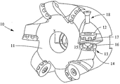
工具ホルダーの一つの実施形態は、図1に示されているように、スローアウェイチップのためのスライス工具10であっても良い。図1における工具ホルダーの実施形態は、6個の丸い形状のスローアウェイチップ12を受け入れるための6個のポケットを含んでいる。丸い形状の切削用チップ12は、ポケット13内に固定することができる。工具ホルダーのこの実施形態のポケット13は、底面14と側壁15とを含んでいる。回転防止ストッパ16が側壁15から突出している。回転防止ストッパ16は、スローアウェイチップ12内の凹部17内に少なくとも部分的に延びていて、切削用チップがねじ18によって工具ホルダー10に固定された後に切削用チップ12の回転を阻止する。
One embodiment of the tool holder may be a slicing
工具本体12は、機械、機械構成部品、構造的形状、工具、装置及びその他の物品において使用される金属、合金、樹脂又はセラミックのような適切な工業材料によって作ることができる。これらの材料の硬度、強度、機械加工性、寸法的安定性、非燃焼性及び腐食、酸、溶剤及び熱に対する耐性は、このような適当な工業材料の特性を特徴付けることができる。このような適当な工業材料のリストの一つの例としては、限定的ではないが、ア
ルミニューム、ベリリウム、黄銅、青銅、鋳鉄、銅、鉛、マグネシウム、鋼、タンタル、亜鉛、ジルコニウム及びその他の種々の商標登録された或いは商標登録されていない合金、ガラス及び磁器のようなセラミック並びにABS樹脂、アセタール樹脂、アクリル樹脂、フルオロカーボンポリマー、ナイロン、フェノールホルムアルデヒド樹脂、ポリブチレンテレフタレート、ポリカーボネート、ポリエチレン、ポリフェニレンオキサイド、ポリプロピレン、ポリスチレン、ポリビニルクロライド、強化プラスチック(FRP)及びフェノールホルムアルデヒドのような樹脂がある。
The
本発明の工具ホルダーは、少なくとも1つのポケットを含んでいる。工具ホルダー内のポケットは、切削用チップを受け入れる設計とされている。図1に示されているようなある種の実施形態においては、ポケット13は、底面14及び側壁15を有している。底面14は、工具ホルダー内にある間、切削用チップを支持する。側壁15もまた、切削用チップと係合して、フライス又はその他の加工作業中にチップを更に支持することができる。
The tool holder of the present invention includes at least one pocket. The pockets in the tool holder are designed to accept cutting tips. In certain embodiments, such as that shown in FIG. 1, the
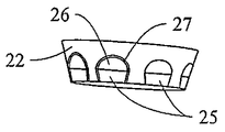
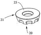
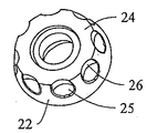
工具ホルダーの実施形態は回転防止ストッパを更に含んでいる。回転防止ストッパは、工具ホルダーのポケット内でのチップの回転を阻止する。少なくとも1つの凹部を含んでいる切削用チップは、回転防止ストッパが切削用チップの凹部内に延びている状態でポケット内に固定される。図2の2A,2B及び2Cに示されている丸い形状のチップ20は、切り刃21、側壁22、頂部切り屑破壊構造23、底面24及びチップの側壁22の周囲の多数の凹面25を含んでいる。チップの凹面26の端縁27は、滑らかに融和して丸みを形成していても良い。典型的には、丸い形状のチップが配置され、次いで、フライスホルダー上に形成されたポケット内に締結される(図1)。回転防止ストッパは、工具ホルダー内のチップ用ポケットのうちの少なくとも1つに対応している。従って、回転防止ストッパは、チップ用ポケット内に又はチップ自体上に組み入れても良い。回転防止段部に対応する凹部が、チップの他方及びチップ用ポケット内に組み入れられている。
The embodiment of the tool holder further includes an anti-rotation stopper. The anti-rotation stopper prevents the tip from rotating in the pocket of the tool holder. The cutting tip including at least one recess is fixed in the pocket with the anti-rotation stopper extending into the recess of the cutting tip. The round-shaped
「実質的に平ら」という用語は、面が平らすなわち平坦であることを示している。回転防止段部の面は、これらの面が先端の回転防止段部及び凹部又は局部化された部分の係合を接触状態に維持するような方法で製造される場合に、実質的に平らであると考えられるべきである。 The term “substantially flat” indicates that the surface is flat or flat. The surfaces of the anti-rotation steps are substantially flat when they are manufactured in such a way that the engagement of the anti-rotation steps at the tip and the recesses or localized parts is maintained in contact. Should be considered.
本発明の工具ホルダーは、凹部に対して相補的な形状の回転防止ストッパを必要としない。この非相補的な要件は、ポケット及びチップがより容易に製造され且つ相補的である工具ホルダー及びチップよりも正確に固定されるのを可能にする。本発明において提供されるポケット内の回転防止ストッパは、最近の米国特許第6,238,133号におけるような従来技術の斜めに配向された三次元面の代わりに少なくとも2つの実質的に平らな面を有している。従って、これは、軸線方向による方法よりもむしろタンジェンシャルな方法を使用するポケットの製造を可能にする。タンジェンシャル方法は、最近の米国特許第6,238,133号に記載されているようなポケットを形成する方法における場合のようにポケットの軸線(一般的な)方向ではなくポケットの底面に対して接線方向にポケットに近づくことによって切削工具のポケットを形成することを含む。 The tool holder of the present invention does not require an anti-rotation stopper having a shape complementary to the recess. This non-complementary requirement allows pockets and tips to be more easily manufactured and fixed more accurately than tool holders and tips that are complementary. The anti-rotation stopper in the pocket provided in the present invention replaces the prior art diagonally oriented three-dimensional surface as in recent US Pat. No. 6,238,133 with at least two substantially flat surfaces. Has a surface. This therefore enables the manufacture of pockets using a tangential method rather than an axial method. The tangential method is not relative to the pocket axis (general) direction but to the bottom of the pocket as in the method of forming a pocket as described in recent US Pat. No. 6,238,133. Forming the pocket of the cutting tool by approaching the pocket tangentially.
図3に示されたもう一つ別の実施形態においては、工具ホルダーは、ポケットの下方壁32及び上方壁33を含んでいる側壁31を有しているポケット33と、2つの実質的に平らな面35、中央の実質的に平らな面36及び底面37を含んでいる回転防止ストッパ34とを有している。任意的な上方壁33は、湾曲しているか又は角度が付けられているか又は湾曲及び角度の両方の組み合わせによって作っても良い。2つの実質的に平らな面35及び中央の実質的に平らな面36は、この実施形態においては、非傾斜二次元幾何学的構造の形態として記載することができるポケット33の底面37に直角である。更に、
各ポケット33内の実質的に平らな3つの面を結合する唯一の一体化された回転防止ストッパが存在するけれども、最大の位置決め精度及び簡素化された製造過程の両方が達成されても良い。
In another embodiment shown in FIG. 3, the tool holder includes a
Although there is a single integrated anti-rotation stop that joins the three substantially flat surfaces within each
ポケット33の底面37は切削作業中にチップを支持するけれども、図2の2A乃至2Cに示された切削用チップ20の凹部の凹んだ面26又は端縁27は、チップ20の回転を防止するために回転防止ストッパ34の端縁のどちらかと接触している。
Although the
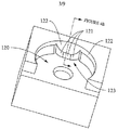
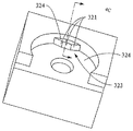
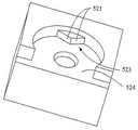
回転防止ストッパは、図1乃至3に示された形状に限られる必要はない(図4A,4B,4C,4D,4E,4F,4G及び4Hを参照)。回転防止ストッパは、少なくとも2つの平らな面を含んでおり且つ平らであっても良いし又は平らでなくても良い付加的な面を含んでいても良い。図4A及び4Bに示された実施形態は、回転防止ストッパ123を含んでおり且つ3つの平らな面121と4つの湾曲した面122を含んでいる面取り部とを有している。図4A及び4Bの実施形態における3つの平らな面は、底面124に実質的に直角である。この実施形態における湾曲した面である面取り部122は円形の断面を有している。図2Bに示された面取り部122は、標準的なボールエンドミルによって回転防止ストッパの頂部をフライス加工することによって成形することができる(図6の6B参照)。この面取り部は、工具ホルダー内に固定されたときに、ポケットの少なくとも一部分がチップを支持するのを可能にする如何なる形状であっても良い。例えば、図4の4Cに示されている簡単な直線状の面取り部を使用しても良い。図4Dに示された回転防止ストッパ323は、面321が底面324に実質的に直角である頂部端縁の面取り部の無い4つの実質的に平らな面321及び324を有している。図4の4E及び4Fの工具ホルダーの実施形態は、回転防止ストッパ23上の底面424及び524に実質的に直角であるちょうど2つの平らな面421及び521を含んでいる回転防止ストッパ423及び523を有している。面取り部422は、図4の4Eの実施形態に含まれている。
The anti-rotation stopper need not be limited to the shape shown in FIGS. 1 to 3 (see FIGS. 4A, 4B, 4C, 4D, 4E, 4F, 4G and 4H). The anti-rotation stopper includes at least two flat surfaces and may include additional surfaces that may or may not be flat. The embodiment shown in FIGS. 4A and 4B includes an
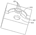
図4の4Gの工具ホルダーの実施形態は、底面624に実質的に直角である4つの平らな面621を有している回転防止ストッパ623を含んでいる。一方、図4の4H内の工具ホルダーの実施形態は、底面724に直角である2つの平らな面を有している回転防止ストッパ723と、同じく底面724に直角である湾曲した面725とを含んでいる。工具ホルダーのこれらの実施形態は、回転防止ストッパを含んでいる種々の工具ホルダーの単なる例であり且つここに示された実施形態の各々の特徴又は本明細書から当業者によって引き出すことができるその他の特徴を組み合わせても良い本発明の実施形態を限定することは意味していない。
The 4G tool holder embodiment of FIG. 4 includes an
本発明の実施形態は、工具ホルダー内に丸い形状のチップを正確に且つ確実に位置決めすることを可能にする。正確に且つ確実に位置決めされたチップは、チップの寿命の性能及び統一性を改良することができる。本発明の工具ホルダーは、如何なる数の切削用チップと共に使用しても良い。回転防止ストッパと係合する切削用チップ内の凹部の形状は、回転防止ストッパの形状に適合する必要はない。実際には、如何なる形状の多数の凹んだ面を含んでいる切削用チップを使用しても良い。丸い形状のチップの側壁の近くに簡単な形状の幾何学的構造を工具ホルダーと共に使用しても良い。 Embodiments of the present invention allow a round shaped tip to be accurately and reliably positioned within a tool holder. A chip that is accurately and reliably positioned can improve chip life performance and uniformity. The tool holder of the present invention may be used with any number of cutting tips. The shape of the recess in the cutting tip that engages with the anti-rotation stopper need not match the shape of the anti-rotation stopper. In practice, a cutting tip including a number of recessed surfaces of any shape may be used. A simple shaped geometry may be used with the tool holder near the side wall of the round shaped tip.
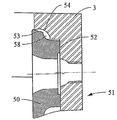
このチップは、少なくとも3つの位置主として2つの位置でポケットと接触する。一つの例として、チップ50は図5に示されたポケット51内に着座せしめられても良い。チップ50の底部は、ポケット51の底面52と接触している。更に、チップ50の側壁53の上方部分は、典型的には丸い形状のチップのための接触位置であるポケット51の上方部分に設けられた標準的な(加工において標準的なテーパーがつけられたボールミルによって形成されたような)角度が付けられた面取り部54又は(加工において標準的なボールミルによって形成された)湾曲した面取り部54と接触する。更に、図5の工具ホル
ダーの実施形態においては、チップ50と、チップの凹んだ面58と図3に示されたポケットの端縁38のいずれかとの間のポケット51との間に接触が存在する。端縁38の凹状輪郭における接触を有する利点は、加工作業中に、この形状の接触が、チップと工具ホルダーとの間のより大きな安定性及びより少ない摺動傾向を提供する点である。上記の接触の結合された効果は、ポケット内でのチップの回転を防止するために効率が良く且つ安定した機構を提供する。端縁38は、端縁の面取り部又は丸味を含むために尖ったコーナーから変形させても良い。
The tip contacts the pocket in at least three locations, primarily two. As an example, the
本発明の工具ホルダーの実施形態は、チップのより正確な着座を可能にする。チップの凹んだ面は、回転防止ストッパの端縁の凹状の輪郭においてポケットと接触して、安定した接触を提供する。一つの実施形態においては、回転防止ストッパの頂部の端縁は、ポケットの壁の上方部分を加工する際における、少なくとも2つの実質的に平らな面と標準的なボールミルによって形成された球との間の交差の結果である。 The tool holder embodiment of the present invention allows for more accurate seating of the chip. The concave surface of the tip contacts the pocket at the concave contour of the edge of the anti-rotation stopper to provide stable contact. In one embodiment, the top edge of the anti-rotation stopper is formed by at least two substantially flat surfaces and a sphere formed by a standard ball mill when machining the upper portion of the pocket wall. The result of the intersection between.
工具ホルダーの実施形態は重要な利点を提供する。すなわち、本発明においては、チップ受け入れポケット内の回転防止面は、米国特許第6,238,133号におけるように斜めの三次元幾何学的構造の形態の凹面ではなく、斜めではない二次元の幾何学的構造の形態の少なくとも2つの実質的に平らな面によって構成されている。 The embodiment of the tool holder offers important advantages. That is, in the present invention, the anti-rotation surface in the chip receiving pocket is not a concave surface in the form of an oblique three-dimensional geometric structure as in US Pat. It is constituted by at least two substantially flat surfaces in the form of a geometric structure.
更に、本発明においては、米国特許第6,238,133号における相補的な形状の幾何学的構造ではなくチップの幾何学的構造とポケットとの間の相補的な関係が存在する必要はない。 Further, in the present invention, there is no need for a complementary relationship between the tip geometry and the pockets, rather than the complementary geometry in US Pat. No. 6,238,133. .
規則的な丸い形状のチップは、ポケットの壁の上方部分で接触するかも知れない。回転防止機構を備えた丸い形状のチップのために、少なくとも1つの付加的な接触を有する必要がある。本発明の工具ホルダーの実施形態においては、チップは、米国特許第6,238,133号に記載されているポケットと工具チップとの直線状の接触ではなく、ある点におけるポケットの壁の下方部分と接触する。従って、本発明の工具ホルダーは、工具ホルダー内の製造過程の性能及び着座の統一性を改良するより安定した接触を提供する。ある種の実施形態においては、上記した点接触は、前記2つの実質的に平らな面の頂部に形成された端縁によって生じる。 Regular round shaped tips may touch the upper part of the pocket wall. For round shaped tips with anti-rotation mechanisms, it is necessary to have at least one additional contact. In an embodiment of the tool holder of the present invention, the tip is not the linear contact between the pocket and the tool tip as described in US Pat. No. 6,238,133, but at a lower portion of the pocket wall at some point. Contact with. Thus, the tool holder of the present invention provides a more stable contact that improves manufacturing process performance and seating uniformity within the tool holder. In certain embodiments, the point contact described above is caused by an edge formed at the top of the two substantially flat surfaces.
実質的に平らな幾何学的構造により、本発明は、軸線方向方法すなわち一般的な方法ではなくタンジェンシャルな方法を使用するポケットの製造を可能にする。タンジェンシャル方法においては、切削工具は、米国特許第6,238,133号におけるようなポケットの底面に対して接線方向又は平行な方向でポケットに接近する。従って、本発明における設計は、製造の容易性のためのより多くの任意の選択肢を提供する。 With a substantially flat geometric structure, the present invention allows the manufacture of pockets using an axial method, ie a tangential method rather than a general method. In the tangential method, the cutting tool approaches the pocket in a tangential or parallel direction to the bottom surface of the pocket as in US Pat. No. 6,238,133. Thus, the design in the present invention offers more optional options for ease of manufacture.
一般的な方法すなわち軸線方向の方法はフライス切削工具内にポケットを製造するために典型的に使用されることは良く知られている。ポケットを製造するために使用される工具は、ポケットの軸線に平行な方向で接近し且つポケットを加工し、従って、切削工具のための逃げ空間がポケットの軸線に沿って提供されなければならない。この意味で、ポケットを製造するための軸線方法は、フライスのために利用できる直径当たりのポケットの数又は歯の数を制限する。 It is well known that general or axial methods are typically used to produce pockets in milling tools. The tool used to manufacture the pocket must approach and machine the pocket in a direction parallel to the pocket axis, and therefore a clearance space for the cutting tool must be provided along the pocket axis. In this sense, the axial method for manufacturing the pockets limits the number of pockets or teeth per diameter available for milling.
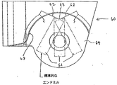
ポケットを製造するためのタンジェンシャル方法はより自由度があり、一つの実施形態が図6の図6A及び6Bに示されている。図6の6Aに示されているように、標準的な90°エンドミル61は、ポケットの底面に平行な方向で、又は言い換えれば、ポケットの底面64に対する接線方向からポケットに接近しても良い。図6の6A及び6Bに示されている実施形態においては、90°エンドミルは、粗い切削のためにポケットの側壁69
を加工するポケット60を最初に開き、これと同時に、2つの実質的に平らな面62を加工し且つ任意的に第3の実質的に平らな面63を加工する。図6の6Bに示されているように、標準的なボールミル65は、3つの実質的に平らな面62及び63との交差位置に凹状の輪郭と端縁67とを自然に形成するポケットの側壁69の上方部分を同じく接線方向に加工することができる。
The tangential method for manufacturing the pocket is more flexible and one embodiment is shown in FIGS. 6A and 6B of FIG. As shown in FIG. 6A, a standard 90 °
The
このタンジェンシャルな製造方法は、軸線方向の製造方法よりもカッター本体内の直径毎により多くのポケット又は切削歯が形成されるのを可能にする。
付加的なポケットを備えた工具ホルダーを製造する能力を有することには幾つかの利点がある。例えば、切削用チップの寿命は、材料の切除速度を維持し又は改良しつつ、加工中の送り速度を遅くすることによって改良することができる。歯間の距離がより短いフライスもまた、各歯に分配される応力を減らすことによってカッター本体の寿命を改良することができる。より多くの歯はまた、インコネル、チタン等の幾つかの加工が困難な材料の加工において利点を有するであろう。
This tangential manufacturing method allows more pockets or cutting teeth to be formed for each diameter in the cutter body than an axial manufacturing method.
Having the ability to manufacture a tool holder with additional pockets has several advantages. For example, the life of a cutting tip can be improved by slowing the feed rate during processing while maintaining or improving the material cutting speed. Millers with shorter distances between teeth can also improve the life of the cutter body by reducing the stress distributed to each tooth. More teeth will also have advantages in processing some difficult to process materials such as Inconel, Titanium.
例えば、本発明の実施形態におけるタングステンを基礎とする超硬合金又はサーメットとすることができるチップの凹んだ面は、底面に対して殆ど直角であるか又は好ましくは底面に対して直角から1乃至2度のように若干外れており、次いで、部分的な湾曲した半径によって形成されている複雑な幾何学的構造ではなく簡単な球状面へと滑らかに延びている簡単な幾何学的構造を有しても良く且つ従来技術におけるように中心部分にテーパー(約15°)が付けられた湾曲したストッパ面ばかりでなくチップ外周近くに連続する正弦曲線を含んでいる。 For example, the recessed surface of the chip, which can be a tungsten-based cemented carbide or cermet in embodiments of the present invention, is almost perpendicular to the bottom surface, or preferably 1 to 1 from a right angle to the bottom surface. It has a simple geometric structure that is slightly off, such as 2 degrees, and then smoothly extends to a simple spherical surface rather than a complex geometric structure formed by a partially curved radius. As well as in the prior art, it includes not only a curved stopper surface with a taper (about 15 °) in the central portion but also a continuous sinusoid near the tip periphery.
以上、本発明の工具ホルダーの実施形態を説明したけれども、当業者には種々の変形、変更及び付加が明らかとなるかも知れない。例えば、回転防止ストッパを丸いチップと組み合わせた工具ホルダーに対する使用に関して説明したけれども、その他の湾曲した切削端縁又は真っ直ぐな切削端縁を備えた実施形態に組み入れても良い。更に、ここに説明した実施形態は回転防止ストッパに対して構成され、より多数の回転防止ストッパを、2つの平らな面を含んでいる少なくとも1つの回転防止ストッパを含んでいる工具ホルダー内に組み入れても良い。 Although the embodiment of the tool holder of the present invention has been described above, various modifications, changes and additions may become apparent to those skilled in the art. For example, although the anti-rotation stopper has been described for use with a tool holder in combination with a round tip, it may be incorporated into embodiments with other curved or straight cutting edges. Further, the embodiments described herein are configured for anti-rotation stoppers, and a greater number of anti-rotation stoppers are incorporated into a tool holder that includes at least one anti-rotation stopper that includes two flat surfaces. May be.
工具ホルダーの実施形態は、丸い形状のチップを正確に且つ確実に位置決めするために使用して切削作業内のチップの寿命の性能及び統一性を改良しても良い。工具ホルダーの実施形態は、ホルダー上のポケットの幾何学的構造によって製造がより容易であり且つ特別な工具ホルダー上により多数のポケット又は歯が形成されるのを可能にして工具の潜在的な用途を広げることができる。 Tool holder embodiments may be used to accurately and reliably position round shaped tips to improve tip performance and uniformity within the cutting operation. Tool holder embodiments are easier to manufacture due to the geometric structure of the pockets on the holder and allow a larger number of pockets or teeth to be formed on a special tool holder, potentially using the tool Can be spread.
Claims (54)
チップ用ポケットを備えた工具ホルダーであって、前記チップ用ポケットが側壁を備えており、単一の回転防止ストッパが前記側壁から突出しており、該単一の回転防止ストッパが2つの面を備えている、前記工具ホルダーと、
前記チップ用ポケット内に設けられた切削用チップであって、丸い形状を有しており、連続している切り刃と凹部とを備えている、前記切削用チップと、を備えており、
前記単一の回転防止ストッパの前記2つの面が少なくとも部分的に前記凹部内へと延びており、前記単一の回転防止ストッパは、前記2つの面の一方又は他方と前記凹部との間の点接触によって、前記チップ用インサート内の切削用チップのいずれの方向の回転をも阻止するようになされている、ことを特徴とする切削工具。 A cutting tool,
A tool holder having a tip pocket, wherein the tip pocket has a side wall, a single anti-rotation stopper projects from the side wall, and the single anti-rotation stopper has two surfaces. The tool holder;
A cutting tip provided in the tip pocket, having a round shape, comprising a continuous cutting blade and a recess, and the cutting tip,
The two surfaces of the single anti-rotation stopper extend at least partially into the recess, and the single anti-rotation stopper is between one or the other of the two surfaces and the recess. A cutting tool characterized in that, by point contact, rotation in any direction of the cutting tip in the insert for tip is prevented.
チップ用ポケットを備えた工具ホルダーであって、該チップ用ポケットは底面と側壁と単一の回転防止ストッパとを備えており、該単一の回転防止ストッパは2つの面を備えており、該2つの面は前記側壁から突出しており且つ前記底面と交差している、前記工具ホルダーと、
前記チップ用ポケット内に設けられた切削用チップであって、丸い形状を有しており且つ連続している切り刃と凹部とを備えている、前記切削用チップと、を備えており、
前記チップ用ポケットの前記単一の回転防止ストッパの前記2つの面の各々が、少なくとも部分的に前記凹部内へと延びており、
前記チップ用ポケット内での前記切削用チップの第一の方向の回転が、前記単一の回転防止ストッパの前記2つの面のうちの一方と前記凹部との点接触によって阻止され、
前記チップ用ポケット内での前記切削用チップの第二の方向の回転が、前記単一の回転防止ストッパの前記2つの面のうちの他方と前記凹部との点接触によって阻止されるようになされている、ことを特徴とする切削工具。 A cutting tool,
A tool holder having a tip pocket, the tip pocket having a bottom surface, a side wall, and a single anti-rotation stopper, the single anti-rotation stopper having two surfaces, Two tool surfaces projecting from the side wall and intersecting the bottom surface;
A cutting tip provided in the tip pocket, the cutting tip having a round shape and having a continuous cutting blade and a recess, and
Each of the two surfaces of the single anti-rotation stopper of the chip pocket extends at least partially into the recess;
Rotation of the cutting tip in the first direction within the tip pocket is prevented by point contact between one of the two surfaces of the single anti-rotation stopper and the recess;
Rotation of the cutting tip in the second direction within the tip pocket is prevented by point contact between the other of the two surfaces of the single anti-rotation stopper and the recess. A cutting tool characterized by that.
チップ用ポケットを備えた工具ホルダーであって、該チップ用ポケットは側壁と単一の回転防止ストッパとを備えており、該回転防止ストッパは前記側壁から突出しており且つ2つの面を備えている、前記工具ホルダーと、
前記チップ用ポケット内に設けられた切削用チップであって、丸い形状を有しており且つ連続している切り刃と凹部とを備えている、前記切削用チップと、を備えており、
前記単一の回転防止ストッパの前記2つの面の各々が少なくとも部分的に前記凹部内へと延びており、前記単一の回転防止ストッパは、前記チップ用ポケット内での前記切削用チップの両方向の回転を、前記2つの面の一方又は他方の特定の領域と前記凹部との接触によって阻止するようになされている、ことを特徴とする切削工具。 A cutting tool,
A tool holder with a tip pocket, the tip pocket having a side wall and a single anti-rotation stopper, the anti-rotation stopper protruding from the side wall and having two faces The tool holder;
A cutting tip provided in the tip pocket, the cutting tip having a round shape and having a continuous cutting blade and a recess, and
Each of the two surfaces of the single anti-rotation stopper extends at least partially into the recess, and the single anti-rotation stopper is in both directions of the cutting tip within the tip pocket. The cutting tool is characterized in that the rotation is prevented by contact between a specific region of one or the other of the two surfaces and the concave portion.
する請求項36に記載の切削工具。 37. A cutting tool according to claim 36, wherein each of the three surfaces of the tip pocket is a substantially flat surface.
チップ用ポケットを備えた工具ホルダーであって、該チップ用ポケットは底面と側壁と単一の回転防止ストッパとを備えており、該単一の回転防止ストッパが2つの面を備えており、該2つの面は前記側壁から突出しており且つ前記底面と交差している、前記工具ホルダーと、
前記チップ用ポケット内に設けられた切削用チップであって、丸い形状を有しており且つ連続している切り刃と凹部とを備えている、前記切削用チップと、を備えており、
前記チップ用ポケットの前記単一の回転防止ストッパの前記2つの面の各々が少なくとも部分的に前記凹部内へと延びており、
前記チップ用ポケット内での前記切削用チップの第一の方向の回転が、前記単一の回転防止ストッパの前記2つの面のうちの一方の特定の領域と前記凹部との接触によって阻止され、
前記チップ用ポケット内での前記切削用チップの第二の方向の回転が、前記単一の回転防止ストッパの前記2つの面のうちの他方の特定の領域と前記凹部との接触によって阻止されるようになされている、ことを特徴とする切削工具。 A cutting tool,
A tool holder having a chip pocket, the chip pocket having a bottom surface, a side wall, and a single anti-rotation stopper, the single anti-rotation stopper having two surfaces, Two tool surfaces projecting from the side wall and intersecting the bottom surface;
A cutting tip provided in the tip pocket, the cutting tip having a round shape and having a continuous cutting blade and a recess, and
Each of the two surfaces of the single anti-rotation stopper of the chip pocket extends at least partially into the recess;
Rotation of the cutting tip in the first direction within the tip pocket is prevented by contact of one particular area of the two surfaces of the single anti-rotation stopper with the recess.
Rotation of the cutting tip in the second direction in the tip pocket is prevented by contact of the other specific area of the two surfaces of the single anti-rotation stopper with the recess. The cutting tool characterized by being made.
Applications Claiming Priority (2)
| Application Number | Priority Date | Filing Date | Title |
|---|---|---|---|
| US10/414,358 | 2003-04-15 | ||
| US10/414,358 US7722297B2 (en) | 2003-04-15 | 2003-04-15 | Antirotation tool holder and cutting insert |
Related Parent Applications (1)
| Application Number | Title | Priority Date | Filing Date |
|---|---|---|---|
| JP2011123886A Division JP5346061B2 (en) | 2003-04-15 | 2011-06-02 | Anti-rotation tool holder and cutting tip tool |
Publications (2)
| Publication Number | Publication Date |
|---|---|
| JP2012131027A true JP2012131027A (en) | 2012-07-12 |
| JP5518913B2 JP5518913B2 (en) | 2014-06-11 |
Family
ID=33309493
Family Applications (3)
| Application Number | Title | Priority Date | Filing Date |
|---|---|---|---|
| JP2006509006A Expired - Fee Related JP4908201B2 (en) | 2003-04-15 | 2004-03-02 | Anti-rotation tool holder and cutting tip tool |
| JP2011123886A Expired - Fee Related JP5346061B2 (en) | 2003-04-15 | 2011-06-02 | Anti-rotation tool holder and cutting tip tool |
| JP2012021971A Expired - Fee Related JP5518913B2 (en) | 2003-04-15 | 2012-02-03 | Anti-rotation tool holder and cutting tip tool |
Family Applications Before (2)
| Application Number | Title | Priority Date | Filing Date |
|---|---|---|---|
| JP2006509006A Expired - Fee Related JP4908201B2 (en) | 2003-04-15 | 2004-03-02 | Anti-rotation tool holder and cutting tip tool |
| JP2011123886A Expired - Fee Related JP5346061B2 (en) | 2003-04-15 | 2011-06-02 | Anti-rotation tool holder and cutting tip tool |
Country Status (11)
| Country | Link |
|---|---|
| US (4) | US7722297B2 (en) |
| EP (2) | EP2364804A1 (en) |
| JP (3) | JP4908201B2 (en) |
| KR (1) | KR101203783B1 (en) |
| CN (1) | CN100479959C (en) |
| CA (1) | CA2520134C (en) |
| MX (1) | MXPA05010910A (en) |
| NO (2) | NO20055262L (en) |
| RU (1) | RU2338630C2 (en) |
| TW (1) | TWI320730B (en) |
| WO (1) | WO2004094092A1 (en) |
Cited By (2)
| Publication number | Priority date | Publication date | Assignee | Title |
|---|---|---|---|---|
| JP2013075337A (en) * | 2011-09-30 | 2013-04-25 | Hitachi Tool Engineering Ltd | Cutting edge exchange type cutting tool |
| JP2020504025A (en) * | 2017-01-18 | 2020-02-06 | サンドビック インテレクチュアル プロパティー アクティエボラーグ | Indexable cutting inserts for milling tools |
Families Citing this family (65)
| Publication number | Priority date | Publication date | Assignee | Title |
|---|---|---|---|---|
| US7722297B2 (en) * | 2003-04-15 | 2010-05-25 | Tdy Industries, Inc. | Antirotation tool holder and cutting insert |
| US7220083B2 (en) | 2003-10-15 | 2007-05-22 | Tdy Industries, Inc. | Cutting insert for high feed face milling |
| JP4857958B2 (en) * | 2006-01-11 | 2012-01-18 | 三菱マテリアル株式会社 | Round piece insert removable cutting tool and round piece insert |
| DE102006035182A1 (en) * | 2006-07-29 | 2008-01-31 | Hartmetall-Werkzeugfabrik Paul Horn Gmbh | Tool system, has cutting blade protruding over holder, where holder is provided with supporting part protruding towards projection of cutting blade and forming supporting surface for partial attachment of cutting tool |
| US7905687B2 (en) * | 2007-01-16 | 2011-03-15 | Tdy Industries, Inc. | Cutting insert, tool holder, and related method |
| US20080228313A1 (en) * | 2007-03-05 | 2008-09-18 | Mori Seiki Usa, Inc. | Device and Method for Turning In Virtual Planes |
| US7905689B2 (en) | 2008-05-07 | 2011-03-15 | Tdy Industries, Inc. | Cutting tool system, cutting insert, and tool holder |
| DE102008037915B3 (en) | 2008-08-14 | 2009-08-13 | Kennametal Inc. | Indexable insert |
| DE202008018646U1 (en) * | 2008-08-31 | 2017-03-24 | Iscar Ltd. | cutting insert |
| US7976250B2 (en) * | 2009-02-12 | 2011-07-12 | Tdy Industries, Inc. | Double-sided cutting inserts for high feed milling |
| US8491234B2 (en) * | 2009-02-12 | 2013-07-23 | TDY Industries, LLC | Double-sided cutting inserts for high feed milling |
| JP5110400B2 (en) * | 2009-03-24 | 2012-12-26 | 日立ツール株式会社 | Replaceable cutting tool |
| US9586264B2 (en) | 2009-04-28 | 2017-03-07 | Kennametal Inc. | Double-sided cutting insert for drilling tool |
| SE534506C2 (en) * | 2009-04-30 | 2011-09-13 | Seco Tools Ab | Cutting tool and a cutting holder for a cutting tool |
| KR101103216B1 (en) * | 2009-05-19 | 2012-01-05 | 대구텍 유한회사 | Double-sided cutting insert with circular shape and cutting tool using the same |
| US8573903B2 (en) * | 2009-11-03 | 2013-11-05 | Kennametal Inc. | Round cutting insert with anti-rotation feature |
| US8807884B2 (en) | 2009-12-18 | 2014-08-19 | Kennametal Inc. | Tool holder for multiple differently-shaped cutting inserts |
| CN102189391A (en) * | 2010-03-10 | 2011-09-21 | 新武企业有限公司 | Axial machining method |
| SE534832C2 (en) * | 2010-05-10 | 2012-01-17 | Sandvik Intellectual Property | Indexable cutter for milling tools |
| IL206272A (en) * | 2010-06-07 | 2014-08-31 | Iscar Ltd | Cutting insert and milling tool |
| USD635164S1 (en) | 2010-06-09 | 2011-03-29 | Kennametal Inc. | Cutting insert |
| US8459904B2 (en) * | 2010-06-23 | 2013-06-11 | Kennametal Inc. | Cutting insert and holder for rotating applications |
| EP2455172B1 (en) * | 2010-11-19 | 2013-01-16 | SECO TOOLS AB (publ) | Cutting insert with evolutive wedge or clearance angle and toolholder using such a cutting insert |
| SE535441C2 (en) * | 2010-12-28 | 2012-08-07 | Sandvik Intellectual Property | Clearing tools and head and cutters for this |
| AT12527U1 (en) * | 2011-02-24 | 2012-07-15 | Ceratizit Austria Gmbh | CUTTING INSERT FOR DISCONTINUING MACHINING |
| USD658218S1 (en) | 2011-03-28 | 2012-04-24 | Kennametal Inc. | Round cutting insert with reverse anti-rotation feature |
| US8657539B2 (en) * | 2011-03-28 | 2014-02-25 | Kennametal Inc. | Round cutting insert with reverse anti-rotation feature |
| US9379571B2 (en) | 2011-07-11 | 2016-06-28 | Delphi Technologies, Inc. | Electrical charging system having energy coupling arrangement for wireless energy transmission therebetween |
| USD673194S1 (en) * | 2011-07-11 | 2012-12-25 | Kennametal Inc. | Cutting insert |
| RU2570682C1 (en) * | 2011-10-07 | 2015-12-10 | Тунгалой Корпорейшн | Cutting tool with changeable cutting edge |
| US8882402B2 (en) | 2011-11-22 | 2014-11-11 | Kennametal Inc. | Anti-rotation mounting mechanism for a round insert |
| US8708613B2 (en) * | 2012-04-10 | 2014-04-29 | Iscar, Ltd. | Left-handed and right-handed cutting tool |
| US8858130B2 (en) | 2012-04-24 | 2014-10-14 | Kennametal Inc. | Indexable circular cutting insert |
| USD709110S1 (en) | 2012-04-24 | 2014-07-15 | Kennametal Inc. | Cutting insert |
| EP2664399B1 (en) * | 2012-05-15 | 2017-01-04 | VARGUS Ltd. | Cutting tool |
| JP5853297B2 (en) * | 2012-07-24 | 2016-02-09 | 住友電工ハードメタル株式会社 | Replaceable cutting tool |
| USD708237S1 (en) * | 2012-09-10 | 2014-07-01 | Sumitomo Electric Hardmetal Corp. | Cutting insert |
| US9011049B2 (en) | 2012-09-25 | 2015-04-21 | Kennametal Inc. | Double-sided cutting inserts with anti-rotation features |
| US9283626B2 (en) | 2012-09-25 | 2016-03-15 | Kennametal Inc. | Double-sided cutting inserts with anti-rotation features |
| US9649700B2 (en) | 2013-03-18 | 2017-05-16 | Kennametal Inc. | Method for manufacturing an insert-receiving pocket wall with a compound radius |
| USD762739S1 (en) * | 2013-08-15 | 2016-08-02 | Magna-Sonic Stress Testers, Inc. | Pipe end refacing tool |
| JP6253093B2 (en) * | 2014-01-24 | 2017-12-27 | 住友電工ハードメタル株式会社 | Cutting insert and cutting edge exchangeable cutting tool |
| JP6330913B2 (en) * | 2015-03-05 | 2018-05-30 | 株式会社タンガロイ | Cutting insert and cutting edge exchangeable rotary cutting tool |
| EP3299102B1 (en) * | 2015-05-19 | 2024-09-18 | Tungaloy Corporation | Tool body in combination with a first cutting insert and a second cutting insert |
| WO2016203843A1 (en) * | 2015-06-19 | 2016-12-22 | 株式会社タンガロイ | Tool body and cutting tool |
| US10246999B2 (en) | 2016-03-23 | 2019-04-02 | Caterpillar Paving Products Inc. | Locking system to prevent rotation of toolholder |
| RU2626481C1 (en) * | 2016-04-19 | 2017-07-28 | Федеральное государственное бюджетное образовательное учреждение высшего профессионального образования "Национальный минерально-сырьевой университет "Горный" | Method of wear-resistant indexable pick manufacture |
| US9845861B1 (en) * | 2016-05-26 | 2017-12-19 | GM Global Technology Operations LLC | Rotatable assembly including a coupling interface |
| JP6842940B2 (en) * | 2017-02-08 | 2021-03-17 | ダイジ▲ェ▼ット工業株式会社 | Rotating cutting tool with replaceable cutting edge |
| US10646927B2 (en) * | 2018-02-19 | 2020-05-12 | Iscar, Ltd. | Round double-sided cutting insert having a peripheral surface provided with protruding indexing latches, insert holder therefor and cutting tool |
| EP3643439B1 (en) * | 2018-10-26 | 2022-07-13 | Seco Tools Ab | A cutting tool |
| CN109822141A (en) * | 2019-03-26 | 2019-05-31 | 哈尔滨汽轮机厂有限责任公司 | Finishing and roughing inserts for machining superalloy blades of steam turbines |
| US11612943B2 (en) * | 2019-08-01 | 2023-03-28 | Iscar, Ltd. | Insert adaptor and turning tool comprising same |
| KR102253026B1 (en) * | 2019-10-28 | 2021-05-17 | 한국야금 주식회사 | Cutting insert and Tool mounted withthere |
| US11534842B2 (en) | 2019-11-02 | 2022-12-27 | Kennametal Inc. | Cutting insert and cutting system comprising cutting insert |
| USD1040196S1 (en) * | 2020-12-18 | 2024-08-27 | Sumitomo Electric Hardmetal Corp. | Cutting tool |
| JP7012948B1 (en) | 2021-03-10 | 2022-01-31 | 株式会社タンガロイ | Tool body of replaceable cutting tool |
| US11806796B2 (en) | 2021-03-15 | 2023-11-07 | Kennametal Inc. | Cutting insert and cutting tool comprising cutting insert |
| US11786982B2 (en) | 2021-04-26 | 2023-10-17 | Kennametal Inc. | Cutting tool comprising toolholder and round cutting insert and method for repositioning the round cutting insert in a pocket of the toolholder |
| US12544841B2 (en) | 2021-04-26 | 2026-02-10 | Kennametal Inc. | Cutting tool comprising toolholder and round cutting insert and method for repositioning the round cutting insert in a pocket of the toolholder |
| USD1037326S1 (en) * | 2021-08-26 | 2024-07-30 | Sumitomo Electric Hardmetal Corp. | Cutting tool insert |
| JP1714663S (en) * | 2021-08-26 | 2022-05-12 | Main body for cutting tools | |
| USD1037327S1 (en) | 2021-08-26 | 2024-07-30 | Sumitomo Electric Hardmetal Corp. | Cutting tool |
| USD1006075S1 (en) * | 2021-12-08 | 2023-11-28 | Green Manufacturing, Inc. | Tree stump grinding tooth |
| CN116586670A (en) * | 2023-04-26 | 2023-08-15 | 德阳杰创科技有限公司 | A Bullnose Milling Cutter with Replaceable Blades |
Citations (5)
| Publication number | Priority date | Publication date | Assignee | Title |
|---|---|---|---|---|
| JPS62184912U (en) * | 1986-05-16 | 1987-11-25 | ||
| JPH0733525U (en) * | 1993-12-03 | 1995-06-20 | 三菱マテリアル株式会社 | Indexable cutting tool |
| JPH08243827A (en) * | 1995-03-10 | 1996-09-24 | Mazda Motor Corp | Mold cutting method |
| JP2001038519A (en) * | 1999-07-30 | 2001-02-13 | Kyocera Corp | Indexable end mill |
| JP2002527251A (en) * | 1998-10-20 | 2002-08-27 | ケンナメタル インコ−ポレイテツド | Anti-rotation mounting mechanism for round cutting inserts |
Family Cites Families (29)
| Publication number | Priority date | Publication date | Assignee | Title |
|---|---|---|---|---|
| SU804239A1 (en) | 1979-04-18 | 1981-02-15 | Куйбышевский Политехнический Инсти-Тут Им.B.B.Куйбышева | Cutting tool |
| US4395186A (en) * | 1980-08-07 | 1983-07-26 | Turtle Tractor Company | Vehicle for tending low growing vegetation |
| SE452271B (en) | 1982-04-01 | 1987-11-23 | Sandvik Ab | CUTS AND TOOLS FOR SPANISH WORKING |
| JPS6022218U (en) | 1983-07-20 | 1985-02-15 | 住友電気工業株式会社 | Throwaway tip |
| SU1215879A1 (en) | 1984-09-24 | 1986-03-07 | Предприятие П/Я А-1977 | Rotatable cutting bit |
| US4679968A (en) * | 1985-06-28 | 1987-07-14 | Mitsubishi Kinzoku Kabushiki Kaisha | Indexable cutter insert |
| DE3844785C2 (en) * | 1987-03-04 | 1992-03-12 | Mitsubishi Materials Corp., Tokio/Tokyo, Jp | |
| US4919573A (en) * | 1987-09-22 | 1990-04-24 | Mitsubishi Kinzoku Kabushiki Kaisha | Ball end mill |
| SE502243C2 (en) * | 1991-12-17 | 1995-09-25 | Sandvik Ab | Disc cutter with cutting cartridges |
| RU2022727C1 (en) | 1991-12-20 | 1994-11-15 | Акционерное общество открытого типа "Белгородский завод фрез" | Milling cutter |
| US5346336A (en) * | 1992-11-04 | 1994-09-13 | Sandvik, Inc. | Metal-cutting insert having a round cutting edge |
| DE4244316C2 (en) | 1992-12-28 | 2002-08-29 | Widia Gmbh | cutting tool |
| SE508387C2 (en) * | 1993-05-26 | 1998-10-05 | Sandvik Ab | round Cut |
| ATE172652T1 (en) * | 1993-09-13 | 1998-11-15 | Widia Gmbh | CUTTING INSERT |
| DE4430171C2 (en) * | 1994-08-25 | 1996-08-14 | Walter Ag | Form-locked insert |
| SE505511C2 (en) * | 1994-12-15 | 1997-09-08 | Sandvik Ab | Milling body and method of manufacture thereof |
| SE506679C2 (en) * | 1995-06-21 | 1998-01-26 | Seco Tools Ab | Cutting tools, preferably for milling |
| IL119841A (en) * | 1996-12-16 | 2000-02-29 | Iscar Ltd | Cutting inserts |
| US6238233B1 (en) * | 1997-01-22 | 2001-05-29 | Siemens Aktiengesellschaft | Connecting device for at least one non-bared conductor |
| AT3111U1 (en) | 1998-12-22 | 1999-10-25 | Plansee Tizit Gmbh | CUTTING TOOL |
| JP3884884B2 (en) * | 1999-06-22 | 2007-02-21 | 東芝機械株式会社 | In-corner cutting method and cutting tool |
| US6540448B2 (en) * | 2001-05-14 | 2003-04-01 | Ingersoll Cutting Tool Company | Cutting tool with improved insert seat arrangement for indexable cutting inserts |
| JP3623762B2 (en) * | 2001-08-20 | 2005-02-23 | エルピーダメモリ株式会社 | Semiconductor device |
| IL145574A0 (en) * | 2001-09-24 | 2002-06-30 | Iscar Ltd | Cutting tool and cutting insert therefor |
| SE521579C2 (en) * | 2002-03-21 | 2003-11-11 | Sandvik Ab | Tools and cutting tools for chip separating machining |
| JP2004230472A (en) | 2003-01-28 | 2004-08-19 | Kyocera Corp | Indexable ball end mill |
| US7722297B2 (en) * | 2003-04-15 | 2010-05-25 | Tdy Industries, Inc. | Antirotation tool holder and cutting insert |
| SE530181C2 (en) * | 2005-12-21 | 2008-03-18 | Sandvik Intellectual Property | Tools for chip separating machining and basic body and separate locking means for this |
| US8807884B2 (en) * | 2009-12-18 | 2014-08-19 | Kennametal Inc. | Tool holder for multiple differently-shaped cutting inserts |
-
2003
- 2003-04-15 US US10/414,358 patent/US7722297B2/en not_active Expired - Lifetime
-
2004
- 2004-03-02 JP JP2006509006A patent/JP4908201B2/en not_active Expired - Fee Related
- 2004-03-02 US US10/553,277 patent/US7908945B2/en not_active Expired - Lifetime
- 2004-03-02 EP EP10075498A patent/EP2364804A1/en not_active Withdrawn
- 2004-03-02 CN CNB2004800096352A patent/CN100479959C/en not_active Expired - Lifetime
- 2004-03-02 WO PCT/US2004/006377 patent/WO2004094092A1/en not_active Ceased
- 2004-03-02 RU RU2005135438/02A patent/RU2338630C2/en not_active IP Right Cessation
- 2004-03-02 EP EP04716485.0A patent/EP1615741B1/en not_active Expired - Lifetime
- 2004-03-02 CA CA2520134A patent/CA2520134C/en not_active Expired - Fee Related
- 2004-03-02 KR KR1020057019409A patent/KR101203783B1/en not_active Expired - Fee Related
- 2004-03-02 MX MXPA05010910A patent/MXPA05010910A/en active IP Right Grant
- 2004-03-30 TW TW093108702A patent/TWI320730B/en not_active IP Right Cessation
-
2005
- 2005-11-09 NO NO20055262A patent/NO20055262L/en not_active Application Discontinuation
-
2010
- 2010-12-14 US US12/967,514 patent/US8147171B2/en not_active Expired - Lifetime
-
2011
- 2011-06-02 JP JP2011123886A patent/JP5346061B2/en not_active Expired - Fee Related
- 2011-06-27 NO NO20110916A patent/NO20110916L/en not_active Application Discontinuation
-
2012
- 2012-02-03 JP JP2012021971A patent/JP5518913B2/en not_active Expired - Fee Related
- 2012-02-17 US US13/398,968 patent/US9114463B2/en active Active
Patent Citations (5)
| Publication number | Priority date | Publication date | Assignee | Title |
|---|---|---|---|---|
| JPS62184912U (en) * | 1986-05-16 | 1987-11-25 | ||
| JPH0733525U (en) * | 1993-12-03 | 1995-06-20 | 三菱マテリアル株式会社 | Indexable cutting tool |
| JPH08243827A (en) * | 1995-03-10 | 1996-09-24 | Mazda Motor Corp | Mold cutting method |
| JP2002527251A (en) * | 1998-10-20 | 2002-08-27 | ケンナメタル インコ−ポレイテツド | Anti-rotation mounting mechanism for round cutting inserts |
| JP2001038519A (en) * | 1999-07-30 | 2001-02-13 | Kyocera Corp | Indexable end mill |
Cited By (3)
| Publication number | Priority date | Publication date | Assignee | Title |
|---|---|---|---|---|
| JP2013075337A (en) * | 2011-09-30 | 2013-04-25 | Hitachi Tool Engineering Ltd | Cutting edge exchange type cutting tool |
| JP2020504025A (en) * | 2017-01-18 | 2020-02-06 | サンドビック インテレクチュアル プロパティー アクティエボラーグ | Indexable cutting inserts for milling tools |
| JP7065861B2 (en) | 2017-01-18 | 2022-05-12 | サンドビック インテレクチュアル プロパティー アクティエボラーグ | Split feedable cutting inserts for milling tools |
Also Published As
| Publication number | Publication date |
|---|---|
| US7908945B2 (en) | 2011-03-22 |
| EP1615741B1 (en) | 2017-11-22 |
| RU2338630C2 (en) | 2008-11-20 |
| EP1615741A1 (en) | 2006-01-18 |
| JP2006523541A (en) | 2006-10-19 |
| CA2520134C (en) | 2013-01-15 |
| EP2364804A1 (en) | 2011-09-14 |
| TWI320730B (en) | 2010-02-21 |
| TW200505612A (en) | 2005-02-16 |
| JP4908201B2 (en) | 2012-04-04 |
| US20110103904A1 (en) | 2011-05-05 |
| US7722297B2 (en) | 2010-05-25 |
| MXPA05010910A (en) | 2005-11-25 |
| KR20060002983A (en) | 2006-01-09 |
| US20120163929A1 (en) | 2012-06-28 |
| NO20055262L (en) | 2005-11-09 |
| JP5518913B2 (en) | 2014-06-11 |
| US20060269374A1 (en) | 2006-11-30 |
| CN100479959C (en) | 2009-04-22 |
| CA2520134A1 (en) | 2004-11-04 |
| CN1771104A (en) | 2006-05-10 |
| RU2005135438A (en) | 2006-03-10 |
| US9114463B2 (en) | 2015-08-25 |
| NO20110916L (en) | 2005-11-09 |
| KR101203783B1 (en) | 2012-11-21 |
| US8147171B2 (en) | 2012-04-03 |
| JP2011224774A (en) | 2011-11-10 |
| WO2004094092A1 (en) | 2004-11-04 |
| JP5346061B2 (en) | 2013-11-20 |
| US20060245837A1 (en) | 2006-11-02 |
Similar Documents
| Publication | Publication Date | Title |
|---|---|---|
| JP5346061B2 (en) | Anti-rotation tool holder and cutting tip tool | |
| US7168512B2 (en) | Cutting insert and milling cutter with such a cutting insert | |
| EP3536425B1 (en) | Turning method for a cnc-lathe | |
| CN1326653C (en) | Shank milling cutter having a wiper radius | |
| US11103929B2 (en) | Turning insert | |
| CN108290231A (en) | Indexable insert blade type rotary cutting tool and blade | |
| US11597017B2 (en) | Turning tool and turning method for CNC-machines | |
| US20240238876A1 (en) | Metal cutting turning tool | |
| HK1158569A (en) | Antirotation tool holder and cutting insert |
Legal Events
| Date | Code | Title | Description |
|---|---|---|---|
| A521 | Request for written amendment filed |
Free format text: JAPANESE INTERMEDIATE CODE: A523 Effective date: 20120402 |
|
| A131 | Notification of reasons for refusal |
Free format text: JAPANESE INTERMEDIATE CODE: A131 Effective date: 20130802 |
|
| A521 | Request for written amendment filed |
Free format text: JAPANESE INTERMEDIATE CODE: A523 Effective date: 20131008 |
|
| TRDD | Decision of grant or rejection written | ||
| A01 | Written decision to grant a patent or to grant a registration (utility model) |
Free format text: JAPANESE INTERMEDIATE CODE: A01 Effective date: 20140304 |
|
| A61 | First payment of annual fees (during grant procedure) |
Free format text: JAPANESE INTERMEDIATE CODE: A61 Effective date: 20140402 |
|
| R150 | Certificate of patent or registration of utility model |
Ref document number: 5518913 Country of ref document: JP Free format text: JAPANESE INTERMEDIATE CODE: R150 |
|
| S111 | Request for change of ownership or part of ownership |
Free format text: JAPANESE INTERMEDIATE CODE: R313113 |
|
| R350 | Written notification of registration of transfer |
Free format text: JAPANESE INTERMEDIATE CODE: R350 |
|
| LAPS | Cancellation because of no payment of annual fees |