JP2012132508A - 円筒ころ軸受及び工作機械用主軸装置 - Google Patents
円筒ころ軸受及び工作機械用主軸装置 Download PDFInfo
- Publication number
- JP2012132508A JP2012132508A JP2010285073A JP2010285073A JP2012132508A JP 2012132508 A JP2012132508 A JP 2012132508A JP 2010285073 A JP2010285073 A JP 2010285073A JP 2010285073 A JP2010285073 A JP 2010285073A JP 2012132508 A JP2012132508 A JP 2012132508A
- Authority
- JP
- Japan
- Prior art keywords
- cylindrical roller
- roller bearing
- cage
- guide
- peripheral surface
- Prior art date
- Legal status (The legal status is an assumption and is not a legal conclusion. Google has not performed a legal analysis and makes no representation as to the accuracy of the status listed.)
- Granted
Links
Images





Landscapes
- Auxiliary Devices For Machine Tools (AREA)
- Rolling Contact Bearings (AREA)
Abstract
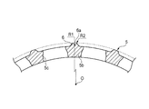
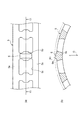
【解決手段】円筒ころ軸受は、外輪と、内輪と、円筒ころと、環状の一対のリム部5a及び一対のリム部5aを軸方向に連結する複数の柱部5bを有し、複数の円筒ころを回転自在に保持する複数のポケット5cを形成する保持器5と、を備える。保持器5は、偶数個の柱部5bによって偶数個のポケット5cを形成し、偶数個の柱部5bのうち、点対称に位置する少なくとも4箇所の柱部5bの外周面又は内周面に、リム部5aの外周面又は内周面より径方向に突出する案内部6を有し、該案内部6により軌道輪案内される。各案内部6の案内面6aは、保持器5の中心Oを曲率中心とした同一半径R1の円弧面をそれぞれ有する。
【選択図】図3
Description
(1) 内周面に外輪軌道面が形成される外輪と、
外周面に内輪軌道面が形成される内輪と、
前記外輪軌道面と前記内輪軌道面との間に転動自在に配置される複数の円筒ころと、
環状の一対のリム部及び該一対のリム部を軸方向に連結する複数の柱部を有し、前記複数の円筒ころを回転自在にそれぞれ保持する複数のポケットを形成する保持器と、
を備える円筒ころ軸受であって、
前記保持器は、偶数個の前記柱部によって偶数個の前記ポケットを形成し、
前記保持器は、前記偶数個の柱部のうち、点対称に位置する少なくとも4箇所の前記柱部の外周面又は内周面に、前記リム部の外周面又は内周面より径方向に突出する案内部を有し、該案内部により軌道輪案内され、
前記各案内部の案内面は、前記保持器の中心を曲率中心とした同一半径の円弧面をそれぞれ有することを特徴とする円筒ころ軸受。
(2) 前記案内部の軸方向幅は、前記ポケットの軸方向幅以下に設定されることを特徴とする(1)に記載の円筒ころ軸受。
(3) 主軸が(1)または(2)に記載の円筒ころ軸受により回動自在に支持されることを特徴とする工作機械用主軸装置。
また、複数個の柱部のうち、各柱部に形成された各案内部の案内面は、保持器の中心を曲率中心とした同一半径の円弧面を有するので、ノギス等を用いて案内面の寸法を測定することができ、保持器の寸法管理を容易に行うことができる。
2 外輪
2a 外輪軌道面
3 内輪
3a 内輪軌道面
4 円筒ころ
5 保持器
5a リム部
5b 柱部
5c ポケット
6 案内部
6a 案内面
6b 凹部
10 主軸装置
11 主軸
Claims (3)
- 内周面に外輪軌道面が形成される外輪と、
外周面に内輪軌道面が形成される内輪と、
前記外輪軌道面と前記内輪軌道面との間に転動自在に配置される複数の円筒ころと、
環状の一対のリム部及び該一対のリム部を軸方向に連結する複数の柱部を有し、前記複数の円筒ころを回転自在にそれぞれ保持する複数のポケットを形成する保持器と、
を備える円筒ころ軸受であって、
前記保持器は、偶数個の前記柱部によって偶数個の前記ポケットを形成し、
前記保持器は、前記偶数個の柱部のうち、点対称に位置する少なくとも4箇所の前記柱部の外周面又は内周面に、前記リム部の外周面又は内周面より径方向に突出する案内部を有し、該案内部により軌道輪案内され、
前記各案内部の案内面は、前記保持器の中心を曲率中心とした同一半径の円弧面をそれぞれ有することを特徴とする円筒ころ軸受。 - 前記案内部の軸方向幅は、前記ポケットの軸方向幅以下に設定されることを特徴とする請求項1に記載の円筒ころ軸受。
- 主軸が請求項1または2に記載の円筒ころ軸受により回動自在に支持されることを特徴とする工作機械用主軸装置。
Priority Applications (1)
| Application Number | Priority Date | Filing Date | Title |
|---|---|---|---|
| JP2010285073A JP5803099B2 (ja) | 2010-12-21 | 2010-12-21 | 円筒ころ軸受及び工作機械用主軸装置 |
Applications Claiming Priority (1)
| Application Number | Priority Date | Filing Date | Title |
|---|---|---|---|
| JP2010285073A JP5803099B2 (ja) | 2010-12-21 | 2010-12-21 | 円筒ころ軸受及び工作機械用主軸装置 |
Publications (2)
| Publication Number | Publication Date |
|---|---|
| JP2012132508A true JP2012132508A (ja) | 2012-07-12 |
| JP5803099B2 JP5803099B2 (ja) | 2015-11-04 |
Family
ID=46648326
Family Applications (1)
| Application Number | Title | Priority Date | Filing Date |
|---|---|---|---|
| JP2010285073A Expired - Fee Related JP5803099B2 (ja) | 2010-12-21 | 2010-12-21 | 円筒ころ軸受及び工作機械用主軸装置 |
Country Status (1)
| Country | Link |
|---|---|
| JP (1) | JP5803099B2 (ja) |
Cited By (3)
| Publication number | Priority date | Publication date | Assignee | Title |
|---|---|---|---|---|
| WO2015119088A1 (ja) * | 2014-02-07 | 2015-08-13 | 株式会社ジェイテクト | 分割保持器及びころ軸受 |
| JP2015148298A (ja) * | 2014-02-07 | 2015-08-20 | 株式会社ジェイテクト | 分割保持器及びころ軸受 |
| US10753402B2 (en) | 2016-12-01 | 2020-08-25 | The Timken Company | Bearing assembly and bearing cage |
Families Citing this family (1)
| Publication number | Priority date | Publication date | Assignee | Title |
|---|---|---|---|---|
| JP7071801B2 (ja) * | 2017-03-03 | 2022-05-19 | Ntn株式会社 | 転がり軸受及びそれを備えた軸受構造 |
Citations (4)
| Publication number | Priority date | Publication date | Assignee | Title |
|---|---|---|---|---|
| JPS55126022U (ja) * | 1979-03-02 | 1980-09-06 | ||
| JPH11166544A (ja) * | 1997-10-01 | 1999-06-22 | Nippon Seiko Kk | ころ軸受用合成樹脂製保持器 |
| JP2002122147A (ja) * | 2000-10-16 | 2002-04-26 | Nsk Ltd | 玉軸受とその製造方法 |
| JP2009299874A (ja) * | 2008-06-17 | 2009-12-24 | Jtekt Corp | 円筒ころ軸受 |
-
2010
- 2010-12-21 JP JP2010285073A patent/JP5803099B2/ja not_active Expired - Fee Related
Patent Citations (4)
| Publication number | Priority date | Publication date | Assignee | Title |
|---|---|---|---|---|
| JPS55126022U (ja) * | 1979-03-02 | 1980-09-06 | ||
| JPH11166544A (ja) * | 1997-10-01 | 1999-06-22 | Nippon Seiko Kk | ころ軸受用合成樹脂製保持器 |
| JP2002122147A (ja) * | 2000-10-16 | 2002-04-26 | Nsk Ltd | 玉軸受とその製造方法 |
| JP2009299874A (ja) * | 2008-06-17 | 2009-12-24 | Jtekt Corp | 円筒ころ軸受 |
Cited By (4)
| Publication number | Priority date | Publication date | Assignee | Title |
|---|---|---|---|---|
| WO2015119088A1 (ja) * | 2014-02-07 | 2015-08-13 | 株式会社ジェイテクト | 分割保持器及びころ軸受 |
| JP2015148298A (ja) * | 2014-02-07 | 2015-08-20 | 株式会社ジェイテクト | 分割保持器及びころ軸受 |
| CN105980724A (zh) * | 2014-02-07 | 2016-09-28 | 株式会社捷太格特 | 分割保持器和滚子轴承 |
| US10753402B2 (en) | 2016-12-01 | 2020-08-25 | The Timken Company | Bearing assembly and bearing cage |
Also Published As
| Publication number | Publication date |
|---|---|
| JP5803099B2 (ja) | 2015-11-04 |
Similar Documents
| Publication | Publication Date | Title |
|---|---|---|
| JP6481717B2 (ja) | 玉軸受、それを用いたモータ及び主軸装置 | |
| WO2011092887A1 (ja) | 中ぐり盤の主軸装置 | |
| JP2008240796A (ja) | シール付きアンギュラ玉軸受及び主軸装置 | |
| JP5803099B2 (ja) | 円筒ころ軸受及び工作機械用主軸装置 | |
| JP5789973B2 (ja) | 円筒ころ軸受及び工作機械用主軸装置 | |
| JP2007010026A (ja) | 円筒ころ軸受及び円筒ころ軸受用保持器 | |
| JP5845652B2 (ja) | 軸受装置及び工作機械用主軸装置 | |
| JP5691490B2 (ja) | 円筒ころ軸受及び工作機械用主軸装置 | |
| JP2009138896A (ja) | 転がり軸受およびその潤滑方法 | |
| JP5982881B2 (ja) | 玉軸受、それを用いたモータ及び主軸装置 | |
| KR20210044827A (ko) | 롤링 베어링 및 이 롤링 베어링을 구비한 스핀들 장치 | |
| JP5644474B2 (ja) | 円筒ころ軸受及び工作機械用主軸装置 | |
| JP2005180629A (ja) | 転がり軸受 | |
| JP2011075093A (ja) | 転がり軸受 | |
| JP6213189B2 (ja) | 軸受装置及びスピンドル装置 | |
| JP6318584B2 (ja) | 軸受装置及びスピンドル装置 | |
| JP2002122149A (ja) | アンギュラ玉軸受およびこれを用いた工作機械 | |
| JP2012072861A (ja) | スピンドル装置 | |
| JP2005299757A (ja) | 転がり軸受 | |
| JP2008240828A (ja) | 転がり軸受のグリース溜り部品およびグリース溜り付き転がり軸受 | |
| JP6354148B2 (ja) | 軸受装置及びスピンドル装置 | |
| JP5353432B2 (ja) | 転がり軸受装置 | |
| JP6221687B2 (ja) | 軸受装置及びスピンドル装置 | |
| JP2009204139A (ja) | 転がり軸受、およびそれを用いた主軸装置 | |
| JP2012082894A (ja) | グリース容器付き転がり軸受装置 |
Legal Events
| Date | Code | Title | Description |
|---|---|---|---|
| A621 | Written request for application examination |
Free format text: JAPANESE INTERMEDIATE CODE: A621 Effective date: 20131126 |
|
| RD04 | Notification of resignation of power of attorney |
Free format text: JAPANESE INTERMEDIATE CODE: A7424 Effective date: 20140210 |
|
| A977 | Report on retrieval |
Free format text: JAPANESE INTERMEDIATE CODE: A971007 Effective date: 20140522 |
|
| A131 | Notification of reasons for refusal |
Free format text: JAPANESE INTERMEDIATE CODE: A131 Effective date: 20140527 |
|
| A521 | Written amendment |
Free format text: JAPANESE INTERMEDIATE CODE: A523 Effective date: 20140716 |
|
| A131 | Notification of reasons for refusal |
Free format text: JAPANESE INTERMEDIATE CODE: A131 Effective date: 20150106 |
|
| RD02 | Notification of acceptance of power of attorney |
Free format text: JAPANESE INTERMEDIATE CODE: A7422 Effective date: 20150126 |
|
| A521 | Written amendment |
Free format text: JAPANESE INTERMEDIATE CODE: A523 Effective date: 20150227 |
|
| TRDD | Decision of grant or rejection written | ||
| A01 | Written decision to grant a patent or to grant a registration (utility model) |
Free format text: JAPANESE INTERMEDIATE CODE: A01 Effective date: 20150804 |
|
| A61 | First payment of annual fees (during grant procedure) |
Free format text: JAPANESE INTERMEDIATE CODE: A61 Effective date: 20150817 |
|
| R150 | Certificate of patent or registration of utility model |
Ref document number: 5803099 Country of ref document: JP Free format text: JAPANESE INTERMEDIATE CODE: R150 |
|
| LAPS | Cancellation because of no payment of annual fees |