JP2012134132A - Flexible heater and method of manufacturing the same - Google Patents
Flexible heater and method of manufacturing the same Download PDFInfo
- Publication number
- JP2012134132A JP2012134132A JP2011256522A JP2011256522A JP2012134132A JP 2012134132 A JP2012134132 A JP 2012134132A JP 2011256522 A JP2011256522 A JP 2011256522A JP 2011256522 A JP2011256522 A JP 2011256522A JP 2012134132 A JP2012134132 A JP 2012134132A
- Authority
- JP
- Japan
- Prior art keywords
- heat
- heating element
- element circuit
- polyimide
- cover member
- Prior art date
- Legal status (The legal status is an assumption and is not a legal conclusion. Google has not performed a legal analysis and makes no representation as to the accuracy of the status listed.)
- Pending
Links
Images




Classifications
-
- H—ELECTRICITY
- H05—ELECTRIC TECHNIQUES NOT OTHERWISE PROVIDED FOR
- H05B—ELECTRIC HEATING; ELECTRIC LIGHT SOURCES NOT OTHERWISE PROVIDED FOR; CIRCUIT ARRANGEMENTS FOR ELECTRIC LIGHT SOURCES, IN GENERAL
- H05B3/00—Ohmic-resistance heating
- H05B3/20—Heating elements having extended surface area substantially in a two-dimensional [2D] plane, e.g. plate-heater
- H05B3/34—Heating elements having extended surface area substantially in a two-dimensional [2D] plane, e.g. plate-heater flexible, e.g. heating nets or webs
-
- H—ELECTRICITY
- H05—ELECTRIC TECHNIQUES NOT OTHERWISE PROVIDED FOR
- H05B—ELECTRIC HEATING; ELECTRIC LIGHT SOURCES NOT OTHERWISE PROVIDED FOR; CIRCUIT ARRANGEMENTS FOR ELECTRIC LIGHT SOURCES, IN GENERAL
- H05B2203/00—Aspects relating to Ohmic resistive heating covered by group H05B3/00
- H05B2203/002—Heaters using a particular layout for the resistive material or resistive elements
- H05B2203/003—Heaters using a particular layout for the resistive material or resistive elements using serpentine layout
-
- H—ELECTRICITY
- H05—ELECTRIC TECHNIQUES NOT OTHERWISE PROVIDED FOR
- H05B—ELECTRIC HEATING; ELECTRIC LIGHT SOURCES NOT OTHERWISE PROVIDED FOR; CIRCUIT ARRANGEMENTS FOR ELECTRIC LIGHT SOURCES, IN GENERAL
- H05B2203/00—Aspects relating to Ohmic resistive heating covered by group H05B3/00
- H05B2203/016—Heaters using particular connecting means
-
- Y—GENERAL TAGGING OF NEW TECHNOLOGICAL DEVELOPMENTS; GENERAL TAGGING OF CROSS-SECTIONAL TECHNOLOGIES SPANNING OVER SEVERAL SECTIONS OF THE IPC; TECHNICAL SUBJECTS COVERED BY FORMER USPC CROSS-REFERENCE ART COLLECTIONS [XRACs] AND DIGESTS
- Y10—TECHNICAL SUBJECTS COVERED BY FORMER USPC
- Y10T—TECHNICAL SUBJECTS COVERED BY FORMER US CLASSIFICATION
- Y10T29/00—Metal working
- Y10T29/49—Method of mechanical manufacture
- Y10T29/49002—Electrical device making
- Y10T29/49117—Conductor or circuit manufacturing
- Y10T29/49124—On flat or curved insulated base, e.g., printed circuit, etc.
- Y10T29/49155—Manufacturing circuit on or in base
Landscapes
- Surface Heating Bodies (AREA)
- Resistance Heating (AREA)
Abstract
Description
本発明は、発熱体回路をポリイミドフィルムで被覆したポリイミドフレキシブルヒーター及びその製造方法に関するものである。 The present invention relates to a polyimide flexible heater in which a heating element circuit is covered with a polyimide film and a method for manufacturing the same.
発熱体回路を高耐熱性ポリイミドフィルムで積層被覆したフレキシブルヒーターについては、特許文献1、2などで既に提案されている。
特許文献1では、熱融着層を有する多層ポリイミドフィルムで熱融着によって被覆されたフレキシブルヒーターが提案されているが、リード線を接合する端子部は被覆されていなかった。特許文献2では、リード線を接合する端子部が被覆されているが、端子部の凹凸を埋めるため、その周辺に熱可塑性ポリイミド樹脂を置いた上で全体を一括で加熱圧着することを特徴としている。この場合、凹凸の充填に用いる樹脂がヒーター回路部まで流れ込み、その結果としてヒーターの耐熱性が損なわれる可能性がある。また、リード線を接合したヒーター全体を300〜450℃に加熱することによって被覆するため、耐熱性の点からリード線として用いることのできる樹脂被覆電線に制約があった。
A flexible heater in which a heating element circuit is laminated and coated with a high heat-resistant polyimide film has already been proposed in
Patent Document 1 proposes a flexible heater that is covered by heat fusion with a multilayer polyimide film having a heat fusion layer, but the terminal portion for joining the lead wires is not covered. In
本発明の目的は、耐熱性に優れ、また、端子部の強度にも優れたフレキシブルヒーター及びその製造方法を提供することにある。 An object of the present invention is to provide a flexible heater excellent in heat resistance and excellent in strength of a terminal portion and a method for producing the same.
本発明は、少なくとも一方の面に熱融着性ポリイミド表面層を有する多層ポリイミドフィルムからなるベース部材と、該ベース部材の前記熱融着性ポリイミド表面層に形成された発熱体回路と、両面に熱融着性ポリイミド表面層を有する多層ポリイミドフィルムからなり、前記発熱体回路を覆う発熱体回路カバー部材と、前記発熱体回路の一対の接続端部に接続された一対のリード線とを備えたフレキシブルヒーターであって、前記発熱体回路カバー部材は、前記接続端部及びその近傍を覆わないように開放部を有し、前記接続端部及びその近傍、並びに前記リード線の前記ベース部材上に位置する部位は、耐熱性接着剤を介して、前記発熱回路カバー部材と別体に構成され、少なくとも一方の面に熱融着性ポリイミド表面層を有する多層ポリイミドフィルムからなる端部カバー部材によって覆われていることを特徴とする。 The present invention provides a base member made of a multilayer polyimide film having a heat-fusible polyimide surface layer on at least one surface, a heating element circuit formed on the heat-fusible polyimide surface layer of the base member, and both surfaces A heating element circuit cover member that covers the heating element circuit and a pair of lead wires connected to a pair of connection ends of the heating element circuit, comprising a multilayer polyimide film having a heat-fusible polyimide surface layer. In the flexible heater, the heating element circuit cover member has an open portion so as not to cover the connection end portion and the vicinity thereof, and the connection end portion and the vicinity thereof, and the lead wire on the base member. The portion to be positioned is configured separately from the heat generating circuit cover member via a heat-resistant adhesive, and has a multilayer poWer having a heat-fusible polyimide surface layer on at least one surface. Characterized in that it is covered by an end cover member formed of an imide film.
本発明のフレキシブルヒーターにおいて、前記端部カバー部材は、前記接続端部に接続されたリード線の表面形状に添って凹部が形成されていることが好ましい。 In the flexible heater of the present invention, it is preferable that the end cover member has a recess formed along the surface shape of the lead wire connected to the connection end.
また、本発明のフレキシブルヒーターにおいて、ベース部材、発熱体回路カバー部材、及び端部カバー部材に用いられる多層ポリイミドフィルムの熱融着性ポリイミド表面層のガラス転移温度が200〜300℃であり、且つ熱融着性ポリイミド表面層を除いたポリイミド層のガラス転移温度が300℃以上であることが好ましい。 In the flexible heater of the present invention, the glass transition temperature of the heat-fusible polyimide surface layer of the multilayer polyimide film used for the base member, the heating element circuit cover member, and the end cover member is 200 to 300 ° C., and The glass transition temperature of the polyimide layer excluding the heat-fusible polyimide surface layer is preferably 300 ° C. or higher.
さらに、本発明のフレキシブルヒーターにおいて、耐熱性接着剤が、少なくとも、ポリイミドシロキサンとエポキシ基を有する化合物とを含有してなる耐熱性接着剤であることが好ましい。 Furthermore, in the flexible heater of the present invention, the heat-resistant adhesive is preferably a heat-resistant adhesive containing at least polyimidesiloxane and a compound having an epoxy group.
また、本発明は、少なくとも一方の面に熱融着性ポリイミド表面層を有する多層ポリイミドフィルムからなるベース部材の該熱融着性ポリイミド表面層に発熱体回路を形成する工程と、両面に熱融着性ポリイミド表面層を有する多層ポリイミドフィルムからなり、前記発熱体回路の接続端部及びその近傍を覆わないように開放部を有する発熱体回路カバー部材で前記発熱体回路を覆う工程と、前記発熱体回路の接続端部にリード線を接続する工程と、耐熱性接着剤を介して、少なくとも一方の面に熱融着性ポリイミド表面層を有する多層ポリイミドフィルムからなり、前記発熱回路カバー部材と別体に構成される端部カバー部材によって、前記接続端部及びその近傍、並びに前記リード線の前記ベース部材上に位置する部位を覆う工程と、を備えることを特徴とするフレキシブルヒーターの製造方法である。 The present invention also includes a step of forming a heating element circuit on the heat-fusible polyimide surface layer of a base member made of a multilayer polyimide film having a heat-fusible polyimide surface layer on at least one surface, and heat fusion on both surfaces. A step of covering the heating element circuit with a heating element circuit cover member comprising a multilayer polyimide film having an adhesive polyimide surface layer and having an open portion so as not to cover the connection end portion of the heating element circuit and the vicinity thereof; A step of connecting a lead wire to the connection end of the body circuit, and a multilayer polyimide film having a heat-fusible polyimide surface layer on at least one surface via a heat-resistant adhesive, and separate from the heating circuit cover member A step of covering the connection end portion and the vicinity thereof and a portion of the lead wire located on the base member by an end cover member configured in a body; Is a manufacturing method of a flexible heater, characterized in that to obtain.
以上のように、本発明によれば、耐熱性に優れ、また、端子部の強度にも優れたフレキシブルヒーター及びその製造方法を提供することができる。さらに、リード線を接合した端子部分を高温に加熱する必要が無いため、比較的耐熱性が低い樹脂被覆電線を用いることが可能となる。 As described above, according to the present invention, it is possible to provide a flexible heater excellent in heat resistance and excellent in strength of a terminal portion and a method for manufacturing the same. Furthermore, since it is not necessary to heat the terminal portion joined with the lead wire to a high temperature, it is possible to use a resin-coated electric wire having relatively low heat resistance.
先ず、本発明に係るフレキシブルヒーターの実施形態について、図1乃至3に基づいて説明する。本実施形態に係るフレキシブルヒーター2は、ベース部材10と、ベース部材10の上面に形成された発熱体回路12と、発熱体回路12を覆う発熱体回路カバー部材14と、発熱体回路12の一対の接続端部12a、12aに端子16、16を介して接続された一対のリード線17、17とを備えている。発熱体回路カバー部材14は、接続端部12a、12a及びその近傍、端子16、16、並びにリード線17、17を覆わないように孔14a、14aを有し、接続端部12a、12a及びその近傍、端子16、16、並びにリード線17、17は、耐熱性接着剤20を介して、発熱回路カバー部材14と別体に構成される端部カバー部材22によって覆われている。
First, an embodiment of a flexible heater according to the present invention will be described with reference to FIGS. The
本実施形態において、ベース部材10及び端部カバー部材22は、少なくとも一方の面が熱融着性ポリイミド表面層を有する多層ポリイミドフィルムから構成されている。また、発熱体回路カバー部材14は、両面に熱融着性ポリイミド表面層を有する多層ポリイミドフィルムから構成されている。本実施形態において、熱融着性ポリイミド表面層を有する多層ポリイミドフィルムは、表面に熱融着性ポリイミド表面層を有する多層のポリイミドフィルムであり、例えば2層あるいは3層構造[熱融着性ポリイミド表面層/ポリイミド層(/熱融着性ポリイミド表面層)]の多層ポリイミドフィルムが挙げられる。このような多層ポリイミドフィルムは、例えば熱融着性ポリイミド表面層を与えるポリイミド前駆体溶液をポリイミド層の少なくとも一方の面、或いは両面に、共押出し成形法によって積層する方法によって得ることができる。
In the present embodiment, the
本実施形態において、熱融着性を有する多層ポリイミドフィルムの熱融着性ポリイミド表面層は、300〜400℃の温度範囲で熱圧着できる熱融着性ポリイミドからなるものが好ましい。好ましくは、熱融着性ポリイミドは、ガラス転移温度が200〜300℃である。 In this embodiment, the heat-fusible polyimide surface layer of the multilayer polyimide film having heat-fusibility is preferably made of a heat-fusible polyimide that can be thermocompression bonded in a temperature range of 300 to 400 ° C. Preferably, the heat-fusible polyimide has a glass transition temperature of 200 to 300 ° C.
熱融着性ポリイミドは、好適には1,3−ビス(4−アミノフェノキシ)ベンゼン(以下、TPE−Rと略記することもある。)と2,3,3’,4’−ビフェニルテトラカルボン酸二無水物(以下、a−BPDAと略記することもある。)とから製造される。また、熱融着性ポリイミドとしては、1,3−ビス(4−アミノフェノキシ)−2,2−ジメチルプロパン(DANPG)と4,4’−オキシジフタル酸二無水物(ODPA)とから製造される。あるいは、4,4’−オキシジフタル酸二無水物(ODPA)およびピロメリット酸二無水物と1,3−ビス(4−アミノフェノキシ)ベンゼンとから製造される。また、1,3−ビス(3−アミノフェノキシ)ベンゼンと3,3’,4,4’−ベンゾフェノンテトラカルボン酸二無水物とから、あるいは3,3’−ジアミノベンゾフェノンおよび1,3−ビス(3−アミノフェノキシ)ベンゼンと3,3’,4,4’−ベンゾフェノンテトラカルボン酸二無水物とから製造される。さらに、テトラカルボン酸成分中、100モル%中の12〜25モル%がピロメリット酸二無水物、5〜15モル%が3,3’,4,4’−ベンゾフェノンテトラカルボン酸二無水物、残部が3,3’,4,4’−ビフェニルテトラカルボン酸二無水物であり、ジアミン成分として1、3−ビス(4−アミノフェノキシ)ベンゼンを必須成分とし、DSC測定によりTgが観測できる熱融着性ポリイミドも好適である。 The heat-fusible polyimide is preferably 1,3-bis (4-aminophenoxy) benzene (hereinafter sometimes abbreviated as TPE-R) and 2,3,3 ′, 4′-biphenyltetracarboxylic. It is produced from an acid dianhydride (hereinafter sometimes abbreviated as a-BPDA). Further, the heat-fusible polyimide is manufactured from 1,3-bis (4-aminophenoxy) -2,2-dimethylpropane (DANPG) and 4,4′-oxydiphthalic dianhydride (ODPA). . Alternatively, it is prepared from 4,4'-oxydiphthalic dianhydride (ODPA) and pyromellitic dianhydride and 1,3-bis (4-aminophenoxy) benzene. Also, from 1,3-bis (3-aminophenoxy) benzene and 3,3 ′, 4,4′-benzophenonetetracarboxylic dianhydride, or from 3,3′-diaminobenzophenone and 1,3-bis ( 3-aminophenoxy) benzene and 3,3 ′, 4,4′-benzophenone tetracarboxylic dianhydride. Further, in the tetracarboxylic acid component, 12 to 25 mol% of 100 mol% is pyromellitic dianhydride, 5 to 15 mol% is 3,3 ′, 4,4′-benzophenone tetracarboxylic dianhydride, The balance is 3,3 ′, 4,4′-biphenyltetracarboxylic dianhydride, 1,3-bis (4-aminophenoxy) benzene is an essential component as a diamine component, and Tg can be observed by DSC measurement A fusible polyimide is also suitable.
この熱融着性ポリイミドは、前記熱融着性を損なわない範囲で他のテトラカルボン酸二無水物、例えば3,3’,4,4’−ビフェニルテトラカルボン酸二無水物、2,2−ビス(3,4−ジカルボキシフェニル)プロパン二無水物などで置き換えられてもよい。 This heat-fusible polyimide can be used in the form of other tetracarboxylic dianhydrides, for example, 3,3 ′, 4,4′-biphenyltetracarboxylic dianhydride, 2,2- It may be replaced with bis (3,4-dicarboxyphenyl) propane dianhydride.
熱融着性ポリイミドの製造方法において、前記各成分と、さらに場合により他のテトラカルボン酸二無水物および他のジアミンとを、有機溶媒中、約100℃以下、特に20〜60℃の温度で反応させてポリアミック酸の溶液とし、このポリアミック酸の溶液をドープ液として使用できる。 In the method for producing a heat-fusible polyimide, the above-mentioned components and, if necessary, other tetracarboxylic dianhydrides and other diamines in an organic solvent at a temperature of about 100 ° C. or less, particularly 20 to 60 ° C. It can be made to react to make a solution of polyamic acid, and this polyamic acid solution can be used as a dope solution.
前記熱融着性ポリイミドの前駆体溶液であるポリアミック酸溶液は、酸成分のモル数がジアミンのモル数に対する比として、好ましくは0.92〜1.1、特に0.98〜1.1、そのなかでも特に0.99〜1.1であるような割合が好ましい。また、ポリアミック酸のゲル化を制限する目的でリン系安定剤、例えば亜リン酸トリフェニル、リン酸トリフェニル等をポリアミック酸重合時に固形分(ポリマー)濃度に対して0.01〜1%の範囲で添加することができる。また、イミド化促進の目的で、溶液中に塩基性有機化合物系触媒を添加することができる。例えば、イミダゾール、2−イミダゾール、1,2−ジメチルイミダゾール、2−フェニルイミダゾールなどをポリアミック酸(固形分)に対して0.01〜20重量%、特に0.5〜10重量%の割合で使用することができる。これらは比較的低温でポリイミドフィルムを形成するため、イミド化が不十分となることを避けるために使用する。また、接着強度の安定化の目的で、熱融着性の芳香族ポリイミド原料ドープに有機アルミニウム化合物、無機アルミニウム化合物または有機錫化合物を添加してもよい。例えば水酸化アルミニウム、アルミニウムトリアセチルアセトナートなどをポリアミック酸(固形分)に対してアルミニウム金属として1ppm以上、特に1〜1000ppmの割合で添加することができる。 The polyamic acid solution which is the precursor solution of the heat-fusible polyimide is preferably 0.92 to 1.1, particularly 0.98 to 1.1, as the ratio of the number of moles of the acid component to the number of moles of the diamine. Among these, a ratio of 0.99 to 1.1 is particularly preferable. Further, for the purpose of limiting the gelation of polyamic acid, a phosphorus stabilizer such as triphenyl phosphite, triphenyl phosphate is 0.01 to 1% of the solid content (polymer) concentration during polyamic acid polymerization. It can be added in a range. For the purpose of promoting imidization, a basic organic compound catalyst can be added to the solution. For example, imidazole, 2-imidazole, 1,2-dimethylimidazole, 2-phenylimidazole, etc. are used in a proportion of 0.01 to 20% by weight, particularly 0.5 to 10% by weight, based on the polyamic acid (solid content). can do. Since these form a polyimide film at a relatively low temperature, they are used to avoid imidation becoming insufficient. Further, for the purpose of stabilizing the adhesive strength, an organoaluminum compound, an inorganic aluminum compound, or an organotin compound may be added to the thermally fusible aromatic polyimide raw material dope. For example, aluminum hydroxide, aluminum triacetylacetonate, or the like can be added in an amount of 1 ppm or more, particularly 1 to 1000 ppm as aluminum metal with respect to polyamic acid (solid content).
前記のポリアミック酸溶液の製造に使用する有機溶媒は、高耐熱性の芳香族ポリイミドおよび熱融着性の芳香族ポリイミドのいずれに対しても、N−メチル−2−ピロリドン、N,N−ジメチルホルムアミド、N,N−ジメチルアセトアミド、N,N−ジエチルアセトアミド、ジメチルスルホキシド、ヘキサメチルホスホルアミド、N−メチルカプロラクタム、クレゾール類などが挙げられる。これらの有機溶媒は単独で用いてもよく、2種以上を併用してもよい。 The organic solvent used for the production of the polyamic acid solution is N-methyl-2-pyrrolidone, N, N-dimethyl for both high heat-resistant aromatic polyimide and heat-fusible aromatic polyimide. Examples include formamide, N, N-dimethylacetamide, N, N-diethylacetamide, dimethyl sulfoxide, hexamethylphosphoramide, N-methylcaprolactam, and cresols. These organic solvents may be used alone or in combination of two or more.
本実施形態において、多層ポリイミドフィルムの熱融着性ポリイミド表面層を除いたポリイミド層を形成するポリイミドは、好適にはガラス転移温度が300℃以上或いはガラス転移温度を示さない高耐熱性ポリイミドであることが好適である。前記高耐熱性ポリイミドは、好適には3,3’,4,4’−ビフェニルテトラカルボン酸二無水物(以下単にs−BPDAと略記することもある。)とパラフェニレンジアミン(以下単にPPDと略記することもある。)と場合によりさらに4,4’−ジアミノジフェニルエーテル(以下単にDADEと略記することもある。)および/またはピロメリット酸二無水物(以下単にPMDAと略記することもある。)とから製造される。この場合PPD/DADE(モル比)は100/0〜85/15であることが好ましい。また、s−BPDA/PMDAは100/0〜50/50であることが好ましい。 In the present embodiment, the polyimide forming the polyimide layer excluding the heat-sealable polyimide surface layer of the multilayer polyimide film is preferably a high heat-resistant polyimide having a glass transition temperature of 300 ° C. or higher or no glass transition temperature. Is preferred. The high heat-resistant polyimide is preferably 3,3 ′, 4,4′-biphenyltetracarboxylic dianhydride (hereinafter sometimes simply referred to as s-BPDA) and paraphenylenediamine (hereinafter simply referred to as PPD). And sometimes 4,4′-diaminodiphenyl ether (hereinafter sometimes abbreviated as DADE) and / or pyromellitic dianhydride (hereinafter simply abbreviated as PMDA). ) And manufactured from. In this case, the PPD / DADE (molar ratio) is preferably 100/0 to 85/15. Moreover, it is preferable that s-BPDA / PMDA is 100 / 0-50 / 50.
また、前記高耐熱性ポリイミドは、ピロメリット酸二無水物とパラフェニレンジアミンおよび4,4’−ジアミノジフェニルエーテルとから製造される。この場合DADE/PPD(モル比)は90/10〜10/90であることが好ましい。 The high heat-resistant polyimide is produced from pyromellitic dianhydride, paraphenylenediamine, and 4,4'-diaminodiphenyl ether. In this case, the DADE / PPD (molar ratio) is preferably 90/10 to 10/90.
さらに、前記高耐熱性ポリイミドは、3,3’,4,4’−ベンゾフェノンテトラカルボン酸二無水物(BTDA)およびピロメリット酸二無水物(PMDA)とパラフェニレンジアミン(PPD)および4,4’−ジアミノジフェニルエーテル(DADE)とから製造される。この場合、酸二無水物中BTDAが20〜90モル%、PMDAが10〜80モル%、ジアミン中PPDが30〜90モル%、DADEが10〜70モル%であることが好ましい。 Further, the high heat-resistant polyimide includes 3,3 ′, 4,4′-benzophenonetetracarboxylic dianhydride (BTDA), pyromellitic dianhydride (PMDA), paraphenylenediamine (PPD), and 4,4. It is produced from '-diaminodiphenyl ether (DADE). In this case, it is preferable that BTDA in acid dianhydride is 20 to 90 mol%, PMDA is 10 to 80 mol%, PPD in diamine is 30 to 90 mol%, and DADE is 10 to 70 mol%.
前記高耐熱性ポリイミドでは、その物性を損なわない範囲で、他の種類の芳香族テトラカルボン酸二無水物や芳香族ジアミン、例えば4,4’−ジアミノジフェニルメタン等を使用してもよい。 In the high heat-resistant polyimide, other types of aromatic tetracarboxylic dianhydrides and aromatic diamines such as 4,4'-diaminodiphenylmethane may be used as long as the physical properties are not impaired.
前記の共押出し−流延製膜法においては、例えば前記高耐熱性ポリイミドの片面あるいは両面に熱融着性ポリイミドの前駆体溶液を共押出して、これをステンレス鏡面、ベルト面等の支持体面上に流延塗布し、100〜300℃で半硬化状態またはそれ以前の乾燥状態とすることが好ましい。この半硬化状態またはそれ以前の状態とは、加熱および/または化学イミド化によって自己支持性の状態にあることを意味する。前記の共押出しは、例えば特開平3−180343号公報(特公平7−102661号公報)に記載の共押出法によって2層あるいは3層の押出し成形用ダイスに供給し、支持体上にキャストしておこなうことができる。 In the coextrusion-casting film forming method, for example, a precursor solution of a heat-fusible polyimide is coextruded on one side or both sides of the high heat resistant polyimide, and this is supported on a support surface such as a stainless steel mirror surface or a belt surface. It is preferable that the film is cast and applied to a semi-cured state or a dried state before that at 100 to 300 ° C. This semi-cured state or an earlier state means that it is in a self-supporting state by heating and / or chemical imidization. The co-extrusion is, for example, supplied to a two-layer or three-layer extrusion die by a co-extrusion method described in JP-A-3-180343 (Japanese Patent Publication No. 7-102661) and cast on a support. Can be done.
前記の高耐熱性ポリイミドの片面あるいは両面に、熱融着性ポリイミドを与えるポリアミック酸溶液を積層して多層フィルム状物を形成して乾燥後、熱融着性ポリイミドのガラス転移温度(Tg)以上で劣化が生じる温度以下の温度、好適には最高加熱温度が375℃以上550℃以下の温度で加熱して乾燥およびイミド化すれば、高耐熱性ポリイミドの片面あるいは両面に熱融着性ポリイミド表面層を有する多層ポリイミドフィルムを好適に得ることができる。 A polyamic acid solution that gives a heat-fusible polyimide is laminated on one or both sides of the high heat-resistant polyimide to form a multilayer film-like material, and then dried, and then the glass transition temperature (Tg) or higher of the heat-fusible polyimide. Heat-bondable polyimide surface on one or both sides of high heat-resistant polyimide by heating at a temperature below the temperature at which deterioration occurs, preferably at a maximum heating temperature of 375 ° C to 550 ° C and drying and imidizing A multilayer polyimide film having a layer can be suitably obtained.
本実施形態において、熱融着性ポリイミド表面層を有する多層ポリイミドフィルムのポリイミド層(基体層)の厚さは約5〜100μm、特に約7〜50μm程度である。また、熱融着性ポリイミド表面層の厚みは1〜10μm、特に2〜5μmが好ましい。1μm未満では熱融着によって良好な接着性能を得ることが難しくなる。一方、10μmを超えると、使用できなくはないが特に効果はなく、むしろ得られるポリイミドヒーターの耐熱性が低下する。 In the present embodiment, the thickness of the polyimide layer (base layer) of the multilayer polyimide film having the heat-fusible polyimide surface layer is about 5 to 100 μm, particularly about 7 to 50 μm. The thickness of the heat-fusible polyimide surface layer is preferably 1 to 10 μm, particularly preferably 2 to 5 μm. If it is less than 1 μm, it is difficult to obtain good adhesion performance by heat fusion. On the other hand, if it exceeds 10 μm, it cannot be used but is not particularly effective, but rather the heat resistance of the resulting polyimide heater is lowered.
そして、熱融着性ポリイミド表面層を有する多層ポリイミドフィルムは、厚みが10〜100μm、特に10〜50μm、その中でも10〜25μmであることが好ましい。10μm未満では作製したフィルムの取り扱いが難しく、100μmより厚くても特に効果はなく、発熱体と加熱圧着して片側の熱融着性多層ポリイミドフィルムによって発熱体の金属を除く空間を充填する際に困難になり不利である。 The multilayer polyimide film having a heat-fusible polyimide surface layer has a thickness of 10 to 100 μm, particularly 10 to 50 μm, and preferably 10 to 25 μm. If it is less than 10 μm, it is difficult to handle the produced film, and even if it is thicker than 100 μm, there is no particular effect, and when the space excluding the metal of the heating element is filled with the heat-bonding multilayer polyimide film on one side by heating and pressing with the heating element. It becomes difficult and disadvantageous.
また、本実施形態において、ベース部材10の上面には発熱体回路12が形成されている。発熱体回路12としては、線状あるいは箔状の金属からなる発熱体が使用される。材質は、ステンレス、ニッケル合金、カンタル、インコネル、鋳鉄などの電気抵抗を有するものが挙げられ、特に比電気抵抗が30×10−6Ωcm以上のものが好ましい。そして、特にステンレス箔又はニッケル合金箔からなる発熱体回路が好適である。また、発熱体回路12には、少なくとも一対の+極用および−極用の接続端部12a、12aが形成されており、これら接続端部12a、12aには、端子16、16を介してリード線17、17が接合される。
In the present embodiment, the
箔で形成された発熱体回路12としては、幅が10μm〜20mm程度のものが好ましい。また、厚みが5〜100μm程度、特に5〜50μm程度のものが好ましい。
The
本実施形態の発熱体回路12は、例えば金属箔をそれ自体公知のエッチング法によって、例えばマスクを金属箔に載せて塩化第二鉄溶液でステンレスのような金属箔をエッチングして、ステンレスなどの金属回路をもつ基板を形成する方法によって得ることができる。このような発熱体回路12では、金属箔間の空間の幅が50μm〜20mm程度の面状のものが好適である。
The
また、本実施形態において、発熱体回路12の上面には、発熱体回路カバー部材14が被膜されている。発熱体回路カバー部材14は、少なくとも一部に表面から裏面に亘って貫通する方形状の孔14a、14aを有し、発熱体回路の接続端部12a、12a及びその近傍、端子16、16、並びにリード線17、17を覆わないように構成されている。この発熱体回路カバー部材14の孔14a、14aによって発熱体回路カバー部材14が覆われなかった部位及びその近傍、すなわち発熱体回路の接続端部12a、12a及びその近傍、端子16、16、並びにリード線17、17のベース部材10上に位置する部位には、方形状に形成された端部カバー部材22が、耐熱性接着剤20を介して覆われている。なお、本実施形態において、発熱体回路カバー部材14の開放部として、孔14a、14aを形成したが、平面方向に開口するように端部に形成しても良い。
In the present embodiment, the heating element
本実施形態においては、このように発熱体回路カバー部材14とは別に端部カバー部材22を設けることによって、発熱体回路の接続端部12a、12a及びその近傍、端子16、16、並びにリード線17、17は、耐熱性接着剤20を介して、端部カバー部材22によって覆われることになる。接続端部12a、12a及びその近傍、端子16、16、並びにリード線17、17を発熱体回路カバー部材14で覆わず、他の発熱体回路12とは別の処理を施すことで、耐熱性接着剤20が発熱体回路12にまで流れ込みヒーターの耐熱性を損ねてしまうという問題を解決できる。
In this embodiment, by providing the
本実施形態において、接続端部12a、12a及びその近傍、端子16、16、並びにリード線17、17と端部カバー部材22とを接着させるのに用いられる耐熱性接着剤20は、耐熱性と接着力に関して要求される特性を満たすものであればよい。特に、各種金属と耐熱性フィルム、シートなどの耐熱性支持材料とを比較的低温で容易に張り合わすことができ、接着・硬化後の高温における高い接着力を有するものであることが好ましい。接着する際の加熱・硬化温度は、140〜300℃であるのが好ましく、特に150〜280℃であるのが好ましい。また、予めシート状物に成形し、被接着物にはさみ込む形態で使用できるものであるのが好ましい。
In this embodiment, the
接続端部12a、12a及びその近傍、並びに端子16、16、リード線17、17及びその近傍を他の発熱体回路12と同様に発熱体回路カバー部材14で覆わず、接続端部12a、12a及びその近傍、端子16、16、並びにリード線17、17を耐熱性接着剤20を用いて端部カバー部材22と接着させることで、発熱体回路カバー部材14で覆う場合よりも低い温度で接着処理を施すことができる。そのため、リード線17、17には、耐熱性が低い樹脂被覆電線を用いることが可能となる。
The
耐熱性接着剤20は少なくとも、ポリイミドシロキサンとエポキシ基を有する化合物とを含有してなる耐熱性接着剤であるのが好ましく、具体的には、ポリイミドシロキサン(a)、エポキシ・ポリオキシアルキレン変性ポリシロキサン(b)、エポキシ基を有する他のエポキシ化合物(c)、及びエポキシ硬化剤(d)を含有してなる接着剤が好ましい。
The heat-
ポリイミドシロキサン(a)は、例えば、芳香族テトラカルボン酸成分と、ジアミノポリシロキサン、及び芳香族ジアミンからなるジアミン成分とを、略等モル使用し、ジアミノポリシロキサンと芳香族ジアミンの使用割合を適宜調整して、有機極性溶媒中で15〜250℃で重合する方法で得ることができる。できるだけ高分子量で、イミド化率が高く、有機極性溶媒に少なくとも3重量%以上、特に5〜40%程度の高濃度で均一に溶解させることができるものが、接着性能のよい接着剤が得られるので好適である。 Polyimide siloxane (a) uses, for example, approximately equimolar amounts of an aromatic tetracarboxylic acid component and a diamine component composed of diaminopolysiloxane and aromatic diamine, and the use ratio of diaminopolysiloxane and aromatic diamine is appropriately determined. It can be obtained by adjusting and polymerizing at 15 to 250 ° C. in an organic polar solvent. Adhesives with good adhesion performance can be obtained with as high a molecular weight as possible, with a high imidization rate, and can be uniformly dissolved in an organic polar solvent at a high concentration of at least 3% by weight, particularly about 5 to 40%. Therefore, it is preferable.
エポキシ・ポリアルキレン変性ポリシロキサン(b)は、ポリシロキサンの末端又は内部に、少なくともエポキシ基を1つ、ポリアルキレン基を1つ有するエポキシ・ポリアルキレン変性ポリシロキサンであればよいが、融点が90℃以下のもの、さらには30℃以下で液状のものが好適に使用される。一般には末端に水酸基、カルボキシル基、又はアミノ基を有する反応性ポリシロキサンオイルと、ビスフェノール型エポキシ樹脂、フェノールノボラック型エポキシ樹脂、グリシジルエーテル型エポキシ樹脂、グリシジルエステル型エポキシ樹脂などのエポキシ化合物及びポリオキシプロピレン、ポリオキシエチレンなどのポリアルキレンとを、80〜140℃程度の温度で反応させることによって得られる。 The epoxy-polyalkylene-modified polysiloxane (b) may be an epoxy-polyalkylene-modified polysiloxane having at least one epoxy group and one polyalkylene group at the terminal or inside of the polysiloxane, but has a melting point of 90. Those having a temperature of not higher than ° C., and those having a liquid temperature of not higher than 30 ° C. are preferably used. In general, a reactive polysiloxane oil having a hydroxyl group, a carboxyl group, or an amino group at the terminal, an epoxy compound such as a bisphenol type epoxy resin, a phenol novolac type epoxy resin, a glycidyl ether type epoxy resin, a glycidyl ester type epoxy resin, or a polyoxy It can be obtained by reacting with a polyalkylene such as propylene and polyoxyethylene at a temperature of about 80 to 140 ° C.
エポキシ基を有する他のエポキシ化合物(c)としては、1個以上のエポキシ基を有するエポキシ化合物、例えばビスフェノールA型やビスフェノールF型のエポキシ樹脂、フェノールノボラック型エポキシ樹脂、アルキル多価フエノール型エポキシ樹脂、多官能型エポキシ樹脂、グリシジルエーテル型エポキシ樹脂、グリシジルエステル型エポキシ樹脂、グリシジルアミン型エポキシ樹脂などが単独で又複数で使用される。エポキシ化合物は、その融点が高すぎると、未硬化状態の接着剤の軟化点が高くなるので、融点が90℃以下、好ましくは0〜80℃のもの、さらには30℃以下の温度で液状のものが好適である。 As the other epoxy compound (c) having an epoxy group, an epoxy compound having one or more epoxy groups, for example, a bisphenol A type or bisphenol F type epoxy resin, a phenol novolac type epoxy resin, or an alkyl polyvalent phenol type epoxy resin Polyfunctional type epoxy resins, glycidyl ether type epoxy resins, glycidyl ester type epoxy resins, glycidyl amine type epoxy resins and the like may be used alone or in combination. When the melting point of the epoxy compound is too high, the softening point of the uncured adhesive is increased, so that the melting point is 90 ° C. or less, preferably 0 to 80 ° C., and further liquid at a temperature of 30 ° C. or less. Those are preferred.
また、エポキシ硬化剤(d)としては、それ自体公知の硬化剤、例えばイミダゾール類、第3級アミン類、トリフェニルフォスフィン類などの硬化触媒、ジシアンジアミド類、ヒドラジン類、芳香族ジアミン類、水酸基を有するフェノールノボラック型硬化剤などの重付加型硬化剤、有機過酸化物などを挙げることができ、これらは公知の硬化促進剤とともに使用することができる。 As the epoxy curing agent (d), a curing agent known per se, for example, a curing catalyst such as imidazoles, tertiary amines and triphenylphosphine, dicyandiamides, hydrazines, aromatic diamines, hydroxyl groups Examples thereof include polyaddition type curing agents such as phenol novolac type curing agents, organic peroxides, and the like, which can be used together with known curing accelerators.
これらの成分を有機溶媒中で混合することにより接着剤の溶液組成物を得ることができ、さらに、金属箔や芳香族ポリイミドフィルムなどの耐熱性フィルム、ポリエステル、ポリエチレンなどの熱可塑性フィルムの面上にこの溶液組成物を塗布し、接着剤が硬化しない温度で乾燥して溶媒を1重量%以下、特には0.5重量%以下にまで除去し、箔やフィルムから接着剤を剥がして取り出す方法で、未硬化状態の接着剤の薄膜シート(厚さ:約1〜200μm)にすることができる。 By mixing these components in an organic solvent, an adhesive solution composition can be obtained. Furthermore, on the surface of a heat-resistant film such as a metal foil or an aromatic polyimide film, or a thermoplastic film such as polyester or polyethylene. The solution composition is applied to the substrate, dried at a temperature at which the adhesive is not cured, the solvent is removed to 1% by weight or less, particularly 0.5% by weight or less, and the adhesive is removed from the foil or film. Thus, an uncured adhesive thin film sheet (thickness: about 1 to 200 μm) can be formed.
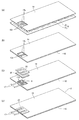
次に、本実施形態に係るフレキシブルヒーター2の製造方法について、図4に基づいて説明する。本実施形態に係るフレキシブルヒーター2は、ベース部材10の熱融着性ポリイミド表面層に発熱体回路12を形成する工程(1)と、発熱体回路12の接続端部12a、12a及びその近傍を覆わないように孔14a、14aを有する発熱体回路カバー部材14で発熱体回路12を覆う工程(2)と、端子16、16及びリード線17、17を発熱体回路12の接続端部12a、12aに接続する工程(3)と、耐熱性接着剤20を介して、発熱回路カバー部材14と別体に構成される端部カバー部材22によって接続端部12a、12a及びその近傍、端子16、16、並びにリード線17、17を覆う工程(4)とによって製造することができる。
Next, the manufacturing method of the
(1)の工程では、まず発熱体回路12となる金属箔とベース部材10を構成する多層ポリイミドフィルムとを熱融着させて金属箔と多層ポリイミドフィルムとからなる積層体を形成する。
In the step (1), first, a metal foil that forms the
金属箔と多層ポリイミドフィルムとの熱融着は、従来公知の方法、例えば熱プレス法が好適に採用できる。熱プレスの温度は、多層ポリイミドの熱融着ポリイミド表面層が熱溶融するのに十分な温度であればよく、熱融着ポリイミド表面層のガラス転移温度が200〜300℃の場合、250〜450℃が好ましく、300〜400℃がより好ましい。また圧力は、接着性を十分に発現する程度であれば特に限定はないが、例えば0.1〜100MPa好ましくは0.1〜50MPaである。また、熱プレスに際しては、気泡等が残留することを防ぐ目的で、減圧下で行うことが好適である。 For heat fusion between the metal foil and the multilayer polyimide film, a conventionally known method such as a hot press method can be suitably employed. The temperature of the heat press may be a temperature sufficient to heat-melt the heat-bonded polyimide surface layer of the multilayer polyimide. When the glass transition temperature of the heat-bonded polyimide surface layer is 200 to 300 ° C., 250 to 450 ° C is preferred, and 300-400 ° C is more preferred. The pressure is not particularly limited as long as the adhesiveness is sufficiently exhibited, but is, for example, 0.1 to 100 MPa, preferably 0.1 to 50 MPa. The hot pressing is preferably performed under reduced pressure for the purpose of preventing bubbles and the like from remaining.
そして、この金属箔を公知の方法、例えば塩化第二鉄溶液を用いるエッチング法によって、エッチングすることで、ベース部材10上に所定の発熱体回路12を容易に形成することができる。
A predetermined
(2)の工程は、図4A、Bに示すように、発熱体回路12の接続端部12a、12a及びその近傍を覆わないように孔14a、14aを有する発熱体回路カバー部材14で、ベース部材10上に形成された発熱体回路12を覆う工程であり、(1)の工程の熱プレスと同様の条件で熱融着することで行うことができる。特に、熱プレスの温度を熱融着性ポリイミド表面層を除いたポリイミド層のガラス転移温度以上の温度とすることでより密着性が高くなり、好ましい。例えば、温度300〜400℃、圧力0.1〜50MPa、減圧下で行うことが好適である。
As shown in FIGS. 4A and 4B, the process (2) is performed with a heating element
(3)の工程は、端子16、16を介してリード線17、17を発熱体回路12の接続端部12a、12aに接続する工程であり、十分な接続を行うことができるなら、従来公知のいずれの方法を採用しても良いが、溶接法によって好適に行うことができる。また、端子16、16の平坦性を保つためにリード線の先端17a、17aに溶接法により金属板からなる端子板を溶接し、その端子板とパラレル溶接で発熱体回路の接続端部12a、12aに接合することが好ましい。
The step (3) is a step of connecting the
(4)の工程は、図4C、Dに示すように、耐熱性接着剤20を介して、発熱回路カバー部材14と別体に構成される端部カバー部材22によって、接続端部12a、12a及びその近傍、端子16、16、並びにリード線17、17を覆う工程である。(4)の工程では、接続端部12a、12a及びその近傍、端子16、16、並びにリード線17、17を耐熱性接着剤20を介して端部カバー部材22である多層ポリイミドフィルムで覆うため、(1)の工程より低い温度条件で熱融着できる。熱プレスの条件は耐熱性接着剤20が接着・硬化する温度であればよく、140〜300℃が好ましい。また圧力は0.1〜50MPaであり、減圧下で行うことが好適である。耐熱性接着剤20として用いられる耐熱性接着剤フィルムの量と大きさは、リード線17、17が接合された端子16、16の周辺の空隙が十分に充填されるように適宜選定されるべきである。また、耐熱性接着剤20と同時に端部カバー部材22で接続端部12a、12a及びその近傍、端子16、16、並びにリード線17、17を覆うようにする。接続端部12a、12a及びその近傍、端子16、16、並びにリード線17、17とその他の部分との段差を調製してより均一に圧力が加わるように、熱融着に際して好ましくは上に例えばシリコーンゴムシートのような耐熱性と柔軟性とを合わせ有するクッション材を用いることにより、得られるフレキシブルヒーターのリード線の変形率を良好にできるので好ましい。
As shown in FIGS. 4C and D, the step (4) is performed by connecting the
また、(4)の工程を行う際、図4Cに示すように、接続端部12a、12a及びその近傍、端子16、16、並びにリード線17、17を覆う端部カバー部材22である多層ポリイミドフィルムを、端子16、16及びリード線17、17をかたどった凹形状にあらかじめ成形しておくことが好ましい。この場合、端子16、16及びリード線17、17をかたどった凸の金型を用い、温度150〜350℃、圧力0.1〜50MPaで熱プレスを行うのが好適である。
Moreover, when performing the process of (4), as shown to FIG. 4C, the multilayer polyimide which is the edge
以上、本発明の実施形態を説明したが、これらの実施形態は、例として提示したものであり、発明の範囲を限定することは意図していない。これらの実施形態は、その他の様々な形態で実施されることが可能である。 As mentioned above, although embodiment of this invention was described, these embodiment is shown as an example and is not intending limiting the range of invention. These embodiments can be implemented in various other forms.
本発明では、発熱体回路のリード線が接合された接続端部の周辺の空隙は、前記耐熱性接着剤によって充填されている。すなわち、リード線が接合された接続端部は、多層ポリイミドフィルムの熱融着性ポリイミド表面層、あるいは接続端部に配置された耐熱性接着剤を介して多層ポリイミドフィルムと接着し、更に接続端部の周辺の空隙が耐熱性接着剤によって充填されている。さらに、発熱体回路全体はあらかじめ多層ポリイミドフィルムによって被覆され且つ密に一体化された構造になっているため、耐熱性接着剤が発熱回路部に流れ込むことがなく、高温条件で長期間使用しても、ヒーター自身はもちろんリード線が接合された端子部も含めて極めて長期間安定して使用することができる。 In the present invention, the gap around the connection end where the lead wire of the heating element circuit is joined is filled with the heat-resistant adhesive. That is, the connection end portion to which the lead wire is bonded is bonded to the multilayer polyimide film via a heat-sealable polyimide surface layer of the multilayer polyimide film or a heat-resistant adhesive disposed on the connection end portion. The space around the part is filled with a heat-resistant adhesive. Furthermore, since the entire heating element circuit is covered with a multilayer polyimide film in advance and has a tightly integrated structure, the heat-resistant adhesive does not flow into the heating circuit part, and it can be used for a long time under high temperature conditions. However, the heater itself can be used stably for a very long time including the terminal part to which the lead wire is bonded as well as the heater.
さらに、接続端部及びその近傍の被覆を発熱体回路本体とは別に行うことにより、熱プレスの温度を低く抑えることが可能となり、リード線の被覆に要求される耐熱性が低くなるため、リード線の選択の幅が広くなる。 Furthermore, by performing the coating of the connection end and the vicinity thereof separately from the heating element circuit body, it becomes possible to keep the temperature of the heat press low, and the heat resistance required for the coating of the lead wire is reduced. A wider range of line selection.
本発明のフレキシブルヒーターは、耐熱性試験で引っ張り強度の半減する時間が20000時間を確保できる温度である長期安全性が確保される温度が約250℃以上である。 In the flexible heater of the present invention, the temperature at which long-term safety, which is a temperature at which the time for halving the tensile strength by half in the heat resistance test can be secured, is about 250 ° C. or more.
次に、実施例により、本発明を更に具体的に説明するが、本発明はこれらの実施例に限定されるものではない。
まず、本実施例の各測定は、以下の通りに行なった。
(1)ガラス転移温度の測定
セイコーインスツルメント社製SSC5200 DSC320によって、窒素中20℃/分で昇温して示差熱を測定して求めた。
(2)90°ピール強度の測定
IPC−FC−241Bに準拠した。
(3)直流抵抗測定
MIL−STD−202G 試験方法303に準拠した。
(4)絶縁抵抗測定
MIL−STD−202G 試験方法302に準拠した。
印加電圧;500VDC
印加時間;1分
(5)耐電圧測定
MIL−STD−202G 試験方法301に準拠した。
印加電圧;1000VDC
印加時間;1分
(6)端子強度試験
ヒーターの端子部と反対側の端を引張り試験機の上部チャックに固定し、またリード線を下部チャックに固定して2mm/分の速度で引張り1.4kgの荷重のところで10秒間ホールドした後、引張り試験機からヒーターを外す。
(7)耐湿試験
ヒーターを40℃、相対湿度90%に保った恒温恒湿槽中に入れ、90時間放置する。
(8)熱衝撃試験A
−65℃と175℃の範囲で熱衝撃サイクルを100回負荷した。
(9)熱衝撃試験B
ヒーターを−65℃に保った恒温槽中に入れ、1時間放置した後ヒーターに28Vの電圧を印加し温度上昇した。ヒーターの表面温度が175℃に達した時点で電圧の印加を止めた。この操作を100回繰り返した。
(10)寿命試験
ヒーターを−65℃に保った恒温槽中に入れ、1時間放置した後ヒーターに28Vの電圧を印加し温度上昇した。ヒーターの表面温度が120℃に達した時点で電圧の印加を止めた。この操作を20000回繰り返した。
(11)高温放置試験
高温試験1
ヒーターを200℃に保った恒温槽中に入れ、30時間放置した。
高温試験2
ヒーターを175℃に保った恒温槽中に入れ、1000時間放置した。
EXAMPLES Next, although an Example demonstrates this invention further more concretely, this invention is not limited to these Examples.
First, each measurement in this example was performed as follows.
(1) Measurement of glass transition temperature The glass transition temperature was determined by measuring the differential heat by raising the temperature at 20 ° C./min in nitrogen using SSC5200 DSC320 manufactured by Seiko Instruments Inc.
(2) Measurement of 90 ° peel strength It was based on IPC-FC-241B.
(3) DC resistance measurement MIL-STD-202G The test method 303 was followed.
(4) Insulation resistance measurement MIL-STD-202G The test method 302 was followed.
Applied voltage: 500VDC
Application time: 1 minute (5) Dielectric strength measurement MIL-STD-202G Test method 301 was applied.
Applied voltage: 1000 VDC
Application time: 1 minute (6) Terminal strength test The end opposite to the heater terminal is fixed to the upper chuck of the tensile tester, and the lead wire is fixed to the lower chuck and pulled at a rate of 2 mm / min. After holding for 10 seconds at a load of 4 kg, remove the heater from the tensile tester.
(7) Humidity resistance test The heater is placed in a constant temperature and humidity chamber maintained at 40 ° C. and 90% relative humidity and left for 90 hours.
(8) Thermal shock test A
The thermal shock cycle was loaded 100 times in the range of −65 ° C. and 175 ° C.
(9) Thermal shock test B
The heater was placed in a thermostatic bath maintained at −65 ° C. and left for 1 hour, and then a voltage of 28 V was applied to the heater to raise the temperature. When the surface temperature of the heater reached 175 ° C., voltage application was stopped. This operation was repeated 100 times.
(10) Life test The heater was placed in a thermostatic chamber maintained at -65 ° C and left for 1 hour, and then a voltage of 28 V was applied to the heater to raise the temperature. When the surface temperature of the heater reached 120 ° C., voltage application was stopped. This operation was repeated 20000 times.
(11) High temperature storage test High temperature test 1
The heater was placed in a thermostat kept at 200 ° C. and left for 30 hours.
The heater was placed in a thermostatic bath maintained at 175 ° C. and left for 1000 hours.
実施例1
(シート材の作製)
ベース部材10として、幅及び長さが100mmで厚みが50μmである、フィルムの両側に熱融着層を持つポリイミドフィルム(宇部興産株式会社製ユーピレックス−VT 熱融着層のポリイミドのガラス転移温度240℃)を用い、そこに幅及び長さが100mmで厚みが40μmであるニッケル−クロム合金(株式会社住友金属製)を重ね、真空プレスを用いて真空下330℃で5分間、5MPaの圧力で加圧して、ポリイミドフィルムと金属箔を貼り合わせたシート材を作製した。このシート材の90°ピール強度は、600g/cmであった。
Example 1
(Production of sheet material)
The
(発熱体回路の形成)
前記シート材の金属箔面に感光性ドライフィルムを貼りあわせ、フォトマスクを介して紫外線露光し、アルカリ現像後塩化第二鉄溶液でエッチング及びアルカリ溶液でドライフィルムを除去し、図5のような幅が76.2mm、長さが76.2mmの発熱体回路12を形成した回路基板8を得た。
(Formation of heating element circuit)
A photosensitive dry film is attached to the metal foil surface of the sheet material, exposed to ultraviolet light through a photomask, etched with an alkali solution after etching with an alkali solution, and removed with an alkaline solution, as shown in FIG. A
(回路基板の被覆)
発熱体回路カバー部材14として、フィルムの両側に熱融着層を持つポリイミドフィルム(宇部興産株式会社製ユーピレックス−VT 熱融着層のポリイミドのガラス転移温度240℃)を前記シート材と同様な幅、長さにカットし、更に前記発熱体回路の接続端部12a、12a及びその近傍に相当する部分を、幅4mm、長さ6mmで抜き取った。このフィルムを前記回路基板8の回路形成面に、接続端部12a、12a及びその近傍とフィルムの抜き取り部分が一致するように重ね、図6のように、上面にポリイミドフィルム32、フッ素樹脂板34、ポリイミドフィルム32、ステンレス板30を積層し、下面にポリイミドフィルム32、ステンレス板30を積層し、真空プレスを用いて真空下330℃で5分間、5MPaの圧力で加圧し、発熱体回路カバー部材フィルム14を前記回路基板8と熱融着させて回路の被覆を行った。
(Circuit board coating)
As the heating element
(リード線の装着)
長さ300mmのリード線(潤工社製M81381/17−26)の被覆樹脂を剥がした部分17aと、幅が2.5mm、長さが5mmで、厚みが0.1mmのニッケル−コバルト合金(株式会社ニラコ製コバール)の全面に1.8μmの金メッキを施した端子板16とを、図7のように溶接で接合した。次にリード線17、17を接合した端子板16、16を図1と同様に溶接で回路基板8の接続端部12a、12aに接合した。
(Lead wire attachment)
A
(端子部カバーの作製)
50μmのポリイミドフィルムを幅12mm、長さ18mmに切り出し、端子の形状をかたどった凸の金型に置き、プレス(神藤金属工業所株式会社製圧縮成型機YSR−10)に投入し、350℃、5MPaの圧力で5分加圧して、端子板16、16及びリード線17、17の形状をかたどった端部カバー用ポリイミドフィルム22を得た。
(Preparation of terminal cover)
A polyimide film of 50 μm was cut into a width of 12 mm and a length of 18 mm, placed in a convex mold shaped like a terminal, put into a press (compression molding machine YSR-10 manufactured by Shinto Metal Industry Co., Ltd.), 350 ° C., Pressure was applied at a pressure of 5 MPa for 5 minutes to obtain an end
(端子部周辺の被覆)
リード線を接合した回路基板8の接続端部12a、12a及びその近傍に、幅12mm、長さ18mmに切り出した接着剤シート20(宇部興産株式会社製ユピタイトUPA−N221C)2枚を置き更にその接着剤シート20の上に前記端部カバー用ポリイミドフィルム22を1枚置いた。そして、クッション材として厚みが1mmのシリコーンゴムシート36を用いて図8のように上面にポリイミドフィルム32、シリコーンゴムシート36、ポリイミドフィルム32、ステンレス板30を積層し、下面にポリイミドフィルム32、ステンレス板30を積層した後、プレス(神藤金属工業所株式会社製圧縮成型機YSR−10)に投入し、250℃、5MPaの圧力で5分加圧して端子部の被覆を行い、フレキシブルヒーターを完成させた。直流抵抗値は設計図面の±10%以内であり、絶縁抵抗は、500MΩ以上であり、絶縁破壊も見られなかった。
(Coating around terminal area)
Two adhesive sheets 20 (Upitite UPA-N221C manufactured by Ube Industries, Ltd.) cut out to a width of 12 mm and a length of 18 mm are placed at and near the
このヒーターについて端子強度試験を実施した後、直流抵抗値を測定したところ設計図面の±10%以内であり、高温試験1を実施した後の直流抵抗は設計図面の±10%以内であり、絶縁抵抗は1000MΩであり、耐電圧後の絶縁破壊も見られなかった。
また、このヒーターについて耐湿試験、熱衝撃試験A、熱衝撃試験B及び高温試験2を実施した後の直流抵抗は設計図面の±10%以内であり、絶縁抵抗は500MΩ以上であり、耐電圧後の絶縁破壊も見られなかった。結果を表1に示す。
After the terminal strength test was performed on this heater, the DC resistance value was measured to be within ± 10% of the design drawing. The DC resistance after performing the high temperature test 1 was within ± 10% of the design drawing, and was insulated. The resistance was 1000 MΩ, and no dielectric breakdown was observed after withstand voltage.
In addition, the DC resistance after performing the moisture resistance test, thermal shock test A, thermal shock test B and
実施例2及び3
接続端部12a、12a及びその近傍の被覆をそれぞれ240℃及び260℃で行った以外は実施例1と同様に行った。結果を表1に示す。
Examples 2 and 3
The

2 フレキシブルヒーター
10 ベース部材
12 発熱体回路
12a 接続端部
14 発熱体回路カバー部材
14a 孔(開放部)
16 端子
17 リード線
20 耐熱性接着剤
22 端部カバー部材
2
16
Claims (5)
該ベース部材の前記熱融着性ポリイミド表面層に形成された発熱体回路と、
両面に熱融着性ポリイミド表面層を有する多層ポリイミドフィルムからなり、前記発熱体回路を覆う発熱体回路カバー部材と、
前記発熱体回路の一対の接続端部に接続された一対のリード線とを備えたフレキシブルヒーターであって、
前記発熱体回路カバー部材は、前記接続端部及びその近傍を覆わないように開放部を有し、
前記接続端部及びその近傍、並びに前記リード線の前記ベース部材上に位置する部位は、耐熱性接着剤を介して、前記発熱回路カバー部材と別体に構成され、少なくとも一方の面に熱融着性ポリイミド表面層を有する多層ポリイミドフィルムからなる端部カバー部材によって覆われていることを特徴とするフレキシブルヒーター。 A base member made of a multilayer polyimide film having a heat-fusible polyimide surface layer on at least one surface;
A heating element circuit formed on the heat-fusible polyimide surface layer of the base member;
A heating element circuit cover member for covering the heating element circuit, comprising a multilayer polyimide film having a heat-sealable polyimide surface layer on both sides;
A flexible heater comprising a pair of lead wires connected to a pair of connection ends of the heating element circuit,
The heating element circuit cover member has an open portion so as not to cover the connection end portion and the vicinity thereof,
The connection end portion and the vicinity thereof, and the portion of the lead wire located on the base member are configured separately from the heat generating circuit cover member via a heat-resistant adhesive, and are thermally fused to at least one surface. A flexible heater characterized by being covered with an end cover member made of a multilayer polyimide film having an adhesive polyimide surface layer.
両面に熱融着性ポリイミド表面層を有する多層ポリイミドフィルムからなり、前記発熱体回路の接続端部及びその近傍を覆わないように開放部を有する発熱体回路カバー部材で前記発熱体回路を覆う工程と、
前記発熱体回路の接続端部にリード線を接続する工程と、
耐熱性接着剤を介して、少なくとも一方の面に熱融着性ポリイミド表面層を有する多層ポリイミドフィルムからなり、前記発熱回路カバー部材と別体に構成される端部カバー部材によって、前記接続端部及びその近傍、並びに前記リード線の前記ベース部材上に位置する部位を覆う工程と、
を備えることを特徴とするフレキシブルヒーターの製造方法。
Forming a heating element circuit on the heat-fusible polyimide surface layer of the base member comprising a multilayer polyimide film having a heat-fusible polyimide surface layer on at least one surface;
A step of covering the heating element circuit with a heating element circuit cover member comprising a multilayer polyimide film having a heat-sealable polyimide surface layer on both sides and having an open portion so as not to cover the connection end portion of the heating element circuit and the vicinity thereof When,
Connecting a lead wire to the connection end of the heating element circuit;
Through the heat-resistant adhesive, the connection end portion is composed of a multi-layer polyimide film having a heat-fusible polyimide surface layer on at least one surface, and is configured separately from the heat generating circuit cover member. And the vicinity thereof, and a step of covering the portion of the lead wire located on the base member;
A method for producing a flexible heater, comprising:
Priority Applications (1)
| Application Number | Priority Date | Filing Date | Title |
|---|---|---|---|
| JP2011256522A JP2012134132A (en) | 2010-12-02 | 2011-11-24 | Flexible heater and method of manufacturing the same |
Applications Claiming Priority (3)
| Application Number | Priority Date | Filing Date | Title |
|---|---|---|---|
| JP2010269660 | 2010-12-02 | ||
| JP2010269660 | 2010-12-02 | ||
| JP2011256522A JP2012134132A (en) | 2010-12-02 | 2011-11-24 | Flexible heater and method of manufacturing the same |
Publications (1)
| Publication Number | Publication Date |
|---|---|
| JP2012134132A true JP2012134132A (en) | 2012-07-12 |
Family
ID=45098929
Family Applications (1)
| Application Number | Title | Priority Date | Filing Date |
|---|---|---|---|
| JP2011256522A Pending JP2012134132A (en) | 2010-12-02 | 2011-11-24 | Flexible heater and method of manufacturing the same |
Country Status (3)
| Country | Link |
|---|---|
| US (1) | US20120138595A1 (en) |
| EP (1) | EP2461644B1 (en) |
| JP (1) | JP2012134132A (en) |
Families Citing this family (25)
| Publication number | Priority date | Publication date | Assignee | Title |
|---|---|---|---|---|
| CN103889079B (en) * | 2012-12-20 | 2016-03-09 | 李水波 | Heating plate |
| EP2779784A1 (en) | 2013-03-14 | 2014-09-17 | Shui-Po Lee | Heating plate |
| EP3622993B8 (en) * | 2013-09-13 | 2021-08-25 | Fisher & Paykel Healthcare Limited | Heater base having a guard to control the movement of a humidification chamber |
| EP3130196A4 (en) | 2014-04-10 | 2017-12-06 | Metis Design Corporation | Multifunctional assemblies |
| RU2602799C2 (en) * | 2014-04-23 | 2016-11-20 | Открытое акционерное общество "Информационные спутниковые системы" имени академика М.Ф. Решетнева" | Method of producing flexible-flat electric heater |
| US9565918B2 (en) * | 2014-06-19 | 2017-02-14 | Elc Management Llc | Heating system for single-use packettes |
| US9560907B2 (en) * | 2014-06-19 | 2017-02-07 | Elc Management Llc | Heating system for a cosmetic mask |
| RU2613497C2 (en) * | 2014-07-24 | 2017-03-16 | Открытое акционерное общество "Информационные спутниковые системы имени академика М.Ф. Решетнёва" | Flexible electric heater |
| RU2597836C2 (en) * | 2014-07-24 | 2016-09-20 | Открытое акционерное общество "Информационные спутниковые системы" имени академика М.Ф. Решетнёва" | Method of producing flexible electric heater |
| TWI691399B (en) * | 2015-03-31 | 2020-04-21 | 美商羅傑斯公司 | Substrates, laminates, and components for flexible heaters, flexible heaters, and methods of manufacturing the same |
| CN109417834B (en) * | 2016-07-22 | 2022-04-12 | E.I.内穆尔杜邦公司 | Film heating device |
| CN109561526B (en) * | 2017-09-26 | 2023-04-25 | 杜邦电子公司 | Heating element and heating device |
| WO2019188575A1 (en) * | 2018-03-26 | 2019-10-03 | 株式会社トッパンインフォメディア | Film heater |
| FR3088609B1 (en) * | 2018-11-16 | 2020-11-06 | Plastic Omnium Cie | BODYWORK PART FEATURING A HEATED FILM |
| KR102278775B1 (en) * | 2019-05-10 | 2021-07-19 | (주) 래트론 | Film-type heater with 3d shape-shifting capability and manufacturing method |
| JP2022546680A (en) * | 2019-09-06 | 2022-11-07 | ジェイティー インターナショナル エス.エイ. | thin film heater |
| KR102889862B1 (en) | 2019-09-06 | 2025-11-21 | 제이티 인터내셔널 소시에떼 아노님 | heater assembly |
| CN110597013A (en) * | 2019-09-18 | 2019-12-20 | 北京自动化控制设备研究所 | Flexible micro heater and its processing method |
| RU2726182C1 (en) * | 2019-10-07 | 2020-07-09 | Акционерное общество "Научно-исследовательский институт электромеханики" (АО "НИИЭМ") | Method of manufacturing flexible heat-resistant electric heaters |
| RU2721624C1 (en) * | 2019-11-11 | 2020-05-21 | Акционерное общество «Информационные спутниковые системы» имени академика М.Ф.Решетнёва» | Method for manufacture of flexible-flat electric heater |
| CN111053298B (en) * | 2019-12-20 | 2022-03-15 | 深圳麦克韦尔科技有限公司 | Flexible heating element and manufacturing method thereof, flexible heating assembly and aerosol generator |
| RU2762623C1 (en) * | 2021-06-15 | 2021-12-21 | Акционерное общество «Информационные спутниковые системы» имени академика М.Ф.Решетнёва» | Radiation flexible-flat electric heater |
| FR3131171A1 (en) * | 2021-12-16 | 2023-06-23 | Valeo Systemes Thermiques | Heating device for vehicle interior |
| FR3151962A1 (en) * | 2023-08-03 | 2025-02-07 | Valeo Systemes Thermiques | HEATING STRUCTURE INTENDED TO BE INSTALLED INSIDE A VEHICLE PASSENGER COMPARTMENT |
| CN220823307U (en) * | 2023-08-04 | 2024-04-19 | 讯凯国际股份有限公司 | Heating components |
Citations (8)
| Publication number | Priority date | Publication date | Assignee | Title |
|---|---|---|---|---|
| JPS49142650U (en) * | 1973-04-02 | 1974-12-09 | ||
| JPS54121439A (en) * | 1978-03-10 | 1979-09-20 | Mcmullan James P | Heater structure of electric blanket |
| JPS6476694A (en) * | 1987-09-16 | 1989-03-22 | Hitachi Cable | Sheet heater |
| US5472539A (en) * | 1994-06-06 | 1995-12-05 | General Electric Company | Methods for forming and positioning moldable permanent magnets on electromagnetically actuated microfabricated components |
| JP2001015254A (en) * | 1999-07-02 | 2001-01-19 | Ube Ind Ltd | Tape-shaped heater and method of manufacturing the same |
| JP2003031345A (en) * | 2001-07-17 | 2003-01-31 | Yukio Shiroo | Surface heating element |
| JP2004355882A (en) * | 2003-05-28 | 2004-12-16 | Ube Ind Ltd | Polyimide heater |
| JP2008123869A (en) * | 2006-11-13 | 2008-05-29 | Ube Ind Ltd | Flexible heater and manufacturing method thereof |
Family Cites Families (17)
| Publication number | Priority date | Publication date | Assignee | Title |
|---|---|---|---|---|
| US2884509A (en) * | 1957-03-05 | 1959-04-28 | Electrofilm Inc | Heating element containing a conductive mesh |
| US3781514A (en) * | 1969-05-23 | 1973-12-25 | Uniroyal Inc | Electrically heated glove with a flexible lattice heating structure |
| US3790753A (en) * | 1971-12-01 | 1974-02-05 | Safeway Products Inc | Water bed heater |
| US4197449A (en) * | 1978-07-05 | 1980-04-08 | Springfield Wire Inc. | Flexible electrical heater |
| US4270040A (en) * | 1979-10-19 | 1981-05-26 | Mcmullan James P | Heater with reinforcing strate |
| US4468557A (en) * | 1983-02-03 | 1984-08-28 | Bylin Heating Systems, Inc. | Conformable electric heating apparatus |
| US4797536A (en) * | 1986-03-31 | 1989-01-10 | Electrofilm, Inc. | Temperature control apparatus for a waterbed |
| US4926106A (en) * | 1986-07-22 | 1990-05-15 | Tanis Peter G | Aircraft battery charging device |
| JPH07102661B2 (en) | 1989-12-08 | 1995-11-08 | 宇部興産株式会社 | Manufacturing method of multilayer extruded polyimide film |
| CA2190698C (en) * | 1996-11-19 | 2002-08-13 | High-Q Design Ltd. | Electrical heater with junction box |
| JP2003131502A (en) * | 2001-08-10 | 2003-05-09 | Canon Inc | Heater having imide-based sliding layer and image heating apparatus using this heater |
| US20040132888A1 (en) * | 2002-12-16 | 2004-07-08 | Ube Industries, Ltd. | Electronic device packaging and curable resin composition |
| NL1027053C2 (en) * | 2004-09-16 | 2006-03-20 | Robert Oosterling | Rollable floor heating. |
| DE102007059818B3 (en) * | 2007-12-11 | 2009-04-09 | Saint-Gobain Sekurit Deutschland Gmbh & Co. Kg | Window pane with a flat electrical connection element |
| KR200445656Y1 (en) * | 2007-12-24 | 2009-08-20 | 이장훈 | Planar heating element |
| CN201374824Y (en) * | 2009-03-19 | 2009-12-30 | 北京宏宇航天技术有限公司 | Film type electrical heater |
| CN201860463U (en) * | 2010-10-09 | 2011-06-08 | 宁波今山电子材料有限公司 | Heating membrane for flowerpot in nursery garden |
-
2011
- 2011-11-24 JP JP2011256522A patent/JP2012134132A/en active Pending
- 2011-11-29 US US13/306,462 patent/US20120138595A1/en not_active Abandoned
- 2011-12-01 EP EP11191560.9A patent/EP2461644B1/en not_active Not-in-force
Patent Citations (8)
| Publication number | Priority date | Publication date | Assignee | Title |
|---|---|---|---|---|
| JPS49142650U (en) * | 1973-04-02 | 1974-12-09 | ||
| JPS54121439A (en) * | 1978-03-10 | 1979-09-20 | Mcmullan James P | Heater structure of electric blanket |
| JPS6476694A (en) * | 1987-09-16 | 1989-03-22 | Hitachi Cable | Sheet heater |
| US5472539A (en) * | 1994-06-06 | 1995-12-05 | General Electric Company | Methods for forming and positioning moldable permanent magnets on electromagnetically actuated microfabricated components |
| JP2001015254A (en) * | 1999-07-02 | 2001-01-19 | Ube Ind Ltd | Tape-shaped heater and method of manufacturing the same |
| JP2003031345A (en) * | 2001-07-17 | 2003-01-31 | Yukio Shiroo | Surface heating element |
| JP2004355882A (en) * | 2003-05-28 | 2004-12-16 | Ube Ind Ltd | Polyimide heater |
| JP2008123869A (en) * | 2006-11-13 | 2008-05-29 | Ube Ind Ltd | Flexible heater and manufacturing method thereof |
Also Published As
| Publication number | Publication date |
|---|---|
| US20120138595A1 (en) | 2012-06-07 |
| EP2461644B1 (en) | 2013-06-05 |
| EP2461644A1 (en) | 2012-06-06 |
Similar Documents
| Publication | Publication Date | Title |
|---|---|---|
| JP2012134132A (en) | Flexible heater and method of manufacturing the same | |
| KR101723254B1 (en) | Glass/resin laminate, and electronic device using same | |
| US6379784B1 (en) | Aromatic polyimide laminate | |
| TWI593550B (en) | Polyimide film and metal laminated board using the same | |
| JP4536335B2 (en) | Polyimide heater | |
| TWI698345B (en) | Method and apparatus for producing single-sided metal clad laminate | |
| JPWO2008004496A1 (en) | Thermoplastic polyimide, laminated polyimide film using the same, and metal foil laminated polyimide film | |
| CN103282180A (en) | Method for producing three-ayer co-extruded polyimide film | |
| CN101484500A (en) | Thermoplastic polyimide, and laminated polyimide film and metal foil-laminated polyimide film using the thermoplastic polyimide | |
| KR101076505B1 (en) | Adhesive film and use thereof | |
| TWI672220B (en) | Hot-melt polyimine film, copper foil laminated board and copper foil laminated board manufacturing method | |
| TW201205906A (en) | Heat dissipation substrate for LED | |
| JP5023667B2 (en) | Flexible heater | |
| JP3938058B2 (en) | POLYIMIDE FILM HAVING HEAT FUSION, LAMINATE USING SAME, AND METHOD FOR PRODUCING THEM | |
| JP6713825B2 (en) | Method for producing single-sided metal-clad laminate and method for producing double-sided metal-clad laminate | |
| JP5382274B2 (en) | Heat-sealable polyimide film and production method thereof, and polyimide metal laminate using heat-sealable polyimide film | |
| WO2013157565A1 (en) | Thermal adhesive polyimide film, method for producing thermal adhesive polyimide film, and polyimide/metal laminate using thermal adhesive polyimide film | |
| JP5040451B2 (en) | Manufacturing method of laminate of release material and single-sided metal foil laminated resin film, single-sided metal foil laminated film | |
| JP4257587B2 (en) | Flexible metal foil laminate | |
| JP2015129200A (en) | Heat-fusible polyimide film and polyimide metal laminate using the same | |
| JP4605950B2 (en) | POLYIMIDE LAMINATED FILM, METAL LAMINATE USING SAME, AND METHOD FOR PRODUCING METAL LAMINATE | |
| JP5998576B2 (en) | Heat-sealable polyimide film and polyimide metal laminate using the same | |
| JP3568261B2 (en) | Planar heating element | |
| JP4360025B2 (en) | Polyimide piece area layer with reinforcing material and method for producing the same | |
| JP2016203469A (en) | Method for producing laminate |
Legal Events
| Date | Code | Title | Description |
|---|---|---|---|
| A621 | Written request for application examination |
Free format text: JAPANESE INTERMEDIATE CODE: A621 Effective date: 20140930 |
|
| A131 | Notification of reasons for refusal |
Free format text: JAPANESE INTERMEDIATE CODE: A131 Effective date: 20150714 |
|
| A977 | Report on retrieval |
Free format text: JAPANESE INTERMEDIATE CODE: A971007 Effective date: 20150715 |
|
| A02 | Decision of refusal |
Free format text: JAPANESE INTERMEDIATE CODE: A02 Effective date: 20151110 |