JP2012137331A - Mechanical angle measuring device - Google Patents
Mechanical angle measuring device Download PDFInfo
- Publication number
- JP2012137331A JP2012137331A JP2010288618A JP2010288618A JP2012137331A JP 2012137331 A JP2012137331 A JP 2012137331A JP 2010288618 A JP2010288618 A JP 2010288618A JP 2010288618 A JP2010288618 A JP 2010288618A JP 2012137331 A JP2012137331 A JP 2012137331A
- Authority
- JP
- Japan
- Prior art keywords
- angle
- mechanical
- error
- sensor
- detected
- Prior art date
- Legal status (The legal status is an assumption and is not a legal conclusion. Google has not performed a legal analysis and makes no representation as to the accuracy of the status listed.)
- Granted
Links
Images










Landscapes
- Length Measuring Devices With Unspecified Measuring Means (AREA)
- Testing Of Devices, Machine Parts, Or Other Structures Thereof (AREA)
- Machine Tool Sensing Apparatuses (AREA)
Abstract
【課題】連続的な角度変化を測定できる機械角度測定装置を得ること。
【解決手段】機械角度測定装置は、機械要素5を回転させるモータ4の検出角度をフィードバックして、検出角度が指令角度に追従するようにモータを駆動することで、機械要素の機械角度を制御する装置において機械角度を測定する機械角度測定装置であって、回転する機械要素の位置、加速度および角速度の少なくとも1つを測定するセンサ1と、検出角度とセンサによる測定結果とから機械角度を計算する機械角度計算部10と、を備える。
【選択図】図1A mechanical angle measuring device capable of measuring a continuous angle change is provided.
A machine angle measuring device feeds back a detected angle of a motor 4 that rotates a machine element 5 and drives the motor so that the detected angle follows the command angle, thereby controlling the machine angle of the machine element. A mechanical angle measuring device for measuring a mechanical angle in a device for calculating a mechanical angle from a sensor 1 for measuring at least one of a position, acceleration and angular velocity of a rotating mechanical element, and a detection angle and a measurement result by the sensor And a machine angle calculation unit 10.
[Selection] Figure 1
Description
本発明は、工作機械やロボットにおいて、工作機械の回転軸やロボットアームといった回転運動を伴う機械要素の回転角度を測定する機械角度測定装置に関する。 The present invention relates to a machine angle measuring device for measuring a rotation angle of a machine element accompanied by a rotational motion such as a rotation axis of a machine tool or a robot arm in a machine tool or a robot.
工作機械やロボットの回転軸の回転角度を測定する方法としては、多面鏡とオートコリメータと呼ばれる測定器を組み合わせた方法が実用に供されている。しかし、この方法では多面鏡の形状により測定可能な角度が制限され、例えば30度ごとに静止させたときの角度しか測定できない。 As a method for measuring the rotation angle of the rotation axis of a machine tool or a robot, a method combining a polygon mirror and a measuring instrument called an autocollimator has been put into practical use. However, in this method, the measurable angle is limited by the shape of the polygonal mirror, and for example, only the angle when stationary at every 30 degrees can be measured.
例えば特許文献1には、ロータリエンコーダを使って回転角度を測定するための装置が説明されている。しかし、この方法では回転軸の回転中心線上にロータリエンコーダを設置する必要があるため、回転中心線上にロータリエンコーダを置けない場合には測定が難しい。
For example,
また、例えば特許文献2には、ロータリエンコーダと水準器を組み合わせ、傾斜角度を測定するための装置が説明されている。この方法では、任意の角度で測定が可能であるが、水準器を使っているために、傾斜角度のみが測定対象であり、運動中の連続的な角度変化の測定が難しい。
For example,
また、特許文献3には、ロータリエンコーダと電子水準器にダイレクトドライブモータを組み合わせ、電子水準器の出力が常に一定値になるようにモータを制御することで、傾斜角度を測定するための方法が説明されている。しかし、この方法でも傾斜角度のみが測定対象であり、連続的な角度変化の測定が難しい。
また、特許文献4には、隣接する直交軸をもたない直進軸や回転軸等の単独制御軸の調整を行うために、直交2軸の場合と同様に視覚的に運動誤差を表示するための方法として、周期的な角度指令を与えたときの検出角度と、その1/4周期前または1/4周期後のデータとを使って円弧表示する方法が開示されている。
Also, in
回転軸の運動精度を向上するために、例えば工作機械の数値制御装置にはバックラッシや摩擦による影響を補正する機能や、ピッチ誤差や回転むらを補正するための機能が存在する。しかし、運動方向反転時の挙動や連続した角度変化を測定することは難しかった。そのため、上記補正機能の各種パラメータを調整するためには、実際に加工を行ってその加工面を観察することで補正パラメータを調整することが行われており、多大な時間と労力が必要とされる。 In order to improve the motion accuracy of the rotating shaft, for example, a numerical control device of a machine tool has a function for correcting the influence of backlash and friction, and a function for correcting pitch error and rotation unevenness. However, it was difficult to measure the behavior at the reversal of the motion direction and the continuous angle change. Therefore, in order to adjust the various parameters of the correction function, it is necessary to adjust the correction parameters by actually processing and observing the processed surface, which requires a lot of time and labor. The
本発明は、上記に鑑みてなされたものであって、連続的な角度変化を測定できる機械角度測定装置を得ることを目的とする。 The present invention has been made in view of the above, and an object of the present invention is to obtain a mechanical angle measuring device capable of measuring a continuous angle change.
上述した課題を解決し、目的を達成するために、本発明は、機械要素を回転させるモータの検出角度をフィードバックして、検出角度が指令角度に追従するようにモータを駆動することで、機械要素の機械角度を制御する装置において機械角度を測定する機械角度測定装置であって、回転する機械要素の位置、加速度および角速度の少なくとも1つを測定するセンサと、検出角度とセンサによる測定結果とから機械角度を計算する機械角度計算部と、を備えることを特徴とする。 In order to solve the above-described problems and achieve the object, the present invention feeds back a detected angle of a motor that rotates a machine element, and drives the motor so that the detected angle follows the command angle. A mechanical angle measuring device for measuring a mechanical angle in a device for controlling a mechanical angle of an element, comprising: a sensor for measuring at least one of a position, acceleration and angular velocity of a rotating mechanical element; a detected angle and a measurement result by the sensor; And a mechanical angle calculation unit for calculating a mechanical angle from the above.
本発明によれば、ロータリエンコーダを設置できないような回転軸についても、変位センサのような簡便に設置できるセンサを使い、運動方向反転時の挙動や回転むらといった連続的な角度変化を測定することができる。 According to the present invention, even for a rotary shaft where a rotary encoder cannot be installed, a sensor that can be easily installed, such as a displacement sensor, is used to measure a continuous angle change such as behavior during rotation reversal and rotation unevenness. Can do.
以下に、本発明の実施の形態にかかる機械角度測定装置の実施の形態を図面に基づいて詳細に説明する。なお、この実施の形態によりこの発明が限定されるものではない。 Hereinafter, an embodiment of a mechanical angle measuring device according to an embodiment of the present invention will be described in detail with reference to the drawings. Note that the present invention is not limited to the embodiments.
実施の形態1.
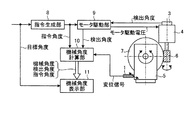
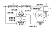
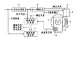
図1は、本発明の実施の形態1にかかる機械角度測定装置の概略構成を示すブロック図である。機械角度測定装置は、機械要素を回転させるモータの検出角度をフィードバックして、検出角度が指令角度に追従するようにモータを駆動することで、機械要素の機械角度を制御する装置において機械角度を測定する。まず、機械角度測定装置の一般的な構成例を、図1を使って説明する。サーボモータ4の回転運動は、例えばウォーム6とウォームホイール7とからなる減速機構により、ウォームホイール7と機械的に結合された主軸頭5に伝達される。ここでは、主軸頭5が、回転する機械要素となる。
FIG. 1 is a block diagram showing a schematic configuration of the mechanical angle measuring apparatus according to the first embodiment of the present invention. The machine angle measuring device feeds back the detected angle of the motor that rotates the machine element, and drives the motor so that the detected angle follows the command angle, thereby controlling the machine angle in the device that controls the machine angle of the machine element. taking measurement. First, a general configuration example of the mechanical angle measuring device will be described with reference to FIG. The rotational motion of the
モータ4の回転角度は角度検出器3により常時測定されており、モータ駆動部9では、指令生成部8から伝達される指令角度と、角度検出器3で測定された検出角度とが一致するようにモータ駆動電圧を逐次変更することで、モータ4の回転角度を制御する。指令生成部8では、上位装置から伝達またはオペレータにより入力された目標角度から指令角度が生成される。
The rotation angle of the
主軸頭5の回転角度(機械角度)は、理想的には検出角度と一致することが好ましい。しかし、実際には、減速機構の角度伝達誤差や重力による変形といった様々な要因により、機械角度が検出角度と一致することはほとんどない。すなわち、たとえ検出角度と指令角度が一致したとしても、本来制御したいはずの機械角度は指令角度とは一致していないことが多い。
The rotation angle (mechanical angle) of the
このため、指令生成部8およびモータ駆動部9には各種補正機能が備わっており、機械角度を指令角度となるべく一致するように制御している。この各種補正機能を有効に動作させるためには、機械角度の測定結果に基づいて補正機能のパラメータを適切に設定しておく必要がある。
For this reason, the
続いて、本発明の実施の形態にかかる機械角度測定装置について、図1を用いて説明する。本実施の形態1では、回転する機械要素上で回転に伴い変位が生じる箇所の変位を変位センサ1により測定し、機械角度計算部10では、角度検出器3により測定される検出角度と、変位センサ1により測定される変位(変位信号として出力)とから、変位センサ1の設置位置を推定し、変位センサ1の設置位置の推定結果に基づいて変位から機械角度を計算することを特徴とする。また、計算された機械角度が、機械角度表示部11に表示されることを特徴とする。
Subsequently, a mechanical angle measuring apparatus according to an embodiment of the present invention will be described with reference to FIG. In the first embodiment, the
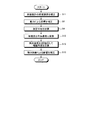
図2は、変位センサ1により機械角度を測定する手順を説明するためのフローチャートである。変位センサオフセット量計算ステップS1では、変位センサ1の設置位置のオフセットを計算する。
FIG. 2 is a flowchart for explaining a procedure for measuring the mechanical angle by the
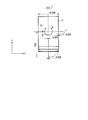
図3は、変位センサ1の設置位置のZ方向オフセット量について説明する図である。主軸頭5は円筒形であり、円筒の中心軸に直交する方向の軸まわりに回転するものとし、その回転軸をB軸とする。主軸頭の回転軸の方向をY軸、B軸の回転角度が0°の状態での円筒の中心軸をX軸とし、X軸とY軸に直交する軸をZ軸とする。図3は、B軸の回転角度が0°の状態での主軸頭5を、Y軸方向から見た図である。このとき、たとえば回転中心を通りX軸に平行な直線上の点を測定対象点とし、図3の1’の位置に変位センサを配置して、主軸頭5の回転により生じる測定対象点のZ方向の変位を測定することができれば、その変位から機械角度を求めることができる。特に、変位が微小である場合は、測定変位と機械角度は比例関係となる。すなわち、回転中心と測定対象点との間の距離と機械角度の積が測定変位となるので、測定変位を回転中心と測定対象点の間の距離で除することにより、機械角度を求めることができる。
FIG. 3 is a diagram for explaining the Z-direction offset amount of the installation position of the
しかしながら、回転中心を通る直線上の変位を測定することは一般には困難である場合が多い。前述の例では、図3の1’のように、主軸頭5の下端付近に変位センサを取り付けることになるが、この部分には工具などがすでに取り付けられている場合が多く、その場合には変位センサを取り付けられない。また、主軸頭5の長さの関係で回転中心と測定対象点の間の距離が長くなるため、変位センサの有効測定範囲が限られている場合には、角度の測定範囲が狭くなってしまう。
However, it is often difficult to measure a displacement on a straight line passing through the center of rotation. In the example described above, a displacement sensor is attached near the lower end of the
そこで、実際には変位センサを配置しやすく、かつ回転中心に近い点を測定対象点とすることになる。例えば、図3の1に示す主軸頭5の側面に変位センサを配置する。その場合には、変位センサで測定される変位と実際の機械角度の間の関係は、比例関係とはならなくなり、回転中心を通る直線からZ方向に離れた位置にセンサを配置することによる測定誤差が生じる。また、測定対象点の回転中心に対する相対位置を正確に把握するのは一般に難しい。そこで、回転中心からZ方向・X方向にオフセットした位置を測定対象点とし、主軸頭5の回転により生じる測定対象点のZ方向の変位から機械角度を求める場合の、測定誤差について解析し、さらにZ方向のオフセットとX方向のオフセットは未知の場合でも、変位センサで測定した位置と検出角度とからこれらのオフセットを推定する方法について考察する。なお、ここでは、B軸の回転角度は±1°以下の微小な角度とする。
Therefore, in practice, a point that is easy to place the displacement sensor and is close to the center of rotation is set as a measurement target point. For example, a displacement sensor is arranged on the side surface of the
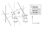
図4は、変位センサ1のZ方向オフセットによる測定誤差の発生原理を説明するための図である。図4において、測定半径(B軸回転中心位置からの−X方向オフセット)をrx[mm]、Z方向オフセットをrz[mm]、測定誤差をΔz[mm]、B軸の回転角度をθ[deg]とする。もし測定対象点がB軸回転中心をとおりX軸に平行な直線上にあれば、すなわちZ方向オフセットが0であれば、測定される変位は測定半径と回転角度の積rx・θとなる。しかしZ方向オフセットが0でない場合には、測定対象点における変位は、前述の測定半径と回転角度の積rx・θに、測定誤差Δzが加算された値となる。図4から、Z方向オフセットと測定誤差の和に回転角度の余弦を乗じたものがZ方向オフセットの値と等しくなることがわかる。これらを式で表すと、式(1)および式(2)となる。さらに、式(1)と式(2)を測定誤差Δzについて解くことで、式(3)を得る。
z=rz+Δz (1)
rz=zcosθ (2)
FIG. 4 is a diagram for explaining the generation principle of the measurement error due to the Z-direction offset of the
z = r z + Δz (1)
r z = z cos θ (2)

式(3)より、Z方向オフセットによる測定誤差ΔzはZ方向オフセットrzとB軸の回転角度θとから計算でき、B軸の回転角度が0度では測定誤差も0である。また、B軸回転角度の符号によらず、測定誤差は同じ値になることがわかる。 From equation (3), the measurement error Δz due to the Z-direction offset can be calculated from the Z-direction offset r z and the B-axis rotation angle θ, and the measurement error is zero when the B-axis rotation angle is 0 degrees. It can also be seen that the measurement error has the same value regardless of the sign of the B-axis rotation angle.
本実施の形態1の機械角度計算部10では、検出角度も同期して取得するため、便宜上検出角度をB軸の回転角度θ とすることで、変位センサ1のZ方向オフセットによる測定誤差を計算できる。そのために、まずステップS1では、回転中心線からみた変位センサ1の設置位置のZ方向オフセット量を計算する。
In the mechanical
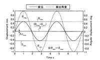
図5は、主軸頭5の側面の変位を測定するように変位センサ1を設置し、角度振幅が1deg、速度振幅が100deg/minの正弦波往復運動を行ったときの検出角度と変位の測定結果を示す図である。図5において、検出角度[deg]を破線で表し、変位センサによる測定結果[mm]を実線で表している。式(3)によると、回転角度θが最大となるときに測定誤差も最大となる。よって、検出角度の最大値をθmax[deg]、変位センサ1のZ方向オフセットによる測定誤差の最大値をΔzmax[mm]とすると、その関係は式(4)のように書ける。
FIG. 5 shows the detection angle and displacement measurement when the
ここで、変位の測定結果の最大値をDmax[mm]、最小値をDmin[mm]とすると、回転角度の符号によらず測定誤差は正の値となるので、測定誤差の最大値Δzmax[mm]は、式(3)から以下のように計算できる。 Here, if the maximum value of the displacement measurement result is D max [mm] and the minimum value is D min [mm], the measurement error is a positive value regardless of the sign of the rotation angle. Δz max [mm] can be calculated from Equation (3) as follows.
すなわち、式(5)により求めた測定誤差の最大値Δzmaxと、検出角度の最大値θmaxとから、式(4)により変位計のZ方向オフセット量rzを計算できる。図5に示した測定結果から変位センサ1のZ方向オフセット量を計算したところ、117.4mmとなった。このように、変位センサの正確な取り付け位置が未知の場合でも、正弦波指令角度を与えた場合における検出角度と変位の測定結果とから、変位センサ1のZ方向オフセット量を計算できる。
That is, the Z-direction offset amount r z of the displacement meter can be calculated by the equation (4) from the maximum value Δz max of the measurement error obtained by the equation (5) and the maximum value θ max of the detection angle. When the amount of offset in the Z direction of the
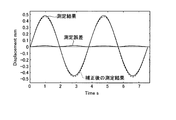
オフセット依存誤差計算ステップS2では、ステップS1で計算されたZ方向オフセット量を使って、式(3)によりZ方向オフセットによる測定誤差を計算する。さらに、オフセット依存誤差補正ステップS3において、ステップS2で計算された測定誤差を変位センサ1による測定結果から差し引くことで、変位センサ1のZ方向オフセットによる測定誤差を補正する。図6は、変位センサ1による測定結果とそのときの測定誤差、および測定誤差を補正したあとの結果を示す図である。
In the offset-dependent error calculation step S2, the measurement error due to the Z-direction offset is calculated by Equation (3) using the Z-direction offset amount calculated in Step S1. Further, in the offset dependent error correction step S3, the measurement error due to the Z-direction offset of the
測定半径計算ステップS4では、測定半径すなわちB軸回転中心からの−X方向オフセットを計算する。測定半径rxは変位測定結果の振幅とフィードバック角度の振幅との比として、式(6)により求められる。 In the measurement radius calculation step S4, the measurement radius, that is, the −X direction offset from the B-axis rotation center is calculated. The measurement radius r x is obtained by Equation (6) as the ratio of the amplitude of the displacement measurement result and the amplitude of the feedback angle.
式(6)を用いて、図5に示した測定結果から測定半径rxを計算したところ、27.4mmとなった。このように、正弦波指令角度を与えた場合における検出角度と変位の測定結果とから、変位センサ1のZ方向オフセット量と測定半径の両方、すなわち回転中心位置に対する変位センサ1の設置位置を計算できる。そして、機械角度計算ステップS5では、ステップS4で計算された測定半径を使い、変位センサ1により測定された変位を機械角度に変換する。
Using equation (6), the measurement radius r x was calculated from the measurement results shown in FIG. 5 and found to be 27.4 mm. As described above, both the Z-direction offset amount and the measurement radius of the
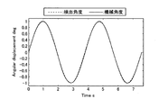
図7は、図2に示す手順により計算された機械角度と、そのときの検出角度を示す図である。図7からわかるように、検出角度と機械角度との間の誤差は運動の振幅と比べて大変微小であり、機械角度と検出角度とを重ねて表示したとしても読み取ることが難しい。そこで、何らかの方法により運動誤差を拡大表示する必要がある。 FIG. 7 is a diagram showing the machine angle calculated by the procedure shown in FIG. 2 and the detected angle at that time. As can be seen from FIG. 7, the error between the detected angle and the mechanical angle is very small compared to the amplitude of the movement, and it is difficult to read even if the mechanical angle and the detected angle are displayed in an overlapping manner. Therefore, it is necessary to enlarge and display the motion error by some method.
運動誤差を拡大表示するための方法の1つとして、円弧表示する方法がある。この方法は2つ以上の直進軸を有する機械の運動精度を評価するための方法として一般的な方法であり、円弧表示することの利点として誤差の拡大表示が容易な点がある。これは、実際の軌跡の平均半径(基準円半径)を求めてその平均半径と実際の軌跡との誤差を計算することで、平均値からの変動分のみを大きく拡大して表示できるためである。 One method for enlarging and displaying the motion error is to display an arc. This method is a general method as a method for evaluating the motion accuracy of a machine having two or more straight axes, and has an advantage that an enlarged display of errors is easy as an advantage of arc display. This is because the average radius of the actual trajectory (reference circle radius) is obtained, and the error between the average radius and the actual trajectory is calculated, so that only the variation from the average value can be enlarged and displayed. .
回転軸1軸の測定結果についても、同様の方法を適用することができる。すなわち、正弦波角度指令を与えた場合における検出角度と機械角度とを記録して第1のデータ組とし、検出角度と振幅が同じで位相が90度異なる描画用検出角度を演算により求め、機械角度と振幅が同じで位相が90度異なる描画用機械角度を演算により求め、描画用検出角度と描画用機械角度とを第2のデータ組とし、第1のデータ組と第2のデータ組を2次元平面上の直交する軸の検出移動量および機械移動量として円弧表示することができる。第1のデータ組と第2のデータ組は、機械角度計算部10によって出力される。すなわち、機械角度計算部10は、出力部としても機能する。なお、出力部を機械角度計算部10と別個に設けても構わない。
The same method can be applied to the measurement result of one rotation axis. That is, the detection angle and the machine angle when a sine wave angle command is given are recorded as a first data set, and the detection angle for drawing with the same detection angle and amplitude but 90 degrees in phase is obtained by calculation. A drawing machine angle having the same angle and amplitude and a phase of 90 degrees is obtained by calculation, the drawing detection angle and the drawing machine angle are set as the second data set, and the first data set and the second data set are A circular arc can be displayed as the detected movement amount and the mechanical movement amount of the orthogonal axes on the two-dimensional plane. The first data set and the second data set are output by the mechanical
なお、正弦波角度指令は余弦波角度指令としてもよい。また、描画用検出角度および描画用機械角度は、それぞれ検出角度および機械角度を直接用いるのではなく、演算により生成されるものである。例えば、それぞれ検出角度および機械角度の振幅と位相と周期を検出し、その振幅と位相と周期に基づいて正弦波関数のパラメータを決定して直交検出角度と機械検出角度とを計算したものでもよいし、指令角度と回転軸を駆動するサーボ系の特性を模擬した数式とから検出角度と機械角度とを推定し、その推定結果の位相を90度変化させたものとしてもよい。 The sine wave angle command may be a cosine wave angle command. In addition, the drawing detection angle and the drawing mechanical angle are generated not by directly using the detection angle and the mechanical angle, but by calculation. For example, the quadrature detection angle and the mechanical detection angle may be calculated by detecting the amplitude, phase, and period of the detection angle and the mechanical angle, respectively, determining parameters of the sine wave function based on the amplitude, phase, and period. Then, the detected angle and the mechanical angle may be estimated from the command angle and the mathematical formula simulating the characteristics of the servo system that drives the rotating shaft, and the phase of the estimation result may be changed by 90 degrees.
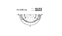
図8−1は、検出角度と機械角度とを円弧表示するために主軸頭5に行わせた運動を示す図である。図8−2〜8−4は、測定された検出角度と機械角度とを円弧表示した結果の例を示す図である。図8−1に示すように、B軸周りに回転する主軸頭5を±θ 度の範囲で正弦波往復運動させる。なお、検出角度と機械角度の円弧表示は、機械角度表示部11に表示される。したがって、機械角度をユーザに視覚的に認識させることができる。
FIG. 8A is a diagram illustrating a movement performed by the
図8−2は、そのときの測定結果を円弧一周分として表示した結果であり、角度誤差を半径方向に拡大して表示している。左右方向に現れている軌跡誤差が、運動方向反転時に生じた誤差である。図8−3は往復運動の往路と復路を180度分ずつに分割して表示した結果であり、図8−4は往路と復路の測定結果を重ねて表示した結果である。 FIG. 8-2 is a result of displaying the measurement result at that time as one round of the arc, and the angle error is enlarged and displayed in the radial direction. The trajectory error that appears in the left-right direction is an error that occurs when the motion direction is reversed. FIG. 8-3 is a result of displaying the forward and backward paths of the reciprocating motion divided by 180 degrees, and FIG. 8-4 is a result of displaying the measurement results of the forward and backward paths in an overlapping manner.
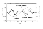
運動誤差を拡大表示するための他の方法として、基準角度を定義してその基準角度に対する誤差を表示する方法がある。すなわち、検出角度、機械角度、または指令角度から基準角度を求め、基準角度と検出角度および機械角度との誤差を計算し、基準角度と誤差との関係、または経過時間と誤差との関係を表示する。基準角度としては、例えば振幅と位相を検出角度または機械角度と一致させた正弦波とする方法や、サーボ系の特性を模擬した数学モデルにより指令角度に対する検出角度を計算しておく方法がある。 As another method for enlarging and displaying the motion error, there is a method of defining a reference angle and displaying an error with respect to the reference angle. In other words, the reference angle is obtained from the detected angle, machine angle, or command angle, the error between the reference angle and the detected angle and the machine angle is calculated, and the relationship between the reference angle and the error or the relationship between the elapsed time and the error is displayed. To do. Examples of the reference angle include a method of using a sine wave in which the amplitude and phase coincide with the detection angle or the mechanical angle, and a method of calculating the detection angle with respect to the command angle using a mathematical model that simulates the characteristics of the servo system.
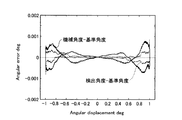
図9は、横軸を時間、縦軸を回転角度および角度誤差とした場合の測定結果を示す図である。図10は、横軸を回転角度、縦軸を角度誤差とした場合の測定結果を示す図である。図9および図10をみると、運動方向が反転する箇所では検出角度と機械角度の両方で角度誤差が大きく変化していることがわかる。さらに、検出角度よりも機械角度のほうが、角度誤差が大きいこともわかる。なお、図9や図10に示すような測定結果も機械角度計算部10によって出力されて、機械角度表示部11に表示される。これにより、機械角度をユーザに視覚的に認識させることができる。
FIG. 9 is a diagram showing measurement results when the horizontal axis represents time and the vertical axis represents the rotation angle and angle error. FIG. 10 is a diagram showing measurement results when the horizontal axis is the rotation angle and the vertical axis is the angle error. 9 and 10, it can be seen that the angle error greatly changes in both the detection angle and the machine angle at the place where the movement direction is reversed. Furthermore, it can be seen that the angle error is larger at the mechanical angle than at the detected angle. Note that the measurement results as shown in FIG. 9 and FIG. 10 are also output by the machine
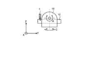
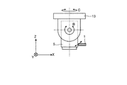
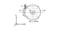
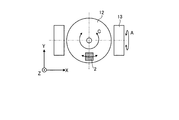
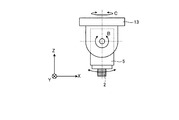
図11−1は、変位センサ1を使ってワークテーブルの回転角度と傾斜角度を測定する例を示す模式図である。図11−2は、図11−1に示す模式図を他の方向から見た図である。図12−1は、変位センサ1を使って主軸頭5の回転角度と傾斜角度を測定する他の例を示す模式図である。図12−2は、図12−1に示す模式図を他の方向から見た図である。A軸やC軸などの回転軸は傾斜軸支持部13に支持される。ワークテーブル12上には、変位測定用基準ブロックが設けられる。
FIG. 11A is a schematic diagram illustrating an example in which the rotation angle and the inclination angle of the work table are measured using the
ここまでは、主軸頭5がB軸周りに回転する場合を例に説明したが、例えば図11−1,11−2に示すように、ワークテーブル12がA軸とC軸周りに回転する場合についても、同様の方法で測定が可能である。また、図12−1,12−2に示すように、主軸頭5がC軸周りとB軸周りに回転する場合についても、同様の方法で測定が可能である。ほかの軸構成についても測定可能であることは、当業者であれば容易に想像できる。
Up to this point, the case where the
以上説明したように、変位センサ1で変位を測定して機械角度を算出するので、連続的な角度変化の測定が可能になる。また、正弦波指令角度を与えることで変位センサ1の設置位置を計算できるので、変位センサ1の設置位置を厳密に管理しなくてもよいため、メンテナンス性や使い勝手の向上を図ることができる。
As described above, since the mechanical angle is calculated by measuring the displacement with the
実施の形態2.
図13は、本発明の実施の形態2にかかる機械角度測定装置の概略構成を示すブロック図である。なお、上記実施の形態と同様の構成については、同様の符号を付して詳細な説明を省略する。本実施の形態2では、加速度センサ2の感度方向が、回転する機械要素の回転の接線方向を向くように加速度センサ2を設置する。また、機械角度計算部10が、加速度センサ2により測定される接線方向加速度および接線方向加速度を積分して得られる情報と、検出角度および検出角度を微分して得られる情報とを比較することで、加速度の測定誤差と加速度を積分することによる積分誤差とを補正して、機械角度を計算することを特徴とする。
FIG. 13: is a block diagram which shows schematic structure of the mechanical angle measuring
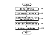
図14は、加速度センサ2により機械角度を測定する手順を説明するためのフローチャートである。加速度を測定する場合には、加速度センサ2の感度方向の向きによっては重力加速度gによる影響を受ける。そこで、まず重力成分補正ステップS6において重力による影響を補正する。例えば、図13に示すように主軸端に加速度センサ2を取付けて主軸頭5が回転する場合、その回転角度θ と加速度センサ2の感度方向に対する重力加速度成分は、式(7)のように表される。ここで、γはB軸回転中心線のZ軸周りの回転角度であり、本実施の形態2で測定対象とした回転軸では30度である。
GT=g・cos(γ)・sin(θ) (7)
FIG. 14 is a flowchart for explaining a procedure for measuring the mechanical angle by the
G T = g · cos (γ) · sin (θ) (7)
図15−1は、加速度センサ2を使ってワークテーブルの回転角度と傾斜角度を測定する例を示す模式図である。図15−2は、図15−1に示す模式図を他の方向から見た図である。図16−1は、加速度センサ2を使って主軸頭5の回転角度と傾斜角度を測定する他の例を示す模式図である。図16−2は、図16−1に示す模式図を他の方向から見た図である。
FIG. 15A is a schematic diagram illustrating an example in which the rotation angle and the inclination angle of the work table are measured using the
図13に示す回転軸では重力加速度gとその回転の接線方向成分GTとの関係は式(7)のようになるが、例えば図15−1,15−2に示すようにワークテーブル12がA軸とC軸周りに回転する場合や、図16−1,16−2に示すように、主軸頭5がC軸周りとB軸周りに回転する場合についての関係式についても、当業者であれば容易に導出することができる。また、ほかの軸構成についても同様に導出可能であることも、当業者であれば容易に想像できる。
Although the relationship of the rotation axis and the gravitational acceleration g and tangential component G T of rotation as shown in FIG. 13 is as Equation (7), for example, a work table 12, as shown in FIG. 15-1 and 15-2 Those skilled in the art also have relational expressions for the case of rotating around the A axis and the C axis, and the case where the
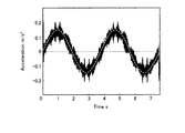
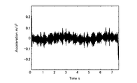
図17は、角度振幅を1deg、速度振幅を100deg/minとした場合における加速度の測定結果と、そのときの重力加速度による影響の推定値を示す図である。図18は、加速度の測定結果から重力加速度成分を差し引いて補正した結果を示す図である。重力加速度による影響は、検出角度をθ として式7により計算した。本実施の形態2における機械角度測定方法の重力成分補正ステップS6では、検出角度と重力加速度とから、重力加速度が接線方向加速度に及ぼす影響を推定し、接線方向加速度から差し引くことを特徴とする。
FIG. 17 is a diagram showing an acceleration measurement result when the angular amplitude is 1 deg and the velocity amplitude is 100 deg / min, and an estimated value of the influence due to gravitational acceleration at that time. FIG. 18 is a diagram illustrating a result of correction by subtracting the gravitational acceleration component from the acceleration measurement result. The influence of gravitational acceleration was calculated according to
速度計算ステップS7では加速度を積分することで速度を計算する。感度誤差および測定半径補正ステップS8では、加速度を積分して得た速度と検出角度を微分して得た角速度の振幅を比較し、加速度を積分して得た速度の振幅が検出位置を微分して得た角速度の振幅と一致するように、加速度を積分して得た速度を係数倍して角速度に変換する。これは、加速度センサの感度誤差と測定半径を同時に補正したことに相当する。 In the speed calculation step S7, the speed is calculated by integrating the acceleration. In the sensitivity error and measurement radius correction step S8, the velocity obtained by integrating the acceleration and the amplitude of the angular velocity obtained by differentiating the detected angle are compared, and the velocity amplitude obtained by integrating the acceleration differentiates the detected position. The velocity obtained by integrating the acceleration is multiplied by a coefficient so as to coincide with the amplitude of the angular velocity obtained in this way, and converted into an angular velocity. This corresponds to correcting the sensitivity error of the acceleration sensor and the measurement radius at the same time.
機械角度計算ステップS9では、ステップS8で計算された角速度を積分して機械角度を計算する。さらに、積分誤差補正ステップS10において、機械加速度を計算する際の積分誤差による影響を補正する。 In the mechanical angle calculation step S9, the angular velocity calculated in step S8 is integrated to calculate the mechanical angle. Further, in the integration error correction step S10, the influence due to the integration error when calculating the mechanical acceleration is corrected.
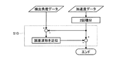
図19は、図14に示すステップS10における処理を詳細に説明するための図である。ステップS10では、加速度を2回積分して得た機械角度と検出角度との差を計算し、事前に準備した想定される積分誤差の近似式をつかって機械角度と検出角度との差を近似する。この近似式により得られる積分誤差の推定値を機械角度から差し引くことで、積分誤差による影響を補正する。 FIG. 19 is a diagram for explaining the processing in step S10 shown in FIG. 14 in detail. In step S10, the difference between the mechanical angle obtained by integrating the acceleration twice and the detected angle is calculated, and the difference between the mechanical angle and the detected angle is approximated using an approximate expression of an assumed integral error prepared in advance. To do. By subtracting the estimated value of the integral error obtained from this approximate expression from the mechanical angle, the influence of the integral error is corrected.
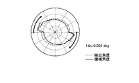
図20は、実施の形態2により測定された検出角度と機械角度とを円弧表示した結果の例を示す図である。図20は、角度振幅を1deg、速度振幅を200deg/minとした場合の結果であり、1/4周期ずらした結果を使って円弧軌跡として表示している。 FIG. 20 is a diagram illustrating an example of a result of displaying the detected angle and the mechanical angle measured according to the second embodiment in an arc. FIG. 20 shows the results when the angular amplitude is 1 deg and the velocity amplitude is 200 deg / min, and is displayed as a circular arc locus using the result shifted by ¼ period.
また、検出角度を破線で表し、機械角度を実線で表している。各象限切り替え部、すなわち運動方向が反転する箇所では、検出角度と機械角度の両方に段差状の誤差が発生していること、および検出角度と機械角度とでは誤差の波形に違いがあることがわかる。このような円弧表示は、機械角度計算部10によって出力されて、機械角度表示部11に表示される。これにより、機械角度をユーザに視覚的に認識させることができる。
Further, the detection angle is represented by a broken line, and the mechanical angle is represented by a solid line. At each quadrant switching part, that is, where the movement direction is reversed, there is a stepped error in both the detection angle and the machine angle, and there is a difference in the error waveform between the detection angle and the machine angle. Recognize. Such an arc display is output by the machine
なお、以上の実施の形態では、主軸頭がB軸周りに回転する場合を例に説明したが、例えば図15−1,15−2に示すようにワークテーブル12がA軸とC軸周りに回転する場合についても、同様の方法で測定が可能である。また、図16−1,16−2に示すように主軸頭5がC軸周りとB軸周りに回転する場合についても、同様の方法で測定が可能である。ほかの軸構成についても測定可能であることは、当業者であれば容易に想像できる。
In the above embodiment, the case where the spindle head rotates around the B axis has been described as an example. However, for example, as shown in FIGS. 15A and 15B, the work table 12 is rotated around the A axis and the C axis. Even in the case of rotation, measurement can be performed by the same method. Also, as shown in FIGS. 16-1 and 16-2, the same method can be used when the
以上説明したように、加速度センサ2で加速度を測定して機械角度を算出するので、連続的な角度変化の測定が可能になる。また、重力加速度が加速度に及ぼす影響を推定し、その影響を加速度から差し引くので、重力の影響を受ける場合でも機械角度を測定できる。
As described above, since the mechanical angle is calculated by measuring the acceleration with the
実施の形態3.
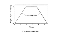
本発明の実施の形態3として、加速度センサ2を使って連続的な回転運動中の回転角度を測定する方法を例にあげて説明する。なお、上記実施の形態と同様の構成については、同様の符号を付して詳細な説明を省略する。図21−1は、B軸周りに回転動作する主軸頭5を示す図である。加速度センサ2はその感度方向が回転運動の接線方向を向くように設置される。図21−2は、図21−1に示す回転動作における時間と回転角度の関係を示す図である。図21−2に示すように、主軸頭5を0度と90度との間で等速回転させたときの回転角度を測定する。
As a third embodiment of the present invention, a method of measuring a rotation angle during continuous rotational movement using the
なお、本実施の形態3では、主軸頭5がB軸周りに回転する場合を例にあげて説明しているが、例えば図15−1,15−2に示すようにワークテーブル12がA軸とC軸周りに回転する場合についても、同様の方法で測定が可能である。また、図16−1,16−2に示すように主軸頭5がC軸周りとB軸周りに回転する場合についても、同様の方法で測定が可能である。なお、他の軸構成についても測定可能であることは、当業者であれば容易に想像できる。また、測定する回転角度の範囲についても、測定対象とする回転軸の可動範囲に応じて任意に設定可能である。
In the third embodiment, the case where the
図22は、加速度センサ2を使って等速回転中の回転角度を測定するための手順を説明するためのフローチャートである。まず、感度誤差補正ステップS11では、加速度センサの設置誤差や感度誤差等に起因する測定誤差を補正する。
FIG. 22 is a flowchart for explaining a procedure for measuring a rotation angle during constant speed rotation using the
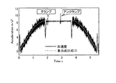
図23は、図21−1,21−2に示す運動を行った場合における加速度の測定結果と、そのときの重力成分の推定結果を示す図である。重力成分の推定結果は式(7)によって求められるものである。図23によると、停止中の加速度の測定結果(2〜3秒付近)は重力加速度の推定値とわずかにずれており、これは、加速度センサ2の感度誤差や設置誤差による影響である。また、停止中の加速度波形にはスパイク状の加速度変化が観察されるが、これは測定対象とした回転軸が有するクランプ機構の影響によるものである。
FIG. 23 is a diagram showing an acceleration measurement result when the motions shown in FIGS. 21-1 and 21-2 are performed, and an estimation result of the gravity component at that time. The estimation result of the gravitational component is obtained by Expression (7). According to FIG. 23, the measurement result of acceleration while stopped (around 2 to 3 seconds) slightly deviates from the estimated value of gravitational acceleration, which is due to the sensitivity error and the installation error of the
感度誤差補正ステップS11では、検出角度からモータの停止を検知するとともに重力加速度による影響を推定し、その推定結果と加速度の測定結果とが一致するように加速度センサ2の測定結果を補正する。その際、クランプ機構が動作して加速度の測定結果に影響を及ぼす箇所のデータは除いておくことを特徴とする。図24は、図22に示すステップS11における加速度センサ2による測定結果を補正した場合の加速度の測定結果と重力成分の推定値とを示す図である。
In the sensitivity error correction step S11, the stop of the motor is detected from the detected angle, the influence of the gravitational acceleration is estimated, and the measurement result of the
つぎに、重力成分補正ステップS6では、感度誤差補正ステップS11で補正された加速度データから重力成分の推定値を差し引くことで、重力加速度による影響を補正する。図25は、図22に示すステップS6において重力成分を補正したあとの加速度の測定結果を示す図である。この結果が、回転運動に伴う接線方向加速度となる。 Next, in the gravity component correction step S6, the influence due to the gravity acceleration is corrected by subtracting the estimated value of the gravity component from the acceleration data corrected in the sensitivity error correction step S11. FIG. 25 is a diagram showing a measurement result of acceleration after correcting the gravity component in step S6 shown in FIG. This result is the tangential acceleration associated with the rotational motion.
つぎに、検出角度を2回微分して得た検出角加速度とステップS6により補正された接線方向加速度とを比較して加速度の測定半径を計算し(ステップS4)、角加速度計算ステップS12で接線方向加速度を角加速度に変換する。具体的には、加速および減速中であることを検知し、検出角加速度の最大値と加速度センサ2により測定された接線方向加速度の最大値との比を測定半径として計算し、接線方向加速度を測定半径で除することで、機械角加速度を計算する。
Next, the detected angular acceleration obtained by differentiating the detected angle twice and the tangential acceleration corrected in step S6 are compared to calculate the measurement radius of the acceleration (step S4), and the tangent is calculated in the angular acceleration calculating step S12. Convert directional acceleration into angular acceleration. Specifically, it is detected that the vehicle is accelerating and decelerating, and the ratio between the maximum value of the detected angular acceleration and the maximum value of the tangential acceleration measured by the
本実施の形態3において計算された測定半径は、277.2mmであった。図26は、図22に示すステップS12により計算された機械角加速度と、検出角度を2回微分して得た検出角加速度とを示す図である。図26によると、機械角加速度のほうが振動の振幅が大きくなっており、これは回転軸の駆動機構に存在する誤差や機械的な振動による影響である。 The measurement radius calculated in the third embodiment was 277.2 mm. FIG. 26 is a diagram showing the mechanical angular acceleration calculated in step S12 shown in FIG. 22 and the detected angular acceleration obtained by differentiating the detected angle twice. According to FIG. 26, the mechanical angular acceleration has a larger vibration amplitude, which is an influence of an error existing in the drive mechanism of the rotating shaft and mechanical vibration.
機械角度計算ステップS13では、ステップS12により計算された機械角加速度を2回積分して機械角度を計算する。さらに、ステップS10では、積分誤差による影響を同定して機械角度の測定結果に含まれる積分誤差による影響を補正する。積分誤差の補正方法としては、図19に示すように、加速度を2回積分して得た機械角度と検出角度との差を計算し、事前に準備した想定される積分誤差の近似式をつかって機械角度と検出角度との差を近似するとともに、この近似式により得られる積分誤差の推定値を機械角度から差し引く方法が適用できる。 In the machine angle calculation step S13, the machine angle is calculated by integrating the machine angular acceleration calculated in step S12 twice. Further, in step S10, the influence due to the integration error is identified, and the influence due to the integration error included in the measurement result of the mechanical angle is corrected. As shown in FIG. 19, the integration error correction method calculates the difference between the mechanical angle obtained by integrating the acceleration twice and the detected angle, and uses an approximation formula of an assumed integration error prepared in advance. Thus, it is possible to apply a method of approximating the difference between the mechanical angle and the detected angle and subtracting the estimated value of the integral error obtained from this approximation from the mechanical angle.
図27は、実施の形態3により測定された等速回転中の回転角度を示す図である。図27は、検出角度と機械角度との誤差を計算し、横軸を検出角度、縦軸を誤差として表示した結果である。本実施の形態3の機械角度測定方法では検出角度と加速度センサ2による測定結果とを時間的に同期して測定しているため、加速度センサ2による測定結果を積分した結果である機械角度も検出角度と時間的に同期していることになる。すなわち、機械角度と検出角度との誤差は回転軸の駆動機構に存在する機械的な誤差を表している。
FIG. 27 is a diagram illustrating a rotation angle during constant speed rotation measured according to the third embodiment. FIG. 27 shows the result of calculating the error between the detected angle and the mechanical angle and displaying the detected angle on the horizontal axis and the error on the vertical axis. In the mechanical angle measurement method according to the third embodiment, since the detection angle and the measurement result by the
図27では、0度から90度まで主軸頭5を回転させた場合の結果と、逆に90度から0度まで主軸頭5を回転させた場合の結果とを重ねて表示している。図27によると、どちらの回転方向においても15度周期の変動が現れている。測定対象とした回転軸の減速機構は減速比が1/24であり、減速機構の入力軸1回転あたりの機械角度が15度に相当することから、15度周期の変動は減速機構の影響によるものであるといえる。
In FIG. 27, the result of rotating the
なお、図27は、結果として検出角度と誤差との関係を表示したものであるが、これを機械角度と誤差との関係として表示してもよいし、時間と誤差との関係として表示してもよい。また、これらの関係を示す情報は、機械角度計算部10によって出力されて、機械角度表示部11に表示される。これにより、機械角度をユーザに視覚的に認識させることができる。
FIG. 27 shows the relationship between the detected angle and the error as a result, but this may be displayed as the relationship between the mechanical angle and the error, or as the relationship between the time and the error. Also good. Information indicating these relationships is output by the machine
実施の形態4.
本発明の実施の形態4として、角速度センサを使って回転角度を測定する方法を例に挙げて説明する。なお、上記実施の形態と同様の構成については、同様の符号を付して詳細な説明を省略する。本実施の形態4では、回転する機械要素上の任意の位置に角速度センサ15の感度方向が回転軸の回転方向と一致するように設置され、機械角度計算部10では、角速度センサ15により測定される角速度および角速度を積分して得られる情報と、検出角度および検出角度を微分して得られる情報とを比較することで、角速度の測定誤差と角速度を積分することによる積分誤差とを補正して、機械角度を計算する。
As a fourth embodiment of the present invention, a method of measuring a rotation angle using an angular velocity sensor will be described as an example. In addition, about the structure similar to the said embodiment, the same code | symbol is attached | subjected and detailed description is abbreviate | omitted. In the fourth embodiment, the
図28は、本発明の実施の形態4にかかる機械角度測定装置の概略構成を示すブロック図である。角速度センサ15は、その回転の感度方向を測定対象の回転軸と一致するようにし、機械要素上に設置する。図29は、角速度センサ15を使う場合の機械角度計算部10の処理手順を示すフローチャートである。
FIG. 28 is a block diagram illustrating a schematic configuration of the mechanical angle measurement apparatus according to the fourth embodiment of the present invention. The
まず、機械角度計算ステップS9において、角速度を1回積分して角度とする。さらに、積分誤差補正ステップS10において、角速度を積分した際に生じる積分誤差による影響を補正する。積分誤差の補正アルゴリズムは、加速度センサ2による場合と同じ方法(図19を参照)が適用できる。これにより、上記実施の形態2,3と同様の効果を得ることができ、運動方向反転時の挙動や等速回転中の回転むらといった現象を測定できる。
First, in the mechanical angle calculation step S9, the angular velocity is integrated once to obtain an angle. Further, in the integration error correction step S10, the influence due to the integration error generated when the angular velocity is integrated is corrected. As the integration error correction algorithm, the same method (see FIG. 19) as in the case of using the
なお、図11−1,11−2,12−1,12−2,15−1,15−2,16−1,16−2に示すような回転軸の構成に対しても、同様に角速度センサ15によって機械角度を測定できることは、当業者であれば容易に想像できる。
In addition, the angular velocity is similarly applied to the configuration of the rotating shaft as shown in FIGS. 11-1, 11-2, 12-1, 12-2, 15-1, 15-2, 16-1, 16-2. Those skilled in the art can easily imagine that the mechanical angle can be measured by the
以上説明したように、角速度センサ15で変位を測定して機械角度を算出するので、連続的な角度変化の測定が可能になる。
As described above, since the mechanical angle is calculated by measuring the displacement by the
以上のように、本発明にかかる機械角度測定装置は、回転軸を有する工作機械の機械角度を測定するのに有用である。 As described above, the machine angle measuring device according to the present invention is useful for measuring the machine angle of a machine tool having a rotating shaft.
1 変位センサ
2 加速度センサ
3 角度検出器
4 サーボモータ
5 主軸頭(機械要素)
6 ウォーム
7 ウォームホイール
8 指令生成部
9 モータ駆動部
10 機械角度計算部(出力部)
11 機械角度表示部
12 ワークテーブル
13 傾斜軸支持部
14 変位測定用基準ブロック
15 角速度センサ
DESCRIPTION OF
6
DESCRIPTION OF
Claims (9)
回転する前記機械要素の位置、加速度および角速度の少なくとも1つを測定するセンサと、
前記検出角度と前記センサによる測定結果とから前記機械角度を計算する機械角度計算部と、を備えることを特徴とする機械角度測定装置。 The machine angle is measured in a device that controls the machine angle of the machine element by feeding back the detected angle of the motor that rotates the machine element and driving the motor so that the detected angle follows the command angle. A mechanical angle measuring device,
A sensor for measuring at least one of the position, acceleration and angular velocity of the rotating mechanical element;
A machine angle measurement device comprising: a machine angle calculation unit that calculates the machine angle from the detected angle and a measurement result by the sensor.
前記変位センサは、前記機械要素上で回転に伴い変位が生じる箇所に設置され、
前記機械角度計算部は、前記検出角度と前記変位センサにより測定される変位とから前記変位センサの設置位置を推定し、前記変位センサの設置位置の推定結果に基づいて前記変位から前記機械角度を計算することを特徴とする請求項1に記載の機械角度測定装置。 The sensor is a displacement sensor;
The displacement sensor is installed at a location where displacement occurs with rotation on the machine element,
The mechanical angle calculation unit estimates an installation position of the displacement sensor from the detected angle and a displacement measured by the displacement sensor, and calculates the mechanical angle from the displacement based on an estimation result of the installation position of the displacement sensor. The mechanical angle measuring device according to claim 1, wherein the mechanical angle measuring device calculates the mechanical angle.
前記加速度センサは、その感度方向が、前記機械要素の回転の接線方向を向くように設置され、
前記機械角度計算部では、前記加速度センサにより測定される接線方向加速度および前記接線方向加速度を積分して得られる情報と、前記検出角度および前記検出角度を微分して得られる情報とを比較し、前記接線方向加速度の測定誤差と前記接線方向加速度を積分することによる積分誤差とを補正して、前記機械角度を計算することを特徴とする請求項1に記載の機械角度測定装置。 The sensor is an acceleration sensor;
The acceleration sensor is installed so that the direction of sensitivity faces the tangential direction of rotation of the mechanical element,
The mechanical angle calculation unit compares the information obtained by integrating the tangential acceleration measured by the acceleration sensor and the tangential acceleration with the information obtained by differentiating the detection angle and the detection angle, The mechanical angle measurement apparatus according to claim 1, wherein the mechanical angle is calculated by correcting a measurement error of the tangential acceleration and an integration error due to integration of the tangential acceleration.
前記角速度センサは、その感度方向が前記機械要素の回転軸の回転方向と一致するように前記機械要素上に設置され、
前記機械角度計算部は、前記角速度センサにより測定される角速度および前記角速度を積分して得られる情報と、前記検出角度および前記検出角度を微分して得られる情報とを比較することで、前記角速度の測定誤差と前記角速度を積分することによる積分誤差とを補正して、前記機械角度を計算することを特徴とする請求項1に記載の機械角度測定装置。 The sensor is an angular velocity sensor;
The angular velocity sensor is installed on the machine element such that the direction of sensitivity coincides with the rotation direction of the rotation axis of the machine element,
The mechanical angle calculation unit compares the angular velocity measured by the angular velocity sensor and the information obtained by integrating the angular velocity with the information obtained by differentiating the detected angle and the detected angle. The mechanical angle measuring apparatus according to claim 1, wherein the mechanical angle is calculated by correcting the measurement error and the integral error caused by integrating the angular velocity.
出力された前記第1のデータ組と前記第2のデータ組を2次元平面上の直交する軸の検出移動量および機械移動量として円弧表示する機械角度表示部と、をさらに備えることを特徴とする請求項1に記載の機械角度測定装置。 When the sine wave angle command is given, the detected angle and the mechanical angle are output as a first data set recorded, and the detected angle for drawing is the same as the detected angle and the phase is 90 degrees. An output unit that obtains a drawing machine angle having the same amplitude as the machine angle and a phase different by 90 degrees by calculation, and outputs the drawing detection angle and the drawing machine angle as a second data set;
A mechanical angle display unit for displaying the output first data set and the second data set as arcs as detected movement amounts and mechanical movement amounts of orthogonal axes on a two-dimensional plane; The mechanical angle measuring device according to claim 1.
出力された前記基準角度と前記誤差との関係、または経過時間と前記誤差との関係を表示する表示部と、をさらに備えることを特徴とする請求項1に記載の機械角度測定装置。 A reference angle is obtained from the detected angle, the mechanical angle, or the command angle, an error between the reference angle and the detected angle and the mechanical angle is calculated, and a relationship between the reference angle and the error, or an elapsed time, An output unit for outputting a relationship with the error;
The mechanical angle measurement apparatus according to claim 1, further comprising a display unit that displays a relationship between the output reference angle and the error, or a relationship between elapsed time and the error.
出力された前記検出角度、前記機械角度または時間と、前記誤差との関係を表示する表示部と、をさらに備えることを特徴とする請求項1に記載の機械角度測定装置。 An output unit that calculates an error between the detected angle and the mechanical angle, and outputs a relationship between the detected angle, the mechanical angle or time, and the error;
The mechanical angle measuring apparatus according to claim 1, further comprising a display unit that displays a relationship between the output detection angle, the mechanical angle or time, and the error.
Priority Applications (1)
| Application Number | Priority Date | Filing Date | Title |
|---|---|---|---|
| JP2010288618A JP5300831B2 (en) | 2010-12-24 | 2010-12-24 | Mechanical angle measuring device |
Applications Claiming Priority (1)
| Application Number | Priority Date | Filing Date | Title |
|---|---|---|---|
| JP2010288618A JP5300831B2 (en) | 2010-12-24 | 2010-12-24 | Mechanical angle measuring device |
Publications (2)
| Publication Number | Publication Date |
|---|---|
| JP2012137331A true JP2012137331A (en) | 2012-07-19 |
| JP5300831B2 JP5300831B2 (en) | 2013-09-25 |
Family
ID=46674874
Family Applications (1)
| Application Number | Title | Priority Date | Filing Date |
|---|---|---|---|
| JP2010288618A Active JP5300831B2 (en) | 2010-12-24 | 2010-12-24 | Mechanical angle measuring device |
Country Status (1)
| Country | Link |
|---|---|
| JP (1) | JP5300831B2 (en) |
Cited By (3)
| Publication number | Priority date | Publication date | Assignee | Title |
|---|---|---|---|---|
| JP2015191271A (en) * | 2014-03-27 | 2015-11-02 | 三菱電機株式会社 | trajectory error display device |
| JP2016522885A (en) * | 2013-04-19 | 2016-08-04 | ストウ・ウッドワード・ライセンスコ,リミテッド・ライアビリティ・カンパニー | Industrial roll with triggering system for sensors for operating parameters |
| CN119794884A (en) * | 2025-02-25 | 2025-04-11 | 中国工程物理研究院机械制造工艺研究所 | A method, system and medium for detecting spatial posture error of a moving part |
Citations (6)
| Publication number | Priority date | Publication date | Assignee | Title |
|---|---|---|---|---|
| JP3396464B2 (en) * | 2000-01-26 | 2003-04-14 | 三星電子株式会社 | Apparatus and method for measuring rotation angle of rotating body |
| JP2004205288A (en) * | 2002-12-24 | 2004-07-22 | Mori Seiki Co Ltd | Measuring device and accuracy analysis device having the same |
| JP2004336913A (en) * | 2003-05-08 | 2004-11-25 | Koyo Seiko Co Ltd | Motor controller |
| JP2007333712A (en) * | 2006-06-19 | 2007-12-27 | Tokyo Univ Of Agriculture & Technology | Inclination angle measuring device, machine tool equipped with the same, and inclination angle calibration method for machine tool |
| JP2008059362A (en) * | 2006-08-31 | 2008-03-13 | Toshiba Corp | Servo control device |
| JP4256353B2 (en) * | 2005-02-17 | 2009-04-22 | ファナック株式会社 | Servo control device and servo system adjustment method |
-
2010
- 2010-12-24 JP JP2010288618A patent/JP5300831B2/en active Active
Patent Citations (6)
| Publication number | Priority date | Publication date | Assignee | Title |
|---|---|---|---|---|
| JP3396464B2 (en) * | 2000-01-26 | 2003-04-14 | 三星電子株式会社 | Apparatus and method for measuring rotation angle of rotating body |
| JP2004205288A (en) * | 2002-12-24 | 2004-07-22 | Mori Seiki Co Ltd | Measuring device and accuracy analysis device having the same |
| JP2004336913A (en) * | 2003-05-08 | 2004-11-25 | Koyo Seiko Co Ltd | Motor controller |
| JP4256353B2 (en) * | 2005-02-17 | 2009-04-22 | ファナック株式会社 | Servo control device and servo system adjustment method |
| JP2007333712A (en) * | 2006-06-19 | 2007-12-27 | Tokyo Univ Of Agriculture & Technology | Inclination angle measuring device, machine tool equipped with the same, and inclination angle calibration method for machine tool |
| JP2008059362A (en) * | 2006-08-31 | 2008-03-13 | Toshiba Corp | Servo control device |
Cited By (3)
| Publication number | Priority date | Publication date | Assignee | Title |
|---|---|---|---|---|
| JP2016522885A (en) * | 2013-04-19 | 2016-08-04 | ストウ・ウッドワード・ライセンスコ,リミテッド・ライアビリティ・カンパニー | Industrial roll with triggering system for sensors for operating parameters |
| JP2015191271A (en) * | 2014-03-27 | 2015-11-02 | 三菱電機株式会社 | trajectory error display device |
| CN119794884A (en) * | 2025-02-25 | 2025-04-11 | 中国工程物理研究院机械制造工艺研究所 | A method, system and medium for detecting spatial posture error of a moving part |
Also Published As
| Publication number | Publication date |
|---|---|
| JP5300831B2 (en) | 2013-09-25 |
Similar Documents
| Publication | Publication Date | Title |
|---|---|---|
| US7779553B2 (en) | Oscillating scanning probe with constant contact force | |
| JP5111031B2 (en) | Displacement detection method and motor control device | |
| EP1898428B1 (en) | Surface-profile measuring instrument | |
| JP6149337B1 (en) | Surface shape measuring device | |
| US10564032B2 (en) | Vibration mode determining apparatus | |
| CN105723182A (en) | Reduction of errors of a rotating device used during the determination of co-ordinates of a workpiece or during the machining of a workpiece | |
| JP5288320B2 (en) | Apparatus and method for measuring rotational balance of high-speed rotating body | |
| EP2542853B1 (en) | Surface measurement instrument and calibration thereof | |
| JP2012196749A (en) | Robot device | |
| JP5388823B2 (en) | Trajectory measuring device | |
| JP5851436B2 (en) | Processing apparatus and processing method | |
| CN107210690A (en) | The angular error means for correcting of position detector and angular error bearing calibration | |
| JP5395835B2 (en) | Feedback device and feedback method for controlling servo motor | |
| JP6657552B2 (en) | Flatness measurement method | |
| JP5300831B2 (en) | Mechanical angle measuring device | |
| JP4992078B2 (en) | Inclination angle measuring device, machine tool equipped with the same, and inclination angle calibration method for machine tool | |
| JP6719684B1 (en) | Numerical control device | |
| JP2005037197A (en) | Contact surface shape measuring apparatus and measuring method | |
| JP2018128350A (en) | Position detecting device, stage device, and shape measuring device | |
| JP2006042537A (en) | Brushless dc motor added with magnetic encoder and signal processing circuit | |
| JP2023156642A (en) | Method for measuring acceleration sensor characteristics and device for measuring acceleration sensor characteristics | |
| KR101263745B1 (en) | Method for estimating angular position output error of rotary angular detection sensor equipped on electro-optical device | |
| JP6846673B2 (en) | Angle correction method and angle correction device for surface shape measuring device | |
| JP4292675B2 (en) | Machine Tools | |
| JP6984846B2 (en) | True azimuth measurement method |
Legal Events
| Date | Code | Title | Description |
|---|---|---|---|
| A621 | Written request for application examination |
Free format text: JAPANESE INTERMEDIATE CODE: A621 Effective date: 20120928 |
|
| TRDD | Decision of grant or rejection written | ||
| A01 | Written decision to grant a patent or to grant a registration (utility model) |
Free format text: JAPANESE INTERMEDIATE CODE: A01 Effective date: 20130521 |
|
| A61 | First payment of annual fees (during grant procedure) |
Free format text: JAPANESE INTERMEDIATE CODE: A61 Effective date: 20130618 |
|
| R150 | Certificate of patent or registration of utility model |
Ref document number: 5300831 Country of ref document: JP Free format text: JAPANESE INTERMEDIATE CODE: R150 Free format text: JAPANESE INTERMEDIATE CODE: R150 |
|
| R250 | Receipt of annual fees |
Free format text: JAPANESE INTERMEDIATE CODE: R250 |
|
| R250 | Receipt of annual fees |
Free format text: JAPANESE INTERMEDIATE CODE: R250 |
|
| R250 | Receipt of annual fees |
Free format text: JAPANESE INTERMEDIATE CODE: R250 |
|
| R250 | Receipt of annual fees |
Free format text: JAPANESE INTERMEDIATE CODE: R250 |
|
| R250 | Receipt of annual fees |
Free format text: JAPANESE INTERMEDIATE CODE: R250 |
|
| R250 | Receipt of annual fees |
Free format text: JAPANESE INTERMEDIATE CODE: R250 |
|
| R250 | Receipt of annual fees |
Free format text: JAPANESE INTERMEDIATE CODE: R250 |
|
| R250 | Receipt of annual fees |
Free format text: JAPANESE INTERMEDIATE CODE: R250 |
|
| R250 | Receipt of annual fees |
Free format text: JAPANESE INTERMEDIATE CODE: R250 |
|
| R250 | Receipt of annual fees |
Free format text: JAPANESE INTERMEDIATE CODE: R250 |