JP2012139500A - 形状適合プロステーシス供給システム及びその配置方法 - Google Patents
形状適合プロステーシス供給システム及びその配置方法 Download PDFInfo
- Publication number
- JP2012139500A JP2012139500A JP2011284584A JP2011284584A JP2012139500A JP 2012139500 A JP2012139500 A JP 2012139500A JP 2011284584 A JP2011284584 A JP 2011284584A JP 2011284584 A JP2011284584 A JP 2011284584A JP 2012139500 A JP2012139500 A JP 2012139500A
- Authority
- JP
- Japan
- Prior art keywords
- graft
- diameter
- stent
- perforation
- tangent
- Prior art date
- Legal status (The legal status is an assumption and is not a legal conclusion. Google has not performed a legal analysis and makes no representation as to the accuracy of the status listed.)
- Granted
Links
Images





Classifications
-
- A—HUMAN NECESSITIES
- A61—MEDICAL OR VETERINARY SCIENCE; HYGIENE
- A61F—FILTERS IMPLANTABLE INTO BLOOD VESSELS; PROSTHESES; DEVICES PROVIDING PATENCY TO, OR PREVENTING COLLAPSING OF, TUBULAR STRUCTURES OF THE BODY, e.g. STENTS; ORTHOPAEDIC, NURSING OR CONTRACEPTIVE DEVICES; FOMENTATION; TREATMENT OR PROTECTION OF EYES OR EARS; BANDAGES, DRESSINGS OR ABSORBENT PADS; FIRST-AID KITS
- A61F2/00—Filters implantable into blood vessels; Prostheses, i.e. artificial substitutes or replacements for parts of the body; Appliances for connecting them with the body; Devices providing patency to, or preventing collapsing of, tubular structures of the body, e.g. stents
- A61F2/95—Instruments specially adapted for placement or removal of stents or stent-grafts
- A61F2/962—Instruments specially adapted for placement or removal of stents or stent-grafts having an outer sleeve
- A61F2/966—Instruments specially adapted for placement or removal of stents or stent-grafts having an outer sleeve with relative longitudinal movement between outer sleeve and prosthesis, e.g. using a push rod
- A61F2/9661—Instruments specially adapted for placement or removal of stents or stent-grafts having an outer sleeve with relative longitudinal movement between outer sleeve and prosthesis, e.g. using a push rod the proximal portion of the stent or stent-graft is released first
-
- A—HUMAN NECESSITIES
- A61—MEDICAL OR VETERINARY SCIENCE; HYGIENE
- A61F—FILTERS IMPLANTABLE INTO BLOOD VESSELS; PROSTHESES; DEVICES PROVIDING PATENCY TO, OR PREVENTING COLLAPSING OF, TUBULAR STRUCTURES OF THE BODY, e.g. STENTS; ORTHOPAEDIC, NURSING OR CONTRACEPTIVE DEVICES; FOMENTATION; TREATMENT OR PROTECTION OF EYES OR EARS; BANDAGES, DRESSINGS OR ABSORBENT PADS; FIRST-AID KITS
- A61F2/00—Filters implantable into blood vessels; Prostheses, i.e. artificial substitutes or replacements for parts of the body; Appliances for connecting them with the body; Devices providing patency to, or preventing collapsing of, tubular structures of the body, e.g. stents
- A61F2/02—Prostheses implantable into the body
- A61F2/04—Hollow or tubular parts of organs, e.g. bladders, tracheae, bronchi or bile ducts
- A61F2/06—Blood vessels
- A61F2/07—Stent-grafts
-
- A—HUMAN NECESSITIES
- A61—MEDICAL OR VETERINARY SCIENCE; HYGIENE
- A61F—FILTERS IMPLANTABLE INTO BLOOD VESSELS; PROSTHESES; DEVICES PROVIDING PATENCY TO, OR PREVENTING COLLAPSING OF, TUBULAR STRUCTURES OF THE BODY, e.g. STENTS; ORTHOPAEDIC, NURSING OR CONTRACEPTIVE DEVICES; FOMENTATION; TREATMENT OR PROTECTION OF EYES OR EARS; BANDAGES, DRESSINGS OR ABSORBENT PADS; FIRST-AID KITS
- A61F2/00—Filters implantable into blood vessels; Prostheses, i.e. artificial substitutes or replacements for parts of the body; Appliances for connecting them with the body; Devices providing patency to, or preventing collapsing of, tubular structures of the body, e.g. stents
- A61F2/95—Instruments specially adapted for placement or removal of stents or stent-grafts
- A61F2002/9505—Instruments specially adapted for placement or removal of stents or stent-grafts having retaining means other than an outer sleeve, e.g. male-female connector between stent and instrument
- A61F2002/9511—Instruments specially adapted for placement or removal of stents or stent-grafts having retaining means other than an outer sleeve, e.g. male-female connector between stent and instrument the retaining means being filaments or wires
-
- A—HUMAN NECESSITIES
- A61—MEDICAL OR VETERINARY SCIENCE; HYGIENE
- A61F—FILTERS IMPLANTABLE INTO BLOOD VESSELS; PROSTHESES; DEVICES PROVIDING PATENCY TO, OR PREVENTING COLLAPSING OF, TUBULAR STRUCTURES OF THE BODY, e.g. STENTS; ORTHOPAEDIC, NURSING OR CONTRACEPTIVE DEVICES; FOMENTATION; TREATMENT OR PROTECTION OF EYES OR EARS; BANDAGES, DRESSINGS OR ABSORBENT PADS; FIRST-AID KITS
- A61F2/00—Filters implantable into blood vessels; Prostheses, i.e. artificial substitutes or replacements for parts of the body; Appliances for connecting them with the body; Devices providing patency to, or preventing collapsing of, tubular structures of the body, e.g. stents
- A61F2/95—Instruments specially adapted for placement or removal of stents or stent-grafts
- A61F2/962—Instruments specially adapted for placement or removal of stents or stent-grafts having an outer sleeve
- A61F2/966—Instruments specially adapted for placement or removal of stents or stent-grafts having an outer sleeve with relative longitudinal movement between outer sleeve and prosthesis, e.g. using a push rod
- A61F2002/9665—Instruments specially adapted for placement or removal of stents or stent-grafts having an outer sleeve with relative longitudinal movement between outer sleeve and prosthesis, e.g. using a push rod with additional retaining means
Landscapes
- Health & Medical Sciences (AREA)
- Engineering & Computer Science (AREA)
- Biomedical Technology (AREA)
- Cardiology (AREA)
- Oral & Maxillofacial Surgery (AREA)
- Transplantation (AREA)
- Heart & Thoracic Surgery (AREA)
- Vascular Medicine (AREA)
- Life Sciences & Earth Sciences (AREA)
- Animal Behavior & Ethology (AREA)
- General Health & Medical Sciences (AREA)
- Public Health (AREA)
- Veterinary Medicine (AREA)
- Prostheses (AREA)
- Media Introduction/Drainage Providing Device (AREA)
Abstract
【解決手段】供給システムが、ステントグラフトと、係止部材と、1つ又はそれよりも多くの直径減少部材とを含み得る。ステントグラフトは、互いに対向して配置され且つ接線で接続される第一及び第二の長手に延びる側部を含む管状グラフトを含み得る。係止部材が係止位置にあるとき、係止部材はカニューレに対してグラフトの表面を拘束する。第一の直径減少部材を、接線に近接して配置されるグラフトの第一部分に摺動可能に接続し、且つ、接線から円周方向に離れる方向に離間するグラフトの第二部分に摺動可能に接続し得る。第一の直径減少部材が拘束位置にあるとき、グラフトの第二部分はグラフトの第一部分に向かって引かれ、ステントグラフトの近位部分は少なくとも2つのローブを備える直径減少構造を有する。
【選択図】図1
Description
3 外部操作区画 (external manipulation section)
10 供給カテーテル (delivery catheter)
12 シース (sheath)
15 ガイドワイヤ管腔 (guidewire lumen)
16 プロステーシス受入れ部分 (prosthesis receiving portion)
39 遠位端部配置制御機構 (distal end deployment control mechanism)
43 解放装置 (release device)
44 解放装置 (release device)
45 解放装置 (release device)
46 係止装置 (locking device)
47 制御ハンドル (control handle)
100 供給システム (delivery system)
102 ノーズコーン (nose cone)
104 カテーテル (catheter)
106 カニューレ (cannula)
110 遠位係止部材コネクタ (distal locking member connector)
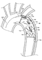
112 ステントグラフト (stent-graft)
120 グラフト (graft)
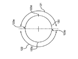
121 半体 (halve)
122 半体 (halve)
123a 接線 (tangent line)
123b 接線 (tangent line)
124 近位部分 (proximal portion)
125 遠位部分 (distal portion)
126 中間部分 (intermediate portion)
130 ステント (stent)
130a ステント (stent)
130b ステント (stent)
130c ステント (stent)
130d ステント (stent)
131 封止ステント (sealing stent)
140 直径減少コネクタ (diameter reducing connector)
140 直径減少タイ (diameter reducing tie)
140a 直径減少コネクタ (diameter reducing connector)
140b 直径減少コネクタ (diameter reducing connector)
140c 直径減少コネクタ (diameter reducing connector)
140d 直径減少コネクタ (diameter reducing connector)
140e 直径減少コネクタ (diameter reducing connector)
140f 直径減少コネクタ (diameter reducing connector)
150 係止部材 (locking member)
151 孔 (aperture)
152 孔 (aperture)
153 孔 (aperture)
154 孔 (aperture)
160 直径減少部材 (diameter reducing member)
162 ギャザー (gather)
170a 穿孔 (fenestration)
170b 穿孔 (fenestration)
170c 穿孔 (fenestration)
170d 穿孔 (fenestration)
180a ローブ (lobe)
180b ローブ (lobe)
180c ローブ (lobe)
1000 ガイドワイヤ (guidewire)
1010 矢印 (arrow)
Claims (21)
- 遠位端部から近位端部に延びるカニューレと、
近位端部から遠位端部に延びる管状のグラフトを含むステントグラフトと、
前記カニューレの前記遠位端部から延びる係止部材と、
前記グラフトの長さに沿って前記カニューレ遠位端部から延びる第一直径減少部材とを含み、
前記グラフトは、近位部分を含み、前記グラフトは、互いに対向して配置される第一及び第二の長手に延びる側部を含み、前記第一及び第二の半体の交差部は、前記グラフトの長さに沿って長手に延びる接線を形成し、
前記係止部材は、係止位置と解放位置との間で移動可能であり、前記係止部材が前記係止位置にあるとき、前記係止部材は、前記グラフトの表面を前記接線に沿って前記カニューレに対して拘束し、前記カニューレの中心軸は、前記グラフトの中心軸から離間し、
前記第一直径減少部材は、前記近位部分内で前記接線に近接して配置される前記グラフトの第一部分に摺動可能に接続され、且つ、前記近位部分内で前記接線から円周方向に離間する位置において配置される前記グラフトの第二部分に摺動可能に接続され、前記第一直径減少部材は、拘束位置と、解放位置とを有し、
前記第一直径減少部材が前記拘束位置にあるとき、前記グラフトの前記第二部分は、前記ステントグラフトの前記近位部分が前記接線及び前記カニューレから離れる方向に延びる少なくとも2つのローブを備える直径減少構造を有するよう、前記グラフトの前記第一部分に向かって引かれ、前記第一直径減少部材が前記解放位置にあるとき、前記第二部分は、前記グラフトの前記第一部分から離れて配置され、それによって、前記グラフトの前記近位部分は、実質的に管状の構造を有する、
供給システム。 - 前記グラフトの長さに沿って前記カニューレの遠位端部から延びる第二直径減少部材を更に含み、該第二直径減少部材は、前記近位部分内で前記接線に近接して配置される前記グラフトの第三部分に摺動可能に接続され、且つ、前記近位部分内で前記接線から円周方向に離間する位置において配置される前記グラフトの第四部分に摺動可能に接続され、前記第二直径減少部材は、拘束位置と、解放位置とを有し、
前記第一及び第二の直径減少部材が前記拘束位置にあるとき、前記グラフトの前記第四部分は、前記ステントグラフトの前記近位部分が前記接線及び前記カニューレから離れる方向に延びる3つのローブを備える直径減少構造を有するよう、前記グラフトの前記第三部分に向かって引かれ、前記第一及び第二の直径減少部材が前記解放位置にあるとき、前記第四部分は、前記グラフトの前記第三部分から離れて配置され、それによって、前記グラフトの前記近位部分は、実質的に管状の構造を有する、
請求項1に記載の供給システム。 - 前記近位部分は、前記グラフトの前記第一側部で前記接線から円周方向に離間する少なくとも1つの第一側部下方穿孔と、前記接線に近接して配置される少なくとも1つの上方穿孔とを含み、
前記第一直径減少部材は、前記グラフトの前記第一側部に沿って延び、
前記第一直径減少部材は、前記下方穿孔を通じ、前記上方穿孔を通じ、そして、前記カニューレの前記近位端部まで延びる、
請求項1に記載の供給システム。 - 前記グラフトの前記第二半体で前記接線から円周方向に離間する少なくとも1つの第二側部下方穿孔と、前記ステントグラフトに摺動可能に接続される第二直径減少部材とを更に含み、前記第二直径減少部材は、前記近位部分において前記グラフトの前記第二半体に沿って、前記第二側部下方穿孔を通じて、前記上方穿孔を通じて、そして、前記カニューレの前記近位端部まで延び、前記第二直径減少部材は、拘束位置と、解放位置との間で移動可能であり、
前記第一及び第二の直径減少部材が前記拘束位置にあるとき、前記第一側部下方穿孔及び前記第二側部下方穿孔に近接して配置される前記グラフトの部分は、前記少なくとも1つの上方穿孔に近接して配置される前記グラフトの部分に向かって引かれ、それによって、前記ステントグラフトの前記近位部分は、少なくとも3つのローブを備える直径減少構造を有する、
請求項3に記載の供給システム。 - 前記少なくとも1つの第一側部下方穿孔は、第一穿孔及び第二穿孔を含み、前記上方穿孔は、第三穿孔及び第四穿孔を含み、
前記第一直径減少部材は、1)前記近位部分において前記グラフトに沿って、2)前記第一穿孔を通じて、3)前記第三穿孔を通じて、4)前記第四穿孔を通じて、5)前記第二穿孔を通じて、そして、6)前記カニューレの前記近位端部まで延びる、
請求項4に記載の供給システム。 - 前記少なくとも1つの第二側部下方穿孔は、第五及び第六の穿孔を含み、前記上方穿孔は、第七及び第八の穿孔を更に含み、
前記第二直径減少部材は、1)前記近位部分において前記グラフトの前記第二側部に沿って、2)前記第五穿孔を通じて、3)前記第七穿孔を通じて、4)前記第八穿孔を通じて、5)前記第六穿孔を通じて、そして、6)前記カニューレの前記近位端部まで延びる、
請求項5に記載の供給システム。 - 前記第一穿孔と前記第二穿孔との間に配置される前記グラフトの部分が、前記グラフトの前記第一側部で約120度だけ前記接線から円周方向に離間し、前記第三穿孔と前記第四穿孔との間に配置される前記グラフトの部分が、前記グラフトの前記第二側部で約120度だけ前記接線から円周方向に離間し、
前記第一及び第二の直径減少部材が前記拘束位置にあるとき、前記3つのローブは、実質的に同じ大きさである、
請求項6に記載の供給システム。 - 前記第一穿孔と前記第二穿孔との間に配置される前記グラフトの部分が、前記第一側部で第一距離だけ前記接線から円周方向に離間し、前記第五穿孔と前記第六穿孔との間に配置される前記グラフトの部分が、前記グラフトの前記第二側部で第二距離だけ前記接線から円周方向に離間する、請求項6に記載の供給システム。
- 前記第一及び第二の距離は、同じであり、前記第一及び第二の距離は、前記グラフトの円周の1/3未満であり、それによって、前記第一及び第二の直径減少部材が前記拘束位置にあるとき、前記接線の反対側に配置される前記グラフトの前記部分を含む前記ローブは、残余の2つのローブよりも大きい、請求項8に記載の供給システム。
- 前記ステントグラフトは、
前記グラフトに取り付けられる支持構造であって、少なくとも第一ステントリングを含み、該ステントリングは、波状パターンで屈曲部によって接続される複数の構造部材を含む支持構造と、
前記第一ステントリングの第一屈曲部に取り付けられる第一直径減少コネクタと、
前記第一ステントリングの第二屈曲部に取り付けられる第二直径減少コネクタとを含み、
前記第一リングは、前記グラフトの中間部分に取り付けられ、
前記第一及び第二の屈曲部は、前記接線から円周方向に離間して、前記グラフトの前記第一側部に配置される、
請求項1に記載の供給システム。 - 前記中間部分において、前記第一直径減少部材は、前記第一直径減少コネクタから前記第二直径減少コネクタに延び、
前記第一直径減少部材が前記拘束位置にあるとき、前記第一屈曲部は円周方向において前記第二屈曲部に向かって引かれ、それによって、前記グラフトの前記第一側部に第一ギャザーを形成し、該第一ギャザーは、前記中間部分において前記ステントグラフトの直径を減少する
請求項10に記載の供給システム。 - 前記グラフトの前記中間部分に取り付けられる第二ステントリングであって、波状パターンで前記屈曲部によって接続される複数の構造部材を含む第二ステントリングと、
該第二ステントリングの第一屈曲部に取り付けられる第三直径減少コネクタと、
前記第二ステントリングの第二屈曲部に取り付けられる第四直径減少コネクタとを更に含み、
前記第二リングは、前記グラフトの前記中間部分に取り付けられ、前記第二リングの前記第一及び第二の屈曲部は、前記接線から円周方向に離間して、前記グラフトの前記第一半体に配置され、
前記中間部分において、前記直径減少部材は、前記第二直径減少コネクタから前記第三直径減少コネクタまで、そして、前記第三直径減少コネクタから前記第四直径減少コネクタまで更に延び、
前記第一直径減少部材が前記拘束位置にあるとき、前記第二ステントリングの前記第一屈曲部は、円周方向において前記第二ステントリングの前記第二屈曲部に向かって引かれ、それによって、前記グラフト内に第二ギャザーを形成し、該第二ギャザーは、前記中間部分において前記ステントグラフトの直径を更に減少する、
請求項11に記載の供給システム。 - 前記第一ステントリングの前記第一及び第二の屈曲部と、前記第二ステントリングの前記第一及び第二の屈曲部は、前記グラフトの前記第一側部で、90〜120度の間、前記接線から円周方向に離間する、
請求項12に記載の供給システム。 - 前記ステントグラフトは、
前記第一ステントリングの第三屈曲部に取り付けられる第五直径減少コネクタと、
前記第一ステントリングの第四屈曲部に取り付けられる第三直径減少コネクタとを更に含み、
前記第一ステントリングの前記第三及び第四の屈曲部は、前記接線から円周方向に離間して、前記グラフトの前記第二半体に配置される、
請求項13に記載の供給システム。 - 前記中間部分において、前記第二直径減少部材は、前記第五直径減少コネクタから前記第六直径減少コネクタまで延び、
前記第二直径減少部材が前記拘束位置にあるとき、前記第一ステントリングの前記第三屈曲部は、円周方向において前記第一ステントリングの前記第四屈曲部に向かって引かれ、それによって、前記グラフト内に第三ギャザーを形成し、該第三ギャザーは、前記中間部分において前記ステントグラフトの直径を更に減少する、
請求項14に記載の供給システム。 - 前記第二ステントリングの第三屈曲部に取り付けられる第七直径減少コネクタと、
前記第二ステントリングの第四屈曲部に取り付けられる第八直径減少コネクタとを更に含み、
前記第二ステントリングの前記第三及び第四の屈曲部は、前記背線から円周方向に離間して、前記グラフトの前記第二半体に配置され、
前記中間部分において、前記第二直径減少部材は、前記第六直径減少コネクタから前記第七直径減少コネクタまで、そして、前記第七直径減少コネクタから前記第八直径減少コネクタまで更に延び、
前記第二直径減少部材が前記拘束位置にあるとき、前記第二ステントリングの前記第三屈曲部は、円周方向に前記第二ステントリングの前記第四屈曲部に向かって引かれ、それによって、前記グラフト内に第四ギャザーを形成し、該第四ギャザーは、前記中間部分において前記ステントグラフトの直径を更に減少する、
請求項15に記載の供給システム。 - 前記第一ステントリングの前記第三及び第四の屈曲部と、前記第二ステントリングの前記第三及び第四の屈曲部とは、前記グラフトの前記第二側部で、90〜120度の間、前記接線から円周方向に離間する、請求項14に記載の供給システム。
- 湾曲した管腔内にステントグラフトを配置する供給システムであって、
前記配置システムは、
遠位端部から近位端部にアーチ構造に延びる湾曲したカニューレと、
管状のグラフトを含むステントグラフトと、
前記カニューレの前記遠位端部から延びる係止部材と、
前記グラフトに沿って前記カニューレの前記遠位端部から延びる第一直径減少部材と、
前記グラフトに沿って前記カニューレの前記遠位端部から延びる第二直径減少部材とを含み、
前記グラフトは、近位部分と、中間部分とを有し、前記グラフトは、互いに対向して配置される第一及び第二の長手に延びる側部を含み、前記第一及び第二の側部の交差部は、前記グラフトの長さに沿って長手に延びる接線を形成し、
前記近位部分は、1)前記グラフトの前記第一側部で前記接線から円周方向に離間する第一と第二の穿孔と、2)前記グラフトの前記第二側部で前記接線から円周方向に離間する第三及び第四の穿孔と、3)前記接線に近接して配置される第五乃至第八の穿孔とを含み、
前記係止部材は、係止位置と、解放位置との間で移動可能であり、前記係止部材が前記係止位置にあるとき、前記係止部材は、前記接線に沿って前記グラフトの表面を前記カニューレに対して拘束し、前記カニューレの中心軸は、前記グラフトの中心軸から離間し、
前記第一直径減少部材は、1)前記近位部分内で前記グラフトに沿って、2)前記第一穿孔を通じて、3)前記第五穿孔を通じて、4)前記第六穿孔を通じて、5)前記第二穿孔を通じて、そして、6)前記カニューレの前記近位端部まで、前記グラフトの前記近位部分内で延び、
前記第二直径減少部材は、1)前記近位部分内で前記第二側部に沿って、2)前記第三穿孔を通じて、3)前記第七穿孔を通じて、4)前記第八穿孔を通じて、5)前記第四穿孔を通じて、そして、6)前記カニューレの前記近位端部まで、前記グラフトの前記近位部分内で延び、
前記第一及び第二の直径減少部材が拘束位置にあるとき、前記第一及び第二の穿孔の間に配置される前記グラフトの部分が、前記第五及び第六の穿孔の間に配置される前記グラフトの部分に向かって引かれ、前記第三及び第四の穿孔の間に配置される前記グラフトの部分が、前記第七及び第八の穿孔の間に配置される前記グラフトの部分に向かって引かれ、それによって、前記ステントグラフトの前記近位部分は、3つのローブを備える直径減少構造を有する、
供給システム。 - 前記グラフトに取り付けられる支持構造であって、少なくとも第一ステントリングを含み、該第一ステントリングは、波状パターンにおいて屈曲部によって接続される複数の構造部材を含む支持構造と、
前記第一ステントリングの第一屈曲部に取り付けられる第一直径減少コネクタと、
前記第一ステントリングの第二屈曲部に取り付けられる第二直径減少コネクタと、
前記第一ステントリングの第三屈曲部に取り付けられる第三直径減少コネクタと、
前記第一ステントリングの第四屈曲部に取り付けられる第四直径減少コネクタとを含み
前記第一ステントリングは、前記グラフトの前記中間部分に取り付けられ、前記第一及び第二の屈曲部は、前記接線から円周方向に離間して、前記グラフトの前記第一半体に配置され、前記第三及び第四の屈曲部は、前記接線から円周方向に離間して、前記グラフトの前記第二半体に配置され、
前記中間部分において、前記第一直径減少部材は、前記グラフトの前記第二側部に沿って、前記第三又は第四の直径減少コネクタの一方に延び、更に、前記第一又は第二の直径減少コネクタの一方に更に延び、前記第二直径減少部材は、前記グラフトの前記第一側部に沿って、前記第一又は第二の直径減少コネクタの他方から前記第一又は第二の直径減少コネクタの他方に延び、
前記第一及び第二の直径減少部材が前記拘束位置にあるとき、前記第一及び第二の屈曲部は、前記第三及び第四の屈曲部に向かって引かれ、それによって、前記グラフト内に少なくとも1つのギャザーを形成し、該ギャザーは、前記中間部分において前記ステントグラフトの直径を減少する、
請求項18に記載の供給システム。 - 前記第一及び第二の穿孔の間に配置される前記グラフトの前記部分は、前記グラフトの前記第一側部で、約120度だけ前記接線から円周方向に離間し、前記第三及び第四の穿孔の間に配置される前記グラフトの前記部分は、前記グラフトの前記第二側部で、約120度だけ前記接線から円周方向に離間し、前記第一及び第二の直径減少部材が前記拘束位置にあるとき、前記3つのローブは、実質的に同じ大きさである、請求項19に記載の供給システム。
- 損傷した或いは疾病のある管を修復する方法であって、
供給システムを提供することを含み、
前記供給システムは、
遠位端部から近位端部に延びるカニューレと、
近位端部から遠位端部に延びる管状のグラフトと、
前記カニューレの前記遠位端部から延びる係止部材と、
前記グラフトの長さに沿って前記カニューレの遠位端部から延びる直径減少部材とを含み、
前記グラフトは、近位部分を含み、前記グラフトは、互いに対向して配置される第一及び第二の長手に延びる側部を含み、前記第一及び第二の半体の交差部は、前記グラフトの長さに沿って長手に延びる接線を形成し、
前記係止部材は、係止位置と、解放位置との間で移動可能であり、
前記直径減少部材は、前記近位部分において前記接線に近接して配置される前記グラフトの第一部分に摺動可能に接続され、前記近位部分において前記接線から円周方向に離間する位置に配置され、前記直径減少部材は、拘束位置と、解放位置とを有し、
当該方法は、
前記接線に沿って前記グラフトの表面を前記カニューレに対して拘束し、且つ、前記係止部材を前記係止構造に移動することによって、前記グラフトの中心軸から離れる方向に前記カニューレの中心軸を移動すること、
前記第一直径減少部材を前記拘束位置に移動し、且つ、前記グラフトの前記第二部分を前記グラフトの前記第一部分に向かって引くことによって、少なくとも2つのローブを有する前記ステントグラフトの前記近位部分内に直径減少構造を形成すること、
前記供給システムを湾曲した管腔内に前進させること、及び、
前記直径減少部材を前記解放位置に移動させることを含み、
それによって、前記ステントグラフトの前記近位部分は、前記直径減少構造から解放され、前記ステントグラフトの前記近位部分は、実質的に管状の構造を取る、
方法。
Applications Claiming Priority (2)
| Application Number | Priority Date | Filing Date | Title |
|---|---|---|---|
| US201061429081P | 2010-12-31 | 2010-12-31 | |
| US61/429,081 | 2010-12-31 |
Publications (2)
| Publication Number | Publication Date |
|---|---|
| JP2012139500A true JP2012139500A (ja) | 2012-07-26 |
| JP6100995B2 JP6100995B2 (ja) | 2017-03-22 |
Family
ID=45442982
Family Applications (1)
| Application Number | Title | Priority Date | Filing Date |
|---|---|---|---|
| JP2011284584A Active JP6100995B2 (ja) | 2010-12-31 | 2011-12-27 | 形状適合プロステーシス供給システム及びその配置方法 |
Country Status (3)
| Country | Link |
|---|---|
| US (1) | US9198787B2 (ja) |
| EP (1) | EP2471498B1 (ja) |
| JP (1) | JP6100995B2 (ja) |
Cited By (6)
| Publication number | Priority date | Publication date | Assignee | Title |
|---|---|---|---|---|
| WO2019103147A1 (ja) * | 2017-11-24 | 2019-05-31 | 有限会社Ptmc研究所 | 人工血管搬送装置 |
| WO2019103148A1 (ja) * | 2017-11-24 | 2019-05-31 | 有限会社Ptmc研究所 | 人工血管搬送装置 |
| JP2020508088A (ja) * | 2017-02-24 | 2020-03-19 | ボルトン メディカル インコーポレイテッド | 半径方向に調整可能なステントグラフト送達システム |
| JP2020508085A (ja) * | 2017-02-24 | 2020-03-19 | ボルトン メディカル インコーポレイテッド | ステントグラフトを半径方向に収縮するための送達システムおよび使用方法 |
| JP2021511088A (ja) * | 2017-12-01 | 2021-05-06 | シー・アール・バード・インコーポレーテッドC R Bard Incorporated | 独自に内径を縮小させるための調整可能な血管移植片および関連する方法 |
| JP2021184831A (ja) * | 2015-09-18 | 2021-12-09 | Sbカワスミ株式会社 | ステントグラフト |
Families Citing this family (85)
| Publication number | Priority date | Publication date | Assignee | Title |
|---|---|---|---|---|
| US7147661B2 (en) | 2001-12-20 | 2006-12-12 | Boston Scientific Santa Rosa Corp. | Radially expandable stent |
| CA2725736C (en) | 2008-06-04 | 2013-09-17 | Gore Enterprise Holdings, Inc. | Controlled deployable medical device and method of making the same |
| CA2727000C (en) | 2008-06-04 | 2014-01-07 | Gore Enterprise Holdings, Inc. | Controlled deployable medical device and method of making the same |
| US8137398B2 (en) * | 2008-10-13 | 2012-03-20 | Medtronic Ventor Technologies Ltd | Prosthetic valve having tapered tip when compressed for delivery |
| US8858610B2 (en) | 2009-01-19 | 2014-10-14 | W. L. Gore & Associates, Inc. | Forced deployment sequence |
| WO2011064782A2 (en) | 2009-11-30 | 2011-06-03 | Endospan Ltd. | Multi-component stent-graft system for implantation in a blood vessel with multiple branches |
| US9744033B2 (en) | 2011-04-01 | 2017-08-29 | W.L. Gore & Associates, Inc. | Elastomeric leaflet for prosthetic heart valves |
| US10117765B2 (en) | 2011-06-14 | 2018-11-06 | W.L. Gore Associates, Inc | Apposition fiber for use in endoluminal deployment of expandable implants |
| US9554806B2 (en) | 2011-09-16 | 2017-01-31 | W. L. Gore & Associates, Inc. | Occlusive devices |
| US9662196B2 (en) | 2011-09-27 | 2017-05-30 | Cook Medical Technologies Llc | Endoluminal prosthesis with steerable branch |
| CA2855387C (en) | 2011-11-10 | 2020-08-04 | Transaortic Medical, Inc. | System for deploying a device to a distal location across a diseased vessel |
| US9782282B2 (en) | 2011-11-14 | 2017-10-10 | W. L. Gore & Associates, Inc. | External steerable fiber for use in endoluminal deployment of expandable devices |
| US9877858B2 (en) | 2011-11-14 | 2018-01-30 | W. L. Gore & Associates, Inc. | External steerable fiber for use in endoluminal deployment of expandable devices |
| WO2013084235A2 (en) * | 2011-12-04 | 2013-06-13 | Endospan Ltd. | Branched stent-graft system |
| US9375308B2 (en) | 2012-03-13 | 2016-06-28 | W. L. Gore & Associates, Inc. | External steerable fiber for use in endoluminal deployment of expandable devices |
| US8968384B2 (en) * | 2012-04-27 | 2015-03-03 | Medtronic Vascular, Inc. | Circumferentially constraining sutures for a stent-graft |
| US9283072B2 (en) | 2012-07-25 | 2016-03-15 | W. L. Gore & Associates, Inc. | Everting transcatheter valve and methods |
| US10376360B2 (en) | 2012-07-27 | 2019-08-13 | W. L. Gore & Associates, Inc. | Multi-frame prosthetic valve apparatus and methods |
| US9144492B2 (en) | 2012-12-19 | 2015-09-29 | W. L. Gore & Associates, Inc. | Truncated leaflet for prosthetic heart valves, preformed valve |
| US10966820B2 (en) | 2012-12-19 | 2021-04-06 | W. L. Gore & Associates, Inc. | Geometric control of bending character in prosthetic heart valve leaflets |
| US9737398B2 (en) | 2012-12-19 | 2017-08-22 | W. L. Gore & Associates, Inc. | Prosthetic valves, frames and leaflets and methods thereof |
| US10039638B2 (en) | 2012-12-19 | 2018-08-07 | W. L. Gore & Associates, Inc. | Geometric prosthetic heart valves |
| US10321986B2 (en) | 2012-12-19 | 2019-06-18 | W. L. Gore & Associates, Inc. | Multi-frame prosthetic heart valve |
| US9968443B2 (en) | 2012-12-19 | 2018-05-15 | W. L. Gore & Associates, Inc. | Vertical coaptation zone in a planar portion of prosthetic heart valve leaflet |
| EP2745812B1 (en) * | 2012-12-19 | 2017-01-18 | Cook Medical Technologies LLC | Repositionable diameter constraints |
| US9101469B2 (en) | 2012-12-19 | 2015-08-11 | W. L. Gore & Associates, Inc. | Prosthetic heart valve with leaflet shelving |
| US10350096B2 (en) | 2012-12-26 | 2019-07-16 | Cook Medical Technologies Llc | Expandable stent-graft system having diameter reducing connectors |
| WO2014108895A2 (en) | 2013-01-08 | 2014-07-17 | Endospan Ltd. | Minimization of stent-graft migration during implantation |
| US9668892B2 (en) | 2013-03-11 | 2017-06-06 | Endospan Ltd. | Multi-component stent-graft system for aortic dissections |
| AU2014262488B2 (en) * | 2013-05-10 | 2018-08-30 | Medtronic, Inc. | System for deploying a device to a distal location across a diseased vessel |
| US11911258B2 (en) | 2013-06-26 | 2024-02-27 | W. L. Gore & Associates, Inc. | Space filling devices |
| DE102013018426A1 (de) * | 2013-11-04 | 2015-05-07 | Bentley Innomed Gmbh | Stent mit Rückhalteelement |
| US10603197B2 (en) | 2013-11-19 | 2020-03-31 | Endospan Ltd. | Stent system with radial-expansion locking |
| CN106659567B (zh) | 2014-08-18 | 2019-06-14 | W.L.戈尔及同仁股份有限公司 | 带有用于假体瓣膜的一体缝合封套的框架 |
| US9827094B2 (en) | 2014-09-15 | 2017-11-28 | W. L. Gore & Associates, Inc. | Prosthetic heart valve with retention elements |
| EP3068339B1 (en) | 2014-12-18 | 2017-11-01 | Endospan Ltd. | Endovascular stent-graft with fatigue-resistant lateral tube |
| EP3040056B1 (en) * | 2014-12-29 | 2019-09-11 | Cook Medical Technologies LLC | Prosthesis deployment system |
| EP3632376B1 (en) | 2015-01-12 | 2024-03-06 | Endospan Ltd. | Self-curving stent graft |
| US10426646B2 (en) * | 2015-03-05 | 2019-10-01 | Cook Medical Technologies Llc | Pre-loaded delivery device with tri-fold proximal prosthesis attachment |
| US10478591B2 (en) | 2015-03-05 | 2019-11-19 | Cook Medical Technologies Llc | Stent graft delivery device pre-loaded with a single wire for device tracking and cannulation |
| CN104706448B (zh) * | 2015-03-26 | 2017-03-08 | 黄连军 | 覆膜支架以及覆膜支架用输送系统 |
| CN114652385A (zh) | 2015-05-14 | 2022-06-24 | W.L.戈尔及同仁股份有限公司 | 用于闭塞心耳的装置 |
| US10765539B2 (en) * | 2015-05-27 | 2020-09-08 | W. L. Gore & Associates, Inc. | Stent graft device with anchoring members having adjustable geometries |
| US10188538B2 (en) * | 2015-12-30 | 2019-01-29 | Cook Medical Technologies Llc | Hybrid trigger wire for endografts |
| CN105726165B (zh) * | 2016-05-09 | 2017-07-28 | 中国人民解放军南京军区福州总医院 | 一种主动脉覆膜分支支架 |
| ES3041086T3 (en) | 2016-06-13 | 2025-11-06 | Bolton Medical Inc | Devices for reinforcing fenestrations in prosthetic implants |
| US10433991B2 (en) * | 2016-07-18 | 2019-10-08 | Cook Medical Technologies Llc | Controlled expansion stent graft delivery system |
| US10327935B2 (en) * | 2016-07-21 | 2019-06-25 | Cook Medical Technologies Llc | Stent graft with internal constraining mechanism |
| CN109789009B (zh) | 2016-08-02 | 2021-04-16 | 主动脉公司 | 用于将假体植入物联接到开窗体的系统、装置和方法 |
| US11191632B2 (en) | 2016-11-10 | 2021-12-07 | Cook Medical Technologies Llc | Temporary diameter reduction constraint arrangement for a stent graft in combination with a stent graft |
| EP3320881B1 (en) * | 2016-11-10 | 2019-09-04 | Cook Medical Technologies LLC | Diameter reduction constraint arrangement for a stent graft in combination with a stent graft |
| US10463517B2 (en) * | 2017-01-16 | 2019-11-05 | Cook Medical Technologies Llc | Controlled expansion stent graft delivery system |
| WO2018156851A1 (en) | 2017-02-24 | 2018-08-30 | Bolton Medical, Inc. | Vascular prosthesis with moveable fenestration |
| JP7479844B2 (ja) * | 2017-02-24 | 2024-05-09 | ボルトン メディカル インコーポレイテッド | 束縛可能なステントグラフト、送達システムおよび使用方法 |
| WO2018156848A1 (en) | 2017-02-24 | 2018-08-30 | Bolton Medical, Inc. | Vascular prosthesis with crimped adapter and methods of use |
| JP7112393B2 (ja) | 2017-02-24 | 2022-08-03 | ボルトン メディカル インコーポレイテッド | シースが収縮されたステントグラフト送達システムおよび使用方法 |
| ES2993582T3 (en) * | 2017-02-24 | 2025-01-02 | Bolton Medical Inc | System to radially constrict a stent graft |
| WO2018156849A1 (en) | 2017-02-24 | 2018-08-30 | Bolton Medical, Inc. | Vascular prosthesis with fenestration ring and methods of use |
| WO2018156847A1 (en) | 2017-02-24 | 2018-08-30 | Bolton Medical, Inc. | Delivery system and method to radially constrict a stent graft |
| WO2018156850A1 (en) | 2017-02-24 | 2018-08-30 | Bolton Medical, Inc. | Stent graft with fenestration lock |
| AU2018230960B2 (en) | 2017-03-08 | 2020-07-09 | W. L. Gore & Associates, Inc. | Steering wire attach for angulation |
| US10709541B2 (en) | 2017-04-28 | 2020-07-14 | Cook Medical Technologies Llc | Systems and methods for adjusting the diameter of an endoluminal prosthesis and an endoluminal prosthesis configured for the same |
| JP6979122B2 (ja) * | 2017-08-28 | 2021-12-08 | コンメッド コーポレーション | 軟組織移植片を調製するためのシステムおよび方法 |
| EP3681440A1 (en) | 2017-09-12 | 2020-07-22 | W. L. Gore & Associates, Inc. | Leaflet frame attachment for prosthetic valves |
| WO2019060816A2 (en) | 2017-09-25 | 2019-03-28 | Aortica Corporation | SYSTEMS, DEVICES AND METHODS FOR COUPLING PROSTHETIC IMPLANT TO A FENCED BODY |
| JP6875601B2 (ja) | 2017-09-27 | 2021-05-26 | ダブリュ.エル.ゴア アンド アソシエイツ,インコーポレイティドW.L. Gore & Associates, Incorporated | リーフレットが機械的にカップリングされた人工弁 |
| EP3687451B1 (en) | 2017-09-27 | 2023-12-13 | Edwards Lifesciences Corporation | Prosthetic valve with expandable frame |
| CA3078699C (en) | 2017-10-13 | 2023-10-10 | W.L. Gore & Associates, Inc. | Telescoping prosthetic valve and delivery system |
| US11173023B2 (en) | 2017-10-16 | 2021-11-16 | W. L. Gore & Associates, Inc. | Medical devices and anchors therefor |
| US11154397B2 (en) | 2017-10-31 | 2021-10-26 | W. L. Gore & Associates, Inc. | Jacket for surgical heart valve |
| JP7072062B2 (ja) | 2017-10-31 | 2022-05-19 | ダブリュ.エル.ゴア アンド アソシエイツ,インコーポレイティド | 経カテーテル留置システム及び関連する方法 |
| EP3703618A1 (en) | 2017-10-31 | 2020-09-09 | W. L. Gore & Associates, Inc. | Prosthetic heart valve |
| US11439502B2 (en) | 2017-10-31 | 2022-09-13 | W. L. Gore & Associates, Inc. | Medical valve and leaflet promoting tissue ingrowth |
| ES2910187T3 (es) * | 2017-10-31 | 2022-05-11 | Bolton Medical Inc | Componente de torque distal, sistema de colocación y método de uso del mismo |
| CN109984862B (zh) * | 2017-12-29 | 2025-10-03 | 杭州唯强医疗科技有限公司 | 一种可分步释放的主动脉覆膜支架 |
| AU2018438636B2 (en) | 2018-08-31 | 2022-06-30 | W. L. Gore & Associates, Inc. | Apparatus, system, and method for steering an implantable medical device |
| EP3843659A1 (en) | 2018-08-31 | 2021-07-07 | W.L. Gore & Associates, Inc. | Apparatus, system, and method for steering an implantable medical device |
| USD926322S1 (en) | 2018-11-07 | 2021-07-27 | W. L. Gore & Associates, Inc. | Heart valve cover |
| US11497601B2 (en) | 2019-03-01 | 2022-11-15 | W. L. Gore & Associates, Inc. | Telescoping prosthetic valve with retention element |
| EP3952790A1 (en) | 2019-04-12 | 2022-02-16 | W.L. Gore & Associates, Inc. | Valve with multi-part frame and associated resilient bridging features |
| WO2021129286A1 (zh) * | 2019-12-23 | 2021-07-01 | 杭州唯强医疗科技有限公司 | 覆膜支架系统及其覆膜支架 |
| GB2605559B (en) | 2021-01-07 | 2023-04-05 | Cook Medical Technologies Llc | Stent graft |
| AU2021201336B1 (en) | 2021-03-02 | 2021-07-15 | Cook Medical Technologies Llc | A constraint arrangement for a stent-graft loaded onto a delivery system |
| EP4356875A1 (en) | 2022-10-17 | 2024-04-24 | Cook Medical Technologies LLC | Stent graft assembly |
| CN121081178B (zh) * | 2025-11-11 | 2026-02-27 | 北京华脉泰科医疗器械股份有限公司 | 一种输送系统及覆膜支架组件 |
Citations (8)
| Publication number | Priority date | Publication date | Assignee | Title |
|---|---|---|---|---|
| JPH06503734A (ja) * | 1990-11-26 | 1994-04-28 | シュトレッカー,エルンスト ペーター | 患者の身体に内植可能なプロテーゼを有する装置 |
| US20040073289A1 (en) * | 2002-08-23 | 2004-04-15 | William A. Cook Australia Pty. Ltd. | Asymmetric stent graft attachment |
| US20070088424A1 (en) * | 2005-09-21 | 2007-04-19 | William A. Cook Australia Pty Ltd. | Endoluminal delivery assembly |
| JP2009504352A (ja) * | 2005-08-18 | 2009-02-05 | ウィリアム・エイ・クック・オーストラリア・プロプライエタリー・リミテッド | ステントグラフトのアセンブリ |
| US20090259291A1 (en) * | 2008-04-09 | 2009-10-15 | William Cook Europe Aps | Stent-graft and apparatus and fitting method |
| US20100114290A1 (en) * | 2008-10-31 | 2010-05-06 | William Cook Europe Aps | Introducer for Deploying a Stent Graft in a Curved Lumen |
| US20100114291A1 (en) * | 2008-10-31 | 2010-05-06 | William Cook Europe Aps | Introducer for Deploying a Stent Graft in a Curved Lumen and Stent Graft Therefor |
| JP2010526586A (ja) * | 2007-05-11 | 2010-08-05 | ウィリアム・エイ・クック・オーストラリア・プロプライエタリー・リミテッド | 胸部大動脈用ステントグラフト |
Family Cites Families (29)
| Publication number | Priority date | Publication date | Assignee | Title |
|---|---|---|---|---|
| US4861830A (en) | 1980-02-29 | 1989-08-29 | Th. Goldschmidt Ag | Polymer systems suitable for blood-contacting surfaces of a biomedical device, and methods for forming |
| US4675361A (en) | 1980-02-29 | 1987-06-23 | Thoratec Laboratories Corp. | Polymer systems suitable for blood-contacting surfaces of a biomedical device, and methods for forming |
| US4502159A (en) | 1982-08-12 | 1985-03-05 | Shiley Incorporated | Tubular prostheses prepared from pericardial tissue |
| US5693083A (en) * | 1983-12-09 | 1997-12-02 | Endovascular Technologies, Inc. | Thoracic graft and delivery catheter |
| US5017664A (en) | 1987-06-03 | 1991-05-21 | Wisconsin Alumni Research Foundation | Biocompatible polyurethane devices wherein polyurethane is modified with lower alkyl sulfonate and lower alkyl carboxylate |
| US4902508A (en) | 1988-07-11 | 1990-02-20 | Purdue Research Foundation | Tissue graft composition |
| US5380304A (en) | 1991-08-07 | 1995-01-10 | Cook Incorporated | Flexible, kink-resistant, introducer sheath and method of manufacture |
| EP1010406B1 (en) * | 1994-06-08 | 2005-02-02 | Cardiovascular Concepts, Inc. | Endoluminal graft |
| US6331188B1 (en) | 1994-08-31 | 2001-12-18 | Gore Enterprise Holdings, Inc. | Exterior supported self-expanding stent-graft |
| US6015429A (en) | 1994-09-08 | 2000-01-18 | Gore Enterprise Holdings, Inc. | Procedures for introducing stents and stent-grafts |
| US5733337A (en) | 1995-04-07 | 1998-03-31 | Organogenesis, Inc. | Tissue repair fabric |
| SK22499A3 (en) | 1996-08-23 | 1999-10-08 | Cook Biotech Inc | Graft prosthesis, materials and methods |
| US6666892B2 (en) | 1996-08-23 | 2003-12-23 | Cook Biotech Incorporated | Multi-formed collagenous biomaterial medical device |
| AU732726B2 (en) | 1996-12-10 | 2001-04-26 | Purdue Research Foundation | Biomaterial derived from vertebrate liver tissue |
| ATE249182T1 (de) | 1996-12-10 | 2003-09-15 | Purdue Research Foundation | Rohrförmige transplantatkonstruktionen aus submucosalem gewebe |
| AU5615400A (en) | 1999-06-18 | 2001-01-09 | Prodesco, Inc. | Attachment tether for stent grafts |
| EP1265667B1 (en) | 2000-03-23 | 2007-05-30 | Cook Incorporated | Catheter introducer sheath |
| ATE459305T1 (de) | 2000-03-30 | 2010-03-15 | Teramed Corp | Verzweigtes transplantat |
| US6939377B2 (en) | 2000-08-23 | 2005-09-06 | Thoratec Corporation | Coated vascular grafts and methods of use |
| US20020187288A1 (en) | 2001-06-11 | 2002-12-12 | Advanced Cardiovascular Systems, Inc. | Medical device formed of silicone-polyurethane |
| US6752826B2 (en) | 2001-12-14 | 2004-06-22 | Thoratec Corporation | Layered stent-graft and methods of making the same |
| EP1471952B1 (en) | 2002-02-05 | 2010-07-21 | Thoratec Corporation | Coated vascular prosthesis and methods of manufacture and use. |
| AU2002951147A0 (en) * | 2002-09-02 | 2002-09-19 | Cook Incorporated | Branch grafting device and method |
| US7101390B2 (en) * | 2003-05-27 | 2006-09-05 | Scimed Life Systems, Inc. | Staged deployment endograft |
| WO2005034811A1 (en) | 2003-10-10 | 2005-04-21 | William Cook Europe Aps | Stent graft retention system |
| US7998186B2 (en) | 2003-10-14 | 2011-08-16 | William A. Cook Australia Pty. Ltd. | Introducer for a side branch device |
| ATE464864T1 (de) | 2003-10-15 | 2010-05-15 | Cook Inc | Haltevorrichtung für ein prothesenablagesystem |
| EP1765221A1 (en) * | 2004-06-16 | 2007-03-28 | Cook Incorporated | Thoracic deployment device and stent graft |
| US7758626B2 (en) | 2004-07-20 | 2010-07-20 | Medtronic Vascular, Inc. | Device and method for delivering an endovascular stent-graft having a longitudinally unsupported portion |
-
2011
- 2011-12-20 US US13/331,935 patent/US9198787B2/en active Active
- 2011-12-21 EP EP11275167.2A patent/EP2471498B1/en active Active
- 2011-12-27 JP JP2011284584A patent/JP6100995B2/ja active Active
Patent Citations (8)
| Publication number | Priority date | Publication date | Assignee | Title |
|---|---|---|---|---|
| JPH06503734A (ja) * | 1990-11-26 | 1994-04-28 | シュトレッカー,エルンスト ペーター | 患者の身体に内植可能なプロテーゼを有する装置 |
| US20040073289A1 (en) * | 2002-08-23 | 2004-04-15 | William A. Cook Australia Pty. Ltd. | Asymmetric stent graft attachment |
| JP2009504352A (ja) * | 2005-08-18 | 2009-02-05 | ウィリアム・エイ・クック・オーストラリア・プロプライエタリー・リミテッド | ステントグラフトのアセンブリ |
| US20070088424A1 (en) * | 2005-09-21 | 2007-04-19 | William A. Cook Australia Pty Ltd. | Endoluminal delivery assembly |
| JP2010526586A (ja) * | 2007-05-11 | 2010-08-05 | ウィリアム・エイ・クック・オーストラリア・プロプライエタリー・リミテッド | 胸部大動脈用ステントグラフト |
| US20090259291A1 (en) * | 2008-04-09 | 2009-10-15 | William Cook Europe Aps | Stent-graft and apparatus and fitting method |
| US20100114290A1 (en) * | 2008-10-31 | 2010-05-06 | William Cook Europe Aps | Introducer for Deploying a Stent Graft in a Curved Lumen |
| US20100114291A1 (en) * | 2008-10-31 | 2010-05-06 | William Cook Europe Aps | Introducer for Deploying a Stent Graft in a Curved Lumen and Stent Graft Therefor |
Cited By (18)
| Publication number | Priority date | Publication date | Assignee | Title |
|---|---|---|---|---|
| JP2021184831A (ja) * | 2015-09-18 | 2021-12-09 | Sbカワスミ株式会社 | ステントグラフト |
| JP7185739B2 (ja) | 2015-09-18 | 2022-12-07 | Sbカワスミ株式会社 | ステントグラフト |
| JP7042259B2 (ja) | 2017-02-24 | 2022-03-25 | ボルトン メディカル インコーポレイテッド | ステントグラフトを半径方向に収縮するための送達システム |
| JP7065091B2 (ja) | 2017-02-24 | 2022-05-11 | ボルトン メディカル インコーポレイテッド | 半径方向に調整可能なステントグラフト送達システム |
| JP7434392B2 (ja) | 2017-02-24 | 2024-02-20 | ボルトン メディカル インコーポレイテッド | ステントグラフトを半径方向に収縮するための送達システム |
| JP2020508085A (ja) * | 2017-02-24 | 2020-03-19 | ボルトン メディカル インコーポレイテッド | ステントグラフトを半径方向に収縮するための送達システムおよび使用方法 |
| JP2022071214A (ja) * | 2017-02-24 | 2022-05-13 | ボルトン メディカル インコーポレイテッド | ステントグラフトを半径方向に収縮するための送達システム |
| JP2020508088A (ja) * | 2017-02-24 | 2020-03-19 | ボルトン メディカル インコーポレイテッド | 半径方向に調整可能なステントグラフト送達システム |
| WO2019103148A1 (ja) * | 2017-11-24 | 2019-05-31 | 有限会社Ptmc研究所 | 人工血管搬送装置 |
| WO2019103147A1 (ja) * | 2017-11-24 | 2019-05-31 | 有限会社Ptmc研究所 | 人工血管搬送装置 |
| JPWO2019103148A1 (ja) * | 2017-11-24 | 2020-11-26 | 有限会社Ptmc研究所 | 人工血管搬送装置 |
| JP7194446B2 (ja) | 2017-11-24 | 2022-12-22 | 有限会社Ptmc研究所 | 人工血管搬送装置 |
| US11648137B2 (en) | 2017-11-24 | 2023-05-16 | Ptmc Institute | Stent graft transport device |
| JP7329247B2 (ja) | 2017-11-24 | 2023-08-18 | 有限会社Ptmc研究所 | 人工血管搬送装置 |
| US11786387B2 (en) | 2017-11-24 | 2023-10-17 | Ptmc Institute | Stent graft transport device |
| JPWO2019103147A1 (ja) * | 2017-11-24 | 2020-10-01 | 有限会社Ptmc研究所 | 人工血管搬送装置 |
| JP2021511088A (ja) * | 2017-12-01 | 2021-05-06 | シー・アール・バード・インコーポレーテッドC R Bard Incorporated | 独自に内径を縮小させるための調整可能な血管移植片および関連する方法 |
| JP7090156B2 (ja) | 2017-12-01 | 2022-06-23 | シー・アール・バード・インコーポレーテッド | 人工医療デバイス |
Also Published As
| Publication number | Publication date |
|---|---|
| US20120172965A1 (en) | 2012-07-05 |
| US9198787B2 (en) | 2015-12-01 |
| EP2471498B1 (en) | 2018-01-17 |
| JP6100995B2 (ja) | 2017-03-22 |
| EP2471498A1 (en) | 2012-07-04 |
Similar Documents
| Publication | Publication Date | Title |
|---|---|---|
| JP6100995B2 (ja) | 形状適合プロステーシス供給システム及びその配置方法 | |
| US12133793B2 (en) | Endoluminal prosthesis having multiple branches or fenestrations and methods of deployment | |
| JP6353593B2 (ja) | 向きを変えられる分岐部を備えた管腔内人工器官 | |
| US10806563B2 (en) | Preloaded wire for endoluminal device | |
| AU2013273638B9 (en) | Preloaded wire for endoluminal device | |
| EP2749251B1 (en) | Expandable stent-graft system having diameter reducing connectors | |
| JP5087397B2 (ja) | 長さ方向に支持されていない部分を有する血管内ステント−移植片を送出すための装置および方法 | |
| EP2606851B1 (en) | Preloaded wire for endoluminal device | |
| JP2014124531A (ja) | モジュール式の分枝部を有する管腔内人工器官および展開方法 | |
| CN112702980A (zh) | 具有锁定线材内腔的低轮廓递送系统 | |
| AU2015261727B2 (en) | Preloaded wire for endoluminal device |
Legal Events
| Date | Code | Title | Description |
|---|---|---|---|
| A621 | Written request for application examination |
Free format text: JAPANESE INTERMEDIATE CODE: A621 Effective date: 20141219 |
|
| RD02 | Notification of acceptance of power of attorney |
Free format text: JAPANESE INTERMEDIATE CODE: A7422 Effective date: 20150227 |
|
| RD04 | Notification of resignation of power of attorney |
Free format text: JAPANESE INTERMEDIATE CODE: A7424 Effective date: 20150313 |
|
| RD04 | Notification of resignation of power of attorney |
Free format text: JAPANESE INTERMEDIATE CODE: A7424 Effective date: 20150319 |
|
| A977 | Report on retrieval |
Free format text: JAPANESE INTERMEDIATE CODE: A971007 Effective date: 20151113 |
|
| A131 | Notification of reasons for refusal |
Free format text: JAPANESE INTERMEDIATE CODE: A131 Effective date: 20151124 |
|
| A521 | Request for written amendment filed |
Free format text: JAPANESE INTERMEDIATE CODE: A523 Effective date: 20160223 |
|
| A131 | Notification of reasons for refusal |
Free format text: JAPANESE INTERMEDIATE CODE: A131 Effective date: 20160524 |
|
| TRDD | Decision of grant or rejection written | ||
| A01 | Written decision to grant a patent or to grant a registration (utility model) |
Free format text: JAPANESE INTERMEDIATE CODE: A01 Effective date: 20170131 |
|
| A61 | First payment of annual fees (during grant procedure) |
Free format text: JAPANESE INTERMEDIATE CODE: A61 Effective date: 20170224 |
|
| R150 | Certificate of patent or registration of utility model |
Ref document number: 6100995 Country of ref document: JP Free format text: JAPANESE INTERMEDIATE CODE: R150 |
|
| R250 | Receipt of annual fees |
Free format text: JAPANESE INTERMEDIATE CODE: R250 |
|
| R250 | Receipt of annual fees |
Free format text: JAPANESE INTERMEDIATE CODE: R250 |
|
| R250 | Receipt of annual fees |
Free format text: JAPANESE INTERMEDIATE CODE: R250 |
|
| R250 | Receipt of annual fees |
Free format text: JAPANESE INTERMEDIATE CODE: R250 |
|
| R250 | Receipt of annual fees |
Free format text: JAPANESE INTERMEDIATE CODE: R250 |
|
| R250 | Receipt of annual fees |
Free format text: JAPANESE INTERMEDIATE CODE: R250 |
|
| R250 | Receipt of annual fees |
Free format text: JAPANESE INTERMEDIATE CODE: R250 |