JP2012140761A - Track bed ballast scraping-out chain - Google Patents
Track bed ballast scraping-out chain Download PDFInfo
- Publication number
- JP2012140761A JP2012140761A JP2010292356A JP2010292356A JP2012140761A JP 2012140761 A JP2012140761 A JP 2012140761A JP 2010292356 A JP2010292356 A JP 2010292356A JP 2010292356 A JP2010292356 A JP 2010292356A JP 2012140761 A JP2012140761 A JP 2012140761A
- Authority
- JP
- Japan
- Prior art keywords
- plate
- ballast
- scraping
- chain
- plates
- Prior art date
- Legal status (The legal status is an assumption and is not a legal conclusion. Google has not performed a legal analysis and makes no representation as to the accuracy of the status listed.)
- Granted
Links
Images


Landscapes
- Machines For Laying And Maintaining Railways (AREA)
Abstract
【課題】 バラスト等掻出し操作時に生じるバラスト等例からの負荷荷重を、できるだけ低減させてチェーンの、すなわちリンクプレートの移動が比較的円滑に行える道床バラスト掻出し用チェーンを提供する。
【解決手段】 道床バラスト掻出し用のビット3を備えた外リンクプレート2の一対の外プレート23,23間に内リンクプレート1の内プレート13を介在させて、これらをジョイントピン6で互いに回動自在に連結して前記内外のリンクプレート1,2を隔置きに連結して成り、前記内プレート13に設けた嵌合透孔13a内に球面軸受4を嵌合する。そして、該球面軸受4に、前記内リンクプレート13を挟んで前記内外のリンクプレート1,2間に介在させたダストカバー5を通じて挿通させた前記ジョイントピン6の両端を、前記外プレートに止着する。
【選択図】 図1PROBLEM TO BE SOLVED: To provide a roadbed ballast scraping chain capable of relatively smoothly moving a chain, that is, a link plate, by reducing a load applied from an example of ballast or the like generated during a ballast scraping operation.
SOLUTION: An inner plate 13 of an inner link plate 1 is interposed between a pair of outer plates 23, 23 of an outer link plate 2 having a bit 3 for scraping a roadbed ballast, and these are rotated by a joint pin 6 with each other. The inner and outer link plates 1 and 2 are connected to each other in a movable manner, and the spherical bearing 4 is fitted into a fitting through hole 13 a provided in the inner plate 13. Then, both ends of the joint pin 6 inserted into the spherical bearing 4 through the dust cover 5 interposed between the inner and outer link plates 1 and 2 with the inner link plate 13 interposed therebetween are fixed to the outer plate. To do.
[Selection] Figure 1
Description
本発明は、鉄道の保守作業の一つとして行われる道床バラストの交換作業時に用いる道床バラスト掻出し用チェーンに関するものである。 The present invention relates to a roadbed ballast scraping chain used for roadbed ballast replacement work performed as one of railway maintenance work.
道床バラストの掻出し用のビットを備えた一対の外プレート間に内リンクプレートを介在させて、これらをジョイントピンで互いに回動自在に連結してこれら内外のリンクプレートを隔置きに連結した構造のものが知られている(例えば、特許文献1)。 A structure in which an inner link plate is interposed between a pair of outer plates equipped with a bit for scraping out the ballast ballast, and these are linked to each other by a joint pin so that the inner and outer link plates are connected at intervals. Are known (for example, Patent Document 1).
そして、この従来例は、外リンクプレートにジョイントピンで連結した内リンクプレートを、ヒンジピンで接続した一対の連結体で構成し、ジョイントピンを中心とする連結体の相互の回動によって掻出しチェーンが全体が大きな円弧を描けるような構造のものになっている。 In this conventional example, the inner link plate connected to the outer link plate by a joint pin is constituted by a pair of connecting bodies connected by hinge pins, and the scraped chain is formed by mutual rotation of the connecting body centering on the joint pin. However, the structure is such that the whole can draw a large arc.
この種のチェーンは、バラストや土類の掻出し操作の関係からヒンジピンを備えた外リンクプレートにその走行方向に対して干渉する負荷が作用するので、円滑な移動によるバラスト等の掻出し操作が円滑に行えない。前記従来例は、内リンクプレートを構成する連結体のヒンジを中心とする回動によってバラスト側からの荷重に対処するが、多方向からの荷重に対処できる構造になっていないので、掻出し操作の円滑性は必ずしも期待できない。 In this type of chain, because of the ballast and earth scraping operations, a load that interferes with the direction of travel is applied to the outer link plate with the hinge pin. I can't do it smoothly. The conventional example copes with the load from the ballast side by turning around the hinge of the connecting body constituting the inner link plate, but is not structured to cope with the load from multiple directions. The smoothness cannot be expected.
本発明は、バラスト等掻出し操作時に生じるバラスト等側からの負荷荷重を、できるだけ低減させてチェーンの、すなわちリンクプレートの移動が比較的円滑に行える道床バラスト掻出し用チェーンを提供すべく創案したものである。 The present invention has been devised to provide a roadbed ballast scraping chain that can reduce the load applied from the ballast and the like side during the ballasting operation and reduce the chain as much as possible, that is, the link plate can be moved relatively smoothly. Is.
道床バラスト掻出し用のビットを備えた外リンクプレートの一対の外プレート間に内リンクプレートの内プレートを介在させて、これらをジョイントピンで互いに回動自在に連結して前記内外のリンクプレートを隔置きに連結した道床バラスト掻出し用リンクチェーンにおいて、前記内プレートに設けた嵌合透孔内に球面軸受を嵌合し、該球面軸受に、前記内リンクプレートを挟んで前記内外のリンクプレート間に介在させたダストカバーを通じて挿通させた前記ジョイントピンの両端を、前記外プレートに止着した構成を基本的手段とし、この基本的手段に、ジョイントピンを挿通する厚肉の主体部の周側に、断面ひれ状に突出して、内リンクプレートに接して重なり合う薄肉部の周側を備えた、ダストカバーを、ゴム等の弾性体で構成した点を付加することにより、ダストカバーが存在するにも係らず、内外のリンクプレート間の相対的な動きが円滑に行えるようにする。 The inner plate of the inner link plate is interposed between a pair of outer plates of the outer link plate provided with a bit for ballast ballast scraping, and the inner and outer link plates are connected to each other by a joint pin so as to be rotatable. In a roadbed ballast scraping link chain connected at a distance, a spherical bearing is fitted in a fitting through hole provided in the inner plate, and the inner and outer link plates are sandwiched between the inner link plate and the spherical bearing. A structure in which both ends of the joint pin inserted through a dust cover interposed therebetween are fixed to the outer plate is used as a basic means, and this basic means includes a periphery of a thick main portion through which the joint pin is inserted. The dust cover is made of an elastic material such as rubber, and has a thin-walled peripheral side that protrudes in the shape of a fin on the side and overlaps the inner link plate. By adding the points, despite the dust cover is present, relative movement between the inner and outer link plates so as smoothly performed.
本発明によれば、内外リンクプレートを球面軸受で連結した構成を採るから、プレート間の屈曲は勿論、軸方向や斜めにねじれる方向にも自在に動作ができ、従って、ビットに負荷されるバラスト、土類の荷重に順応した動作ができ、ビット等の、バラスト等衝接による摩耗を低減でき、耐久性のある道床バラスト掻出しチェーンを提供できる。しかも、球面軸受はダストカバーによってアウターブレースとインナーブレース間にバラスト等の粒子の侵入を防止できるから、球面軸受を用いるに支障の生じる余地のない構造の道床バラスト掻出し用チェーンを提供できる。 According to the present invention, the inner and outer link plates are connected by the spherical bearings, so that the plate can be freely operated not only in the bending between the plates but also in the axial direction or in the direction of being twisted obliquely. Therefore, it is possible to provide a durable roadbed ballast scraping chain that can operate in conformity with the load of the earth, can reduce wear due to impact such as a ballast such as a bit, and the like. In addition, since the spherical bearing can prevent intrusion of particles such as ballast between the outer brace and the inner brace by the dust cover, it is possible to provide a roadbed ballast scraping chain having a structure that does not cause any trouble in using the spherical bearing.
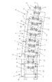
図面は、本発明に係る道床バラスト掻出し用チェーンの一実施例を示し、図中Aは、軌陸兼用の作業車又は列車に搭載した、道床バラストの掻出し装置(図示、省略)の主要部材を構成する、無端状のバラスト掻出し用チェーンで、該チェーンAは、前記掻出し装置の駆動源によって回転する駆動スプロケットと案内スプロケット間に張架され、駆動スプロケットの回転方向に従って移動し、その移動に伴って道床上のバラストや土類の掻出し操作を行う(公知)。 The drawings show one embodiment of a roadbed ballast scraping chain according to the present invention. In the figure, A is a main member of a roadbed ballast scraping device (not shown) mounted on a work vehicle or train that also serves as a railroad. The chain A is an endless ballast scraping chain, and the chain A is stretched between a driving sprocket that is rotated by a driving source of the scraping device and a guide sprocket, and moves according to the rotational direction of the driving sprocket. The ballast and soil are scraped off on the roadbed as it moves (known).
バラスト掻出し用チェーンAは、又、多数の内リンクプレート1,…と外リンクプレート2,…を互いに隔置きにして配し、隣接する内外のリンクプレート1,2を互いに連結して構成する。
The ballast scraping chain A is constituted by arranging a large number of
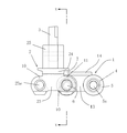
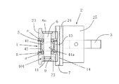
内リンクプレート1は、長手方向の両端部を円筒状にして嵌合透孔13aを設けた内プレート13の長手方向に沿う一側にカバープレート14を設けて構成し、外リンクプレート2は、長手方向に沿う両端部を円筒状にして連結孔23aを設けた一対の外プレート23,23をカバープレート24の、一方の片面24´に前記内プレート13の係合間隙22を存して突設し、カバープレート24の他方の片面24´´には押出しプレート25を突設し、該プレート25にビット3を着脱自在に取付けて構成したものである。
The
そして、嵌合透孔13aに球面軸受4(インナーレース41とアウターレース42とで成る)を嵌合した内リンクプレート1の内プレート13の一端部を、該一端部の嵌合透孔13aの開口端を塞ぐようにしてダストカバー5を重ね合わせた状態で、外リンクプレート2の前記係合間隙22の一端部に係合してダストカバー5の透孔5a、前記外プレート23の連結孔23a及び球面軸受4のインナーレース41の嵌合孔41aを一致させ、これらに一方の外プレート23側の連結孔23a側からジョイントピン6を嵌挿させて、頭部6aを一方の外プレート23に係止させ、先端部を他方の外プレート23に係止手段101によって係止させることによって一対の内、外のリンクプレート1,2は互いに連結され、以下、内リンクプレート1に対しては外リンクプレート2、外リンクプレート2に対しては内リンクプレート1をそれぞれ配して交互に前記方法で連結することにより実施例のバラスト掻出し用チェーンAを得ることができる。
Then, one end portion of the
前記ダストカバー5は、ゴムや樹脂の弾性体で構成し、前記透孔5aを構成する、ほぼ円筒状にして厚肉とした主体部51の周側に、断面ひれ状にして突出する薄肉の周側部52を設けたものである。このダストカバー5は、前記の通り、透孔5aに前記ジョイントピン6を嵌挿させて、内プレート13(内側リンクプレート1)と外プレート23(外側リンクレート2)との間に、これらプレート13,23が主体部51に密接するようにして介在されて配され、薄肉の周側部52が内プレート13に接して重なり合って、球面軸受4を内嵌した、内プレート1の前記嵌合透孔13aを、この周側部52と前記外プレート23の間には隙間aが形成されるように(すなわち、周側部52は主体部51の軸線方向の一側である前記内プレート13側に偏するように配置されて)閉塞してある。
The
また、内外リンクプレート1,2のカバープレート14,24は、バラスト等の、該内外リンクプレート1,2のプレート13,23に対する衝接を防ぐためで、外リンクプレート2のカバープレート24の両側にジョイントピン6の軸線に沿わせて設けた切欠7に、内リンクプレート2のカバープレート14の端部が係合し、両プレート14,24の連結部に対するバラスト等の接触を防ぐようにしてある。
The
前記押出しプレート25は、バラストや土類を押圧して移動させる機能を成し、この押出しプレート25に突設した前記ビット3(押出しプレート25に着脱自在に、すなわち交換自在に組付けてある)は、バラストに衝接してこれを破砕し、かつ、移動させる機能を備えている。
The
前記係止手段101は、ジョイントピン6の先端側に設けた周溝9と外プレート23に設けた通し孔10を一致させ、通し孔10を通じて係止ピン11の一半を周溝9に係合させて該ピン6が外プレート23より抜けない構造になっている。
The locking means 101 matches the
そして、駆動源を動作させて駆動スプロケットを回転させると、該スプロケットが噛み合うバラスト掻出し用チェーンAは、該スプロケットの回転方向に従って移動し、この移動に伴ってチェーンA外部側に突出させたビット3はバラストや土類を砕き、あるいは、これらを押圧して移動させ、所謂掻出し操作が行われる。 When the drive sprocket is rotated by operating the drive source, the ballast scraping chain A with which the sprocket meshes moves according to the rotation direction of the sprocket, and the bit protruded to the outside of the chain A along with this movement. 3 breaks ballast or earth, or presses and moves them, so-called scraping operation is performed.
この掻出し操作時に、バラストや土類の存在によってその移動(ビット延いては駒であるリンクプレートの移動)に支障が生じても、球面軸受の存在によって、移動方向を、左右、上下、斜めにと、自動的に変えて掻出し操作が継続的に行われるのである。 During this scraping operation, even if the movement (the movement of the link plate, which is a piece) is hindered due to the presence of ballast or earth, the moving direction can be changed to the left, right, up, down, and diagonal directions due to the presence of the spherical bearing. On the other hand, the scraping operation is continuously performed by changing automatically.
1 内リンクプレート
2 外リンクプレート
3 ビット
5 ダストカバー
6 ジョイントピン
13 内プレート
13a 嵌合透孔
23 外プレート
1
Claims (2)
Priority Applications (1)
| Application Number | Priority Date | Filing Date | Title |
|---|---|---|---|
| JP2010292356A JP5576263B2 (en) | 2010-12-28 | 2010-12-28 | Roadbed ballast scraping chain |
Applications Claiming Priority (1)
| Application Number | Priority Date | Filing Date | Title |
|---|---|---|---|
| JP2010292356A JP5576263B2 (en) | 2010-12-28 | 2010-12-28 | Roadbed ballast scraping chain |
Publications (2)
| Publication Number | Publication Date |
|---|---|
| JP2012140761A true JP2012140761A (en) | 2012-07-26 |
| JP5576263B2 JP5576263B2 (en) | 2014-08-20 |
Family
ID=46677293
Family Applications (1)
| Application Number | Title | Priority Date | Filing Date |
|---|---|---|---|
| JP2010292356A Active JP5576263B2 (en) | 2010-12-28 | 2010-12-28 | Roadbed ballast scraping chain |
Country Status (1)
| Country | Link |
|---|---|
| JP (1) | JP5576263B2 (en) |
Cited By (2)
| Publication number | Priority date | Publication date | Assignee | Title |
|---|---|---|---|---|
| CN110494374A (en) * | 2017-03-06 | 2019-11-22 | 久益环球地下采矿有限责任公司 | Chain-linked conveyer with cast part |
| CN110725167A (en) * | 2019-11-19 | 2020-01-24 | 常州市瑞泰工程机械有限公司 | Digging Chain Units, Digging Chains and Slope Cleaners |
Families Citing this family (3)
| Publication number | Priority date | Publication date | Assignee | Title |
|---|---|---|---|---|
| US9415939B2 (en) | 2008-04-03 | 2016-08-16 | Joy Mm Delaware, Inc. | Chain and flight conveyor |
| WO2016126717A1 (en) * | 2015-02-03 | 2016-08-11 | Joy Mm Delaware, Inc. | Chain and flight conveyor |
| CA3146838A1 (en) | 2021-01-28 | 2022-07-28 | Joy Global Underground Mining Llc | Chain conveyor and link for same |
Citations (5)
| Publication number | Priority date | Publication date | Assignee | Title |
|---|---|---|---|---|
| JPS62202561U (en) * | 1986-02-04 | 1987-12-24 | ||
| JPH0518411A (en) * | 1991-07-11 | 1993-01-26 | Somitsuku Ishikawa:Kk | Spherical surface slide bearing |
| JPH0564546U (en) * | 1992-02-07 | 1993-08-27 | 東洋ゴム工業株式会社 | Sliding bush |
| JPH0941305A (en) * | 1995-07-26 | 1997-02-10 | Mitsubishi Heavy Ind Ltd | Working vehicle of ballast for railroad |
| JP2002286043A (en) * | 2001-03-26 | 2002-10-03 | Kayaba Ind Co Ltd | Spherical bearing structure |
-
2010
- 2010-12-28 JP JP2010292356A patent/JP5576263B2/en active Active
Patent Citations (5)
| Publication number | Priority date | Publication date | Assignee | Title |
|---|---|---|---|---|
| JPS62202561U (en) * | 1986-02-04 | 1987-12-24 | ||
| JPH0518411A (en) * | 1991-07-11 | 1993-01-26 | Somitsuku Ishikawa:Kk | Spherical surface slide bearing |
| JPH0564546U (en) * | 1992-02-07 | 1993-08-27 | 東洋ゴム工業株式会社 | Sliding bush |
| JPH0941305A (en) * | 1995-07-26 | 1997-02-10 | Mitsubishi Heavy Ind Ltd | Working vehicle of ballast for railroad |
| JP2002286043A (en) * | 2001-03-26 | 2002-10-03 | Kayaba Ind Co Ltd | Spherical bearing structure |
Cited By (3)
| Publication number | Priority date | Publication date | Assignee | Title |
|---|---|---|---|---|
| CN110494374A (en) * | 2017-03-06 | 2019-11-22 | 久益环球地下采矿有限责任公司 | Chain-linked conveyer with cast part |
| CN110494374B (en) * | 2017-03-06 | 2022-02-25 | 久益环球地下采矿有限责任公司 | Chain conveyor with casting sections |
| CN110725167A (en) * | 2019-11-19 | 2020-01-24 | 常州市瑞泰工程机械有限公司 | Digging Chain Units, Digging Chains and Slope Cleaners |
Also Published As
| Publication number | Publication date |
|---|---|
| JP5576263B2 (en) | 2014-08-20 |
Similar Documents
| Publication | Publication Date | Title |
|---|---|---|
| JP5576263B2 (en) | Roadbed ballast scraping chain | |
| CN109131610B (en) | Wheel track deformation mechanism, running gear and vehicle | |
| JPS5923657Y2 (en) | One-piece track pin | |
| JP3269868B2 (en) | Track chain joint holding method and device | |
| ES2761864T3 (en) | Track link structure and pin joint unit | |
| CN205345102U (en) | A track system that is used for idler yoke piece subassembly and crawler frame of track system | |
| CN100469644C (en) | Link structure for crawler belt and chain for crawler belt formed by connecting the link structure | |
| DE60307487D1 (en) | Modular structure for energy absorption during head impact on vehicle interior parts | |
| CN102145708A (en) | Rack bar supporting device of steering apparatus for vehicle | |
| JP2012255277A (en) | Scraper device of rolling machine | |
| TW201718300A (en) | Railroad vehicle steering bogie | |
| DE102010014811B4 (en) | Buckling / pendulum steering | |
| ITTO20010825A1 (en) | GUIDE ARRANGEMENT FOR A TRACK TYPE WORKING MACHINE. | |
| JP5868235B2 (en) | Emergency rolling method and apparatus for iron wheel in road-rail work vehicle | |
| CN111469874B (en) | An inter-vehicle articulation device for passing a small curve | |
| JP2007083764A (en) | Crawler type traveling body | |
| JP5006874B2 (en) | Anti-slip device | |
| JP2022100180A (en) | Travel assist tool | |
| US1656610A (en) | Chain link hinge | |
| JP2009241885A (en) | Non-pneumatic tire | |
| CN211223661U (en) | Linking mechanism for the joints of chain rails, chain rails and paver | |
| JP2012001011A (en) | Lower traveling body of crawler vehicle | |
| US1154143A (en) | Axle-mount. | |
| CN221418443U (en) | A tensioning mechanism for a chain track | |
| JP2007091101A (en) | Drive device for crawler traveling device |
Legal Events
| Date | Code | Title | Description |
|---|---|---|---|
| A621 | Written request for application examination |
Free format text: JAPANESE INTERMEDIATE CODE: A621 Effective date: 20121207 |
|
| A977 | Report on retrieval |
Free format text: JAPANESE INTERMEDIATE CODE: A971007 Effective date: 20130830 |
|
| A977 | Report on retrieval |
Free format text: JAPANESE INTERMEDIATE CODE: A971007 Effective date: 20131018 |
|
| A131 | Notification of reasons for refusal |
Free format text: JAPANESE INTERMEDIATE CODE: A131 Effective date: 20131022 |
|
| A977 | Report on retrieval |
Free format text: JAPANESE INTERMEDIATE CODE: A971007 Effective date: 20131021 |
|
| TRDD | Decision of grant or rejection written | ||
| A01 | Written decision to grant a patent or to grant a registration (utility model) |
Free format text: JAPANESE INTERMEDIATE CODE: A01 Effective date: 20140610 |
|
| A61 | First payment of annual fees (during grant procedure) |
Free format text: JAPANESE INTERMEDIATE CODE: A61 Effective date: 20140703 |
|
| R150 | Certificate of patent or registration of utility model |
Ref document number: 5576263 Country of ref document: JP Free format text: JAPANESE INTERMEDIATE CODE: R150 |
|
| R250 | Receipt of annual fees |
Free format text: JAPANESE INTERMEDIATE CODE: R250 |
|
| R250 | Receipt of annual fees |
Free format text: JAPANESE INTERMEDIATE CODE: R250 |
|
| R250 | Receipt of annual fees |
Free format text: JAPANESE INTERMEDIATE CODE: R250 |
|
| R250 | Receipt of annual fees |
Free format text: JAPANESE INTERMEDIATE CODE: R250 |
|
| R250 | Receipt of annual fees |
Free format text: JAPANESE INTERMEDIATE CODE: R250 |
|
| R250 | Receipt of annual fees |
Free format text: JAPANESE INTERMEDIATE CODE: R250 |
|
| R250 | Receipt of annual fees |
Free format text: JAPANESE INTERMEDIATE CODE: R250 |
|
| R250 | Receipt of annual fees |
Free format text: JAPANESE INTERMEDIATE CODE: R250 |
|
| R250 | Receipt of annual fees |
Free format text: JAPANESE INTERMEDIATE CODE: R250 |