JP2012140821A - Double pipe drilling device - Google Patents
Double pipe drilling device Download PDFInfo
- Publication number
- JP2012140821A JP2012140821A JP2011000524A JP2011000524A JP2012140821A JP 2012140821 A JP2012140821 A JP 2012140821A JP 2011000524 A JP2011000524 A JP 2011000524A JP 2011000524 A JP2011000524 A JP 2011000524A JP 2012140821 A JP2012140821 A JP 2012140821A
- Authority
- JP
- Japan
- Prior art keywords
- casing
- bit
- ring bit
- rotation transmission
- ground
- Prior art date
- Legal status (The legal status is an assumption and is not a legal conclusion. Google has not performed a legal analysis and makes no representation as to the accuracy of the status listed.)
- Granted
Links
- 238000005553 drilling Methods 0.000 title claims abstract description 54
- 230000005540 biological transmission Effects 0.000 claims abstract description 55
- 238000000034 method Methods 0.000 abstract description 21
- 238000009412 basement excavation Methods 0.000 description 49
- 239000011435 rock Substances 0.000 description 10
- 238000010276 construction Methods 0.000 description 3
- 238000011010 flushing procedure Methods 0.000 description 3
- 230000010354 integration Effects 0.000 description 3
- 238000009527 percussion Methods 0.000 description 3
- 230000002093 peripheral effect Effects 0.000 description 3
- 230000000295 complement effect Effects 0.000 description 2
- 238000009933 burial Methods 0.000 description 1
- 238000007796 conventional method Methods 0.000 description 1
- 238000005516 engineering process Methods 0.000 description 1
- 239000012530 fluid Substances 0.000 description 1
- 239000007788 liquid Substances 0.000 description 1
- 239000000463 material Substances 0.000 description 1
- 238000002360 preparation method Methods 0.000 description 1
- 238000010008 shearing Methods 0.000 description 1
- 238000004904 shortening Methods 0.000 description 1
- XLYOFNOQVPJJNP-UHFFFAOYSA-N water Substances O XLYOFNOQVPJJNP-UHFFFAOYSA-N 0.000 description 1
Images




Landscapes
- Earth Drilling (AREA)
Abstract
Description
本発明は、地盤に孔を穿設するために用いられる二重管削孔装置に関する。より詳細には、本発明は、二重管削孔装置を用いて所定深度まで削孔した後、外管を地中に残存させる(埋め殺す)こと無く、地上側に後退させる(引き上げる或いは引き抜く)技術に関する。 The present invention relates to a double pipe drilling device used for drilling holes in the ground. More specifically, in the present invention, after drilling to a predetermined depth using a double-pipe drilling device, the outer pipe is retracted (pulled up or pulled out) to the ground side without remaining (buried) in the ground. ) Technology.
地盤改良工、岩盤グラウチング、グラウンドアンカー工、水抜きボーリング工等の施工時に、地盤に孔を穿設する方法として、ロータリー式ボーリングが一般的である。
ロータリー式ボーリングでは、掘削方向に進む力(給進力)及び回転力が、ボーリングロッド等を介して先端のビットに伝達されて、地盤を掘り進む。
当該給進力及び回転力によって地盤から切り取られた切粉、破砕片、削孔クズ等から成るスライムは、ポンプやエアコンプレッサーから供給される水圧、空気圧等により、ボーリングロッドの内又は外を通過して孔外に排出される。
As a method of drilling holes in the ground during construction such as ground improvement work, rock grouting, ground anchor work, draining boring work, rotary boring is generally used.
In the rotary boring, the force (feeding force) and the rotational force that advance in the excavation direction are transmitted to the bit at the tip via a boring rod or the like to dig the ground.
Slime consisting of chips, crushed pieces, drilled scraps, etc. cut from the ground by the feed force and rotational force passes inside or outside the boring rod by water pressure, air pressure, etc. supplied from a pump or air compressor. Then, it is discharged out of the hole.
ロータリー式ボーリングは比較的簡単な設備で削孔することができるが、対象地盤や現場条件等により(特に削孔時間の短縮等のニーズが存在する場合)、ロータリーパーカッション式ボーリングが広く採用されている。
ロータリーパーカッション式ボーリングは、前記ロータリー式ボーリングに打撃力を付加したもので、ボーリングマシンが打撃力の発生源となるトップハンマー方式である。
ロータリーパーカッション式ボーリングでは、強力な打撃力が付加されるため、礫層や転石層でも急速削孔が可能である。
しかし、トップハンマー方式であるため、ボーリングマシンが設置される地上側で騒音が発生する、という課題が存在する。
また、削孔長が長くなり、ボーリングロッドが長くなると、先端のビットに伝達される打撃力が低下する、という課題も存在する。
Rotary boring can be drilled with relatively simple equipment, but rotary percussion boring is widely adopted depending on the target ground and site conditions (especially when there is a need for shortening drilling time, etc.). Yes.
The rotary percussion type boring is a top hammer type in which a striking force is added to the rotary boring, and a boring machine is a source of the striking force.
With rotary percussion boring, a powerful striking force is added, so rapid drilling is possible even in gravel and boulder layers.
However, because of the top hammer method, there is a problem that noise is generated on the ground side where the boring machine is installed.
Moreover, when the drilling length becomes long and the boring rod becomes long, there is a problem that the striking force transmitted to the bit at the tip is reduced.
上述した課題に対し、ダウンザホールハンマー方式を採用すれば、打撃力発生源が地中の先端ビットの手前に位置するため、地上側における騒音が少なくなる。
また、打撃力発生源が地中の先端ビットの手前に位置するダウンザホールハンマー方式を採用すれば、削孔長が長くなり、ボーリングロッドが長くなっても、先端ビットに伝達される打撃力は低下しない。
When the down-the-hole hammer method is employed for the above-described problems, the impact force generation source is located in front of the tip bit in the ground, so that noise on the ground side is reduced.
In addition, if the down-the-hole hammer method is used in which the source of impact force is located in front of the tip bit in the ground, the drilling length will be longer, and even if the boring rod is longer, the impact force transmitted to the tip bit will be reduced. do not do.
ダウンザホールハンマー方式を採用して地盤を削孔する際に、対象地盤が硬質な岩盤等であり、孔壁が完全に「自立」する場合には、単管削孔方式が可能である。
これに対して、孔壁が崩れるような地盤については、削孔後にアンカー体等を挿入するためにボーリングロッドを後退すると、孔壁が崩れてしまうので、アンカー体等の挿入が困難となる。係る場合(孔壁が崩れるような地盤について、ダウンザホールハンマー方式を採用して削孔する場合)は、二重管削孔方式を採用することになる。
When drilling the ground using the down-the-hole hammer method, if the target ground is a hard rock or the like and the hole wall is completely “self-standing”, a single pipe drilling method is possible.
On the other hand, for the ground where the hole wall collapses, when the boring rod is retracted to insert the anchor body after drilling, the hole wall is collapsed, making it difficult to insert the anchor body or the like. In such a case (when the ground where the hole wall collapses is drilled using the down-the-hole hammer method), the double-pipe drilling method is adopted.
ダウンザホールハンマー方式においては、ボーリングマシンのスイベルに接続されたボーリングロッド(内管)の先端にダウンザホールハンマーを接続し、ダウンザホールハンマーの先端にパイロットビットを接続する。
削孔時には、ボーリングマシンから伝達された給進力及び回転力をパイロットビットに伝達し、また、ダウンザホールハンマーから打撃力をパイロットビットに伝達することにより、地盤或いは岩盤中を掘り進むことができる。
In the down-the-hole hammer method, a down-the-hole hammer is connected to the tip of a boring rod (inner pipe) connected to a swivel of a boring machine, and a pilot bit is connected to the tip of the down-the-hole hammer.
At the time of drilling, the feeding force and the rotational force transmitted from the boring machine are transmitted to the pilot bit, and the striking force is transmitted from the down-the-hole hammer to the pilot bit, so that the ground or rock can be dug.
ダウンザホールハンマーを用いた二重管削孔方式では、ダウンザホールハンマー方式における構成(ボーリングマシン、ボーリングロッド或いは内管、ダウンザホールハンマー、パイロットビット)に加えて、ケーシング(外管)を使用する。
ここで、例えばケーシング(外管)を内管と同じスイベルに接続しても、ケーシング(外管)は給進力及び回転力のみがボーリングマシンから伝達され、内管に接続された打撃源であるダウンザホールハンマーからの打撃力は伝達されていない。そのため、削孔長が長い場合や、対象地盤が硬質な岩盤である場合には、外管の削孔能力が低下してしまい、削孔不能と成ってしまう恐れがある。
そのため、ケーシング(外管)の先端にリングビットを接続し、当該リングビットに内管のパイロットビットを接続することにより、内管先端に接続されたダウンザホールハンマーからの打撃力をケーシング(外管)の先端に伝達することが一般的である。
In the double tube drilling method using the down-the-hole hammer, a casing (outer tube) is used in addition to the configuration in the down-the-hole hammer method (boring machine, boring rod or inner tube, down-the-hole hammer, pilot bit).
Here, for example, even if the casing (outer tube) is connected to the same swivel as the inner tube, the casing (outer tube) is transmitted from the boring machine only with the feeding force and the rotational force, and is an impact source connected to the inner tube. The striking force from a certain down-the-hole hammer is not transmitted. Therefore, when the drilling length is long or when the target ground is a hard rock, the drilling ability of the outer pipe is lowered, and there is a possibility that the drilling is impossible.
Therefore, by connecting a ring bit to the tip of the casing (outer tube) and connecting the pilot bit of the inner tube to the ring bit, the impact force from the down-the-hole hammer connected to the tip of the inner tube is applied to the casing (outer tube). It is common to transmit to the tip of the.
このように、前記ダウンザホールハンマー方式の二重管削孔で地盤を掘進する際には、パイロットビットに供給された給進力、回転力及び打撃力を主な掘進源としている。
そして、パイロットビットにリングビットを接続し、リングビットをケーシング(外管)に接続することにより、パイロットビットによりケーシング(外管)を連行すると共に、パイロットビットを介して、リングビット及びケーシング(外管)に打撃力を伝達している。
Thus, when the ground is dug with the down-the-hole hammer double pipe drilling hole, the feed force, the rotational force and the striking force supplied to the pilot bit are the main excavation sources.
Then, by connecting the ring bit to the pilot bit and connecting the ring bit to the casing (outer pipe), the pilot bit entrains the casing (outer pipe) and, via the pilot bit, the ring bit and the casing (outer pipe). The striking force is transmitted to the tube.
ここで、上記のように地中側でリングビットを介して接続された外管であるケーシングを、さらに地上側のスイベルに接続させると、ケーシングが地上側である後方で拘束されることになり、ケーシングに接続されているリングビットは、(掘削方向或いはその逆方向について)自由に移動することができなくなる。そのため、前記パイロットビットから伝達された打撃力によってリングビットが前方(掘削方向)へ移動しようとしても、ケーシングがスイベルに接続されているため、その様なリングビットの前方(掘削方向)への移動も制限される。
また、リングビットに接続されたパイロットビット自体の移動も制限されてしまうので、円滑な削孔が不可能になってしまう。
さらに、(前方或いは掘削方向への)移動を制限されたリングビットを、無理に(前方或いは掘削方向へ)移動させようとして破損しまう恐れも存在する。
Here, if the casing, which is the outer pipe connected through the ring bit on the ground side as described above, is further connected to the swivel on the ground side, the casing is restrained on the rear side on the ground side. The ring bit connected to the casing cannot move freely (in the excavation direction or vice versa). Therefore, even if the ring bit tries to move forward (excavation direction) by the striking force transmitted from the pilot bit, since the casing is connected to the swivel, such ring bit moves forward (excavation direction). Is also limited.
In addition, since movement of the pilot bit itself connected to the ring bit is also restricted, smooth drilling becomes impossible.
Furthermore, there is a possibility that the ring bit whose movement is restricted (forward or in the excavation direction) may be damaged if it is forced to move (forward or in the excavation direction).
そのため、上述したダウンザホールハンマーを用いた二重管削孔方式によって地盤を掘進する際には、外管(ケーシング)はスイベルに接続せず、内管によって外管(ケーシング)が連行される方式が採用される。
係る方式において、内管と外管を直接的に接続する方法では、内管に伝達された回転力が外管(ケーシング)へ常に伝達されるので、外管(ケーシング)と地山(孔壁)との摩擦により回転力が損失し或いは低下し、削孔精度も低下してしまう。そのため、内管と外管(ケーシング)との間にシューを介装して、内管に伝達された回転力がケーシングに伝達されない構造を採用している。
Therefore, when excavating the ground by the double pipe drilling method using the down-the-hole hammer described above, the outer pipe (casing) is not connected to the swivel, and the outer pipe (casing) is entrained by the inner pipe. Adopted.
In such a method, in the method of directly connecting the inner tube and the outer tube, the rotational force transmitted to the inner tube is always transmitted to the outer tube (casing), so the outer tube (casing) and the ground (hole wall) ), The rotational force is lost or reduced, and the drilling accuracy is also reduced. Therefore, a structure is adopted in which a shoe is interposed between the inner tube and the outer tube (casing) so that the rotational force transmitted to the inner tube is not transmitted to the casing.
ここで、地盤を削孔する際に、地盤から切り取られた切粉、破砕片、削孔クズ等から成るスライムが、ケーシングと孔壁の隙間に詰まってしまい、ケーシングがそれ以上動かなくなる現象、いわゆる「ジャミング」が生じる場合がある。
その様なジャミングを防止するためには、削孔途中で流体を噴射して(フラッシング)削孔内のスライムを除去し、それと共に、外管(ケーシング)を回転させることにより、ケーシング(外管)と孔壁が一体化することを防止する(いわゆる「縁を切る」)ことが、一般的に行われている。
Here, when drilling the ground, the slime consisting of chips, crushed pieces, drilled scraps, etc. cut from the ground is clogged in the gap between the casing and the hole wall, the phenomenon that the casing does not move any more, So-called “jamming” may occur.
In order to prevent such jamming, fluid is ejected in the middle of drilling (flushing) to remove slime in the drilling hole, and at the same time, by rotating the outer tube (casing), the casing (outer tube) ) And the hole wall are generally prevented from being integrated (so-called “cutting edges”).
ところで、上述した様な掘削方式、すなわち、ダウンザホールハンマー方式の二重管削孔により削孔を行った場合には、内管と外管(ケーシング)との間にシューを介装してケーシングに回転力が伝達されない構造であるため、ジャミング解消のために外管を回転させることができない。
そのため、従来技術におけるダウンザホールハンマー方式の二重管削孔では、削孔用のボーリングマシンとは別のボーリングマシンを用意して外管(ケーシング)と接続して、当該別のボーリングマシンにより外管(ケーシング)を回転させることにより、ケーシング(外管)と孔壁が一体化することを防止していた。
或いは、ケーシング(外管)と孔壁が一体化することを積極的に防止せずに、外管(ケーシング)を地上側に後退させることなく、地盤或いは岩盤中に残置していた(埋め殺していた)。
By the way, when drilling is performed by the above-described excavation method, that is, the down-the-hole hammer type double tube drilling, a shoe is interposed between the inner tube and the outer tube (casing) to the casing. Since the rotational force is not transmitted, the outer tube cannot be rotated to eliminate jamming.
For this reason, in the down-the-hole hammer type double pipe drilling in the prior art, a boring machine different from the boring machine for drilling is prepared and connected to the outer pipe (casing), and the outer pipe is connected by the other boring machine. By rotating the (casing), the casing (outer tube) and the hole wall are prevented from being integrated.
Or, without actively preventing the casing (outer pipe) and the hole wall from being integrated, the outer pipe (casing) was left behind in the ground or rock without retreating to the ground side (burial) )
しかし、(削孔用のボーリングマシンとは)別のボーリングマシンを用意することは、工事の費用、設備が増大してしまう事態を招いてしまう。また、当該別のボーリングマシンと外管(ケーシング)を接続する作業も、特殊な方法を採用して実施しなければならない。
一方、外管(ケーシング)を地盤或いは岩盤中に残置させることは、少なくとも埋め殺される外管(ケーシング)の分だけ費用が増大する。
さらに、外管(ケーシング)を地盤或いは岩盤中に残置することができない場合も存在する。
However, the preparation of another boring machine (in contrast to the boring machine for drilling) leads to a situation where construction costs and facilities increase. Moreover, the operation | work which connects the said another boring machine and an outer tube | pipe (casing) must also be implemented by employ | adopting a special method.
On the other hand, if the outer pipe (casing) is left in the ground or rock, the cost increases at least by the amount of the outer pipe (casing) to be buried.
Furthermore, there are cases where the outer pipe (casing) cannot be left in the ground or rock.
その他の従来技術として、例えば、掘削後に地中に埋め殺すリングビットの掘削刃の数を最小限に抑えることが出来る二重管掘削方式で用いられる二重管掘削ビットが提案されている(特許文献1参照)。
しかし、係る従来技術は、リングビットの掘削刃の数を減少することを目的とするものであり、上述した従来技術の各種問題点を解消するものではない。
As another conventional technique, for example, a double-pipe drilling bit used in a double-pipe drilling method that can minimize the number of ring bit drilling blades buried in the ground after excavation has been proposed (patented) Reference 1).
However, the related art is intended to reduce the number of ring bit excavating blades, and does not solve the various problems of the prior art described above.
本発明は上述した従来技術の問題点に鑑みて提案されたものであり、ダウンザホールハンマーを用いた二重管削孔方式で用いられる二重管掘削ビットであって、外管を地中に残置させる必要がなく、削孔用ではないボーリングマシンを別途設ける必要もない二重管掘削ビットと、そのケーシングを回転させながら地上側に後退させる工法の提供を目的としている。 The present invention has been proposed in view of the above-mentioned problems of the prior art, and is a double pipe drilling bit used in a double pipe drilling system using a down-the-hole hammer, and an outer pipe is left in the ground. The purpose of the present invention is to provide a double-pipe excavation bit that does not need to be provided and a boring machine that is not for drilling, and a method of retreating the casing to the ground side while rotating the casing.
本発明の二重管削孔装置は、スイベルジョイント(12)を介して地上側のボーリングマシン(図示せず)に接続された内管(ボーリングロッド10)と、内管(10)の地中側先端に接続されたダウンザホールハンマー(14)と、ダウンザホールハンマー(14)に接続されたパイロットビット(16:内管の一部を構成)と、パイロットビット(16)の半径方向外側に配置され且つパイロットビット(16)から(凸部16Tと、凸部16Tと相補的な形状の溝20Rの係合により)回転力(R)及び給進力(BF:掘削方向に進む力)が伝達可能な円環状のリングビット(20)と、リングビット(20)の地上側に接続され且つリングビット(20)から(突起20Tと溝22Rとの係合により)給進力(BF)が伝達可能な円環状のケーシングシュー(22)と、地中側の先端がケーシングシュー(22)に固着(例えば、溶接)された外管(ケーシング24)を有し、リングビット(20)には回転伝達用突起(N1)が形成されており、ケーシングシュー(22)には回転伝達用突起(N1)が進入可能な切欠部(N2)が形成されており、リングビット(20)における回転伝達用突起(N1)は、後退時に切欠部(N2)内に進入し、回転伝達用突起(N1)が切欠部(N2)内の側縁(N2S)と当接して、リングビット(20)の回転をケーシングシュー(22)及び外管(ケーシング24)に伝達する機能を有していることを特徴としている。
The double-pipe drilling device of the present invention includes an inner pipe (boring rod 10) connected to a ground-side boring machine (not shown) via a swivel joint (12), and an underground pipe of the inner pipe (10). A down-the-hole hammer (14) connected to the side tip, a pilot bit (16: constituting a part of the inner pipe) connected to the down-the-hole hammer (14), and disposed radially outside the pilot bit (16); Rotational force (R) and feed force (BF: force that advances in the excavation direction) can be transmitted from the pilot bit (16) (by engaging the
上述する構成を具備する本発明の二重管掘削装置によれば、後退時においては、リングビット(20)における回転伝達用突起(N1)が、ケーシングシュー(22)に形成された切欠部(N2)内に進入し、リングビット(20)が回転すると、回転伝達用突起(N1)が切欠部(N2)内の側縁(N2S)と当接して、リングビット(20)の回転がケーシングシュー(22)及び外管(ケーシング24)に伝達される。
そのため、スライムが外管(24)と掘削孔の内壁との間に詰まり、いわゆる「ジャミング」を生じて、外管(24)が後退方向に動かなくなってしまっても、回転伝達用突起(N1)、切欠部(N2)、ケーシングシュー(22)を介して、リングビット(20)から外管(24)に回転が伝達する。
そして外管(24)を回転すると、いわゆる「縁を切る」ことが行われて、外管(24)の外周面とその周辺のスライムは剪断され、外管(24)と図示しない掘削孔内壁との一体化が解除される。そして、外管(24)は、後退方向に移動可能となり、地上側に後退することが可能になる。
According to the double-pipe excavation device of the present invention having the above-described configuration, the rotation transmission projection (N1) in the ring bit (20) is formed in the notch portion formed in the casing shoe (22) when retreating. When the ring bit (20) rotates into the N2), the rotation transmission projection (N1) comes into contact with the side edge (N2S) in the notch (N2), and the rotation of the ring bit (20) is the casing. It is transmitted to the shoe (22) and the outer tube (casing 24).
Therefore, even if the slime is clogged between the outer tube (24) and the inner wall of the excavation hole, so-called "jamming" occurs, and the outer tube (24) does not move in the backward direction, the rotation transmission projection (N1) ), The rotation is transmitted from the ring bit (20) to the outer tube (24) through the notch (N2) and the casing shoe (22).
Then, when the outer pipe (24) is rotated, so-called “cutting the edge” is performed, and the outer peripheral surface of the outer pipe (24) and the surrounding slime are sheared, and the outer pipe (24) and the inner wall of the unillustrated drilling hole Integration with is released. The outer pipe (24) can be moved in the backward direction, and can be moved back to the ground side.
この様に本発明によれば、外管を後退するに際して、削孔用のボーリングマシンとは別のボーリングマシンを用意しなくても、外管(24)を確実に地上側に後退させることが出来る。そのため、工事の費用、設備の増大を防止することが出来る。そして、削孔用のボーリングマシンとは別のボーリングマシンと外管を接続する特殊な作業も、不要となる。
そして、本発明によれば、後退時に外管を地盤或いは岩盤中に残置させる必要がないので、少なくとも埋め殺される外管(ケーシング)の分だけ費用を節約することが出来る。そして、外管(24)を地盤或いは岩盤中に残置することができない施行条件の現場であっても、施行することが出来る。
Thus, according to the present invention, when the outer pipe is retracted, the outer pipe (24) can be reliably retracted to the ground side without preparing a boring machine separate from the boring machine for drilling. I can do it. Therefore, it is possible to prevent an increase in construction costs and facilities. Further, a special work for connecting the outer pipe with a boring machine different from the boring machine for drilling is also unnecessary.
According to the present invention, since it is not necessary to leave the outer pipe in the ground or the rock when retreating, it is possible to save the cost by at least the outer pipe (casing) to be buried. And even if it is the site of the enforcement conditions which cannot leave an outer pipe | tube (24) in the ground or a bedrock, it can enforce.
さらに本発明によれば、掘削時には、従来技術におけるダウンザホールハンマー方式の二重管削孔により削孔を行った場合と同様に、パイロットビット(16)及びリングビット(20)により、地盤及び岩盤を掘削しつつ、外管(24)を掘削方向に移動することが出来る。 Further, according to the present invention, during excavation, the ground and the rock are removed by the pilot bit (16) and the ring bit (20) in the same manner as when drilling with the down-the-hole hammer type double pipe drilling in the prior art. The outer pipe (24) can be moved in the excavation direction while excavating.
以下、添付図面を参照して、本発明の実施形態について説明する。
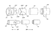
最初に図1、図2を参照して、図示の実施形態が適用されるダウンザホールハンマーを用いた二重管削孔方式の一例を図解する。
図1において、ボーリングロッド10(内管)には、図1の右側でスイベルジョイント12に接続しており、スイベルジョイント12は図示しないボーリングマシンに接続されている。
一方、ボーリングロッド10の地中側(図1では左側)の先端には、ダウンザホールハンマー14が接続されており、ダウンザホールハンマー14はパイロットビット16(内管)と接続している。パイロットビット16の地中側先端(図1では左端)には掘削用チップ18が設けられている。
Embodiments of the present invention will be described below with reference to the accompanying drawings.
First, referring to FIG. 1 and FIG. 2, an example of a double pipe drilling method using a down-the-hole hammer to which the illustrated embodiment is applied is illustrated.
In FIG. 1, a boring rod 10 (inner pipe) is connected to a swivel joint 12 on the right side of FIG. 1, and the swivel joint 12 is connected to a boring machine (not shown).
On the other hand, a down-the-
パイロットビット16の半径方向外側には、円環状のリングビット20が設けられている。リングビット20の地中側先端(図1、図2の左端)には、掘削用チップ21が設けられている。
図2で示すように、パイロットビット16の地上側端部(図2では右端)には螺旋の一部分の様な凸部16Tが設けられており、リングビット20の地上側端部(図2では右端)には、パイロットビット16の凸部16Tと相補的な形状の溝20Rが形成されている。そして、パイロットビット16の凸部16Tが、リングビット20の溝20Rに挿入されることにより、パイロットビット16とリングビット20とが接続され、パイロットビット16に作用する回転力、給進力、打撃力は、凸部16T及び溝20Rを介して、パイロットビット20に伝達される。
ところで、パイロットビット16の凸部16Tとリングビット20の溝20Rとの嵌合状態が保持されているときは、パイロットビット16とリングビット20とは一体的に作動するが、嵌合状態が解除される方向の力が加わることにより、パイロットビット16とリングビット20が一体化した状態は解除される。すなわち、図2において、掘削方向(図2の矢印BF方向)に対して左回りの回転力KLが作用すると、パイロットビット16の凸部16Tはリングビット20の溝20Rから解放されて、パイロットビット16とリングビット20との一体的が解除される構造となっている。
An
As shown in FIG. 2, a
By the way, when the fitting state between the
再び図1、図2において、リングビット20の地上側(図1、図2の右端)には、円環状のケーシングシュー22が配置されており、ケーシングシュー22は、地上側端部(図1、図2の右端)の溶接部Wで、ケーシング24(外管)と固着されている。
図1では、複数設けられたケーシング24同士がネジ接続されており、図1で示すように、最も地上側(図1では右側)に配置されているケーシング24の地上側端部(図1の右端)24Eは、スイベルジョイント12とは離隔している。すなわち、ケーシング24は、スイベルジョイント12に対して「フリー」状態となっている。
1 and 2, an
In FIG. 1, a plurality of
図2において、リングビット20の外周面には、円周方向全周に亘って延在する突起20Tが形成されている。そして、ケーシングシュー22の内周面には、円周方向全周に亘って延在する溝22Rが形成されている。
ここで、図6を参照すると、リングビット20の突起20Tが、ケーシングシュー22の溝22Rに嵌合している。そして、リングビッド20が掘削方向(図6の矢印BF方向)に移動するときは、突起20Tの地中側(図6では左側)端部20Tfが、ケーシングシュー22の溝22Rの地中側(図6では左側)端部22Rfに当接して、動力を伝達する。
さらに、回転方向(図6の矢印KR方向及びKL方向)については、詳細を後述する回転伝達用突起N1が切欠部N2に嵌合している場合を除き、リングビット20の回転はケーシングシュー22には伝達されない構造となっている。そして、図6のリングビット20が掘削方向(図6の矢印BF方向)に移動するときは、回転伝達用突起N1とケーシングシュー22の地中側端部(図6の左端)22Eとは、適切な間隔が保たれている。
そのため、リングビット20とケーシングシュー22は掘削方向(図6の矢印BF方向)に対しては一体的に移動するが、リングビット20の回転はケーシングシュー22には伝達されない。
In FIG. 2, a
Here, referring to FIG. 6, the
Further, with respect to the rotation direction (arrow KR direction and KL direction in FIG. 6), the rotation of the
Therefore, the
図1、図2で示す二重管削孔ビットを使用する二重管削孔方式においては、ダウンザホールハンマー14にパイロットビット16が接続され、回転力と給進力、及びダウンザホールハンマー14から伝達される打撃力が、パイロットビット16とリングビット20に伝達されて、地盤(岩盤を含む)が削孔される。
地中側(図1、図2の左側)に掘削しつつ移動する際には、ダウンザホールハンマー14とパイロットビット16が接続され、凸部16T及び溝20Rを介して、パイロットビット16とリングビット20は一体的に移動する。
そして、リングビット20の掘削方向に対する矢印BF及び矢印BR(図1)方向の動きは、リングビット20の突起20Tとケーシングシュー22の溝22によりケーシングシュー22に伝達され、(ケーシングシュー22とケーシング24は溶接部Wで固着されているので、)ケーシング24に伝達される。
これにより、地中側(図1、図2の左側)に掘削しつつ移動する際に、ケーシング24も地中側に連行される。
ここで、リングビット20の突起20Tとケーシングシュー22の溝22Rは、矢印KR及び矢印KL(図1)方向の回転力は伝達しないので、リングビット20の回転はケーシングシュー22には伝達されない。そのため、ケーシング24の摩擦により、パイロットビット16及びリングビット20の回転力が損失することはなく、削孔精度も低下しない。
In the double pipe drilling method using the double pipe drill bit shown in FIGS. 1 and 2, the
When moving while excavating to the underground side (left side in FIGS. 1 and 2), the down-the-
The movement of the
Thereby, when moving while excavating to the underground side (left side of FIGS. 1 and 2), the
Here, the
図2において、リングビット20には回転伝達用突起N1が形成され、ケーシングシュー22の地中側端部(図2では左端)には切欠部N2が形成されている。
回転伝達用突起N1、切欠部N2については、図3〜図9を参照して後述する。
In FIG. 2, the
The rotation transmission protrusion N1 and the notch N2 will be described later with reference to FIGS.
次に、図2〜図7を参照して、図示の実施形態の要部と、掘削時の態様について説明する。
図3は、掘削時(リングビット16が地中側に前進する際)におけるパイロットビット16、リングビット20、ケーシングシュー22、ケーシング24を示している。
掘削時には、前述したように、パイロットビット16の凸部16Tとリングビット20の溝20Rとの接続が解除される方向(図2の矢印KL方向)へ回転させないように、凸部16Tと溝20Rとの接続を保持しながら掘削することにより、パイロットビット16に伝達される給進力(掘削方向BFへ進行しようとする力)、回転力、打撃力等がリングビット20に伝達される。
Next, with reference to FIGS. 2-7, the principal part of embodiment of illustration and the aspect at the time of excavation are demonstrated.
FIG. 3 shows the
At the time of excavation, as described above, the
図3及び図6で示す掘削時には、リングビット20の突起20Tの地中側縁部(前縁)20Tfが、ケーシングシュー22の溝22Rの地中側縁部(前縁)22Rfに当接しており、リングビット20に伝達される給進力を、ケーシングシュー22及びケーシング24に伝達している。
図3及び図6の例では、掘削時において、リングビット20の突起20Tの地上側縁部(後縁)20Trが、ケーシングシュー22の溝22Rの地上側縁部(後縁)22Rrには当接しておらず、例えば、9mmの間隔が設けられている。
上述した様に、リングビット20に回転力が伝達されても、リングビット20の突起20Tがケーシングシュー22の溝22R内を空回りするのみであるため、突起20T及び溝22Rを介して、回転力がケーシングシュー22及びケーシング24に伝達されることはない。
3 and 6, the ground side edge (front edge) 20Tf of the
3 and 6, the ground side edge (rear edge) 20Tr of the
As described above, even if the rotational force is transmitted to the
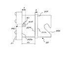
リングビット20先端面には掘削用チップ21が溶接され、さらにその後方の領域(リングビット前縁部)20Fの一部にはピンPN1が埋設されている。そして、リングビット前縁部20Fとケーシングシュー22の地中側端部(前端)22Eとの間の環状の空間(例えば、矢印BR方向の間隔は9mm)には、ピンPN1の地上側部分(図3では右側部分)が、回転伝達用突起N1として(例えば、矢印BR方向に7mmだけ)突出している。
図3及び図6で示す掘削時には、回転伝達用突起N1の地上側端部(先端)N1Eは、ケーシングシュー22の地中側端部(前端)22Eには当接していない。図6で示すように、回転伝達用突起N1の地上側端部(先端)N1Eとケーシングシュー前端22Eの間には、隙間W(図3の例では、矢印BR方向の間隔が2mmの隙間)が存在する。
The
At the time of excavation shown in FIGS. 3 and 6, the ground side end (tip) N1E of the rotation transmission projection N1 is not in contact with the ground side end (front end) 22E of the
図3では明示されていないが、図1、図2、図5〜図9で示す様に、ケーシングシュー22の前端22Eには、切欠部N2が形成されている。
そして、前述した様に掘削時においては、回転伝達用突起N1は切欠部N2内には進入しない。そのため、掘削時において、回転伝達用突起N1と切欠部N2が係合することにより、リングビット20に回転力がケーシングシュー22に伝達されることはない。
Although not explicitly shown in FIG. 3, a notch N <b> 2 is formed at the
As described above, during excavation, the rotation transmission projection N1 does not enter the notch N2. Therefore, during excavation, the rotational force is not transmitted to the
次に、パイロットビット16を地上側(図3の矢印BR方向)へ後退させる際(後退時:引き抜き時)の態様を説明する。
後退時でも、前述したようなパイロットピット16とリングビット20の接続を解放する方向(図2の矢印KL方向)への回転力を生じさせない限り、パイロットビット16とリングビット20とは一体的に作動する。
Next, the mode when the
Even when reversing, the
図6、図7において、リングビット20を地上側(図6、図7の右側)に後退させようとする力BRにより、リングビット20が地上側に移動すると、リングビット20の突起20Tの地上側縁部(後縁)20Trが、ケーシングシュー22の溝22Rの地上側縁部(後縁)22Rrに当接する。その結果、後退させようとする力BRが、ケーシングシュー22及びケーシング24に伝達される。
このとき、回転伝達用突起N1の地上側端部(先端)N1Eがケーシングシュー前端22Eに当接してしまわないように、回転伝達用突起N1を切欠部N2に進入させるべく、リングビット20を回転して位置調整を行なう。
このように、パイロットビット16の後退時にも、突起20Tと溝22Rとが「面で接触」することにより、スムーズな移動を可能とし、回転伝達用突起N1の地上側端部(先端)N1Eがケーシングシュー22の端部に当接することによる「片利き」を防止している。
6 and 7, when the
At this time, the
Thus, even when the
ここで、前述した様に、掘削時の態様では、リングビット20が回転した場合に、リングビット20の突起20Tがケーシングシュー22の溝22R内を空回りするのみであるため、突起20T及び溝22Rを介して、リングビット20の回転がケーシングシュー22に伝達されることはない。
しかし、図7を参照すると、後退時において回転伝達用突起N1を切欠部N2に進入させた状態で、リングビット20に回転力KRを与えた場合には、回転伝達用突起N1の側面N1Sと切欠部N2内の側縁N2Sが当接し、リングビット20の回転は、回転伝達用突起N1及び切欠部N2を介してケーシングシュー22に伝達される。
Here, as described above, in the excavation mode, when the
However, referring to FIG. 7, when the rotational force KR is applied to the
図3において、上記の後退時の態様で、回転力KRを与えた場合には、リングビット20の回転が回転伝達用突起N1及び切欠部N2を介してケーシングシュー22に伝達されるため、当該回転力は溶接部分Wを介してケーシング24に伝達される。
さらに、図6、図7を参照して、任意の距離まで後退させた前記パイロットビット16を、前述した掘削時と同様に前進させる(図6、図7の矢印BF方向に移動させる)と、回転伝達用突起N1は切欠部N2から解放されるため、リングビット20への回転力はケーシングシュー22に伝達されないので、スムーズな掘削が再開可能になる。
In FIG. 3, when the rotational force KR is applied in the above-described backward mode, the rotation of the
Furthermore, referring to FIG. 6 and FIG. 7, when the
このようにして、回転伝達用突起N1、切欠部N2、ケーシングシュー22を介してリングビット20から伝達された回転力により、ケーシング24を回転しながら前後進し、且つ、液体を噴射することにより、「フラッシング」が可能となる。
また、地盤から切り取られた切粉、破砕片、削孔クズ等から成るスライムが、ケーシング24と掘削孔内壁(図示せず)の隙間に詰まってしまい、いわゆる「ジャミング」が生じて、ケーシング24が動かなったとしても、回転伝達用突起N1、切欠部N2、ケーシングシュー22を介して、リングビット20からケーシング24に回転力が伝達されてケーシング24が回転すれば、いわゆる「縁を切る」ことが行われて、ケーシング24と図示しない孔壁の一体化が解除され、ケーシング24を地上側に後退させることが可能になる。
In this manner, the
In addition, slime made of chips, crushed pieces, drilling scraps, and the like cut from the ground is clogged in the gap between the
図1〜図9を参照して説明した掘削及び後退作業を実行するためには、リングビット20の回転伝達用突起N1と、ケーシングシュー22の切欠部N2の各種寸法が、所定の条件を充足する必要がある。
以下、図4〜図9を主として参照しつつ、回転伝達用突起N1と切欠部N2の仕様について述べる。
In order to execute the excavation and retreating operations described with reference to FIGS. 1 to 9, various dimensions of the rotation transmission protrusion N1 of the
Hereinafter, the specifications of the rotation transmission projection N1 and the notch N2 will be described with reference mainly to FIGS.
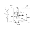
図9を参照して上述した様に、掘削時において、回転伝達用突起N1の先端N1Eと、ケーシングシュー22の前端22Eの間には、隙間W(例えば、2mmの隙間)が存在する。
この隙間Wの寸法が大き過ぎると、リングビット前縁部20Fの地上側端部(図9では右端部)20Feと、ケーシングシュー22の前端22Eとの間における寸法δ(図示の例では、例えば9mm)の環状の空間が大きくなり過ぎてしまい、当該環状空間(幅寸法δ)に異物が進入してしまう恐れがある。
一方、隙間Wの寸法が小さ過ぎると、掘削時において、回転伝達用突起N1の先端N1Eが、ケーシングシュー22の前端22Eと干渉してしまい、先端N1Eが摩耗してしまう。
出願人による研究では、隙間Wは、1mm〜3mmの範囲が適当であることが分っている。
As described above with reference to FIG. 9, during excavation, a gap W (for example, a gap of 2 mm) exists between the tip N1E of the rotation transmission protrusion N1 and the
If the dimension of the gap W is too large, a dimension δ (in the illustrated example, for example, between the ground side end portion (right end portion in FIG. 9) 20Fe of the ring bit
On the other hand, if the size of the gap W is too small, the tip N1E of the rotation transmission projection N1 interferes with the
According to the research by the applicant, the gap W is suitably in the range of 1 mm to 3 mm.
図4において、回転伝達用突起N1の長さ(端部20Feから先端N1Eまでの長さ)を符号aで示し、リングビット前縁部20Fの端部20Feと突起20Tの前縁20Tfの間隔を符号CLで示し、突起20Tの幅寸法(前縁20Tfから後縁20Trまでの距離)を符号bで示す。
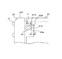
そして、図5において、切欠部N2の深さ(ケーシングシュー22の前端22Eと切欠部N2の底部KAeとの距離)を符号Dで示し、切欠部N2の底部KAeと溝22Rの前縁22Rfの距離を符号L2で示し、溝22Rの幅寸法(前縁22Rfから後縁22Rrまでの距離)を符号H2で示す。
掘削時には、図6で示すように、リングビット20の突起20Tの前縁20Tfが、ケーシングシュー22の溝22Rの前縁22Rfに当接する。そして、上述した様に、回転伝達用突起N1の先端N1Eと、ケーシングシュー22の前端22Eの間には、隙間W(図6)が存在する。
従って、以下の式が成り立つ。
D+H2=CL−a−W・・・(1)
In FIG. 4, the length of the rotation transmitting projection N1 (the length from the end 20Fe to the tip N1E) is indicated by reference symbol a, and the distance between the end 20Fe of the ring bit
In FIG. 5, the depth of the notch N2 (the distance between the
At the time of excavation, as shown in FIG. 6, the front edge 20Tf of the
Therefore, the following equation holds.
D + H2 = CL−a−W (1)
一方、後退時においては、図7で示すように、リングビット20を地上側(図7では右側)に移動することにより、突起20Tの後縁20Trが、ケーシングシュー22の溝22Rの後縁22Rrと当接する。
掘削時には、突起20Tの前縁20Tfがケーシングシュー22の溝22Rの前縁22Rfに当接しているので、掘削時から後退時に移行する際に、突起20Tは、溝22Rの前縁22Rfに当接している位置から、溝22Rの後縁22Rrと当接する位置まで後退する(地上側に移動する)ことになる。その際の突起20Tの移動量mは、 m=H2−b となる。
後退時において、回転伝達用突起N1が切欠部N2内に進入する長さを符号X(図8参照)とすれば、 m=X+W となる。
さらに、後退時の回転伝達用突起N1の先端N1Eと切欠部N2の底部KAeの隙間寸法を符号Y(図8参照)とすれば、 Y=W+D−m となる。
すなわち、突起20Tの移動量mには、次の関係式が成り立つ。
m=H2−b=W+X=W+D−Y・・・(2)
On the other hand, at the time of retraction, as shown in FIG. 7, the
Since the front edge 20Tf of the
If the length at which the rotation transmitting projection N1 enters the notch N2 during the reverse movement is denoted by X (see FIG. 8), m = X + W.
Further, if the clearance dimension between the tip N1E of the rotation transmitting projection N1 and the bottom portion KAe of the notch N2 at the time of reversal is Y (see FIG. 8), Y = W + D−m.
That is, the following relational expression holds for the movement amount m of the
m = H2−b = W + X = W + D−Y (2)
図8で示すように、回転伝達用突起N1の先端N1Eと、切欠部N2の底部(地上側端面)KAe間の隙間における幅寸法Yは、回転伝達用突起N1の先端N1Eが切欠部N2の底部KAeと干渉しない様に設けられた余裕代である。
係る隙間の幅寸法Yが0未満であると、突起20Tの後縁20Trがケーシングシュー22の溝22Rの後縁22Rrと当接する前に、回転伝達用突起N1の先端N1Eが切欠部N2の底部KAeに当接してしまうため、前述した様に「片利き」となり、幅寸法Yが小さ過ぎても、掘削時において、回転伝達用突起N1の先端N1Eと切欠部N2の底部KAeとの隙間に入ったスライム等により干渉してしまう恐れがある。
一方、上式(2)より、前記幅寸法Yは、切欠部N2の深さD及び隙間Wから突起20Tの移動量mを引いた数値となる。突起20Tの移動量mは、突起20Tの幅寸法bと溝22Rの幅寸法H2から一義的に決定されているので、前記幅寸法Yが大き過ぎると、切欠部N2の深さDを大きくしなければならず、切欠部D内に異物が進入してしまう恐れが大きくなってしまう。
出願人による研究では、回転伝達用突起N1の先端N1Eと切欠部N2の底部KAeの隙間寸法Yは、1mm〜3mmの範囲が適当であることが分った。
As shown in FIG. 8, the width dimension Y in the gap between the tip N1E of the rotation transmission projection N1 and the bottom (ground side end surface) KAe of the notch N2 is such that the tip N1E of the rotation transmission projection N1 is the same as the notch N2. It is a margin provided so as not to interfere with the bottom KAe.
When the width dimension Y of the gap is less than 0, before the rear edge 20Tr of the
On the other hand, from the above equation (2), the width dimension Y is a value obtained by subtracting the movement amount m of the
According to the research by the applicant, it has been found that the gap dimension Y between the tip N1E of the rotation transmission projection N1 and the bottom KAe of the notch N2 is suitably in the range of 1 mm to 3 mm.
ここで、前述した「フラッシング」或いは「縁切り」時においては、回転伝達用突起N1が、切欠部N2の側縁N2Sと当接することにより、ケーシング24を回転するための力を伝達するので、後退時に回転伝達用突起N1が切欠部N2内に進入する長さXが小さ過ぎると、剪断力により、回転伝達用突起N1が破損して、リングビット20から脱落してしまう恐れがある。
出願人の研究によれば、後退時に回転伝達用突起N1が切欠部N2内に進入する長さXは、3mm以上であれば、ケーシング24を回転するための力を伝達しても、破損しないことが判明している。
Here, at the time of “flushing” or “edge cutting” described above, the rotation transmitting projection N1 is in contact with the side edge N2S of the cutout portion N2, thereby transmitting a force for rotating the
According to the applicant's research, the length X at which the rotation transmitting projection N1 enters the notch N2 when retreating is 3 mm or more, and even if the force for rotating the
さらに、回転伝達用突起N1を形成するピンPN1の断面積(回転伝達用突起N1の断面積)を符号Aとすれば、 A≧P/(σS) なる式で表現される。ここで、「P」はケーシング24を回転するのに必要な力、「σ」はピンPN1を構成する材料の限界応力、「S」は安全係数である。
ピンPN1の断面は円形であるので、ピンPN1(回転伝達用突起N1)の断面における半径寸法rは、 r≧(P/σSπ)1/2 なる式で表現される。ここで、「π」は円周率である。
Furthermore, if the cross-sectional area of the pin PN1 forming the rotation transmission protrusion N1 (the cross-sectional area of the rotation transmission protrusion N1) is denoted by A, it is expressed by the following formula: A ≧ P / (σS). Here, “P” is a force required to rotate the
Since the cross-section of the pin PN1 is circular, the radial dimension r in the cross-section of the pin PN1 (rotation transmission projection N1) is expressed by the equation r ≧ (P / σSπ) 1/2 . Here, “π” is a circumference ratio.
切欠部N2の円周方向長さN2CLが小さ過ぎると、後退時に回転伝達用突起N1が切欠部N2に進入することが難しくなってしまう。
一方、切欠部N2の円周方向長さN2CLが大き過ぎると、切欠部N2内に異物が進入し易くなってしまう。
出願人の研究では、切欠部N2の円周方向長さN2CLは、ピンPN1或いは回転伝達用突起N1の直径(=2r)の2倍以上で、ケーシングシュー22の円周方向全周寸法の1/4以下が適当である。
If the circumferential length N2CL of the notch N2 is too small, it will be difficult for the rotation transmitting projection N1 to enter the notch N2 when retreating.
On the other hand, if the circumferential length N2CL of the notch portion N2 is too large, foreign matter easily enters the notch portion N2.
According to the applicant's research, the circumferential length N2CL of the notch N2 is not less than twice the diameter (= 2r) of the pin PN1 or the rotation transmission projection N1, and is 1 of the entire circumferential dimension of the
上述した図示の実施形態によれば、掘削時には、パイロットビット16の凸部16Tがリングビット20の溝20Rに当接して、パイロットビット16に伝達される給進力がリングビット20に伝達される。ここで、パイロットビット16の凸部16Tがリングビット20の溝20Rが嵌合しているため、パイロットビット16に伝達される回転力Rも、リングビット20に伝達される。
そして、リングビット20の突起20Tの前縁20Tfがケーシングシュー22の溝22Rの前縁22Rfに当接しているため、リングビット20に伝達される給進力は、ケーシングシュー22及びケーシング24に伝達される。
そのため、パイロットビット16及びリングビット20により、地盤を掘削しつつ、ケーシング24を掘削方向に移動することが出来る。
According to the illustrated embodiment described above, during excavation, the
Since the front edge 20Tf of the
Therefore, the
後退時においては、リングビット20に後退方向BRへの動力が付与されると、リングビット20の突起20Tの後縁20Trがケーシングシュー22の溝22Rの後縁22Rrに当接し、ケーシングシュー22及びケーシング24を地上側に移動することが出来る。そして、リングビット前縁部20Fにおける回転伝達用突起N1が、ケーシングシュー前端22Eの切欠部N2内に進入するので、リングビット20が回転すると、回転伝達用突起N1が切欠部N2内の側縁N2Sと当接して、リングビット20の回転をケーシングシュー22及びケーシング24に伝達する。
そのため、スライムがケーシング24と掘削孔内壁(図示せず)の隙間に詰まってしまい、いわゆる「ジャミング」が生じても、ケーシング24が掘削方向或いは後退方向に動かなくなってしまっても、回転伝達用突起N1、切欠部N2、ケーシングシュー22を介して、リングビット20からケーシング24に回転力を伝達してケーシング24を回転することにより、いわゆる「縁を切る」ことが行われて、ケーシング24と図示しない孔壁の一体化が解除され、ケーシング24を地上側に後退させることが可能になる。
At the time of retreat, when power in the retreat direction BR is applied to the
Therefore, even if the slime is clogged in the gap between the
図示の実施形態はあくまでも例示であり、本発明の技術的範囲を限定する趣旨の記述ではないことを付記する。 It should be noted that the illustrated embodiment is merely an example, and is not a description to limit the technical scope of the present invention.
10・・・ボーリングロッド10
12・・・スイベルジョイント
14・・・ダウンザホールハンマー
16・・・パイロットビット
16T・・・パイロットビットの凸部
18・・・掘削用チップ
20・・・リングビット
20R・・・リングビットの溝
20T・・・リングビットの突起
21・・・掘削用チップ
22・・・ケーシングシュー
22R・・・ケーシングシューの溝
24・・・ケーシング
N1・・・回転伝達用突起
N1E・・・回転伝達用突起先端
PN1・・・ピン
N2・・・切欠部
W・・・回転伝達用突起先端とケーシングシュー前端の隙間
δ・・・リングビット前縁部端部とケーシングシュー前端の間の寸法
a・・・リングビット前縁部端部から突起先端までの長さ
b・・・リングビットの突起の幅寸法
CL・・・リングビット前縁部端部とリングビットの突起前縁の間隔
D・・・切欠部の深さ
L2・・・切欠部底部とケーシングシューの溝前縁までの距離
H2・・・ケーシングシューの溝の幅寸法
m・・・リングビットの突起の移動量
X・・・後退時に回転伝達用突起が切欠部内に進入する長さ
Y・・・回転伝達用突起の先端と切欠部底部の隙間寸法
N2CL・・・切欠部N2の円周方向長さ
10 ... Boring
12 ... Swivel joint 14 ... Down-the-
Claims (1)
Priority Applications (1)
| Application Number | Priority Date | Filing Date | Title |
|---|---|---|---|
| JP2011000524A JP5582649B2 (en) | 2011-01-05 | 2011-01-05 | Double pipe drilling device |
Applications Claiming Priority (1)
| Application Number | Priority Date | Filing Date | Title |
|---|---|---|---|
| JP2011000524A JP5582649B2 (en) | 2011-01-05 | 2011-01-05 | Double pipe drilling device |
Publications (2)
| Publication Number | Publication Date |
|---|---|
| JP2012140821A true JP2012140821A (en) | 2012-07-26 |
| JP5582649B2 JP5582649B2 (en) | 2014-09-03 |
Family
ID=46677350
Family Applications (1)
| Application Number | Title | Priority Date | Filing Date |
|---|---|---|---|
| JP2011000524A Expired - Fee Related JP5582649B2 (en) | 2011-01-05 | 2011-01-05 | Double pipe drilling device |
Country Status (1)
| Country | Link |
|---|---|
| JP (1) | JP5582649B2 (en) |
Cited By (4)
| Publication number | Priority date | Publication date | Assignee | Title |
|---|---|---|---|---|
| JP2017203332A (en) * | 2016-05-13 | 2017-11-16 | 株式会社トライテック | Boring tool and boring method |
| JP2019044513A (en) * | 2017-09-05 | 2019-03-22 | 株式会社ダイカ | Pipe driving method |
| JP2019044564A (en) * | 2017-09-05 | 2019-03-22 | 株式会社ダイカ | Pipe driving method |
| CN112482416A (en) * | 2020-12-24 | 2021-03-12 | 中铁工程装备集团有限公司 | Underground space building water control system and construction method thereof |
Citations (3)
| Publication number | Priority date | Publication date | Assignee | Title |
|---|---|---|---|---|
| JPH11256974A (en) * | 1998-03-09 | 1999-09-21 | Nlc:Kk | Core barrel for extracting rock-core, drill rod and swivel joint |
| JP2000204870A (en) * | 1999-01-19 | 2000-07-25 | Kfc Ltd | Drilling equipment |
| JP2008248505A (en) * | 2007-03-29 | 2008-10-16 | T F T:Kk | Double-pipe excavator and its construction method |
-
2011
- 2011-01-05 JP JP2011000524A patent/JP5582649B2/en not_active Expired - Fee Related
Patent Citations (3)
| Publication number | Priority date | Publication date | Assignee | Title |
|---|---|---|---|---|
| JPH11256974A (en) * | 1998-03-09 | 1999-09-21 | Nlc:Kk | Core barrel for extracting rock-core, drill rod and swivel joint |
| JP2000204870A (en) * | 1999-01-19 | 2000-07-25 | Kfc Ltd | Drilling equipment |
| JP2008248505A (en) * | 2007-03-29 | 2008-10-16 | T F T:Kk | Double-pipe excavator and its construction method |
Cited By (4)
| Publication number | Priority date | Publication date | Assignee | Title |
|---|---|---|---|---|
| JP2017203332A (en) * | 2016-05-13 | 2017-11-16 | 株式会社トライテック | Boring tool and boring method |
| JP2019044513A (en) * | 2017-09-05 | 2019-03-22 | 株式会社ダイカ | Pipe driving method |
| JP2019044564A (en) * | 2017-09-05 | 2019-03-22 | 株式会社ダイカ | Pipe driving method |
| CN112482416A (en) * | 2020-12-24 | 2021-03-12 | 中铁工程装备集团有限公司 | Underground space building water control system and construction method thereof |
Also Published As
| Publication number | Publication date |
|---|---|
| JP5582649B2 (en) | 2014-09-03 |
Similar Documents
| Publication | Publication Date | Title |
|---|---|---|
| JP4270493B2 (en) | Reaming device for ground drilling machine | |
| CN104968882B (en) | digging tool | |
| EP1339939B1 (en) | A drilling tool used in horizontal drilling applications | |
| JP5672435B2 (en) | Double pipe drilling rig | |
| JP5582649B2 (en) | Double pipe drilling device | |
| JP2004293142A (en) | Pipe burial method | |
| JP5783561B2 (en) | Excavation apparatus and excavation method | |
| JP4767307B2 (en) | Double pipe drilling rig | |
| JP5439073B2 (en) | Double pipe drilling tool | |
| JP5574489B2 (en) | Excavator | |
| JP4962129B2 (en) | Drilling tools | |
| JP2000204870A (en) | Drilling equipment | |
| US9290993B2 (en) | Method and system for installation of in-ground conduit | |
| JP4039181B2 (en) | Drilling tools | |
| JP4156582B2 (en) | Underground excavation equipment | |
| JP2004293135A (en) | Ground drilling machine reamer device | |
| JP6153173B2 (en) | Tunnel excavation apparatus and tunnel excavation method | |
| JP4714927B2 (en) | Tunnel excavation method and mirror set bolt | |
| JP2000008758A (en) | Drilling bit | |
| JP4007216B2 (en) | Double pipe drilling tools | |
| JP4504844B2 (en) | Construction method of excavator and underground structure | |
| JP2015166531A (en) | Pit mouth structure of starting pit wall and arrival pit wall in propulsion method | |
| JP3339412B2 (en) | Drilling equipment and drilling method | |
| JP5820573B2 (en) | Drilling tools | |
| JP3246234B2 (en) | Drilling tools |
Legal Events
| Date | Code | Title | Description |
|---|---|---|---|
| A621 | Written request for application examination |
Free format text: JAPANESE INTERMEDIATE CODE: A621 Effective date: 20131111 |
|
| A977 | Report on retrieval |
Free format text: JAPANESE INTERMEDIATE CODE: A971007 Effective date: 20140324 |
|
| A131 | Notification of reasons for refusal |
Free format text: JAPANESE INTERMEDIATE CODE: A131 Effective date: 20140423 |
|
| A521 | Written amendment |
Free format text: JAPANESE INTERMEDIATE CODE: A523 Effective date: 20140520 |
|
| TRDD | Decision of grant or rejection written | ||
| A01 | Written decision to grant a patent or to grant a registration (utility model) |
Free format text: JAPANESE INTERMEDIATE CODE: A01 Effective date: 20140714 |
|
| A61 | First payment of annual fees (during grant procedure) |
Free format text: JAPANESE INTERMEDIATE CODE: A61 Effective date: 20140714 |
|
| R150 | Certificate of patent or registration of utility model |
Ref document number: 5582649 Country of ref document: JP Free format text: JAPANESE INTERMEDIATE CODE: R150 |
|
| S531 | Written request for registration of change of domicile |
Free format text: JAPANESE INTERMEDIATE CODE: R313531 |
|
| R350 | Written notification of registration of transfer |
Free format text: JAPANESE INTERMEDIATE CODE: R350 |
|
| LAPS | Cancellation because of no payment of annual fees |