JP2012141027A - Vibration isolator - Google Patents
Vibration isolator Download PDFInfo
- Publication number
- JP2012141027A JP2012141027A JP2010294889A JP2010294889A JP2012141027A JP 2012141027 A JP2012141027 A JP 2012141027A JP 2010294889 A JP2010294889 A JP 2010294889A JP 2010294889 A JP2010294889 A JP 2010294889A JP 2012141027 A JP2012141027 A JP 2012141027A
- Authority
- JP
- Japan
- Prior art keywords
- vibration isolator
- damper
- fixed plate
- movable plate
- support shaft
- Prior art date
- Legal status (The legal status is an assumption and is not a legal conclusion. Google has not performed a legal analysis and makes no representation as to the accuracy of the status listed.)
- Pending
Links
- 239000000463 material Substances 0.000 claims abstract description 68
- 238000002955 isolation Methods 0.000 claims description 25
- 230000002093 peripheral effect Effects 0.000 claims description 9
- 238000013016 damping Methods 0.000 abstract description 14
- 230000006866 deterioration Effects 0.000 abstract description 5
- 230000005489 elastic deformation Effects 0.000 description 9
- 238000005452 bending Methods 0.000 description 7
- 230000007423 decrease Effects 0.000 description 4
- 229910052751 metal Inorganic materials 0.000 description 4
- 239000002184 metal Substances 0.000 description 4
- 239000002131 composite material Substances 0.000 description 3
- 230000005484 gravity Effects 0.000 description 3
- 230000006835 compression Effects 0.000 description 2
- 238000007906 compression Methods 0.000 description 2
- 238000006073 displacement reaction Methods 0.000 description 2
- 230000000694 effects Effects 0.000 description 2
- 229910052782 aluminium Inorganic materials 0.000 description 1
- XAGFODPZIPBFFR-UHFFFAOYSA-N aluminium Chemical compound [Al] XAGFODPZIPBFFR-UHFFFAOYSA-N 0.000 description 1
- 239000003822 epoxy resin Substances 0.000 description 1
- 238000004519 manufacturing process Methods 0.000 description 1
- 229920000647 polyepoxide Polymers 0.000 description 1
- 230000001902 propagating effect Effects 0.000 description 1
- 125000006850 spacer group Chemical group 0.000 description 1
- 229910001220 stainless steel Inorganic materials 0.000 description 1
- 238000003466 welding Methods 0.000 description 1
- 238000004804 winding Methods 0.000 description 1
Images






Landscapes
- Vibration Prevention Devices (AREA)
Abstract
Description
本発明は、例えば顕微鏡や天秤等の振動の影響を受けやすい種々の精密機器を作業台等に対して弾性的に支持し、作業台等の振動が精密機器に伝播することを抑制するための除振装置に関するものである。 The present invention elastically supports various precision devices, such as a microscope and a balance, which are easily affected by vibrations, with respect to a work table or the like, and suppresses vibrations of the work table or the like from propagating to the precision devices. The present invention relates to a vibration isolator.
従来、このような除振装置としては、例えば特許文献1には、弾性体と粘弾性体を組み合わせた除振装置(防振支持装置)が開示されており、図13に示すように構成されている。
即ち、図13において、除振装置1は、弾性体としてのコイルバネ2と、粘弾性体としてのダンパー材3と、これらのコイルバネ2及びダンパー材3の両端が取り付けられる一対のフランジ4と、から構成されている。Conventionally, as such a vibration isolation device, for example,
That is, in FIG. 13, the
ダンパー材3は、例えばエポキシ樹脂により円柱状に形成されている。
そして、このダンパー材3がコイルバネ2の中空部内に挿入された状態で、ダンパー材3の両端とコイルバネ2の両端がそれぞれ各フランジ4に取り付けられている。
その際、コイルバネ2とダンパー材3の複合体に作用する荷重方向の弾性中心が粘弾性体即ちダンパー材3側に包蔵された状態で、コイルバネ2及びダンパー材3の両端がそれぞれ対応するフランジ4に対してネジ5により固定されている。The
Then, both ends of the
At that time, in a state where the elastic center in the load direction acting on the composite of the
このような構成の除振装置1によれば、一方例えば下方のフランジ5を固定板に取り付けると共に、他方例えば上方のフランジ5を可動板に取り付けて、固定板を作業台等の上面に載置すると共に、可動板上に除振すべき精密機器を搭載する。これにより、固定板に対して水平方向(横方向)と垂直方向(縦方向)に作用する振動に関して、可動板上では大きな減衰を得ることができる。
ここで、除振しようとする精密機器の重量と重心に基づいて、コイルバネ2に作用する荷重を算出して、コイルバネ2の撓み量が基準値となるようにバネ定数を選定している。即ち、当該精密機器専用として、コイルバネ2のバネ定数とダンパー材3の減衰特性を設定している。
これにより、当該精密機器に最適な除振性能を備えた除振装置を製造することが可能となる。According to the
Here, the load acting on the
As a result, it is possible to manufacture a vibration isolator having the optimal vibration isolation performance for the precision instrument.
ところで、上述した除振装置1は、当該精密機器専用としてコイルバネ2のバネ定数及びダンパー材3の減衰特性が設定されているので、種々の精密機器に対して汎用に使用することはできない。
従って、除振装置1を使用して、種々の重量の精密機器の除振を行なう場合には、当該精密機器の重量によって、コイルバネ2の撓み量が一定とならない。By the way, the
Therefore, when the
一般に、除振装置の固有振動数f0は、コイルバネ2のバネ定数をks,ダンパー材3のバネ定数をkd,精密機器の質量をM,除振装置の可動部質量をmとすると、

この式から、除振装置の固有振動数f0は、精密機器の質量Mに依存し、精密機器が重くなると、固有振動数f0が低くなり、また精密機器が軽くなると、固有振動数f0が高くなることが分かる。
同様に、ダンパー材3のバネ定数kdが大きくなると、固有振動数f0は高くなり、バネ定数kdが小さくなると、固有振動数f0は低くなる。In general, the natural frequency f 0 of the vibration isolator is such that the spring constant of the
From this equation, the natural frequency f 0 of the vibration isolator depends on the mass M of the precision device. When the precision device becomes heavy, the natural frequency f 0 decreases, and when the precision device becomes light, the natural frequency f 0. It turns out that 0 becomes high.
Similarly, when the spring constant kd of the
ここで、種々の重量の精密機器を可動板上に搭載する場合、上述した円柱状のダンパー材3においては、ダンパー材3の潰れ量が一定でなくなる。このため、所望の減衰特性が得られなくなってしまうだけでなく、ダンパー材3のバネ特性が大きく変動してしまう。従って、搭載する精密機器の重量が変化するにつれて、除振装置1の固有振動数f0も大きく変化してしまうので、除振性能が劣化してしまう。Here, in the case where precision instruments having various weights are mounted on the movable plate, the amount of crushing of the
本発明は、以上の点に鑑み、簡単な構成により、荷重が変化しても、振動に対する減衰特性及びバネ特性の変化が抑制され、除振性能の劣化が低減されるようにした除振装置を提供することを目的としている。 In view of the above points, the present invention provides a vibration isolator having a simple configuration that suppresses changes in damping characteristics and spring characteristics with respect to vibration and reduces deterioration in vibration isolation performance even when the load changes. The purpose is to provide.
上記目的は、本発明によれば、水平に固定配置された固定板と、前記固定板の上方に配置され、前記固定板との間に介装された少なくとも三本の弾性部材を介して前記固定板に対して相対的に移動可能に支持された可動板と、これらの固定板及び可動板の間で各弾性部材に隣接して配置されたダンパー部と、から構成されていて、前記各ダンパー部が、それぞれ前記固定板または可動板に固定された受け部材と、前記受け部材内で同軸に且つ摺動可能に配置された粘弾性体から成る円板状のダンパー材と、前記ダンパー材の中心付近に一端が連結された支軸と、から構成されており、前記支軸の他端が、前記可動板または固定板に対して揺動手段を介して揺動可能に支持されていることを特徴とする除振装置により、達成される。 According to the present invention, the above object is achieved through the fixing plate horizontally fixed and the at least three elastic members disposed above the fixing plate and interposed between the fixing plate and the fixing plate. Each of the damper parts is composed of a movable plate that is supported so as to be movable relative to the fixed plate, and a damper portion that is disposed adjacent to each elastic member between the fixed plate and the movable plate. Are each a receiving member fixed to the fixed plate or the movable plate, a disk-shaped damper material coaxially and slidably disposed in the receiving member, and a center of the damper material A support shaft having one end connected in the vicinity thereof, and the other end of the support shaft is supported to be swingable with respect to the movable plate or the fixed plate via a swinging means. This is achieved by the featured vibration isolation device.
本発明による除振装置は、好ましくは、前記各ダンパー部における受け部材及び支軸が、無負荷状態で、前記固定板及び可動板に対して垂直に配置されている。 In the vibration isolator according to the present invention, preferably, the receiving member and the support shaft in each damper portion are arranged perpendicular to the fixed plate and the movable plate in a no-load state.
本発明による除振装置は、好ましくは、前記各ダンパー部における受け部材,ダンパー材及び支軸が、無負荷状態で前記固定板及び可動板の一方から他方に向かって中心側に傾斜して配置されている。 In the vibration isolator according to the present invention, preferably, the receiving member, the damper material, and the support shaft in each of the damper portions are disposed so as to be inclined toward the center from one of the fixed plate and the movable plate to the other in an unloaded state. Has been.
本発明による除振装置は、好ましくは、前記受け部材が円筒状の内壁面を有している。 In the vibration isolator according to the present invention, preferably, the receiving member has a cylindrical inner wall surface.
本発明による除振装置は、好ましくは、前記受け部材が開口側から固定側に向かって先細の円錐台状の内壁面を有している。 In the vibration isolator according to the present invention, it is preferable that the receiving member has a tapered truncated cone-shaped inner wall surface from the opening side toward the fixed side.
本発明による除振装置は、好ましくは、前記揺動手段が前記支軸の他端における周面に装着されたコイルバネから構成されている。 In the vibration isolator according to the present invention, preferably, the swinging means is constituted by a coil spring mounted on a peripheral surface at the other end of the support shaft.
本発明による除振装置は、好ましくは、前記揺動手段が前記支軸の他端における周面に装着された円筒状ゴム材から構成されている。 In the vibration isolator according to the present invention, preferably, the swinging means is made of a cylindrical rubber material mounted on a peripheral surface at the other end of the support shaft.
本発明による除振装置は、好ましくは、前記揺動手段が前記支軸に連結された線状バネにより構成されている。 The vibration isolator according to the present invention is preferably constituted by a linear spring in which the swinging means is connected to the support shaft.
本発明による除振装置は、好ましくは、前記揺動手段が、前記可動板または固定板の支持領域の表面にて無負荷状態で当該支軸に対して垂直に設けられたゴム板から構成されている。 The vibration isolator according to the present invention is preferably configured such that the swinging means is a rubber plate provided perpendicular to the support shaft in a no-load state on the surface of the support region of the movable plate or the fixed plate. ing.
上記構成によれば、可動板上に種々の質量の精密機器が搭載されると、弾性部材は、可動板に対して下向きに作用する荷重に応じた撓み量を鉛直方向に生ずる。
ここで、ダンパー部のダンパー材が受け部材内で摺動可能であることから、上述した撓み量の分だけ、ダンパー材が受け部材内でその軸方向に沿って移動する。
従って、弾性部材の撓み量にかかわらず、ダンパー部におけるダンパー材と受け部材の接触状態は一定である。これにより、可動板上に搭載される精密機器の重さによるダンパー材のバネ特性及び減衰特性の変化は極めて小さく、搭載される精密機器の質量が除振装置の除振特性に影響を及ぼすようなことがない。According to the above configuration, when precision devices with various masses are mounted on the movable plate, the elastic member generates a deflection amount in the vertical direction according to a load acting downward on the movable plate.
Here, since the damper material of the damper portion is slidable in the receiving member, the damper material moves along the axial direction in the receiving member by the amount of bending described above.
Therefore, the contact state between the damper member and the receiving member in the damper portion is constant regardless of the amount of bending of the elastic member. As a result, the change in the spring characteristics and damping characteristics of the damper material due to the weight of the precision equipment mounted on the movable plate is extremely small, so that the mass of the precision equipment mounted affects the vibration isolation characteristics of the vibration isolation device. There is nothing.
また、本除振装置の可動板に搭載された精密機器を操作者が操作した場合等において、可動板が固定板に対して相対的に水平方向に変位すると、ダンパー部の支軸が固定板に対して揺動して、ダンパー材が受け部材に対して傾斜する。この際、ダンパー材には大きな変形が生ずることになるので、減衰特性が増大する。これにより、除振装置の可動板そして精密機器の自由振動が迅速に抑制される。
さらに、ダンパー部における水平方向のバネ定数を小さくすることができるため、除振装置の水平方向の固有振動数を低く設定することが可能であり、除振装置の除振性能が向上する。In addition, when an operator operates a precision device mounted on the movable plate of the vibration isolator, the support shaft of the damper portion is fixed when the movable plate is displaced in the horizontal direction relative to the fixed plate. And the damper material is inclined with respect to the receiving member. At this time, since the damper material is greatly deformed, the damping characteristic is increased. Thereby, the free vibration of the movable plate of the vibration isolator and the precision instrument is quickly suppressed.
Furthermore, since the horizontal spring constant in the damper portion can be reduced, the natural frequency in the horizontal direction of the vibration isolation device can be set low, and the vibration isolation performance of the vibration isolation device is improved.
前記受け部材が開口側から固定側に向かって先細の円錐台状の内壁面を有している場合には、可動板に搭載された精密機器の質量が重く、弾性部材の撓み量が大きいと、ダンパー材が受け部材の中空部内により深く押し込まれることにより、ダンパー材の変形量が大きくなり、ダンパー材のバネ特性が強くなる。従って、弾性部材とダンパー材の合成バネ定数が増大することになり、精密機器の質量による影響が相殺され、除振装置の固有振動数の低下が抑制される。 When the receiving member has a tapered truncated cone-shaped inner wall surface from the opening side toward the fixed side, the mass of the precision instrument mounted on the movable plate is heavy, and the amount of bending of the elastic member is large. When the damper material is pushed deeper into the hollow portion of the receiving member, the amount of deformation of the damper material increases and the spring characteristics of the damper material become stronger. Therefore, the combined spring constant of the elastic member and the damper material is increased, the influence of the mass of the precision instrument is offset, and the decrease in the natural frequency of the vibration isolator is suppressed.
また、精密機器の質量が軽く、弾性部材の撓み量が小さいと、ダンパー材が受け部材の中空部内でより開口部に近い位置に位置することにより、ダンパー材の変形量が小さく、あるいはダンパー材が受け部材の内壁面に接触しなくなるので、ダンパー材のバネ定数が弱くなる。従って、弾性部材とダンパー材の合成バネ定数が小さくなり、除振装置の固有振動数の上昇が抑制される。
このようにして、可動板に搭載される精密機器等の質量による除振装置の固有振動数の変化が小さくなるので、除振しようとする精密機器等の重量にかかわらず、十分な除振特性が得られる。Also, if the precision instrument is light and the elastic member has a small amount of deflection, the damper material is located closer to the opening in the hollow portion of the receiving member, so that the amount of deformation of the damper material is small, or the damper material Does not contact the inner wall surface of the receiving member, so that the spring constant of the damper material is weakened. Therefore, the combined spring constant of the elastic member and the damper material is reduced, and an increase in the natural frequency of the vibration isolation device is suppressed.
In this way, since the change in the natural frequency of the vibration isolator due to the mass of the precision instrument mounted on the movable plate is reduced, sufficient vibration isolation characteristics can be obtained regardless of the weight of the precision instrument to be isolated. Is obtained.
このようにして、本発明による除振装置によれば、荷重が変化しても、振動に対する減衰特性及びバネ特性の変化が抑制され、除振性能の劣化が低減され得る。 Thus, according to the vibration isolator according to the present invention, even if the load changes, changes in the damping characteristic and the spring characteristic with respect to vibration can be suppressed, and deterioration of the vibration isolation performance can be reduced.
以下、この発明の好適な実施形態を図1乃至図12を参照しながら、詳細に説明する。
尚、以下に述べる実施形態は、本発明の好適な具体例であるから、技術的に好ましい種々の限定が付されているが、本発明の範囲は、以下の説明において特に本発明を限定する旨の記載がない限り、これらの態様に限られるものではない。Hereinafter, preferred embodiments of the present invention will be described in detail with reference to FIGS. 1 to 12.
The embodiments described below are preferable specific examples of the present invention, and thus various technically preferable limitations are given. However, the scope of the present invention particularly limits the present invention in the following description. As long as there is no description of the effect, it is not restricted to these aspects.
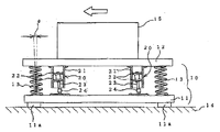
図1及び図2は、本発明による除振装置の第一の実施形態の構成を示している。
図1及び図2において、除振装置10は、固定板11と、可動板12と、これらの固定板11と可動板12との間に配置される弾性部材としての複数個のコイルバネ13及びダンパー部20と、から構成されている。1 and 2 show the configuration of the first embodiment of the vibration isolator according to the present invention.
1 and 2, a
固定板11は、例えば作業台14上に水平に固定配置された例えぱ金属等の板状部材から構成されている。
より詳細には、固定板11は、図示の場合、四隅の底面に設けられたゴム足11aを介して作業台14上に載置されている。The fixed
More specifically, in the illustrated case, the fixing
可動板12は、同様に例えば金属等の板状部材から構成されており、固定板11の上方に所定間隔で水平に配置されている。
さらに、可動板12は、その上面に載置された顕微鏡や天秤等の精密機器15を支持する。
ここで、精密機器15は、その重心が可動板12の水平方向(図2においてX方向及びY方向)の中心を通る垂直軸V上に位置するように、可動板12上に配置される。Similarly, the
Further, the
Here, the
各コイルバネ13は、図2に示すように、それぞれ固定板11及び可動板12の四隅付近において、固定板11及び可動板12に対して垂直に、即ちZ方向に延びるように配置されている。
各コイルバネ13は、それぞれ下端13aが固定板11に対して固定されると共に、上端13bが可動板12に対して固定されている。
ここで、各コイルバネ13は、可動板12上に載置された精密機器15及び可動板12の重量による荷重を受けて、そのバネ定数で決まる撓み量だけ弾性変形している。As shown in FIG. 2, the coil springs 13 are arranged in the vicinity of the four corners of the fixed
Each
Here, each
各ダンパー部20は、それぞれ対応するコイルバネ13に隣接して配置されており、図示の場合、対応するコイルバネ13に対して、X方向に関して中心寄り、即ち垂直軸V寄りに配置されている。 Each
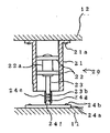
各ダンパー部20は、図3に詳細に示すように、受け部材21と、ダンパー材22と、支軸23と、から構成されている。 Each
受け部材21は、この場合、例えばアルミ材により中空円筒状に形成されており、上端がネジ21aにより可動板12の下面に固定されている。 In this case, the receiving
ダンパー材22は、二枚の薄い円板状に形成された粘弾性体、例えば低反発ゴムから構成されており、スペーサ22aにより互いに所定間隔で支軸23に対して取り付けられている。
ここで、ダンパー材22の外径は、受け部材21の円筒状の中空部の内径より僅かに大きく選定されており、受け部材21の中空部内で、その内壁に対して常に圧縮された状態で当接していると共に、受け部材21の長手方向に沿って摺動可能である。The
Here, the outer diameter of the
支軸23は、例えば金属等の棒状部材から構成されており、下端が、固定板11の上面に対して揺動手段24を介して揺動可能に支持されている。
この場合、揺動手段24は、固定板11上に設けられたネジ24aにより固定された固定部材24bと、ネジ部24cと、バネ部材24dと、から構成されている。
ネジ部24cは、スタッドボルトであって、固定部材24bの上面に溶接等により固定保持されており、固定部材24bそして固定板11の上面から垂直に上方に向かって延びている。The
In this case, the oscillating means 24 includes a fixing
The
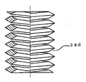
バネ部材24dは、図4に示すように、菱形断面のステンレス角線材をコイル状に巻線成形することにより構成されており、そのピッチがネジ部24cのネジピッチ及び後述する支軸23の下端に形成されたネジ部23aのネジピッチと同じに設定されていると共に、その内径がネジ部24c及びネジ部23aの内径とほぼ同じに設定されている。
これにより、バネ部材24dは、その下端がネジ部24cに外挿される。As shown in FIG. 4, the
Thereby, the lower end of the
これに対して、バネ部材24dの上端は、上述した支軸23の下端に設けられたネジ部23aに外挿される。その際、バネ部材24dの内側で、支軸23の下端面とネジ部24cの上端面との間隔が1mm程度となるように、支軸23とネジ部24cが垂直方向に突き合わされた状態で、バネ部材24dにより保持される。
これにより、上述した間隔の領域において、バネ部材24dが伸縮可能であるので、支軸23は、その下端において、バネ部材24dを介して、ネジ部24cに対して、即ち固定板11の上面に対して、揺動可能に支持される。On the other hand, the upper end of the
Accordingly, since the
本発明実施形態による除振装置10は、以上のように構成されており、例えば精密機器15が搭載されると、図1に示すように、精密機器15及び可動板12の重量による荷重が、各コイルバネ13に印可され、この荷重によって、各コイルバネ13が弾性変形により撓んた状態で、可動板12を浮遊状態に支持する。
従って、各ダンパー部20においては、各コイルバネ13の弾性変形による縮小に対応して、受け部材21の中空部内でダンパー部22が垂直方向に摺動して、図示した高さ位置H1に静止する。The
Accordingly, in each
このような状態において、図5に示すように、例えば精密機器15の操作時等において、操作者が精密機器15に対して水平方向に力を加える等によって、精密機器15または可動板12に対して矢印A方向に振動等により変位が生ずると、この変位によって、各コイルバネ13の中心軸が図示のように角度θだけ傾斜する。
このとき、ダンパー部20の受け部材21も可動板12と同じ量だけ矢印A方向に変位するが、支軸23が固定板11に対して揺動手段24により揺動可能に支持されているので、支軸23が揺動により傾斜することによって、ダンパー材22が大きく曲げ変形を生ずる。この曲げ変形により、ダンパー材22によるエネルギー吸収量が増大するので、除振装置10における水平方向の自由振動の収束が促進される。
尚、支軸23が揺動する際の揺動手段24即ちバネ部材24bの揺動方向へのバネ定数が小さいので、除振装置10における水平方向の固有振動数は、コイルバネ13の水平方向のバネ定数によって決まる。In such a state, as shown in FIG. 5, for example, when the
At this time, the receiving
Since the spring constant in the swinging direction of the swinging means 24, that is, the
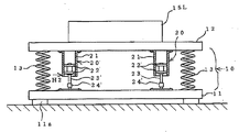
次に、上述した精密機器15よりも軽量の精密機器15Lが可動板12上に搭載される場合について説明する。
図6において、精密機器15L及び可動板12の重量による荷重が、各コイルバネ13に印可され、この荷重によって、各コイルバネ13が弾性変形により撓んた状態で、可動板12を浮遊状態に支持する。
この場合、各コイルバネ13の撓み量は、精密機器15Lの重量が精密機器15の重量より軽いので、その重量差だけ、各コイルバネ13に印可される荷重が低減する。従って、図6に示すように、各コイルバネ13の撓み量が減少することになる。Next, a case where a precision instrument 15L that is lighter than the
In FIG. 6, a load due to the weight of the
In this case, since the weight of the precision device 15L is lighter than the weight of the
従って、各ダンパー部20においては、各コイルバネ13の弾性変形による縮小に対応して、受け部材21の中空部内でダンパー部22が垂直方向に摺動して、受け部材21は、図1に示した高さ位置H1より高い高さ位置H2に静止する。
即ち、各ダンパー部20において、ダンパー材22は、受け部材21の下端寄りに位置する。
このとき、ダンパー材22は、円筒状の受け部材21内を軸方向に移動するだけであるので、ダンパー材22の外周縁の受け部材21の内面に対する接触状態はほぼ同じである。従って、精密機器15がより軽い精密機器15Lに変更されても、ダンパー材22の減衰特性やバネ特性は殆ど変化しない。Accordingly, in each
That is, in each
At this time, since the
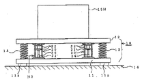
また、上述した精密機器15よりも重い精密機器15Hが可動板12上に搭載される場合について説明する。
図7において、精密機器15H及び可動板12の重量による荷重が、各コイルバネ13に印可され、この荷重によって、各コイルバネ13が弾性変形により撓んた状態で、可動板12を浮遊状態に支持する。
この場合、各コイルバネ13の撓み量は、精密機器15Hの重量が精密機器15の重量より重いので、その重量差だけ、各コイルバネ13に印可される荷重が増大する。従って、図7に示すように、各コイルバネ13の撓み量が増大することになる。A case where a precision device 15H heavier than the above-described
In FIG. 7, a load due to the weight of the precision device 15H and the
In this case, the amount of deflection of each
従って、各ダンパー部20においては、各コイルバネ13の弾性変形による圧縮に対応して、受け部材21の中空部内でダンパー材22が垂直方向に摺動して、受け部材21は、図1に示した高さ位置H1より低い高さ位置H3に静止する。
即ち、各ダンパー部20において、ダンパー材22は、受け部材21の上端寄りに位置する。Accordingly, in each
That is, in each
このようにして、異なる重量の精密機器15,15Lまたは15Hが可動板12上に搭載されたとしても、ダンパー材22は、円筒状の受け部材21内を軸方向に移動するだけであるので、ダンパー材22の外周縁の受け部材21の内面に対する接触状態はほぼ同じである。従って、精密機器15がより軽い精密機器15Lあるいは、より重い精密機器15Hに変更されても、ダンパー材22の減衰特性やバネ特性は殆ど変化しない。 In this way, even if
このようにして、本発明実施形態による除振装置10によれば、可動板12上に搭載する精密機器15の重量が変化したとしても、ダンパー材22の接触状態を殆ど変化させることなく、即ちダンパー材22の減衰特性やバネ特性を殆ど変化させず、また除振特性の劣化を抑制することができる。 Thus, according to the
図8は、本発明による除振装置の第二の実施形態におけるダンパー部の構成を示している。
図8において、この除振装置は、図1及び図2に示した除振装置10とほぼ同様の構成であるので、同じ構成要素には同じ符号を付して、その説明を省略する。
この除振装置は、図1及び図2に示した除振装置10とは、ダンパー部20の構成のみが異なっている。FIG. 8 shows the configuration of the damper portion in the second embodiment of the vibration isolator according to the present invention.
In FIG. 8, the vibration isolator has substantially the same configuration as that of the
This vibration isolator differs from the
即ち、図8において、この除振装置では、ダンパー部30は、受け部材31と、ダンパー材22と、支軸23と、から構成されている。 In other words, in FIG. 8, in this vibration isolator, the
受け部材31は、内壁面が上方に向かって先細の円錐台状に形成されており、上端がネジ31aにより可動板12の下面に固定されている。
ここで、受け部材31の円錐台状の中空部は、その下端の内径がダンパー材22の外径より大きく、また上端の内径がダンパー材22の外径より小さく、さらに中空部の軸方向(垂直方向)の下方から四分の一の高さ位置における内径が、ダンパー材22の外径と同じ大きさとなるように形成されている。The receiving
Here, the frustoconical hollow portion of the receiving
このような構成の除振装置によれば、図1に示した除振装置10と同様に作用すると共に、重い精密機器15Hが可動板12上に搭載される場合には、図9(A)に示すように、各コイルバネ13の撓み量が増大し、各ダンパー部30においては、各コイルバネ13の弾性変形による圧縮に対応して、受け部材31の中空部内でダンパー材22が垂直方向に摺動して、受け部材31は、図8に示した高さ位置より下方に移動する。 According to the vibration isolator having such a configuration, the same effect as that of the
このとき、ダンパー材22は、受け部材31の内壁面の内径が徐々に小さくなるので、外周が内側に圧縮され、図9(A)に示すように、傘状に変形する。これにより、ダンパー材22の減衰特性が増大すると共に、バネ特性も変化し、バネ定数が増大する。
従って、重い精密機器15Hが自由振動する際のダンパー材22によるエネルギー吸収量が増大して、その減衰が大きくなる。これにより、重い精密機器15Hの自由振動の収束が促進される。At this time, since the inner diameter of the inner wall surface of the receiving
Therefore, the amount of energy absorbed by the
さらに、コイルバネ13とダンパー材22による合成バネ定数も増大する。前述した式1に基づいて、除振装置10の固有振動数はバネ定数と質量の比で決まるので、重い精密機器15Hの搭載時には、バネ定数が大きくなると、その比の変化が小さくなるので、除振装置の固有振動数の変化も減少することになる。 Furthermore, the composite spring constant by the
これに対して、軽い精密機器15Lが可動板12上に搭載される場合には、図9(B)に示すように、各コイルバネ13の撓み量が減少し、各ダンパー部30においては、各コイルバネ13の弾性変形による伸長に対応して、受け部材31の中空部内でダンパー材22が垂直方向に摺動して、受け部材31は、図8に示した高さ位置より上方に移動する。 On the other hand, when the light precision device 15L is mounted on the
このとき、ダンパー材22は、受け部材31の内壁面の内径が徐々に大きくなるので、外周に対する押圧力が減少すると共に、下方のダンパー材22は、その外周が受け部材31の内壁面から離反する。これにより、ダンパー材22の減衰特性が減少すると共に、バネ特性も変化し、バネ定数が小さくなる。
従って、軽い精密機器15Lが自由振動する際のダンパー材22によるエネルギー吸収量が減少して、その減衰が小さくなる。これにより、軽い精密機器15Lの自由振動の収束が過減衰になることを防ぐ。
さらに、コイルバネ13とダンパー材22による合成バネ定数も減少するので、除振装置の固有振動数の変化も減少することになる。At this time, since the inner diameter of the inner wall surface of the receiving
Accordingly, the amount of energy absorbed by the
Furthermore, since the composite spring constant by the
図10は、本発明による除振装置の第三の実施形態におけるダンパー部の構成を示している。
図10において、この除振装置は、図1及び図2に示した除振装置10とほぼ同様の構成であるので、同じ構成要素には同じ符号を付して、その説明を省略する。
この除振装置は、図1及び図2に示した除振装置10とは、ダンパー部20の構成のみが異なっている。FIG. 10 shows the configuration of the damper portion in the third embodiment of the vibration isolator according to the present invention.
10, this vibration isolator has substantially the same configuration as that of the
This vibration isolator differs from the
即ち、図10において、この除振装置では、ダンパー部20における揺動手段24は、コイルバネ状のバネ部材24dの代わりに、例えばゴム製のチューブ部材から成る中空円筒状の連結部材24eを備えている。
また、固定部材24a上には、ネジ部24cの代わりに、円柱状部24fが備えられている。
そして、円柱状部24fの上端の外周面及び支軸23の下端の外周面には、円周溝24g,23bが形成されている。That is, in FIG. 10, in this vibration isolator, the swinging means 24 in the
Further, on the fixing member 24a, a cylindrical portion 24f is provided instead of the
Then, circumferential grooves 24g and 23b are formed on the outer peripheral surface at the upper end of the cylindrical portion 24f and the outer peripheral surface at the lower end of the
ここで、連結部材24eの内径は、円柱状部24f及び支軸23の外径より小さく選定されている。
これにより、連結部材24eの上端及び下端が、支軸23の下端及び円柱状部24fの上端に被嵌されたとき、連結部材24eが、円周溝24g,23b内に食い込むことにより、連結部材24eの支軸23及び円柱状部24fからの脱落が防止される。
その際、連結部材24e内において、支軸23の下端面と円柱状部24fの上端面との間隔が1mm程度であることにより、連結部材24eがこの間隔の領域において伸縮可能であるので、支軸23は、その下端において、連結部材24eを介して、即ち固定板11に対して揺動可能に支持される。Here, the inner diameter of the connecting member 24e is selected to be smaller than the outer diameters of the cylindrical portion 24f and the
Thereby, when the upper end and lower end of the connecting member 24e are fitted on the lower end of the
At that time, since the interval between the lower end surface of the
このような構成の除振装置によれば、図1及び図2に示した除振装置10と同様に作用する。 According to the vibration isolator having such a configuration, it operates in the same manner as the
図11は、本発明による除振装置の第四の実施形態におけるダンパー部の構成を示している。
図11において、この除振装置は、図10に示した除振装置におけるダンパー部とほぼ同様の構成であるので、同じ構成要素には同じ符号を付して、その説明を省略する。
この除振装置は、図10に示した除振装置とは、ダンパー部20の構成のみが異なっている。FIG. 11 shows the configuration of the damper portion in the fourth embodiment of the vibration isolator according to the present invention.
In FIG. 11, the vibration isolator has substantially the same configuration as the damper portion in the vibration isolator illustrated in FIG. 10, and thus the same components are denoted by the same reference numerals and description thereof is omitted.
This vibration isolator differs from the vibration isolator shown in FIG. 10 only in the configuration of the
即ち、図11において、この除振装置では、ダンパー部20における揺動手段24は、ゴム製のチューブ部材から成る連結部材24eの代わりに、線バネ24hを備えている。
固定部材24a上の円柱状部24fの上端面及び支軸23の下端面には、それぞれ中心に穴24i,23cが備えられている。That is, in FIG. 11, in this vibration isolator, the swinging means 24 in the
Holes 24i and 23c are provided at the centers of the upper end surface of the cylindrical portion 24f on the fixing member 24a and the lower end surface of the
これにより、線バネ24hの上端及び下端が、支軸23の下端面の穴23c及び円柱状部24fの上端面の穴24iに圧入されて、線バネ24hが、支軸23及び円柱状部24fに対して同心に固定される。
その際、支軸23の下端面と円柱状部24fの上端面との間隔が1mm程度であることにより、線バネ24hがこの間隔の領域において弾性変形可能であるので、支軸23は、その下端において、線バネ24hを介して、固定板11に対して揺動可能に支持される。Thereby, the upper end and the lower end of the wire spring 24h are press-fitted into the hole 23c on the lower end surface of the
At that time, since the distance between the lower end surface of the
このような構成の除振装置によれば、図1及び図2に示した除振装置10と同様に作用する。 According to the vibration isolator having such a configuration, it operates in the same manner as the
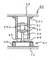
図12は、本発明による除振装置の第五の実施形態におけるダンパー部の構成を示している。
図12において、この除振装置は、図1及び図2に示した除振装置とほぼ同様の構成であるので、同じ構成要素には同じ符号を付して、その説明を省略する。
この除振装置は、図1及び図2に示した除振装置10とは、ダンパー部20の構成のみが異なっている。FIG. 12 shows the configuration of the damper portion in the fifth embodiment of the vibration isolator according to the present invention.
In FIG. 12, the vibration isolator has substantially the same configuration as the vibration isolator shown in FIGS. 1 and 2, and therefore, the same components are denoted by the same reference numerals and description thereof is omitted.
This vibration isolator differs from the
即ち、図12において、この除振装置では、ダンパー部40は、揺動手段24の代わりに、揺動手段41を備えている。
揺動手段41は、偏平な中空円筒状の固定部材42と、固定部材42の上端に取り付けられた円板状の弾性部材43と、弾性部材43の中心の上面に取り付けられたフランジ44と、から構成されている。That is, in FIG. 12, in this vibration isolation device, the
The swinging means 41 includes a flat hollow cylindrical fixing member 42, a disk-like
固定部材42は、例えば金属パイプ等から構成されており、固定板11上に固定されている。
弾性部材43は、例えばゴム板から構成されており、その外周縁が固定部材42の上端外周に固定されている。
フランジ44は、支軸23の下端に一体的に取り付けられていると共に、弾性部材43の中心において、その上面に同軸に固着されている。The fixing member 42 is made of, for example, a metal pipe or the like, and is fixed on the fixing
The
The
これにより、支軸23は、その下端がフランジ44,弾性部材43及び固定部材42を介して、固定板11に取り付けられる。
このとき、支軸23は、弾性部材43の表面に対して垂直に取り付けられると共に、弾性部材43の弾性変形によって、固定板11に対して揺動可能に支持されることになる。As a result, the lower end of the
At this time, the
このような構成の除振装置によれば、図1及び図2に示した除振装置10と同様に作用する。 According to the vibration isolator having such a configuration, it operates in the same manner as the
なお、前記ダンパー部における受け部材、ダンパー材及び支軸が、無負荷状態で、前記固定板及び可動板の一方から他方に向かって中心軸に傾斜して配置されていても良い。 In addition, the receiving member, the damper material, and the support shaft in the damper portion may be arranged so as to be inclined toward the central axis from one of the fixed plate and the movable plate to the other in an unloaded state.
上述した本発明実施形態による除振装置10においては、可動板12は、固定板11に対して、四隅付近に配置された四個のコイルバネ13により支持され、各コイルバネ13に隣接しては位置された四個のダンパー部20により除振されるように構成されているが、これに限らず、精密機器15,15Lまたは15Hが搭載される可動板12が固定板11に対してバランスよく支持されれば、少なくとも三個以上のコイルバネ13及びダンパー部20により支持されるようにしてもよいことは明らかである。
その際、各コイルバネ13及びダンパー部20の配置場所は、これらの加重平均位置が精密機器15の重心と垂直方向に整列するように選定されればよい。In the
At this time, the arrangement locations of the coil springs 13 and the
上述した実施形態においては、各ダンパー部20,30,40は、それぞれ対応するコイルバネ13に対してX方向内側に隣接して配置されているが、これに限らず、各ダンパー部20,30,40は、それぞれ対応するコイルバネ13に対して、Y方向内側、あるいは固定板11及び可動板12の中心寄りに配置されていてもよい。 In the above-described embodiment, each
上述した実施形態においては、固定板11に対して可動板12を支持するために、コイルバネ13が使用されているが、これに限らず、他の種類の弾性部材が使用されてもよいことは明らかである。 In the above-described embodiment, the
さらに、上述した実施形態においては、精密機器15,15L,15Hの除振を行なう場合について説明したが、他の各種機器装置、特に精密機器類等の除振のために使用してもよいことは明らかである。 Further, in the above-described embodiment, the case of performing vibration isolation of the
以上述べたように、本発明によれば、荷重が変化しても、振動に対する減衰特性及びバネ特性の変化が抑制され、除振性能の劣化が低減される、極めて優れた除振装置が提供され得る。 As described above, according to the present invention, even if the load changes, a very excellent vibration isolation device is provided in which the change in the damping characteristics and the spring characteristics against vibration is suppressed and the deterioration of the vibration isolation performance is reduced. Can be done.
10 除振装置
11 固定板
12 可動板
13 コイルバネ(弾性部材)
14 作業台
15 精密機器
15H 重い精密機器
15L 軽い精密機器
20,30,40 ダンパー部
21,31 受け部材
22 ダンパー材
23 支軸
24,41 揺動手段
42 固定部材
43 弾性部材
44 フランジ10
14 Work table 15 Precision instrument 15H Heavy precision instrument 15L
Claims (9)
前記各ダンパー部が、それぞれ前記固定板または可動板に固定された受け部材と、前記受け部材内で同軸に且つ摺動可能に配置された粘弾性体から成る円板状のダンパー材と、前記ダンパー材の中心付近に一端が連結された支軸と、から構成されており、
前記支軸の他端が、前記可動板または固定板に対して揺動手段を介して揺動可能に支持されている、
ことを特徴とする除振装置。It is movable relative to the fixed plate through at least three elastic members disposed between the fixed plate arranged horizontally and the fixed plate, and interposed between the fixed plate and the fixed plate. A movable plate supported by the damper plate, and a damper portion disposed adjacent to each elastic member between the fixed plate and the movable plate, and
Each of the damper portions is a receiving member fixed to the fixed plate or the movable plate, a disk-shaped damper material made of a viscoelastic body coaxially and slidably disposed in the receiving member, It consists of a support shaft with one end connected near the center of the damper material,
The other end of the support shaft is supported so as to be swingable with respect to the movable plate or the fixed plate via a swinging means.
A vibration isolator characterized by that.
Priority Applications (1)
| Application Number | Priority Date | Filing Date | Title |
|---|---|---|---|
| JP2010294889A JP2012141027A (en) | 2010-12-28 | 2010-12-28 | Vibration isolator |
Applications Claiming Priority (1)
| Application Number | Priority Date | Filing Date | Title |
|---|---|---|---|
| JP2010294889A JP2012141027A (en) | 2010-12-28 | 2010-12-28 | Vibration isolator |
Publications (1)
| Publication Number | Publication Date |
|---|---|
| JP2012141027A true JP2012141027A (en) | 2012-07-26 |
Family
ID=46677490
Family Applications (1)
| Application Number | Title | Priority Date | Filing Date |
|---|---|---|---|
| JP2010294889A Pending JP2012141027A (en) | 2010-12-28 | 2010-12-28 | Vibration isolator |
Country Status (1)
| Country | Link |
|---|---|
| JP (1) | JP2012141027A (en) |
Cited By (11)
| Publication number | Priority date | Publication date | Assignee | Title |
|---|---|---|---|---|
| CN103016587A (en) * | 2012-12-12 | 2013-04-03 | 上海交通大学 | Semi-driving type variable stiffness dynamic vibration absorber made from conical springs |
| JP2014077458A (en) * | 2012-10-09 | 2014-05-01 | Unirock:Kk | Vibration isolator |
| CN107717892A (en) * | 2017-11-21 | 2018-02-23 | 浙江亚普自动化设备有限公司 | A kind of workbench with shock-absorbing function |
| CN108487207A (en) * | 2018-04-07 | 2018-09-04 | 王宏伟 | A kind of floating algae collecting device of sewage disposal |
| CN108745951A (en) * | 2018-07-06 | 2018-11-06 | 合肥格骄电子科技有限公司 | A kind of stable color selector |
| CN109441607A (en) * | 2018-11-14 | 2019-03-08 | 刘嘉禾梓 | A kind of energy-saving and environment-friendly bus waste gas recovering device |
| CN109973466A (en) * | 2019-03-05 | 2019-07-05 | 广西玉柴专用汽车有限公司 | A kind of supporting structure of horizontal telescoping oil cylinder |
| CN112520359A (en) * | 2020-10-29 | 2021-03-19 | 河北汉光重工有限责任公司 | Balance middle position composite vibration damping device for ship-based missile transportation |
| WO2022077666A1 (en) * | 2020-10-15 | 2022-04-21 | 苏州莱锦机电自动化有限公司 | Damping apparatus for electromechanical device |
| CN114658796A (en) * | 2022-02-26 | 2022-06-24 | 华为数字能源技术有限公司 | Vibration isolator and box body |
| CN116624555A (en) * | 2023-06-13 | 2023-08-22 | 西北工业大学 | A vibration isolation method with time-varying vibration isolator position and vibration isolation base |
-
2010
- 2010-12-28 JP JP2010294889A patent/JP2012141027A/en active Pending
Cited By (13)
| Publication number | Priority date | Publication date | Assignee | Title |
|---|---|---|---|---|
| JP2014077458A (en) * | 2012-10-09 | 2014-05-01 | Unirock:Kk | Vibration isolator |
| CN103016587A (en) * | 2012-12-12 | 2013-04-03 | 上海交通大学 | Semi-driving type variable stiffness dynamic vibration absorber made from conical springs |
| CN107717892A (en) * | 2017-11-21 | 2018-02-23 | 浙江亚普自动化设备有限公司 | A kind of workbench with shock-absorbing function |
| CN108487207A (en) * | 2018-04-07 | 2018-09-04 | 王宏伟 | A kind of floating algae collecting device of sewage disposal |
| CN108745951A (en) * | 2018-07-06 | 2018-11-06 | 合肥格骄电子科技有限公司 | A kind of stable color selector |
| CN109441607A (en) * | 2018-11-14 | 2019-03-08 | 刘嘉禾梓 | A kind of energy-saving and environment-friendly bus waste gas recovering device |
| CN109973466A (en) * | 2019-03-05 | 2019-07-05 | 广西玉柴专用汽车有限公司 | A kind of supporting structure of horizontal telescoping oil cylinder |
| CN109973466B (en) * | 2019-03-05 | 2024-02-09 | 广西玉柴专用汽车有限公司 | Supporting structure of horizontal telescopic cylinder |
| WO2022077666A1 (en) * | 2020-10-15 | 2022-04-21 | 苏州莱锦机电自动化有限公司 | Damping apparatus for electromechanical device |
| CN112520359A (en) * | 2020-10-29 | 2021-03-19 | 河北汉光重工有限责任公司 | Balance middle position composite vibration damping device for ship-based missile transportation |
| CN114658796A (en) * | 2022-02-26 | 2022-06-24 | 华为数字能源技术有限公司 | Vibration isolator and box body |
| CN114658796B (en) * | 2022-02-26 | 2023-11-03 | 华为数字能源技术有限公司 | Vibration isolator and box |
| CN116624555A (en) * | 2023-06-13 | 2023-08-22 | 西北工业大学 | A vibration isolation method with time-varying vibration isolator position and vibration isolation base |
Similar Documents
| Publication | Publication Date | Title |
|---|---|---|
| JP5265214B2 (en) | Air bearing considering high frequency resonance | |
| JP3614755B2 (en) | Omnidirectional vibration isolation system | |
| CN113464603B (en) | A Multidirectional Adjustable Tuning Dynamic Damper | |
| US6991077B2 (en) | Vibration damping device | |
| KR20160036455A (en) | Damper | |
| JP2020500281A (en) | Vibration suspension system | |
| CN103615488A (en) | Spring steel disc type dynamic vibration absorber with adjustable rigidity | |
| CN113503336A (en) | Constant-quasi-zero-stiffness vibration isolator | |
| CN106677366A (en) | Tuned mass damping device | |
| CN104832591A (en) | Composite stiffness damping shock absorber | |
| JP2010084834A (en) | Simplified dynamic vibration absorber and vibration damping method | |
| JP2007120744A (en) | Vibration control device | |
| JP2010031953A (en) | Vibration damping-vibration control device by compression coil spring | |
| JP2013079703A (en) | Vibration isolating device | |
| JP6289929B2 (en) | Structure damping device and specification setting method thereof | |
| JP2008202608A (en) | Vibration control device | |
| CN116591331A (en) | An ultra-low frequency lever tuned mass damper and its design method | |
| KR101328791B1 (en) | Vibration isolation device | |
| JP2015117791A (en) | Vibration damper and suspension using the same | |
| JP2004360784A (en) | Compact damping device and compact damping table | |
| JP2009263864A (en) | Vibration control device for floor vibration and floor impact sound | |
| JP2010127391A (en) | Active vibration controller and actuator used for the same | |
| JP5498367B2 (en) | Damper and vibration isolator for machined parts and machining method of machined parts | |
| JP2006322534A (en) | Vibration isolation device | |
| JP2016138578A (en) | Dynamic vibration absorber |