JP2012141502A - Viewpoint position detecting device, method for detecting viewpoint position, and stereographic display device - Google Patents
Viewpoint position detecting device, method for detecting viewpoint position, and stereographic display device Download PDFInfo
- Publication number
- JP2012141502A JP2012141502A JP2011000657A JP2011000657A JP2012141502A JP 2012141502 A JP2012141502 A JP 2012141502A JP 2011000657 A JP2011000657 A JP 2011000657A JP 2011000657 A JP2011000657 A JP 2011000657A JP 2012141502 A JP2012141502 A JP 2012141502A
- Authority
- JP
- Japan
- Prior art keywords
- viewpoint position
- image
- subject
- position detection
- unit
- Prior art date
- Legal status (The legal status is an assumption and is not a legal conclusion. Google has not performed a legal analysis and makes no representation as to the accuracy of the status listed.)
- Pending
Links
- 238000000034 method Methods 0.000 title claims description 43
- 239000003550 marker Substances 0.000 claims abstract description 72
- 238000001514 detection method Methods 0.000 claims abstract description 57
- 238000003384 imaging method Methods 0.000 claims abstract description 42
- 230000001360 synchronised effect Effects 0.000 claims description 3
- 238000010586 diagram Methods 0.000 description 6
- 210000003128 head Anatomy 0.000 description 6
- 230000004397 blinking Effects 0.000 description 5
- 230000005484 gravity Effects 0.000 description 4
- 239000011521 glass Substances 0.000 description 3
- 239000004973 liquid crystal related substance Substances 0.000 description 3
- 238000005286 illumination Methods 0.000 description 2
- 230000000295 complement effect Effects 0.000 description 1
- 230000000694 effects Effects 0.000 description 1
- 238000002372 labelling Methods 0.000 description 1
- 229910044991 metal oxide Inorganic materials 0.000 description 1
- 150000004706 metal oxides Chemical class 0.000 description 1
- 230000003287 optical effect Effects 0.000 description 1
- 230000000737 periodic effect Effects 0.000 description 1
- 230000002093 peripheral effect Effects 0.000 description 1
- 239000004065 semiconductor Substances 0.000 description 1
- 230000009466 transformation Effects 0.000 description 1
Images





Landscapes
- Controls And Circuits For Display Device (AREA)
- Devices For Indicating Variable Information By Combining Individual Elements (AREA)
- Mechanical Light Control Or Optical Switches (AREA)
- Control Of Driving Devices And Active Controlling Of Vehicle (AREA)
- Instrument Panels (AREA)
- Testing, Inspecting, Measuring Of Stereoscopic Televisions And Televisions (AREA)
Abstract
【課題】実装コストの低い画像処理から構成され、また、明るさが常に変動する環境下でも安定して対象者の視点位置を検出することが可能な視点位置検出装置、視点位置検出方法及び立体表示装置を提供する。
【解決手段】視点位置検出装置は、1つ以上の発光マーカー12aを備え対象者2の頭部に装着可能であるマーカー部12と、対象者2を撮像する撮像部11と、撮像部11が撮像した対象者2の画像から対象者2の視点位置を検出する視点位置検出部14と、を備える。視点位置検出部14は、撮像部11が撮像した対象者2の画像上の発光マーカー12aの位置を検出し、発光マーカー12aの位置に基づいて対象者2の視点位置を検出する。
【選択図】図1A viewpoint position detection apparatus, a viewpoint position detection method, and a three-dimensional view that are configured by image processing with low mounting cost and that can stably detect the viewpoint position of a target person even in an environment where brightness constantly fluctuates. A display device is provided.
A viewpoint position detection device includes a marker unit 12 that includes one or more light-emitting markers 12a and that can be mounted on the head of a subject 2, an imaging unit 11 that captures the subject 2, and an imaging unit 11. A viewpoint position detection unit 14 that detects the viewpoint position of the subject 2 from the captured image of the subject 2. The viewpoint position detection unit 14 detects the position of the light emitting marker 12a on the image of the subject 2 captured by the imaging unit 11, and detects the viewpoint position of the subject 2 based on the position of the light emitting marker 12a.
[Selection] Figure 1
Description
本発明は、対象者の視点位置を検出する視点位置検出装置、視点検出方法及び画像を立体的に表示可能な立体表示装置に関する。 The present invention relates to a viewpoint position detection device that detects a viewpoint position of a subject, a viewpoint detection method, and a stereoscopic display device that can stereoscopically display an image.
従来、車両のフロントガラスに立体的な画像を表示可能な車両用表示装置であるヘッドアップディスプレイ(Head-Up Display;HUD)としては、例えば、特許文献1に開示されるものがある。この車両用表示装置は、表示画像の元となる立体データを記憶した記憶手段と、運転者の視点位置検出手段と、視点位置に基づいて立体データから表示画像を得る画像処理手段とから構成される。そして、運転者の視点位置を検出し、その位置に基づいて立体データから表示画像データを生成し、HUDに表示する。
また、立体的に画像を表示可能な車両用表示装置としては、例えば、特許文献2に開示されるように、左目用画像及び右目用画像を時分割で液晶表示パネルに表示させるとともに、運転者の視点位置を検出し、その位置に応じて液晶表示パネルを透過する照明光の光軸を変化させるものがある。
Conventionally, as a head-up display (HUD) that is a vehicle display device capable of displaying a three-dimensional image on a windshield of a vehicle, for example, there is one disclosed in
In addition, as a vehicle display device capable of displaying an image three-dimensionally, for example, as disclosed in Patent Document 2, a left-eye image and a right-eye image are displayed on a liquid crystal display panel in a time-sharing manner, and a driver There is one that detects the position of the viewpoint and changes the optical axis of the illumination light transmitted through the liquid crystal display panel according to the position.
特許文献1及び2に記載の車両用表示装置において、運転者(対象者)の視点位置を検出する方法としては、運転者の顔を撮像した画像から運転者の目を割り出して視点位置を検出する処理がある。しかしながら、かかる方法は高度な画像認識処理が要求される為に処理が複雑になり、実装コストが高いという問題点があった。また、移動する車両内のように,周囲の明るさが常に変動している状況では、検出対象である運転者の画像も変化する為に安定して視点位置を検出することが困難であった。
In the vehicle display devices described in
そこで、本発明は、実装コストの低い画像処理から構成され、また、明るさが常に変動する環境下でも安定して対象者の視点位置を検出することが可能な視点位置検出装置、視点位置検出方法及び立体表示装置を提供することを目的とする。 Therefore, the present invention is composed of image processing with low mounting cost, and a viewpoint position detection device and viewpoint position detection capable of stably detecting the viewpoint position of the subject even in an environment where the brightness constantly fluctuates. It is an object to provide a method and a stereoscopic display device.
上記目的を達成するため、本発明の視点位置検出装置は、
1つ以上の発光マーカーを備え対象者の頭部に装着可能であるマーカー部と、前記対象者を撮像する撮像部と、前記撮像部が撮像した前記対象者の画像から前記対象者の視点位置を検出する視点位置検出部と、を備える視点位置検出装置であって、
前記視点位置検出部は、前記撮像部が撮像した前記対象者の画像上の前記発光マーカーの位置を検出し、前記発光マーカーの位置に基づいて前記対象者の視点位置を検出することを特徴とする。
In order to achieve the above object, the viewpoint position detection device of the present invention provides:
A marker unit that includes one or more light-emitting markers and that can be mounted on the head of the subject; an imaging unit that images the subject; and a viewpoint position of the subject from the image of the subject captured by the imaging unit A viewpoint position detecting unit for detecting
The viewpoint position detection unit detects the position of the light emitting marker on the image of the subject captured by the imaging unit, and detects the viewpoint position of the subject based on the position of the light emitting marker. To do.
上記目的を達成するため、本発明の視点位置検出方法は、
対象者を撮像部で撮像し、前記撮像部が撮像した前記対象者の画像から前記対象者の視点位置を検出する視点位置方法であって、
前記撮像者は1つ以上の発光マーカーを備えるマーカー部を頭部に装着し、前記撮像部が撮像した前記対象者の画像上の前記発光マーカーの位置を検出し、前記発光マーカーの位置に基づいて前記対象者の視点位置を検出することを特徴とする。
In order to achieve the above object, the viewpoint position detection method of the present invention includes:
A viewpoint position method of capturing an image of a target person with an imaging unit, and detecting the viewpoint position of the target person from the image of the target person captured by the imaging unit,
The imager wears a marker unit including one or more light emitting markers on the head, detects the position of the light emitting marker on the image of the subject imaged by the image capturing unit, and based on the position of the light emitting marker The viewpoint position of the subject is detected.
上記目的を達成するため、本発明の立体表示装置は、
立体的に視認可能な立体画像を表示する画像表示部を備える立体表示装置であって、
請求項1または2に記載の視点位置検出装置と、前記視点位置検出装置によって検出された対象者の視点位置に基づいて前記立体画像を生成する画像表示制御部と、を備えてなることを特徴とする。
In order to achieve the above object, the stereoscopic display device of the present invention provides:
A stereoscopic display device including an image display unit that displays a stereoscopically viewable stereoscopic image,
The viewpoint position detection device according to
上記目的を達成するため、本発明の立体表示装置は、
表示パネルに右目用画像と左目用画像を所定の時間間隔で交互に表示させることにより立体的に視認可能な立体画像をミラーに反射させて表示するヘッドアップディスプレイ(HUD)を備える立体表示装置であって、
請求項1または2に記載の視点位置検出装置と、前記視点位置検出装置によって検出された対象者の視点位置に基づいて前記ヘッドアップディスプレイを制御するHUD制御部と、を備え、
前記HUD制御部は、前記視点位置検出装置によって検出された対象者の視点位置に基づいて前記右目用画像及び前記左目用画像を生成する及び/あるいは前記対象者の視点位置に対応するように前記ミラーの回転角を制御することを特徴とする。
In order to achieve the above object, the stereoscopic display device of the present invention provides:
A stereoscopic display device including a head-up display (HUD) that displays a stereoscopically visible stereoscopic image by reflecting it on a mirror by alternately displaying a right-eye image and a left-eye image on a display panel at predetermined time intervals. There,
The viewpoint position detection device according to
The HUD control unit generates the right-eye image and the left-eye image based on the viewpoint position of the subject detected by the viewpoint position detection device and / or corresponds to the viewpoint position of the subject. The rotation angle of the mirror is controlled.
本発明によれば、実装コストの低い画像処理から構成され、また、明るさが常に変動する環境下でも安定して視点位置を検出することが可能な視点位置検出装置、視点位置検出方法及び立体表示装置を提供できる。 According to the present invention, a viewpoint position detection device, a viewpoint position detection method, and a three-dimensional view that are configured by image processing with low mounting cost and can stably detect a viewpoint position even in an environment in which brightness constantly fluctuates. A display device can be provided.
以下に、本発明の実施形態を図を参照して説明する。 Embodiments of the present invention will be described below with reference to the drawings.
(第1実施形態)
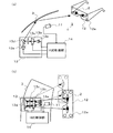
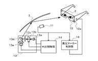
図1(a)及び(b)は、本発明の第1実施形態に係る車載立体表示装置1の概略構成を示す図である。本実施形態に係る車載立体表示装置1は、撮像部11と、マーカー付き眼鏡12と、ヘッドアップディスプレイ(HUD)13と、HUD制御部14と、から構成され、視点位置検出装置を含むものである。
(First embodiment)
1A and 1B are diagrams showing a schematic configuration of an in-vehicle
撮像部11は、運転者(対象者)2の顔を撮像するものであり、CCD(Charged Coupled Device)やCMOS(Complementary Metal Oxide Semiconductor)等の周知の撮像素子と、それを制御する周辺回路やレンズ等から構成される。撮像部11は、マーカー付き眼鏡12を頭部に装着した運転者2の正面に設置される。撮像部11は、撮像した運転者2の顔の画像を、奇数フィールドと偶数フィールドからなる所謂インターレース方式でビデオ信号(出力映像信号)に変換し、出力する。インターレース方式のビデオ信号の規格としては、例えばNTSC(National Television System Committee)方式がある。
The
マーカー付き眼鏡12(マーカー部の一例)は、運転者2が頭部に装着可能なものである。マーカー付き眼鏡12は、撮像部11が運転者2の顔を撮像した際に、運転者の顔と共に撮像可能な位置に少なくとも1つ以上(本実施形態においては4つ)の発光マーカー12aを備える。発光マーカー12aは例えばLED等の発光素子からなり、本実施形態においては電源が投入されると常時点灯するものである。なお、発光マーカー12aは、運転者2からは発光が認識されない赤外線LED等を用いても良く、また、照明光を反射する反射シールからなるものであっても良い。
The
HUD13は、HUD制御部14からの制御信号に基づいて、運転者2の左右の目にそれぞれ別々の画像をフロントガラス3に反射させて交互に投影することで、立体感のある表示を実現するものである。HUD13は、光源13aと、表示パネル13bと、結像レンズ13cと、ミラー13dと、ミラー駆動部13eとから構成される。
Based on the control signal from the
光源13aは、2つの光源から構成され、それぞれ運転者2の左右の目に対応して、独
立して発光可能なものである。光源12aは、HUD制御部14からの光源制御信号に基
づいて、交互に点灯する。
The
表示パネル13bは、HUD制御部14が出力する画像情報を表示するものである。表
示パネル13bは、例えばLCD(Liquid Crystal Display)から構成され、HUD制御
部14からの表示制御信号に基づいて、交互に左右の目に対応する画像情報を切換表示す
る。
The
結像レンズ13cは、表示パネル13bを通った光源12aからの光(画像)が運転者2の左右の目に対して結像するように投影するものである。
The
ミラー13dは、画像の投影方向を制御するものである。ミラー13dは、水平面内で回転可能である。ミラー13dに反射した画像は、さらにフロントガラス3に反射し、最終的に運転者2の目に到達する。
The
ミラー駆動部13eは、例えばステッピングモータから構成され、ミラー13dの回転角を、HUD制御部14から送信される回転角制御信号に基づいて制御する。
The
HUD制御部14(視点位置検出部に相当する)は、図1(b)に示すように、後述する視点位置検出処理にて検出される運転者2の視点位置に基づいて、画像が運転者2の目に到達するようにHUD13のミラー13dの回転を制御するものである。これにより、より広範囲で立体感のある表示が可能となる。また、HUD制御部14は、運転者2の視点位置に基づいて、画像のHUD13の表示パネル13bへの表示を制御するものである。図2に、HUD制御部14のハードウェア構成の一例を示す。HUD制御部14は、いわゆるマイクロコンピュータから構成され、図2に示すように、CPU(Central Processing Unit)14aと、ROM(Read-Only Memory)14bと、汎用メモリ14cと、ビデオメモリ14dと、外部デバイスインターフェイス(I/F)14eと、を備える。CPU14aは、ROM14b内に予め記憶された後述する表示制御処理のための所定プログラムを読み出し、及び実行する。そしてCPU14aは、撮像部11からの入力画像情報、処理画像情報及び演算結果等を汎用メモリ14cに一時的に記憶させる。また、CPU14aは、ROM14b内に予め記憶された例えば道路データ、標識、案内表示板といった道路情報等の3次元データから表示パネル12bに表示するための2次元データである画像情報を生成し、汎用メモリ14cに一時的に記憶させる。また、CPU14aは、汎用メモリ14cに記憶された画像情報をビデオメモリ14dに転送し、表示パネル13bに出力する。また、撮像部11及びHUD13は、外部デバイスI/F14eを介して、HUD制御部14の各部と接続されている。
As shown in FIG. 1B, the HUD control unit 14 (corresponding to the viewpoint position detection unit) displays an image based on the viewpoint position of the driver 2 detected in the viewpoint position detection process described later. The rotation of the
車両制御システム部15は、車両を制御するコンピュータであり、後述する表示内容制御処理において参照される設定モード信号をHUD制御部14に出力する。車両制御システム部15は、外部デバイスI/F14eを介して、HUD制御部14の各部と接続されている。
The vehicle
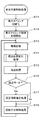
次に、HUD制御部14のCPU14aが実行する表示内容制御処理について図3を用いて説明する。表示内容制御処理は、例えばエンジンキーを差し込んで回すといった車両の始動動作によってバッテリーからCPU14aに電源が供給されることで開始する。
Next, display content control processing executed by the
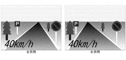
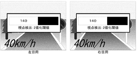
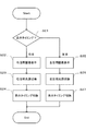
HUD制御部14は、最初に、表示タイミングを初期化する(ステップS11)。例えば、表示タイミングを右目に初期化する。そして、後述する表示タイミング制御処理の周期的な呼び出しを開始する(ステップS12)。次に、撮像部11の出力画像を取り込む撮像処理を実行する(ステップS13)。その後、取り込んだ画像に対して後述の視点位置検出処理を実行することにより、運転者2の視点位置と、それに対して最適なミラー13dの駆動角度を得る(ステップS14)。さらに、運転者2の視点位置に基づいて右目用と左目用の画像を生成する(ステップS15)。図4は、右目用画像と左目用画像の一例を示すものであり、図4においては前方の道路や標識、案内板などの道路情報と車速情報とを含む。HUD制御部14は、ROM14b内に予め記憶された例えば道路データ、標識、案内表示板といった道路情報等の3次元データから、運転者2の視点位置に基づいて運転者2の右目から見た場合の2次元データである右目用画像と、左目からみた場合の2次元データである左目用画像とを生成する。これにより、画像として道路情報などの運転者2の視点位置によって見え方が変化する情報を表示する場合に背景と表示画像とのズレによって生じる運転者2の違和感を低減することができ、運転者2に伝えたい情報を正確に伝達することが可能となる。次の条件分岐において、設定モードであるか否かの情報を車両制御システム部15から取得し(ステップS16)、設定モードである場合は(ステップS16;Yes)、後述の設定情報を描画する(ステップS17)。図5は設定情報を含む右目用画像と左目用画像の一例を示すものであり、設定情報として視点位置検出処理における2値化閾値が表示される。最後に、運転者2の視点位置に対する最適なミラー13dの駆動角度に基づいて、ミラー駆動部13eに対して制御信号を出力する(ステップS18)。その後は、ステップS13に戻り、以降電源がオフになるまで前述の処理を反復実行する。
First, the
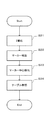
次に、HUD制御部14のCPU14aが実行する表示タイミング制御処理について図6を用いて説明する。表示タイミング制御処理は、右目用画像と左目用画像を所定の時間間隔で交互に表示させることにより運転者2に画像を立体的に視認させる処理であり、前述の表示内容制御処理においてTdミリ秒の時間間隔で周期的に呼び出される(例えばTd=33)。
Next, display timing control processing executed by the
HUD制御部14は、最初に、表示タイミングの判定を行う(ステップS21)。表示タイミングが右目である場合(ステップS21;右目)、表示パネル13bに対する右目用画像の表示更新を行う(ステップS22)。ここで表示される表示パネル13bに表示される画像はステップS15で生成された右目用画像である。次に、右目用の光源3aが点灯するように点灯させる光源3aを切換える(ステップS23)。そして、次回の表示タイミングを左目に切換え(ステップS24)、処理を終了する。また、表示タイミングが左目である場合(ステップS21;左目)、表示パネル13bに対する左目用画像の表示更新を行う(ステップS25)。ここで表示される表示パネル13bに表示される画像はステップS15で生成された左目用画像である。次に、左目用の光源3aが点灯するように点灯させる光源3aの切換えを行う(ステップS26)。そして、次回の表示タイミングを右目に切換え(ステップS27)、処理を終了する。
First, the
次に、HUD制御部14のCPU14aが前述の表示内容制御処理において実行する視点位置検出処理について図7及び図8を用いて説明する。
Next, viewpoint position detection processing executed by the
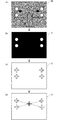
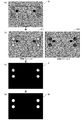
HUD制御部14は、最初に、撮像部11にて撮像したマーカー付き眼鏡12を装着した運転者2の画像B(図8(a)参照)に対して、公知の画像処理技術である2値化処理を行う(ステップS31)。この処理によって、発光マーカー12aを示す2値画像Cが得られる(図8(b)参照)。次に、2値画像C中の各発光マーカー12aの位置を、これもまた公知の画像処理技術であるラベリング処理により検出する(ステップS32、図8(c)参照)。次に、これら発光マーカー12aの位置の重心を求め(図8(d)参照)、この重心を画像B上の視点位置(xi,yi)とする(ステップS33)。最後に、視点位置のx座標xiに基づいて、図9示す画像B上の視点位置のx座標xiとミラー13dの駆動角度θiの対応関係を記述したテーブルを参照して、ミラー13dの駆動角度θiを得る(ステップS34)。HUD制御部14は、前記表示内容制御処理において、この視点位置(xi,yi)に基づき右目用画像及び左目用画像を生成して描画処理を行い、また、ミラー13dの駆動角度θiに基づき前記投影方向制御処理でミラー13dの角度制御を行う。
First, the
なお、前記視点位置検出処理において、図10(a)〜(c)に示すような設定表示をHUD13に表示させてもよい。図10(a)は、運転者2の視点位置を+印で運転者2の顔を撮像した画像Bに描画した設定表示の例である。かかる表示によれば、検出可能領域を確認することができる。図10(b)は、視点位置検出結果を画像Bに描画した設定表示の例である。かかる表示によっても、前述の設定表示例と同様に検出可能領域を確認することができる。図10(c)は、設定情報(図中では2値化閾値)を画像Bに描画した設定表示の例である。かかる表示によれば、前記視点位置検出処理における2値化閾値を始めとするパラメータを調整することができる。
In the viewpoint position detection process, a setting display as shown in FIGS. 10A to 10C may be displayed on the
以上のように、本実施形態に係る車載立体表示装置1は、1つ以上の発光マーカー12aを備え運転者2の頭部に装着可能であるマーカー付き眼鏡12と、運転者2を撮像する撮像部11と、撮像部11が撮像した運転者2の画像から運転者2の視点位置を検出するHUD制御部14と、を備え、HUD制御部14は、撮像部11が撮像した運転者2の画像B上の発光マーカー12aの位置を検出し、発光マーカー12aの位置に基づいて運転者2の視点位置を検出する。そして、検出された視点位置に基づいて右目用画像及び左目用画像を生成し、また、運転者2の視点位置に対応するようにミラー13dの回転角を制御する。このように運転者2の視点位置を検出する視点位置検出方法により、HUD制御部14は画像上で他の部分と輝度の差が大きい発光マーカー12aを割り出すことができれば良いため、運転者の顔から目を割り出す場合と比較して実装コストの低い画像処理で視点位置を検出することができ、また、明るさが常に変動する環境下でも安定して運転者2の視点位置を検出することが可能となる。
As described above, the in-vehicle
(第2実施形態)
図11は、本発明の第2実施形態に係る車載立体表示装置1の概略構成を示す図である。第2実施形態に係る車載立体表示装置1の構成は、発光マーカー制御部16を付加し、発光マーカー制御部16の出力信号に従ってマーカー付き眼鏡12の発光マーカー12aを点滅させる点を除いては第1実施形態と同様である。
(Second Embodiment)
FIG. 11 is a diagram showing a schematic configuration of the in-vehicle
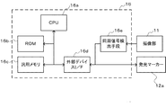
図12に、発光マーカー制御部16のハードウェア構成の一例を示す。発光マーカー制御部16は、いわゆるマイクロコンピュータから構成され、CPU16aと、ROM16bと、汎用メモリ16cと、外部デバイスI/F16dと、同期信号検出手段16eと、を備える。CPU16aは、ROM16bに予め記憶された前述した処理の所定プログラムを読み出し及び実行し、演算結果等を汎用メモリ16c内に一時的に記憶させるものである。また、同期信号検出手段16eは、撮像部11と外部デバイスI/F16dを介して接続され、撮像部11が出力する公知のインターレース方式のビデオ信号に含まれる垂直同期信号と画像信号である奇数/偶数フィールド信号とを検出する。また、発光マーカー12aは、外部デバイスI/F16d介して発光マーカー制御部16の各部に接続されている。
FIG. 12 shows an example of the hardware configuration of the light emitting
次に、発光マーカー制御部16のCPU16aが実行するマーカー点滅制御処理について図13及び図14を用いて説明する。マーカー点滅制御処理は、例えばエンジンキーを差し込んで回すといった車両の始動動作によってバッテリーからCPU16aに電源が供給されることで開始する。
Next, the marker blinking control process executed by the
発光マーカー制御部16は、最初に、同期信号検出手段16eによって垂直同期信号(図14(a))の波形の立下りを検出する(ステップS41)。それと同時に、奇数/偶数フィールド信号(図14(b))が奇数フィールドであることを示した場合(ステップS41;Yes)、タイマを初期化し時刻を0にリセットしてからリスタートする。次に、時刻tがTON≦t≦TOFFである場合(ステップS42;Yes)は、マーカー点滅制御信号としてマーカーON信号(図14(c))を出力して発光マーカー12aを点灯させる。また、時刻tがTON≦t≦TOFFでない場合は(ステップS42;No)、マーカー点滅制御信号としてマーカーOFF信号(図14(c))を出力して発光マーカー12aを消灯する。したがって、発光マーカー12a、前述のマーカーON信号とマーカーOFF信号を一定間隔で交互に入力することによって点灯と非点灯を繰り返す。すなわち、TONとTOFFとを制御することによって、撮像部11が奇数フィールドを撮像している期間のみ発光マーカー12aを点灯させる。
First, the light emission
次に、HUD制御部14のCPU14aが表示内容制御処理で実行する視点位置検出処理について図15を用いて説明する。なお、本実施形態における表示内容制御処理は、視点位置検出処理を除いては前述の第1実施形態と同様である。
Next, viewpoint position detection processing executed by the
HUD制御部14は、撮像部11が出力するビデオ信号に含まれる奇数/偶数フィールド信号からインターレース方式の画像D(図16(a))を入力すると、最初に、奇数フィールドと偶数フィールドの分離を行い、奇数フィールドの画像E1と偶数フィールドの画像E2と(図16(b))を得る(ステップS51)。なお、奇数フィールドの画像E1は奇数フィールドの各ラインの間に新たなラインを補間した画像であり、偶数フィールドの画像E2は偶数フィールドの各ラインの間に新たなラインを補間した画像である。次に、奇数フィールドの画像E1と偶数フィールドの画像E2について、公知の画像処理技術である絶対値差分を取り、差分画像F(図16(c))を得る(ステップS52)。その後、差分画像Fを公知の画像処理技術である2値化処理によって2値画像G(図16(d))に変換する(ステップS53)。そして、前述の第1実施形態のステップS32とステップS33と同様に発光マーカー12aの位置を検出し(ステップS54)、発光マーカー12aの位置の重心を求めて、この重心を画像D上の運転者2の視点位置(xi,yi)とする(ステップS55)。そして、前述の第1実施形態のステップS34と同様にして画像D上の視点位置のx座標xiとミラー13dの駆動角度θiの対応関係を記述したテーブルを参照して、ミラー13dの駆動角度θiを得る(ステップS56)。
When the interlaced image D (FIG. 16 (a)) is input from the odd / even field signal included in the video signal output from the
以上のように、本実施形態に係る車載立体表示装置1は、撮像部11から垂直同期信号と垂直同期信号に同期する奇数/偶数フィールド信号とを含むビデオ信号を入力し、垂直同期信号に基づいて発光マーカー12aを点滅させる発光マーカー制御部16を備えるものである。HUD制御部14は、撮像部11が撮像した運転者2の画像D上の発光マーカー12aの位置を検出し、発光マーカー12aの位置に基づいて運転者2の視点位置を検出する。そして、検出された視点位置に基づいて右目用画像及び左目用画像を生成し、また、運転者2の視点位置に対応するようにミラー13dの回転角を制御する。このように運転者2の視点位置を検出する視点位置検出方法により、HUD制御部14は奇数フィールドと偶数フィールドとにおける発光マーカー12aの画素の輝度が異なることを利用して発光マーカー12aを割り出すことができるため、運転者の顔から目を割り出す場合と比較して実装コストの低い画像処理で視点位置を検出することができ、また、明るさが常に変動する環境下でも安定して運転者2の視点位置を検出することが可能となる。
As described above, the in-vehicle
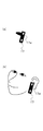
なお、本発明は、上記の実施形態に限定されず、種々の変形及び応用が可能である。本発明の視点位置検出装置及び視点位置検出方法は、車載立体表示装置に限らず他の立体表示装置に適用してもよい。また、立体表示装置は、右目用の画像と左目用の画像を交互に表示させる方式に限定されず、立体的に視認可能な立体画像を表示する画像表示部と、検出された対象者の視点位置に基づいて立体画像を生成する画像表示制御部と、を備える立体表示装置であれば本発明の視点位置検出装置及び視点位置検出方法を適用して同様の効果を得ることができる。また、第1及び第2実施形態では、発光マーカー12aはマーカー付き眼鏡12に備えられていたが、本発明のマーカー部は対象者の頭部に装着可能な形態であれば眼鏡に限定されない。図17に、イヤホンにマイクが一体化されたヘッドセット17をマーカー部とした例を示す。ヘッドセット17は,発光マーカー17aを備えるものである。発光マーカー17aは第1実施形態に適用して常時点灯させてもよく、第2実施形態に適用して点滅させてもよい。
In addition, this invention is not limited to said embodiment, A various deformation | transformation and application are possible. The viewpoint position detection apparatus and viewpoint position detection method of the present invention may be applied not only to the in-vehicle stereoscopic display apparatus but also to other stereoscopic display apparatuses. The stereoscopic display device is not limited to a method of alternately displaying a right-eye image and a left-eye image, and an image display unit that displays a stereoscopically viewable stereoscopic image, and the detected viewpoint of the target person If the stereoscopic display device includes an image display control unit that generates a stereoscopic image based on the position, the same effect can be obtained by applying the viewpoint position detection device and viewpoint position detection method of the present invention. Moreover, in 1st and 2nd embodiment, although the
1 車載立体表示装置
11 撮像部
12 マーカー付き眼鏡
12a 発光マーカー
13 ヘッドアップディスプレイ(HUD)
13a 光源
13b 表示パネル
13c 結像レンズ
13d ミラー
13e ミラー駆動部
14 HUD制御部
15 車両制御システム部
16 発光マーカー制御部
17 ヘッドセット
17a 発光マーカー
2 運転者
3 フロントガラス
DESCRIPTION OF
Claims (8)
前記視点位置検出部は、前記撮像部が撮像した前記対象者の画像上の前記発光マーカーの位置を検出し、前記発光マーカーの位置に基づいて前記対象者の視点位置を検出することを特徴とする視点位置検出装置。 A marker unit that includes one or more light-emitting markers and that can be mounted on the head of the subject; an imaging unit that images the subject; and a viewpoint position of the subject from the image of the subject captured by the imaging unit A viewpoint position detecting unit for detecting
The viewpoint position detection unit detects the position of the light emitting marker on the image of the subject captured by the imaging unit, and detects the viewpoint position of the subject based on the position of the light emitting marker. Viewpoint position detecting device.
前記撮像者は1つ以上の発光マーカーを備えるマーカー部を頭部に装着し、前記撮像部が撮像した前記対象者の画像上の前記発光マーカーの位置を検出し、前記発光マーカーの位置に基づいて前記対象者の視点位置を検出することを特徴とする視点位置検出方法。 A viewpoint position method of capturing an image of a target person with an imaging unit, and detecting the viewpoint position of the target person from the image of the target person captured by the imaging unit,
The imager wears a marker unit including one or more light emitting markers on the head, detects the position of the light emitting marker on the image of the subject imaged by the image capturing unit, and based on the position of the light emitting marker And a viewpoint position detection method, wherein the viewpoint position of the subject is detected.
請求項1または2に記載の視点位置検出装置と、前記視点位置検出装置によって検出された対象者の視点位置に基づいて前記立体画像を生成する画像表示制御部と、を備えてなることを特徴とする立体表示装置。 A stereoscopic display device including an image display unit that displays a stereoscopically viewable stereoscopic image,
The viewpoint position detection device according to claim 1, and an image display control unit that generates the stereoscopic image based on the viewpoint position of the subject detected by the viewpoint position detection device. 3D display device.
請求項1または2に記載の視点位置検出装置と、前記視点位置検出装置によって検出された対象者の視点位置に基づいて前記ヘッドアップディスプレイを制御するHUD制御部と、を備え、
前記HUD制御部は、前記視点位置検出装置によって検出された対象者の視点位置に基づいて前記右目用画像及び前記左目用画像を生成する及び/あるいは前記対象者の視点位置に対応するように前記ミラーの回転角を制御することを特徴とする立体表示装置。 A stereoscopic display device including a head-up display (HUD) that displays a stereoscopically visible stereoscopic image by reflecting it on a mirror by alternately displaying a right-eye image and a left-eye image on a display panel at predetermined time intervals. There,
The viewpoint position detection device according to claim 1, and a HUD control unit that controls the head-up display based on the viewpoint position of the subject detected by the viewpoint position detection device,
The HUD control unit generates the right-eye image and the left-eye image based on the viewpoint position of the subject detected by the viewpoint position detection device and / or corresponds to the viewpoint position of the subject. A stereoscopic display device characterized by controlling a rotation angle of a mirror.
Priority Applications (1)
| Application Number | Priority Date | Filing Date | Title |
|---|---|---|---|
| JP2011000657A JP2012141502A (en) | 2011-01-05 | 2011-01-05 | Viewpoint position detecting device, method for detecting viewpoint position, and stereographic display device |
Applications Claiming Priority (1)
| Application Number | Priority Date | Filing Date | Title |
|---|---|---|---|
| JP2011000657A JP2012141502A (en) | 2011-01-05 | 2011-01-05 | Viewpoint position detecting device, method for detecting viewpoint position, and stereographic display device |
Publications (1)
| Publication Number | Publication Date |
|---|---|
| JP2012141502A true JP2012141502A (en) | 2012-07-26 |
Family
ID=46677837
Family Applications (1)
| Application Number | Title | Priority Date | Filing Date |
|---|---|---|---|
| JP2011000657A Pending JP2012141502A (en) | 2011-01-05 | 2011-01-05 | Viewpoint position detecting device, method for detecting viewpoint position, and stereographic display device |
Country Status (1)
| Country | Link |
|---|---|
| JP (1) | JP2012141502A (en) |
Cited By (12)
| Publication number | Priority date | Publication date | Assignee | Title |
|---|---|---|---|---|
| JP2014039234A (en) * | 2012-08-20 | 2014-02-27 | Au Optronics Corp | Entertainment display system and interactive stereoscopic display method of the same |
| JP2015184671A (en) * | 2014-03-20 | 2015-10-22 | トロンクシズ テクノロジー カンパニー リミテッド | amplification display device and amplification display system |
| WO2016067729A1 (en) * | 2014-10-31 | 2016-05-06 | 株式会社ソニー・コンピュータエンタテインメント | Image generation device, image generation method and calibration method |
| JP2018092085A (en) * | 2016-12-07 | 2018-06-14 | 京セラ株式会社 | Light source device, display device, and moving body |
| WO2018105533A1 (en) * | 2016-12-07 | 2018-06-14 | 京セラ株式会社 | Image projection device, image display device, and moving body |
| JP2018092108A (en) * | 2016-12-07 | 2018-06-14 | 京セラ株式会社 | Image projection device, image display device, and moving body |
| WO2018105534A1 (en) * | 2016-12-07 | 2018-06-14 | 京セラ株式会社 | Light source device, display device, moving body, three-dimensional projection device, three-dimensional projection system, image projection device, and image display device |
| JP2018092107A (en) * | 2016-12-07 | 2018-06-14 | 京セラ株式会社 | Image projection device, image display device, and movable body |
| WO2019021340A1 (en) * | 2017-07-24 | 2019-01-31 | 三菱電機株式会社 | Display control device, display system, and display control method |
| JP2019015823A (en) * | 2017-07-05 | 2019-01-31 | 京セラ株式会社 | Three-dimensional projector, three-dimensional projection system, and movable body |
| WO2019102731A1 (en) * | 2017-11-24 | 2019-05-31 | マクセル株式会社 | Head-up display device |
| JP2022173686A (en) * | 2021-05-10 | 2022-11-22 | トヨタ自動車株式会社 | Display control device, display device, vehicle, display control method and display control program |
-
2011
- 2011-01-05 JP JP2011000657A patent/JP2012141502A/en active Pending
Cited By (21)
| Publication number | Priority date | Publication date | Assignee | Title |
|---|---|---|---|---|
| TWI458530B (en) * | 2012-08-20 | 2014-11-01 | Au Optronics Corp | Entertainment display system and interactive stereoscopic displaying method of same |
| US9300950B2 (en) | 2012-08-20 | 2016-03-29 | Au Optronics Corporation | Entertainment displaying system and interactive stereoscopic displaying method of the same |
| JP2014039234A (en) * | 2012-08-20 | 2014-02-27 | Au Optronics Corp | Entertainment display system and interactive stereoscopic display method of the same |
| JP2015184671A (en) * | 2014-03-20 | 2015-10-22 | トロンクシズ テクノロジー カンパニー リミテッド | amplification display device and amplification display system |
| US10362297B2 (en) | 2014-10-31 | 2019-07-23 | Sony Interactive Entertainment Inc. | Image generation apparatus, image generation method, and calibration method |
| WO2016067729A1 (en) * | 2014-10-31 | 2016-05-06 | 株式会社ソニー・コンピュータエンタテインメント | Image generation device, image generation method and calibration method |
| JP2018092085A (en) * | 2016-12-07 | 2018-06-14 | 京セラ株式会社 | Light source device, display device, and moving body |
| WO2018105533A1 (en) * | 2016-12-07 | 2018-06-14 | 京セラ株式会社 | Image projection device, image display device, and moving body |
| JP2018092108A (en) * | 2016-12-07 | 2018-06-14 | 京セラ株式会社 | Image projection device, image display device, and moving body |
| WO2018105534A1 (en) * | 2016-12-07 | 2018-06-14 | 京セラ株式会社 | Light source device, display device, moving body, three-dimensional projection device, three-dimensional projection system, image projection device, and image display device |
| JP2018092107A (en) * | 2016-12-07 | 2018-06-14 | 京セラ株式会社 | Image projection device, image display device, and movable body |
| JP2019015823A (en) * | 2017-07-05 | 2019-01-31 | 京セラ株式会社 | Three-dimensional projector, three-dimensional projection system, and movable body |
| WO2019021340A1 (en) * | 2017-07-24 | 2019-01-31 | 三菱電機株式会社 | Display control device, display system, and display control method |
| JPWO2019021340A1 (en) * | 2017-07-24 | 2019-11-07 | 三菱電機株式会社 | Display control device, display system, and display control method |
| CN110915205A (en) * | 2017-07-24 | 2020-03-24 | 三菱电机株式会社 | Display control device, display system, and display control method |
| WO2019102731A1 (en) * | 2017-11-24 | 2019-05-31 | マクセル株式会社 | Head-up display device |
| JPWO2019102731A1 (en) * | 2017-11-24 | 2020-12-17 | マクセル株式会社 | Head-up display device |
| JP7053664B2 (en) | 2017-11-24 | 2022-04-12 | マクセル株式会社 | Head-up display device |
| US11709369B2 (en) | 2017-11-24 | 2023-07-25 | Maxell, Ltd. | Head up display apparatus |
| JP2022173686A (en) * | 2021-05-10 | 2022-11-22 | トヨタ自動車株式会社 | Display control device, display device, vehicle, display control method and display control program |
| JP7521480B2 (en) | 2021-05-10 | 2024-07-24 | トヨタ自動車株式会社 | DISPLAY CONTROL DEVICE, DISPLAY SYSTEM, VEHICLE, DISPLAY CONTROL METHOD, AND DISPLAY CONTROL PROGRAM |
Similar Documents
| Publication | Publication Date | Title |
|---|---|---|
| CN106537227B (en) | Display device, control method and program for display device | |
| JP4686586B2 (en) | In-vehicle display device and display method | |
| CN107850944B (en) | Method for operating data glasses in a motor vehicle and system with data glasses | |
| JP5050120B1 (en) | Stereoscopic image display device | |
| CN104509108A (en) | Image display device and image display method | |
| JP2011073496A (en) | Onboard three-dimensional display device and onboard three-dimensional display method | |
| JP2012195728A (en) | Display device, display system, and method for controlling display device | |
| JP7173042B2 (en) | head-up display device | |
| KR20150070649A (en) | Display device and display method thereof | |
| JP2015060071A (en) | Image display device, image display method, and image display program | |
| JP2011107382A (en) | Display device for vehicle | |
| JP2013148599A (en) | Display device | |
| CN202738032U (en) | Image processing apparatus | |
| JPH10105735A (en) | Input device and picture display system | |
| US8872816B2 (en) | Three-dimensional image display device and driving method thereof | |
| JP2019066562A (en) | Display, display control method, and program | |
| CN108345116A (en) | Three-dimensional head up display device and the automobile with the device | |
| JP2013024910A (en) | Optical equipment for observation | |
| JP2017102220A (en) | Image display device | |
| JP2019066564A (en) | Display, display control method, and program | |
| JP2021017064A (en) | Head-up display device | |
| JP5343157B2 (en) | Stereoscopic image display device, display method, and test pattern | |
| US11187910B2 (en) | Head-up display device for adjusting display distances of virtual images | |
| JP2019068143A (en) | Display unit, display control method and program | |
| JP6268704B2 (en) | Display device, display device control method, and program |