JP2012142099A - Secondary battery and manufacturing method thereof - Google Patents
Secondary battery and manufacturing method thereof Download PDFInfo
- Publication number
- JP2012142099A JP2012142099A JP2010292143A JP2010292143A JP2012142099A JP 2012142099 A JP2012142099 A JP 2012142099A JP 2010292143 A JP2010292143 A JP 2010292143A JP 2010292143 A JP2010292143 A JP 2010292143A JP 2012142099 A JP2012142099 A JP 2012142099A
- Authority
- JP
- Japan
- Prior art keywords
- electrode group
- secondary battery
- expansion member
- plate
- vacuum
- Prior art date
- Legal status (The legal status is an assumption and is not a legal conclusion. Google has not performed a legal analysis and makes no representation as to the accuracy of the status listed.)
- Pending
Links
Images





Classifications
-
- Y—GENERAL TAGGING OF NEW TECHNOLOGICAL DEVELOPMENTS; GENERAL TAGGING OF CROSS-SECTIONAL TECHNOLOGIES SPANNING OVER SEVERAL SECTIONS OF THE IPC; TECHNICAL SUBJECTS COVERED BY FORMER USPC CROSS-REFERENCE ART COLLECTIONS [XRACs] AND DIGESTS
- Y02—TECHNOLOGIES OR APPLICATIONS FOR MITIGATION OR ADAPTATION AGAINST CLIMATE CHANGE
- Y02E—REDUCTION OF GREENHOUSE GAS [GHG] EMISSIONS, RELATED TO ENERGY GENERATION, TRANSMISSION OR DISTRIBUTION
- Y02E60/00—Enabling technologies; Technologies with a potential or indirect contribution to GHG emissions mitigation
- Y02E60/10—Energy storage using batteries
-
- Y—GENERAL TAGGING OF NEW TECHNOLOGICAL DEVELOPMENTS; GENERAL TAGGING OF CROSS-SECTIONAL TECHNOLOGIES SPANNING OVER SEVERAL SECTIONS OF THE IPC; TECHNICAL SUBJECTS COVERED BY FORMER USPC CROSS-REFERENCE ART COLLECTIONS [XRACs] AND DIGESTS
- Y02—TECHNOLOGIES OR APPLICATIONS FOR MITIGATION OR ADAPTATION AGAINST CLIMATE CHANGE
- Y02P—CLIMATE CHANGE MITIGATION TECHNOLOGIES IN THE PRODUCTION OR PROCESSING OF GOODS
- Y02P70/00—Climate change mitigation technologies in the production process for final industrial or consumer products
- Y02P70/50—Manufacturing or production processes characterised by the final manufactured product
Landscapes
- Cell Separators (AREA)
- Secondary Cells (AREA)
Abstract
【課題】正極板と負極板とセパレータとを数十層積層した大型の電極群であっても、電極群の内部まで電解液を確実に浸透させることができる二次電池およびその製造方法を提供する。
【解決手段】電極群と該電極群が載置される外装ケースの底面との間、もしくは、電極群と蓋部材との間、の少なくとも一方に、常圧時には平坦で、真空時に膨らむ膨張部材を介装し、真空引き時に膨張部材を膨らませて電極群の中央部分を押圧して、空気が抜け難い電極群の中央部の空気を十分排出し、その後から電解液を注液する二次電池およびその製造方法とした。
【選択図】図1ADisclosed is a secondary battery capable of reliably infiltrating an electrolyte into an electrode group even in a large electrode group in which several tens of layers of a positive electrode plate, a negative electrode plate, and a separator are laminated, and a method for manufacturing the same To do.
An expansion member that is flat at normal pressure and expands at vacuum between at least one of an electrode group and a bottom surface of an outer case on which the electrode group is placed or between an electrode group and a lid member. A secondary battery in which the expansion member is inflated at the time of evacuation, presses the central part of the electrode group, sufficiently discharges air in the central part of the electrode group that is difficult to escape, and then injects the electrolyte And its manufacturing method.
[Selection] Figure 1A
Description
本発明は、二次電池に関し、特に、積層型の電極群を有する二次電池において、大型の電極群を備える二次電池であっても、電解液を効率よく確実に浸透させることが可能な二次電池およびその製造方法に関する。 The present invention relates to a secondary battery, and in particular, in a secondary battery having a stacked electrode group, an electrolyte can be efficiently and surely permeated even in a secondary battery having a large electrode group. The present invention relates to a secondary battery and a manufacturing method thereof.
近年、高エネルギー密度を有し小型軽量化が可能であることからリチウム二次電池が、携帯電話やノート型パソコン等の携帯型電子機器の電源用電池として用いられている。また、大容量化が可能であることから、電気自動車(EV)やハイブリッド電気自動車(HEV)等のモータ駆動電源や、電力貯蔵用蓄電池としても注目されてきている。 In recent years, lithium secondary batteries have been used as power source batteries for portable electronic devices such as mobile phones and notebook computers because they have a high energy density and can be reduced in size and weight. Further, since the capacity can be increased, it has been attracting attention as a motor drive power source for electric vehicles (EV) and hybrid electric vehicles (HEV), and a storage battery for power storage.
上記リチウム二次電池は、電池缶を構成する外装ケース内部に正極板と負極板とをセパレータを挟んで対向配置した電極群を収納し、電解液を充填し、複数の正極板の正極集電タブに連結される正極集電端子と、この正極集電端子と電気的に接続される正極外部端子と、複数の負極板の負極集電タブに連結される負極集電端子と、この負極集電端子と電気的に接続される負極外部端子を備えた構成とされる。 In the lithium secondary battery, an electrode group in which a positive electrode plate and a negative electrode plate are arranged opposite to each other with a separator interposed therebetween is housed in an outer case constituting a battery can, filled with an electrolyte, and positive electrode current collectors of a plurality of positive electrode plates A positive current collecting terminal coupled to the tab; a positive external terminal electrically connected to the positive current collecting terminal; a negative current collecting terminal coupled to the negative current collecting tabs of the plurality of negative electrode plates; and the negative current collecting terminal. It is set as the structure provided with the negative electrode external terminal electrically connected with an electrical terminal.
また、電極群としては、巻回型と積層型が知られている。巻回型の電極群は、正極板と負極板との間にセパレータを介装して一体に巻回した構成であり、積層型の電極群は、正極板と負極板とをセパレータを介して複数層積層した構成である。 As the electrode group, a wound type and a laminated type are known. The wound electrode group has a configuration in which a separator is interposed between a positive electrode plate and a negative electrode plate, and is integrally wound. The laminated electrode group has a positive electrode plate and a negative electrode plate interposed via a separator. It is the structure which laminated | stacked multiple layers.
積層型の電極群を備えるリチウム二次電池においては、正極板と負極板とをセパレータを介して複数層積層した電極群を外装ケースに収容し、非水電解液で充填した構成とされ、それぞれの正極板の正極集電タブに連結される正極集電端子と、この正極集電端子と電気的に接続される外部端子、および、負極板の負極集電タブに連結される負極集電端子と、この負極集電端子と電気的に接続される外部端子がそれぞれ設けられている。 In a lithium secondary battery including a stacked electrode group, an electrode group in which a plurality of layers of a positive electrode plate and a negative electrode plate are stacked via a separator is housed in an outer case and filled with a non-aqueous electrolyte, respectively. A positive current collecting terminal coupled to the positive current collecting tab of the positive electrode plate, an external terminal electrically connected to the positive current collecting terminal, and a negative current collecting terminal coupled to the negative current collecting tab of the negative electrode plate And an external terminal electrically connected to the negative electrode current collecting terminal.
この積層型の場合に大容量の二次電池を作製するためには、正極板および負極板の面積を大きくし、積層数を増加し、充填する電解液量も増加させることが必要である。そのために、表面積が大きく、厚みが厚い状態に作製される電極群の内部まで、電解液を確実に浸透させることが肝要となる。 In order to produce a secondary battery with a large capacity in the case of this stacked type, it is necessary to increase the areas of the positive electrode plate and the negative electrode plate, increase the number of stacked layers, and increase the amount of electrolyte to be filled. Therefore, it is important to ensure that the electrolytic solution penetrates into the electrode group having a large surface area and a large thickness.
従来、巻回形成された電極群および積層形成された電極群に電解液を浸透させるためには、電池缶内を真空にして電解液を注液する真空注液法が採用されている。また、高容量化につれて、活物質の高密度化、正極板と負極板とセパレータの緊迫度の上昇に伴い、低下する非水電解液注液工程の生産性向上と電池品質の向上を図るために、缶内を真空にする第一工程と、電解液に溶解し得る気体を注入する第二工程と、電解液を注入する第三工程と、さらに、一定時間減圧する第四工程とを備えた二次電池の製造方法が既に公開されている(例えば、特許文献1参照)。 Conventionally, in order to infiltrate the electrolyte solution into the wound electrode group and the stacked electrode group, a vacuum injection method in which the inside of the battery can is evacuated and the electrolyte solution is injected is employed. To increase the density of the active material and increase the tightness of the positive electrode plate, the negative electrode plate, and the separator as the capacity increases, to improve the productivity of the non-aqueous electrolyte injection process that decreases, and to improve the battery quality A first step of evacuating the inside of the can, a second step of injecting a gas that can be dissolved in the electrolytic solution, a third step of injecting the electrolytic solution, and a fourth step of reducing the pressure for a certain time. In addition, a method for manufacturing a secondary battery has already been disclosed (for example, see Patent Document 1).
正極板と負極板と電解液とを有する二次電池の容量を大きくし、電池寿命を長くするためには、発電面積を大きくし、充填する電解液の量を増量することが好ましいので、それぞれの極板の面積を大きくし、積層する層数も増加すると共に、充填する電解液量を増量する傾向にある。そうすると、積層された極板の内部(電極群の中心部)に電解液が浸透するまでの時間が長くなってしまい、電解液注液工程の生産性が低下する。 In order to increase the capacity of the secondary battery having the positive electrode plate, the negative electrode plate, and the electrolyte and to extend the battery life, it is preferable to increase the power generation area and increase the amount of the electrolyte to be filled. The area of the electrode plate is increased, the number of layers to be stacked is increased, and the amount of electrolyte solution to be filled tends to be increased. If it does so, time until electrolyte solution osmose | permeates inside the laminated | stacked electrode plate (center part of an electrode group) will become long, and productivity of an electrolyte solution injection process will fall.
電池缶内を真空にして電解液を注液することで、電極群の内部まで電解液を浸透させることは可能である。しかし、電極群が大型化すると、電極群内部の空気を完全に排気することが困難となって残留空気が発生し、電解液を充分浸透させることができなくなる問題を生じる。 It is possible to infiltrate the electrolyte into the electrode group by evacuating the battery can and injecting the electrolyte. However, when the size of the electrode group is increased, it is difficult to completely exhaust the air inside the electrode group, and residual air is generated, which causes a problem that the electrolyte cannot be sufficiently permeated.
また、特許文献1に記載された方法では、電池品質の向上を図ることができても、電解液に溶解する気体を注入するので、工程が複雑となり、余分な装置が必要となるので電解液注液コストが高くなって好ましくない。
Further, in the method described in
そのために、より簡単な方法で電解液を電極群の内部まで確実に浸透させることが好ましく、より短時間で電解液を浸透させることが可能な電池構造であり、電池の製造方法であることが好ましい。 Therefore, it is preferable that the electrolytic solution is reliably infiltrated into the electrode group by a simpler method, the battery structure is capable of infiltrating the electrolytic solution in a shorter time, and is a method for manufacturing a battery. preferable.
また、電池品質の向上を図るためには、電極群の内部まで電解液を十分浸透させることが重要であり、特に、多数(例えば、数十層)の正極板と負極板とセパレータとを積層した電極群を備える大容量の積層型の二次電池においては、安定した電池容量と電池品質を維持するために、電極群の内部まで電解液を確実に浸透させることが好ましい。 Moreover, in order to improve battery quality, it is important to sufficiently infiltrate the electrolyte into the electrode group. In particular, a large number (for example, several tens of layers) of positive electrode plates, negative electrode plates, and separators are laminated. In a large-capacity stacked secondary battery including the electrode group, it is preferable to reliably infiltrate the electrolyte into the electrode group in order to maintain stable battery capacity and battery quality.
そのために、正極板と負極板とセパレータとを数十層積層した大型の電極群であっても、電解液を比較的短時間で電極群の内部まで浸透させることができる電池構造の二次電池であることが好ましく、電解液を比較的短時間で電極群の内部まで浸透させることができる二次電池の製造方法であることが好ましい。 Therefore, even in a large electrode group in which several tens of layers of a positive electrode plate, a negative electrode plate, and a separator are stacked, a secondary battery having a battery structure that can permeate the electrolyte into the electrode group in a relatively short time It is preferable that the method is a method for manufacturing a secondary battery in which the electrolytic solution can penetrate into the electrode group in a relatively short time.
そこで本発明は、上記問題点に鑑み、正極板と負極板とセパレータとを数十層積層した大型の電極群であっても、電極群の内部まで電解液を確実に浸透させることができる二次電池およびその製造方法を提供することを目的とする。 Therefore, in view of the above problems, the present invention can reliably infiltrate the electrolyte into the electrode group even in a large electrode group in which several tens of layers of a positive electrode plate, a negative electrode plate, and a separator are laminated. It is an object of the present invention to provide a secondary battery and a manufacturing method thereof.
上記目的を達成するために本発明は、正極板と負極板とをセパレータを介して複数層積層した電極群と、この電極群を収容する外装ケースと、前記外装ケースを密閉する蓋部材とを備え、これらの外装ケースと蓋部材とで構成される電池缶の内部に電解液が注液され前記電極群の内部まで浸透して充填される二次電池であって、前記電極群の積層方向の前記外装ケースの底面と前記電極群との間、もしくは、前記電極群と前記蓋部材との間、の少なくとも一方に、常圧時には平坦で、真空時に膨らむ膨張部材を介装したことを特徴としている。 To achieve the above object, the present invention provides an electrode group obtained by laminating a plurality of layers of a positive electrode plate and a negative electrode plate with a separator interposed therebetween, an exterior case that accommodates the electrode group, and a lid member that seals the exterior case. A secondary battery in which an electrolyte is injected into a battery can constituted by the outer case and the lid member and penetrates and fills the inside of the electrode group, the stacking direction of the electrode group An expansion member that is flat during normal pressure and expands during vacuum is interposed between at least one of the bottom surface of the outer case and the electrode group, or between the electrode group and the lid member. It is said.
この構成によると、真空時に膨らむ膨張部材を介装しているので、電解液を真空注液する際に、膨張部材によって電極群を圧迫して内部に残留している空気を押し出すことができる。そのために、電極群の中央部に空気が残留せず、電極群の内部まで電解液を確実に浸透させることができる二次電池を得ることができる。 According to this structure, since the expansion member which swells at the time of vacuum is interposed, when the electrolyte solution is injected into the vacuum, the electrode group can be pressed by the expansion member and the air remaining inside can be pushed out. Therefore, it is possible to obtain a secondary battery in which air does not remain in the center portion of the electrode group and the electrolyte solution can reliably penetrate into the electrode group.
また本発明は上記構成の二次電池において、前記膨張部材は、平面視円形の袋状とされ、真空時に凸レンズ状に膨らむことを特徴としている。この構成によると、真空時に膨張部材が凸レンズ状に膨らんで、電極群の中央部分を押圧する構成となり、排気され難い中央部分の空気を押し出す作用を発揮して、電極群の中央部まで電解液を浸透させることができる。 According to the present invention, in the secondary battery configured as described above, the expansion member has a circular bag shape in plan view, and expands into a convex lens shape in a vacuum. According to this configuration, the expansion member swells in a convex lens shape in a vacuum state and presses the central portion of the electrode group, and exerts an action of pushing out air in the central portion that is difficult to be exhausted. Can penetrate.
また本発明は上記構成の二次電池において、前記膨張部材は、平面視楕円形の袋状とされ、真空時に凸レンズ状に膨らむことを特徴としている。この構成によると、電極群が長辺部と短辺部を有する矩形状であっても、中央部分が楕円状に膨らむ膨張部材を介して、電極群の中央部まで電解液を浸透させることができる。 According to the present invention, in the secondary battery having the above-described configuration, the expansion member has an oval bag shape in plan view, and expands into a convex lens shape in a vacuum. According to this configuration, even when the electrode group has a rectangular shape having a long side portion and a short side portion, the electrolyte solution can be permeated to the central portion of the electrode group through the expansion member whose central portion swells elliptically. it can.
また本発明は上記構成の二次電池において、前記膨張部材と前記電極群との間に所定の曲率で凸レンズ状に湾曲する湾曲プレートを介装したことを特徴としている。この構成によると、真空時に膨張部材が膨らむと、湾曲プレートの湾曲形状に応じて電極群を押圧して、電極群の中央部の所定領域の空気を排出することができる。 In the secondary battery having the above-described configuration, the present invention is characterized in that a curved plate that curves in a convex lens shape with a predetermined curvature is interposed between the expansion member and the electrode group. According to this configuration, when the expansion member expands during the vacuum, the electrode group can be pressed according to the curved shape of the curved plate, and air in a predetermined area at the center of the electrode group can be discharged.
また本発明は上記構成の二次電池において、前記膨張部材と前記電極群との間に、前記膨張部材の中央部で変位自在に連結された二枚のプレートからなる押圧プレートを介装したことを特徴としている。この構成によると、真空時に凸レンズ状に膨らむ膨張部材により、二枚のプレートからなる押圧プレートの連結部が押し上げられるので、電極群の中央部を確実に押圧して空気を残らず排出することができる。 According to the present invention, in the secondary battery having the above-described configuration, a pressing plate composed of two plates connected to be displaceable at a central portion of the expansion member is interposed between the expansion member and the electrode group. It is characterized by. According to this configuration, since the connecting portion of the pressing plate composed of the two plates is pushed up by the expansion member that swells in a convex lens shape in a vacuum, the central portion of the electrode group can be reliably pressed and air can be discharged without remaining. it can.
また本発明は、正極板と負極板とをセパレータを介して複数層積層した電極群と、この電極群を収容する外装ケースと、前記外装ケースを密閉する蓋部材とを備え、これらの外装ケースと蓋部材とで構成される電池缶の内部に電解液が注液され前記電極群の内部まで浸透して充填される二次電池の製造方法であって、前記電極群の積層方向の前記外装ケースの底面と前記電極群との間、もしくは、前記電極群と前記蓋部材との間、の少なくとも一方に、常圧時には平坦で、真空時に膨らむ膨張部材を介装し、前記電池缶の内部を真空にして前記膨張部材を所定量膨らませた後で前記電解液を注入することを特徴としている。 Further, the present invention includes an electrode group in which a plurality of layers of a positive electrode plate and a negative electrode plate are laminated via a separator, an exterior case that accommodates the electrode group, and a lid member that seals the exterior case. And a lid member. A method of manufacturing a secondary battery in which an electrolyte is injected into a battery can constituted by infiltrating and filling the inside of the electrode group, and the exterior in the stacking direction of the electrode group At least one of the bottom surface of the case and the electrode group or between the electrode group and the lid member is provided with an expansion member that is flat at normal pressure and swells when vacuumed. The electrolytic solution is injected after the expansion member is expanded by a predetermined amount by vacuuming.
この構成によると、真空時に膨らむので、電極群を圧迫して内部に残留している空気を残らず押し出すことができる。そのために、電極群の内部の空気を十分排気した後で電解液を注液する構成となって、電極群の内部まで電解液を確実に浸透させることができる二次電池の製造方法となる。 According to this structure, since it swells at the time of a vacuum, it can press out an electrode group and can push out all the air remaining inside. Therefore, it becomes the structure which injects electrolyte solution after fully exhausting the air inside an electrode group, and becomes a manufacturing method of the secondary battery which can infiltrate electrolyte solution to the inside of an electrode group reliably.
また本発明は上記構成の二次電池の製造方法において、前記外装ケースに前記電極群を収容して前記蓋部材を装着して密閉された電池缶を作製する第一工程と、前記電池缶内を減圧して前記膨張体を膨らます第二工程と、前記電池缶内に電解液を注液する第三工程とを備えることを特徴としている。この構成によると、電池缶内を減圧して膨張体を膨らます第二工程を備えているので、真空時に電極群の中央部を押圧して内部の空気を効果的に押し出すことができ、電解液を電極群内部まで浸透させるための準備を確実に実行することができる。 Further, the present invention provides a method for manufacturing a secondary battery having the above-described structure, wherein the electrode can be accommodated in the outer case and the lid member is attached to produce a sealed battery can; And a third step of injecting an electrolyte into the battery can. According to this configuration, since the second step of expanding the expansion body by decompressing the inside of the battery can is provided, it is possible to effectively push out the air inside by pressing the center part of the electrode group during vacuum. It is possible to reliably execute the preparation for penetrating the electrode group into the electrode group.
また本発明は上記構成の二次電池の製造方法において、前記膨張部材は、平面視円形もしくは平面視楕円形の袋状とされ、真空時に凸レンズ状に膨らむことを特徴としている。この構成によると、真空時に凸レンズ状に膨らんで、電極群の中央部分を押圧する構成となり、排気され難い中央部分の空気を押し出す作用を発揮して、電極群の中央部まで電解液を確実に浸透させることができる。 According to the present invention, in the method of manufacturing a secondary battery having the above-described configuration, the expansion member is formed into a bag shape having a circular shape in plan view or an elliptical shape in plan view, and is expanded into a convex lens shape in a vacuum. According to this configuration, it becomes a configuration that swells in a convex lens shape in a vacuum and presses the central part of the electrode group, exerts an action of pushing out the air of the central part that is difficult to be exhausted, and ensures the electrolyte solution to the central part of the electrode group Can penetrate.
また本発明は上記構成の二次電池の製造方法において、前記膨張部材と前記電極群との間に所定の曲率で凸レンズ状に湾曲する湾曲プレートを介装したことを特徴としている。この構成によると、真空時に膨張部材を膨らませて、湾曲プレートを湾曲させることで電極群の所定領域を押圧して、空気が抜け難い電極群の中央部の空気を十分排出することができる。 According to the present invention, in the method for manufacturing a secondary battery having the above-described configuration, a curved plate that is curved in a convex lens shape with a predetermined curvature is interposed between the expansion member and the electrode group. According to this configuration, the expansion member is inflated at the time of vacuum, and the curved plate is bent to press the predetermined region of the electrode group, so that the air in the central portion of the electrode group that is difficult to remove air can be sufficiently discharged.
また本発明は上記構成の二次電池の製造方法において、前記膨張部材と前記電極群との間に、前記膨張部材の中央部で変位自在に連結された二枚のプレートからなる押圧プレートを介装したことを特徴としている。この構成によると、真空時に凸レンズ状に膨らむ膨張部材により、二枚のプレートからなる押圧プレートの連結部が押し上げられるので、電極群の中央部分を確実に押圧して空気を残らず排出することができて、電解液を電極群の内部まで十分浸透させることができる。 According to the present invention, in the method for manufacturing a secondary battery having the above-described configuration, a pressing plate including two plates movably connected at a central portion of the expansion member is provided between the expansion member and the electrode group. It is characterized by wearing. According to this configuration, since the connecting portion of the pressing plate composed of the two plates is pushed up by the expansion member that swells in a convex lens shape in a vacuum, the central portion of the electrode group can be reliably pressed and air can be discharged without remaining. Thus, the electrolyte can be sufficiently penetrated into the electrode group.
本発明によれば、電極群と外装ケースの底面との間、もしくは、電極群と蓋部材の間、の少なくとも一方に、常圧時には平坦で、真空時に膨らむ膨張部材を介装したので、膨張部材によって電極群を圧迫して内部に残留している空気を押し出すことができる。そのために、正極板と負極板とセパレータとを数十層積層した大型の電極群であっても、電極群の内部まで電解液を確実に浸透させることができる二次電池およびその製造方法を得ることができる。 According to the present invention, an expansion member that is flat at normal pressure and expands during vacuum is interposed between at least one of the electrode group and the bottom surface of the outer case or between the electrode group and the lid member. The electrode can be pressed by the member to push out the air remaining inside. Therefore, even in a large electrode group in which several tens of layers of a positive electrode plate, a negative electrode plate, and a separator are stacked, a secondary battery that can reliably infiltrate the electrolyte into the electrode group and a method for manufacturing the same are obtained. be able to.
以下に本発明の実施形態を図面を参照して説明する。また、同一構成部材については同一の符号を用い、詳細な説明は適宜省略する。 Embodiments of the present invention will be described below with reference to the drawings. Moreover, the same code | symbol is used about the same structural member, and detailed description is abbreviate | omitted suitably.
本発明に係る二次電池としてリチウム二次電池について説明する。例えば、図1Aに示す本実施形態に係る二次電池RB1は、積層型のリチウム二次電池であって、正極板と負極板とをセパレータを介して複数層積層した積層型の電極群1を備えている。また、極板の面積を大きくし、積層数を増やすことで比較的大容量の二次電池となり、電気自動車用蓄電池や電力貯蔵用蓄電池などに適用可能なものである。
A lithium secondary battery will be described as the secondary battery according to the present invention. For example, the secondary battery RB1 according to this embodiment shown in FIG. 1A is a stacked lithium secondary battery, and includes a stacked
次に、積層型のリチウム二次電池RBと電極群1の具体的な構成について、図6〜図9を用いて説明する。
Next, specific configurations of the stacked lithium secondary battery RB and the
図6に示すように、積層型のリチウム二次電池RBは平面視矩形とされ、それぞれが矩形とされる正極板と負極板とセパレータとを積層した電極群1を備えている。また、底部11aと側部11b〜11eを備えて箱型とされる外装ケース11と蓋部材12とから構成される電池缶10に収容して、外装ケース11の側面(例えば、側部11b、11cの対向する二側面)に設ける外部端子11fから充放電を行う構成としている。
As shown in FIG. 6, the stacked lithium secondary battery RB has a rectangular shape in plan view, and includes an
電極群1は、正極板と負極板とをセパレータを介して複数層積層した構成であって、図7に示すように、正極集電体2b(例えば、アルミニウム箔)の両面に正極活物質からなる正極活物質層2aが形成された正極板2と、負極集電体3b(例えば、銅箔)の両面に負極活物質からなる負極活物質層3aが形成された負極板3とがセパレータ4を介して積層されている。
The
セパレータ4により、正極板2と負極板3との絶縁が図られているが、外装ケース11に充填される電解液を介して正極板2と負極板3との間でリチウムイオンの移動が可能となっている。
Although the separator 4 insulates the
ここで、正極板2の正極活物質としては、リチウムが含有された酸化物(LiCoO2,LiNiO2,LiFeO2,LiMnO2,LiMn2O4など)や、その酸化物の遷移金属の一部を他の金属元素で置換した化合物などが挙げられる。なかでも、通常の使用において、正極板2が保有するリチウムの80%以上を電池反応に利用し得るものを正極活物質として用いれば、過充電などの事故に対する安全性を高めることができる。
Here, as the positive electrode active material of the
また、負極板3の負極活物質としては、リチウムが含有された物質やリチウムの挿入/離脱が可能な物質が用いられる。特に、高いエネルギー密度を持たせるためには、リチウムの挿入/離脱電位が金属リチウムの析出/溶解電位に近いものを用いるのが好ましい。その典型例は、粒子状(鱗片状、塊状、繊維状、ウィスカー状、球状および粉砕粒子状など)の天然黒鉛もしくは人造黒鉛である。
Further, as the negative electrode active material of the
なお、正極板2の正極活物質に加えて、また、負極板3の負極活物質に加えて、導電材、増粘材および結着材などが含有されていてもよい。導電材は、正極板2や負極板3の電池性能に悪影響を及ぼさない電子伝導性材料であれば特に限定されず、例えば、カーボンブラック、アセチレンブラック、ケッチェンブラック、グラファイト(天然黒鉛、人造黒鉛)、炭素繊維などの炭素質材料や導電性金属酸化物などを用いることができる。
In addition to the positive electrode active material of the
増粘材としては、例えば、ポリエチレングリコール類、セルロース類、ポリアクリルアミド類、ポリN−ビニルアミド類、ポリN−ビニルピロリドン類などを用いることができる。結着材は、活物質粒子および導電材粒子を繋ぎとめる役割を果たすものであり、ポリフッ化ビニリデン、ポリビニルピリジン、ポリテトラフルオロエチレンなどのフッ素系ポリマーや、ポリエチレン、ポリプロピレンなどのポリオレフィン系ポリマーや、スチレンブタジエンゴムなどを用いることができる。 As the thickener, for example, polyethylene glycols, celluloses, polyacrylamides, poly N-vinyl amides, poly N-vinyl pyrrolidones and the like can be used. The binder serves to hold the active material particles and the conductive material particles together, and includes a fluorine-based polymer such as polyvinylidene fluoride, polyvinyl pyridine and polytetrafluoroethylene, a polyolefin polymer such as polyethylene and polypropylene, Styrene butadiene rubber or the like can be used.
また、セパレータ4としては、微多孔性の高分子フィルムを用いることが好ましい。具体的には、ナイロン、セルロースアセテート、ニトロセルロース、ポリスルホン、ポリアクリロニトリル、ポリフッ化ビニリデン、ポリプロピレン、ポリエチレン、ポリブテンなどのポリオレフィン高分子からなるフィルムが使用可能である。 Moreover, as the separator 4, it is preferable to use a microporous polymer film. Specifically, films made of a polyolefin polymer such as nylon, cellulose acetate, nitrocellulose, polysulfone, polyacrylonitrile, polyvinylidene fluoride, polypropylene, polyethylene, polybutene can be used.
また、電解液としては、有機電解液を用いることが好ましい。具体的には、有機電解液の有機溶媒として、エチレンカーボネート、プロピレンカーボネート、ブチレンカーボネート、ジエチルカーボネート、ジメチルカーボネート、メチルエチルカーボネート、γ―ブチロラクトンなどのエステル類、テトラヒドロフラン、2−メチルテトラヒドロフラン、ジオキサン、ジオキソラン、ジエチルエーテル、ジメトキシエタン、ジエトキシエタン、メトキシエトキシエタンなどのエーテル類、さらに、ジメチルスルホキシド、スルホラン、メチルスルホラン、アセトニトリル、ギ酸メチル、酢酸メチルなどが使用可能である。なお、これらの有機溶媒は、単独で使用してもよいし、2種類以上を混合して使用してもよい。 Moreover, it is preferable to use an organic electrolytic solution as the electrolytic solution. Specifically, as an organic solvent of the organic electrolyte, esters such as ethylene carbonate, propylene carbonate, butylene carbonate, diethyl carbonate, dimethyl carbonate, methyl ethyl carbonate, and γ-butyrolactone, tetrahydrofuran, 2-methyltetrahydrofuran, dioxane, dioxolane , Diethyl ether, dimethoxyethane, diethoxyethane, methoxyethoxyethane, and other ethers, dimethyl sulfoxide, sulfolane, methyl sulfolane, acetonitrile, methyl formate, and methyl acetate can be used. These organic solvents may be used alone or in combination of two or more.
さらに、有機溶媒には電解質塩が含まれていてもよい。この電解質塩としては、過塩素酸リチウム(LiClO4)、ホウフッ化リチウム、六フッ化リン酸リチウム、トリフルオロメタンスルホン酸(LiCF3SO3)、フッ化リチウム、塩化リチウム、臭化リチウム、ヨウ化リチウムおよび四塩化アルミン酸リチウムなどのリチウム塩が挙げられる。なお、これらの電解質塩は、単独で使用してもよいし、2種類以上を混合して使用してもよい。 Further, the organic solvent may contain an electrolyte salt. Examples of the electrolyte salt include lithium perchlorate (LiClO 4 ), lithium borofluoride, lithium hexafluorophosphate, trifluoromethanesulfonic acid (LiCF 3 SO 3 ), lithium fluoride, lithium chloride, lithium bromide, and iodide. And lithium salts such as lithium and lithium tetrachloroaluminate. In addition, these electrolyte salts may be used independently and may be used in mixture of 2 or more types.
電解質塩の濃度は特に限定されないが、約0.5〜約2.5mol/Lであれば好ましく、約1.0〜2.2mol/Lであればより好ましい。なお、電解質塩の濃度が約0.5mol/L未満の場合には、電解液中においてキャリア濃度が低くなり、電解液の抵抗が高くなる虞がある。一方、電解質塩の濃度が約2.5mol/Lよりも高い場合には、塩自体の解離度が低くなり、電解液中のキャリア濃度が上がらない虞がある。 The concentration of the electrolyte salt is not particularly limited, but is preferably about 0.5 to about 2.5 mol / L, and more preferably about 1.0 to 2.2 mol / L. When the concentration of the electrolyte salt is less than about 0.5 mol / L, the carrier concentration in the electrolytic solution is lowered, and the resistance of the electrolytic solution may be increased. On the other hand, when the concentration of the electrolyte salt is higher than about 2.5 mol / L, the dissociation degree of the salt itself is lowered, and there is a possibility that the carrier concentration in the electrolytic solution does not increase.
電池缶10は、外装ケース11と蓋部材12とを備え、鉄、ニッケルメッキされた鉄、ステンレススチール、およびアルミニウムなどからなる。また、本実施形態では、図8に示すように、電池缶10は、外装ケース11と蓋部材12とが組み合わされたときに、外形形状が実質的に扁平角型形状となるように形成されている。
The battery can 10 includes an
外装ケース11は、略長方形状の底面を持つ底部11aと、この底部11aから立設した4面の側部11b〜11eを有する箱型状とされ、この箱型状内部に電極群1を収容する。電極群1は、正極板の集電タブに連結される正極集電端子と、負極板の集電タブに連結される負極集電端子を備え、これらの集電タブと電気的に接続される外部端子11fが外装ケース11の側部にそれぞれ設けられている。外部端子11fは、例えば、対向する二側部11b、11cの二箇所に設けられる。また、10aは注液口であって、ここから電解液を注液する。
The
外装ケース11に電極群1を収容し、それぞれの集電端子を外部端子に接続した後、もしくは、電極群1の集電端子にそれぞれの外部端子を接続し手外装ケース11に収容し、外部端子を外装ケースの所定部位に固着した後、蓋部材12を外装ケース11の開口縁に固定する。すると、外装ケース11の底部11aと蓋部材12との間に電極群1が挟持され、電池缶10の内部において電極群1が保持される。なお、外装ケース11に対する蓋部材12の固定は、例えば、レーザ溶接などによってなされる。また、集電端子と外部端子との接続は、超音波溶接やレーザ溶接、抵抗溶接などの溶接以外に導電性接着剤などを用いて行うこともできる。
After the
上記したように、本実施形態に係る積層型の二次電池は、正極板2と負極板3とをセパレータ4を介して複数層積層した電極群1と、この電極群1を収容し電解液が充填される外装ケース11と、外装ケース11に設ける外部端子11fと、正負の極板と外部端子11fとを電気的に接続する正負の集電端子と、外装ケース11に装着される蓋部材12と、を備えた構成である。
As described above, the stacked secondary battery according to the present embodiment includes an
外装ケース11に収容された電極群1は、例えば、図9に示すように、正極集電体2bの両面に正極活物質層2aが形成された正極板2と、負極集電体3bの両面に負極活物質層3aが形成された負極板3とがセパレータ4を介して積層され、さらに両端面にセパレータ4を配設している。また、両端面のセパレータ4に替えて、このセパレータ4と同じ材質の樹脂フィルムを巻回して、電極群1を絶縁性を有する樹脂フィルムで被覆する構成としてもよい。いずれにしても、積層電極群1の上面は、電解液浸透性および絶縁性を有する部材が積層される構成となる。そのために、この面に直接蓋部材12を当接させることができ、蓋部材を介して所定の圧で押さえ付けることも可能である。
For example, as shown in FIG. 9, the
また、所定の電池容量を発揮するためには、電極群1の内部まで電解液が十分浸透していることが肝要であるので、電極群1が大型化して厚みが厚くなると、二次電池の製造時に、電極群1内部に空気が残留しないように十分真空引きすることが求められる。
Further, in order to exert a predetermined battery capacity, it is important that the electrolyte solution penetrates sufficiently into the inside of the
外装ケース11に電極群1を収容し、蓋部材12を装着して密閉した電池缶10を真空引きすることで、電極群1内部の空気を排出することは可能である。しかし、電極群1のサイズが大きくなると、真空度を上げ、真空引きの時間を長くしても、電極群1内部に残留する空気を完全に排出することは困難となる。
It is possible to discharge the air inside the
そこで、本実施形態では、正極板と負極板とセパレータとを数十層積層した大型の電極群であっても、電極群内部の空気を積極的に押し出す膨張部材を介装する構成とし、積層体中央部の抜け難い空気を効率よく押し出して、電解液染み込み性を向上させて、電極群の内部まで電解液を確実に浸透させることが可能となる二次電池およびその製造方法としたものである。次に、具体的な二次電池の実施形態について、図1〜図3を用いて説明する。 Therefore, in the present embodiment, even in a large electrode group in which several tens of layers of a positive electrode plate, a negative electrode plate, and a separator are stacked, an expansion member that positively pushes out air inside the electrode group is interposed and stacked. It is a secondary battery that efficiently extrudes air that is difficult to escape from the center of the body, improves the penetration of the electrolyte, and allows the electrolyte to penetrate into the inside of the electrode group, and its manufacturing method. is there. Next, specific embodiments of the secondary battery will be described with reference to FIGS.
図1Aの断面模式図に示す第一実施形態の二次電池RB1は、外装ケース11内に収容する電極群1と該電極群1が載置される外装ケース11の底面との間に、常圧時には平坦で、真空時に膨らむ膨張部材13を介装した構成である。また、真空引きしたときに、膨張部材13が膨らんでいる状態を模式的に示している。
The secondary battery RB1 of the first embodiment shown in the schematic cross-sectional view of FIG. 1A is always between the
また、外装ケース11に蓋部材12を取り付けて、電池缶10を構成している。この蓋部材12は図示するように平板状であってもよく、また、電極群1の上面に当接する部分が凸状に突出して外装ケース11に嵌まり込む皿型状であってもよく、電池缶10のサイズと電極群1の厚みにより、その形状が適宜選択される。いずれにしても、蓋部材12を介して、電極群1が備える正極板と負極板とが適度に密着するように構成することができる。
Further, the battery can 10 is configured by attaching the
また、図1Bに示す変形例の二次電池RB1aのように、電極群1と蓋部材12との間に、膨張部材13を介装する構成としてもよい。いずれにしても、電極群1の積層方向の外装ケース11の底面と電極群1との間、もしくは、電極群1と蓋部材12との間、の少なくとも一方に、常圧時には平坦で、真空時に膨らむ膨張部材13を介装していることが好ましい。
Moreover, it is good also as a structure which interposes the
上記したように本実施形態では、真空時に膨らむ膨張部材13を介装しているので、電解液を真空注液する際に、膨張部材13によって電極群1を圧迫して内部に残留している空気を押し出すことができる。そのために、電極群1の内部に空気が残留せず、電解液染み込み性が向上して、厚みの厚い電極群1の中央部まで電解液を確実に浸透させることが可能となる。
As described above, in the present embodiment, since the
膨張部材13は、耐熱性と耐薬品性と絶縁性を備える樹脂材からなる中空状の袋体であって、空気や電解液を通さないように密封され、常圧時には平坦な形状とされる。また、その平面視の形状は、後述するように、円形あるいは楕円形状とされ、真空引きされる真空度に応じて、その中央部が凸レンズ状に膨らむ構成とされる。
The
この膨張部材13を電極群1の略中央部に敷設した状態で、電池缶10を作製する。そして、電池缶内を真空にして空気を抜いた後で電解液を注液して二次電池RB1を作製する。この際に、電池缶内を真空引きする真空度に応じて膨張部材13が膨張して、電極群1を蓋部材12に押し付ける作用を発揮する。
The battery can 10 is manufactured in a state in which the
つまり、真空引きする際の真空度に応じて膨張する膨張部材13が凸レンズ状に膨らんで、電極群1の中央部分を強く押し付ける構成となり、この中央部領域に残留している空気を押し出す効果を発揮する。
That is, the
そのために、上記構成の二次電池RB1、RB1aであれば、電極群1の中央部を確実に押圧して空気を残らず排出することができ、電解液染み込み性を向上させることができる。そのために、正極板2と負極板3とセパレータ4とを数十層積層した大型の電極群1であっても、電極群1の内部まで電解液を確実に浸透させることができる。
Therefore, if it is secondary battery RB1 of the said structure, RB1a, the center part of the
電極群1の形状が平面視で略正方形の場合は、膨張部材13は平面視円形の外形形状が好ましい。この構成であれば、真空時に中央部分が凸レンズ状に膨らんで、平面視正方形の電極群1の中央部分を押圧する構成となり、排気され難い中央部分の空気を押し出す作用を発揮して、電極群1の中央部分まで電解液を十分浸透させることができる。
When the shape of the
また、電極群1の形状が平面視長方形の場合は、膨張部材13は平面視楕円形の外形形状が好ましい。この構成であれば、電極群1が長辺部と短辺部を有する矩形状であっても、中央部分が楕円状に膨らむ膨張体を介して、平面視長方形の電極群1の中央部分を押圧する構成となり、排気され難い中央部分の空気を押し出す作用を発揮して、電極群1の中央部まで電解液を十分浸透させることができる。
Moreover, when the shape of the
図2に示す第二実施形態の二次電池RB2は、膨張部材13と電極群1との間に湾曲プレート14を介装した例である。また、真空引きしたときに、膨張部材13が膨らんで湾曲プレート14を介して電極群1の中央部分を押圧している状態を模式的に示している。この湾曲プレート14は、電極群1の所定の中央部分を押圧する形状に湾曲していることが好ましい。特に、この中央部分を均等に押圧する場合には、所定の曲率で凸レンズ状に湾曲する湾曲プレート14を用いるとよい。
The secondary battery RB2 of the second embodiment shown in FIG. 2 is an example in which a
湾曲プレート14は、予め所定の曲率で湾曲させたプレートでも、押圧されると所定の形状に湾曲するプレートであってもよい。また、湾曲プレート14は、耐熱性と耐薬品性を備え、電解質によって劣化しない材質からなる板材であればよく、例えば、ポリエチレンやポリプロピレン材からなる硬質樹脂製プレートを用いることができる。また、絶縁皮膜が形成された板金製プレートを用いることもできる。
The
上記の構成であれば、所定の範囲を押圧するように湾曲する湾曲プレートを介して、真空時に膨張部材13を膨らませて湾曲プレート14を湾曲させることで、電極群1の所定領域を押圧して、空気が抜け難い電極群1の中央部分の空気を十分排出することができ、この部分まで電解液を十分浸透させることができる。
If it is said structure, it will press the predetermined area | region of the
大きな面積の極板やセパレータを数十層積層した電極群1であれば、その中央部分の所定領域に空気が残留し易く、排出され難くなる。そのために、この空気が残留し易い所定領域を押圧する構成であればよく、所定の曲率で湾曲する湾曲プレートを介装することが好ましい。すなわち、構築される電極群1の大きさや厚みに応じて、所定の曲率で湾曲する湾曲プレート14を用いることで、電極群1の中央部分の空気を効果的に排出することが可能となる。
In the
また、電極群1の中央部分のみを強く押圧してやればよい場合には、この中央部分に相当する部位が大きく変位するプレートを用いることができる。そのために、二枚のプレートを変位自在に連結し、この連結部を電極群1の中央部に合致させるようにして配設した実施形態を図3A〜図3Cを用いて説明する。
When only the central portion of the
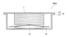
図3Aに示す第三実施形態の二次電池RB3は、膨張部材13と電極群1との間に、膨張部材13の中央部で変位自在に連結された二枚のプレートからなる押圧プレート15を介装した例である。また、真空引きしたときに、膨張部材13が膨らんで押圧プレート15が連結部で屈曲して、電極群1の中央部分を押圧している状態を模式的に示したものである。
The secondary battery RB3 of the third embodiment shown in FIG. 3A includes a
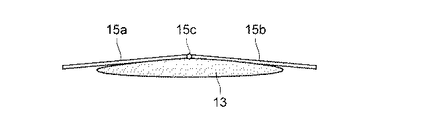
押圧プレート15は、図3Bに示すように、平板状の第一プレート15aと第二プレート15bとを連結部15cを介して変位自在に連結した構成とされる。この際に、連結部15cの構成は、例えば、二枚のプレートを柔軟性を有する樹脂やゴム材、伸縮性のあるテープなどで連結する方法が採用される。また、二枚のプレートを蝶番状に連結した構成であってもよく、特に限定するものではない。
As shown in FIG. 3B, the
真空時に膨張部材13が膨らむと図3Cに示すように、連結部15cを押し上げる。このように少なくとも二枚のプレートを変位自在に連結した押圧プレート15を介装することで、真空時に膨張部材13が凸レンズ状に膨らんで連結部15cを押し上げて、電極群1の中央部分を押圧し、電極群1内部の空気を排気することができる。そのために、この構成であっても、電極群の中央部まで電解液を十分浸透させることができる。
When the
また、二枚の平板を変位自在に連結した構成の押圧プレート15は、常圧時には平坦であるので、厚み方向の寸法を抑えることができ、二次電池の余分な厚肉化を抑制することができる。
In addition, the
減圧時に膨らんで電極群1を圧迫して内部の空気を押し出す膨張部材13は、密封された袋状であればよく、耐熱性と耐薬品性と絶縁性を備える樹脂材、例えば、ポリエチレンやポリプロピレン材からなる袋体を用いることができる。
The
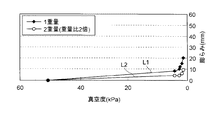
また、ポリエチレン製の膨張部材13を用いて、所定の荷重を付加した状態で膨らみを確認する実験を行った。その結果を図5に示す。
In addition, an experiment for confirming the bulge in a state where a predetermined load was applied was performed using the
図中に示す膨張ラインL1は、電極群1に相当する荷重(1重量)を付加した状態で。減圧したときの、膨らみ量を示す。また、前記1重量の2倍の荷重(2重量)を付加した状態の膨らみ量を膨張ラインL2で示している。
The expansion line L1 shown in the figure is in a state where a load (1 weight) corresponding to the
例えば、膨張ラインL1では、真空度が50kPaで膨らみ量が0であり、真空度が3kPaで膨らみ量が10mmとなり、真空度が2kPaで膨らみ量が15mmとなり、真空度が1.5kPaで膨らみ量が20mmとなる実験例を示している。 For example, in the expansion line L1, the degree of expansion is 0 at a vacuum level of 50 kPa, the amount of expansion is 10 mm when the degree of vacuum is 3 kPa, the amount of expansion is 15 mm when the degree of vacuum is 2 kPa, and the amount of expansion when the degree of vacuum is 1.5 kPa. Shows an experimental example in which becomes 20 mm.
また、荷重を2倍とした膨張ラインL2では、真空度が50kPaで膨らみ量が0であり、真空度が3kPaで膨らみ量が4mmとなり、真空度が2kPaで膨らみ量が6mmとなり、真空度が1.5kPaで膨らみ量が9mmとなる結果が得られた。 Further, in the expansion line L2 in which the load is doubled, the bulge amount is 0 when the degree of vacuum is 50 kPa, the bulge amount is 4 mm when the degree of vacuum is 3 kPa, the bulge amount is 6 mm when the degree of vacuum is 2 kPa, and the degree of vacuum is The result that the bulge amount was 9 mm at 1.5 kPa was obtained.
この実験から判るように、所定の真空度まで真空引きすることで、膨張部材13を介して、電極群1の中央部分を所定の押圧力で圧迫することが可能である。そのために、膨張部材13を介装する本実施形態によれば、排気され難い電極群の中央部分の空気を押し出すことができ、電極群の中央部まで電解液を十分浸透させることができる。
As can be seen from this experiment, it is possible to press the central portion of the
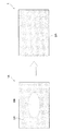
そのために、図4に示すように、膨張部材13を介装していない状態では、電極群1Aの内部では、電解液が浸透している浸透部分DAと浸透していない未浸透部分DBが存在し、膨張部材13を介装した電極群1の内部では、電解液が浸透していない未浸透部分DBが存在せず、一様に電解液が浸透している浸透部分DAとなる。
Therefore, as shown in FIG. 4, in the state where the
次に、実際に作製したリチウム二次電池について説明する。 Next, the actually produced lithium secondary battery will be described.
(実施例)
[正極板の作製]
正極活物質としてのLiFePO4(90重量部)と、導電材としてのアセチレンブラック(5重量部)と、結着材としてのポリフッ化ビニリデン(5重量部)と、を混合し、溶媒としてのN−メチル−2−ピロリドンを適宜加えて各材料を分散させてスラリーを調製し、このスラリーを正極集電体としてのアルミニウム箔(厚み20μm)の両面上に均一に塗布して乾燥させた後、ロールプレスで圧縮し、所定のサイズで切断して板状の正極板2を作製した。
(Example)
[Preparation of positive electrode plate]
LiFePO4 (90 parts by weight) as a positive electrode active material, acetylene black (5 parts by weight) as a conductive material, and polyvinylidene fluoride (5 parts by weight) as a binder are mixed, and N- A slurry is prepared by appropriately adding methyl-2-pyrrolidone to disperse each material, and the slurry is uniformly applied on both sides of an aluminum foil (
また、作製した正極板のサイズは、140mm×250mmで、厚みは230μmであって、この正極板2を32枚用いた。
Moreover, the size of the produced positive electrode plate was 140 mm × 250 mm, the thickness was 230 μm, and 32
[負極板の作製]
負極活物質としての天然黒鉛(90重量部)と、結着材としてのポリフッ化ビニリデン(10重量部)と、を混合し、溶媒としてのN−メチル−2−ピロリドンを適宜加えて各材料を分散させてスラリーを調製し、このスラリーを負極集電体としての銅箔(厚み16μm)の両面上に均一に塗布して乾燥させた後、ロールプレスで圧縮し、所定のサイズで切断して板状の負極板3を作製した。
[Preparation of negative electrode plate]
Natural graphite (90 parts by weight) as a negative electrode active material and polyvinylidene fluoride (10 parts by weight) as a binder are mixed, and N-methyl-2-pyrrolidone as a solvent is appropriately added to each material. A slurry is prepared by dispersing, and the slurry is uniformly applied on both sides of a copper foil (thickness 16 μm) as a negative electrode current collector and dried, then compressed by a roll press, and cut into a predetermined size. A plate-like
また、作製した負極板のサイズは、142mm×255mmで、厚みは146μmであって、この負極板2を33枚用いた。
Further, the size of the prepared negative electrode plate was 142 mm × 255 mm, the thickness was 146 μm, and 33
また、セパレータとして、サイズ145mm×255mmで、厚み25μmのポリエチレンフィルムを64枚作製した。 In addition, as a separator, 64 polyethylene films having a size of 145 mm × 255 mm and a thickness of 25 μm were prepared.
[非水電解液の作製]
エチレンカーボネート(EC)とジエチルカーボネート(DEC)とを、30:70の容積比で混合した混合液(溶媒)に、LiPF6を1mol/L溶解して非水電解液を調整した。
[Preparation of non-aqueous electrolyte]
A non-aqueous electrolyte was prepared by dissolving 1 mol / L of LiPF 6 in a mixed solution (solvent) in which ethylene carbonate (EC) and diethyl carbonate (DEC) were mixed at a volume ratio of 30:70.
[電池缶の作製]
電池缶を構成する外装ケースおよび蓋部材の材料としては、ニッケルメッキされた鉄板を用いてそれぞれ作製した。また、そのいずれもが、厚み0.8mmで、長手方向×短手方向×深さ、がそれぞれ内寸で、320mm×150mm×40mmの電池缶サイズで、開閉可能な注入口栓付き角型リチウム二次電池を作製した。また、蓋部材を電極群の上面に密着させるために、平板状ではなく、缶の内部に嵌まり込む皿型状の蓋部材を用いる構成とした。皿型状の蓋部材を用いると、蓋部材を溶接する際に動くのを防止できて、溶接作業が容易となる。また、皿型状の落ち込み量を変更することで、収容する電極群の厚みの変化に容易に対応できる。さらに、皿型状であれば、蓋部材の強度、および電池缶の強度を向上することが可能となって好ましい。
[Production of battery cans]
As materials for the outer case and the lid member constituting the battery can, nickel-plated iron plates were used, respectively. In addition, each of them has a thickness of 0.8 mm, a longitudinal direction × a lateral direction × a depth, and each internal size, 320 mm × 150 mm × 40 mm battery can size, and can be opened and closed with a rectangular lithium with an inlet plug A secondary battery was produced. Moreover, in order to make a lid member closely_contact | adhere to the upper surface of an electrode group, it was set as the structure which uses the plate-shaped lid member which fits in the inside of a can instead of flat form. When the dish-shaped lid member is used, it is possible to prevent the lid member from moving when welding the lid member, and the welding operation is facilitated. Moreover, it can respond easily to the change of the thickness of the electrode group to accommodate by changing the amount of depressions of a dish shape. Furthermore, a dish shape is preferable because the strength of the lid member and the strength of the battery can can be improved.
[二次電池の組立]
正極板と負極板とをセパレータを介して交互に積層する。その際に、正極板に対して負極板が外側に位置するように、正極版32枚、負極板33枚、セパレータ64枚を積層し、この積層体をセパレータと同じ厚み25μmのポリエチレンフィルムを用いて巻回する構成として、電極群(積層体)を構築した。
[Assembly of secondary battery]
A positive electrode plate and a negative electrode plate are alternately laminated via a separator. At that time, 32 positive electrode plates, 33 negative electrode plates, and 64 separators were laminated so that the negative electrode plate was located outside the positive electrode plate, and this laminate was used a polyethylene film having the same thickness of 25 μm as the separator. An electrode group (laminated body) was constructed as a structure to be wound.
正負の極板間に介装するセパレータの大きさは前述したように、サイズ145mm×255mmであり、正極板(140×250)、負極板(142×255)よりも少し大きなサイズである。これにより、正極板および負極板に形成された活物質層を確実に被覆することができる。また、正極の集電体露出部および負極の集電体露出部に、集電部材(集電端子)の接続片を接続した。 As described above, the size of the separator interposed between the positive and negative electrode plates is 145 mm × 255 mm, which is slightly larger than the positive electrode plate (140 × 250) and the negative electrode plate (142 × 255). Thereby, the active material layer formed on the positive electrode plate and the negative electrode plate can be reliably coated. Moreover, the connection piece of the current collection member (current collection terminal) was connected to the current collector exposed portion of the positive electrode and the current collector exposed portion of the negative electrode.
集電端子を接続した電極群を外装ケースに収容し、集電端子と外部端子とを接続し、蓋部材を取り付けて密封し、注液孔から非水電解液を減圧注液した。注液後に、注液孔を封口して、それぞれの実施形態の二次電池を10個ずつ作製した。 The electrode group to which the current collector terminal was connected was housed in an outer case, the current collector terminal and the external terminal were connected, a lid member was attached and sealed, and the nonaqueous electrolyte was injected under reduced pressure from the liquid injection hole. After the liquid injection, the liquid injection holes were sealed, and 10 secondary batteries of each embodiment were produced.
実施例1は、第一実施形態の二次電池RB1に相当する二次電池であって、膜厚0.1mmで平坦時厚みが0.5mmの膨張部材を介装した例である。また、その形状は、平坦時の平面視で楕円形であって、セパレータのサイズ145mm×255mmに対して、短径70mm、長径120mmとしている。 Example 1 is a secondary battery corresponding to the secondary battery RB1 of the first embodiment, in which an expansion member having a film thickness of 0.1 mm and a flat thickness of 0.5 mm is interposed. Further, the shape is an ellipse in a plan view when flat, and the short diameter is 70 mm and the long diameter is 120 mm with respect to the separator size of 145 mm × 255 mm.
実施例2は、第二実施形態の二次電池RB2に相当する二次電池であって、同じ膨張部材に加えて板厚1mmの硬質樹脂製の湾曲プレートを介装した例である。また、この湾曲プレートは、所定の曲率で凸レンズ状に湾曲した形状とされたものである。実施例3は、第三実施形態の二次電池RB3に相当する二次電池であって、膨張部材に加えて板厚1mmの二枚の硬質樹脂製の押圧プレートを介装した例である。これらの湾曲プレートと押圧プレートの幅は、当接する積層面の中央部分を効率よく押圧するために、積層面の幅よりも短い幅で膨張部材が好ましく、ここではセパレータの幅145mmに対して100mm程度の幅としている。また、長さはセパレータの長寸255mm程度である。 Example 2 is a secondary battery corresponding to the secondary battery RB2 of the second embodiment, in which a curved plate made of hard resin having a plate thickness of 1 mm is interposed in addition to the same expansion member. In addition, the curved plate has a shape curved in a convex lens shape with a predetermined curvature. Example 3 is a secondary battery corresponding to the secondary battery RB3 of the third embodiment, and is an example in which two hard resin press plates having a plate thickness of 1 mm are interposed in addition to the expansion member. The width of the curved plate and the pressing plate is preferably a width shorter than the width of the laminated surface in order to efficiently press the central portion of the laminated surface that comes into contact, and here the expansion member is 100 mm with respect to the separator width of 145 mm. It is about the width. The length is about 255 mm of the separator.
[比較例の作製]
比較例の二次電池として、先に示した実施例で使用した電極群(積層体)を同様に使用し、同じサイズの電池缶に組み込んで、膨張部材を用いない二次電池を作製した。この場合でも、電極群の上面に蓋部材に設ける凸部が密着する構成としている。つまり、膨張部材の平坦時厚みの分、蓋部材に設ける凸部の段深さが深くなった構成である。
[Production of Comparative Example]
As the secondary battery of the comparative example, the electrode group (laminated body) used in the above-described examples was used in the same manner, and assembled into a battery can of the same size to produce a secondary battery without using an expansion member. Even in this case, the convex portion provided on the lid member is in close contact with the upper surface of the electrode group. That is, the step depth of the protrusion provided on the lid member is increased by the flat thickness of the expansion member.
実施例1〜3の各10個と比較例10個の二次電池を用いて、充電容量を確認した。また、確認された充電容量が低いサンプルを分解して、電極群内部の電解液浸透具合を確認した。この実験結果を表1に示す。 The charge capacity was confirmed using 10 each of Examples 1 to 3 and 10 comparative batteries. Moreover, the sample with the low charge capacity confirmed was decomposed | disassembled, and the electrolyte solution penetration | infiltration state inside an electrode group was confirmed. The experimental results are shown in Table 1.
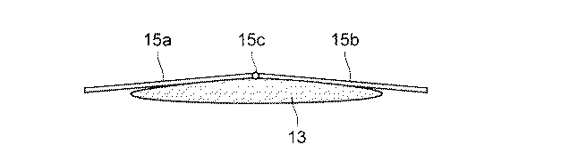
表1に示すように、実施例1〜3で、充電容量が最も低いサンプル1個を分解して、電極群内部の電解液の浸透具合を確認したところ、一様に電解液が浸透していることが確認できて、全て正常であった。また、これらの充電容量がいずれも設計容量の93%以上であることから当然であると理解できる。 As shown in Table 1, in Examples 1 to 3, one sample with the lowest charge capacity was disassembled and the penetration of the electrolyte inside the electrode group was confirmed. All were normal. In addition, it can be understood that these charge capacities are all 93% or more of the design capacity.
膨張部材13を介装していない比較例1で、充電容量が低いサンプル2個を選んで分解調査したところ、2個共に電極群内部に電解液が浸透していない未浸透部分が生じていることが判った。また、このことも、充電容量が設計容量の60%程度しか満足していないことから当然であると理解できる。
In Comparative Example 1 in which the
上記したように、本実施形態に係る膨張部材13を介装した二次電池であれば、正極板と負極板とセパレータとを数十層積層した大型の電極群であっても、電極群の内部まで電解液を確実に浸透させることが可能となる。また、電極群内部への電解液染み込み性が向上するので、電解液が浸透するまでの時間が長くならず、電解液注液工程の生産性が低下しない。
As described above, if the secondary battery includes the
次に、電極群の内部まで電解液を確実に浸透させることが可能な二次電池の製造方法についてさらに説明する。 Next, a method for manufacturing a secondary battery capable of reliably infiltrating the electrolyte into the electrode group will be further described.
本実施形態に係る二次電池の製造方法は、正極板と負極板とをセパレータを介して複数層積層した電極群と、この電極群を収容する外装ケースと、前記外装ケースを密閉する蓋部材とを備え、これらの外装ケースと蓋部材とで構成される電池缶の内部に前記外装ケースに設けられる注液口から電解液が注液され前記電極群の内部まで浸透して充填される二次電池の製造方法である。また、電極群と該電極群が載置される外装ケースの底面との間、もしくは、電極群と蓋部材との間、の少なくとも一方に、常圧時には平坦で、真空時に膨らむ膨張部材を介装し、電池缶の内部を真空にして膨張部材を所定量膨らませた後で電解液を注入するようにしている。 The method for manufacturing a secondary battery according to the present embodiment includes an electrode group in which a plurality of layers of a positive electrode plate and a negative electrode plate are stacked via a separator, an outer case that houses the electrode group, and a lid member that seals the outer case The electrolyte solution is injected into a battery can constituted by the outer case and the lid member from a liquid inlet provided in the outer case, and penetrates into the electrode group to be filled. This is a method for manufacturing a secondary battery. Further, at least one of the electrode group and the bottom surface of the outer case on which the electrode group is placed or between the electrode group and the lid member is provided with an expansion member that is flat during normal pressure and expands during vacuum. And the inside of the battery can is evacuated to inflate the expansion member by a predetermined amount, and then the electrolyte is injected.
この製造方法であれば、真空時に膨らむので、電極群を圧迫して内部に残留している空気を押し出すことができる。そのために、電極群の内部の空気を十分排気した後で電解液を注液する構成となって、電極群内部への電解液染み込み性が向上して電極群の内部まで電解液を確実に浸透させることができる二次電池の製造方法となる。 In this manufacturing method, since it swells in a vacuum, the electrode group can be pressed to push out air remaining inside. Therefore, after the air inside the electrode group is sufficiently exhausted, the electrolyte solution is injected to improve the penetration of the electrolyte solution into the electrode group and to ensure that the electrolyte solution penetrates into the electrode group. The manufacturing method of the secondary battery which can be made to become.
上記したように、本実施形態に係る二次電池の製造方法は、外装ケースに電極群を収容して蓋部材を装着して密閉された電池缶を作製する第一工程と、電池缶内を減圧して膨張体を膨らます第二工程と、電池缶内に電解液を注液する第三工程とを備えている。このような構成であれば、電池缶内を減圧して膨張体を膨らます第二工程を備えているので、真空時に電極群の中央部を押圧して内部の空気を積極的に押し出すことができ、電解液を電極群内部まで十分浸透させることが可能となる。つまり、電解液を電極群内部まで浸透させるための準備を確実に実行することができる。 As described above, the manufacturing method of the secondary battery according to the present embodiment includes the first step of manufacturing the sealed battery can by housing the electrode group in the outer case and attaching the lid member, and the inside of the battery can. A second step of expanding the expansion body by reducing the pressure and a third step of injecting an electrolyte into the battery can are provided. With such a configuration, since the second step of expanding the expansion body by decompressing the inside of the battery can is provided, it is possible to positively push out the internal air by pressing the central part of the electrode group during vacuum. The electrolyte solution can be sufficiently penetrated into the electrode group. That is, it is possible to reliably execute preparation for allowing the electrolytic solution to penetrate into the electrode group.
また、膨張部材は、平面視円形もしくは平面視楕円形の袋状とされ、真空時に凸レンズ状に膨らむことが好ましい。この構成であれば、真空時に凸レンズ状に膨らんで、電極群の中央部分を押圧する構成となり、排気され難い中央部分の空気を押し出す作用を発揮し、空気を残らず排出して、電極群の中央部まで電解液を浸透させることができる。 Further, the inflating member is preferably a bag shape having a circular shape in plan view or an elliptical shape in plan view, and is preferably inflated into a convex lens shape in a vacuum. If it is this configuration, it becomes a configuration that swells like a convex lens during vacuum and presses the central part of the electrode group, exerts the action of pushing out the air of the central part that is difficult to be exhausted, exhausts all the air, and discharges the electrode group Electrolyte can be penetrated to the central part.
また、膨張部材と電極群との間に所定の曲率で凸レンズ状に湾曲する湾曲プレートを介装した製造方法が好ましい。この構成であれば、真空時に膨張部材を膨らませて、湾曲プレートを湾曲させることで電極群の所定領域を押圧して、空気が抜け難い電極群の中央部の空気を十分排出することができる。 Further, a manufacturing method in which a curved plate that curves in a convex lens shape with a predetermined curvature is interposed between the expansion member and the electrode group is preferable. With this configuration, the expansion member is inflated at the time of vacuum, and the curved plate is bent to press the predetermined region of the electrode group, so that the air at the center of the electrode group that is difficult to remove air can be sufficiently discharged.
また、膨張部材と電極群との間に、膨張部材の中央部で変位自在に連結された二枚のプレートからなる押圧プレートを介装した製造方法であってもよい。この構成であれば、真空時に凸レンズ状に膨らむ膨張部材により、二枚のプレートからなる押圧プレートの連結部が押し上げられるので、電極群の中央部分を確実に押圧して排気することができて、電解液を電極群の内部まで十分浸透させることができる。 Moreover, the manufacturing method which interposed the press plate which consists of two plates displaceably connected by the center part of the expansion member between the expansion member and the electrode group may be sufficient. With this configuration, the connecting portion of the pressing plate composed of two plates is pushed up by the expansion member that swells in the shape of a convex lens at the time of vacuum, so that the central portion of the electrode group can be reliably pressed and exhausted, The electrolyte can be sufficiently penetrated into the electrode group.
上記したように、本発明によれば、電極群と該電極群が載置される前記外装ケースの底面との間、もしくは、電極群と蓋部材との間、の少なくとも一方に、常圧時には平坦で、真空時に膨らむ膨張部材を介装したので、正極板と負極板とセパレータとを数十層積層した大型の電極群であっても、電極群の内部まで電解液を確実に浸透させることができる二次電池およびその製造方法を得ることができる。 As described above, according to the present invention, at least one of the electrode group and the bottom surface of the outer case on which the electrode group is placed, or between the electrode group and the lid member, is under normal pressure. Because it is flat and has an expansion member that swells in a vacuum, the electrolyte solution can be reliably infiltrated into the electrode group even in the case of a large electrode group in which several tens of layers of a positive electrode plate, a negative electrode plate, and a separator are laminated. A secondary battery that can be manufactured and a method for manufacturing the same can be obtained.
また、膨張部材と電極群との間に所定の曲率で凸レンズ状に湾曲する湾曲プレート、または、中央部で変位自在に連結された二枚のプレートからなる押圧プレートを介装して、電極群の所定領域を押圧して、空気が抜け難い電極群の中央部の空気を十分排出することができる。 In addition, an electrode group is interposed between the expansion member and the electrode group with a curved plate curved in a convex lens shape with a predetermined curvature, or a pressing plate composed of two plates movably connected at the center. By pressing the predetermined area, the air in the center of the electrode group that is difficult to remove air can be sufficiently discharged.
また、電極群の内部に空気が残留しないので、大型サイズの電極群を用いた大容量の二次電池であっても、設計容量を満足することができ、安定した電池容量を維持することが可能な二次電池およびその製造方法となる。 In addition, since air does not remain inside the electrode group, the design capacity can be satisfied even with a large capacity secondary battery using a large-sized electrode group, and a stable battery capacity can be maintained. A secondary battery and a method for manufacturing the same are possible.
そのために、本発明に係る二次電池は、大型化および性能安定化が求められる大容量の蓄電池に好適に利用可能となる。 Therefore, the secondary battery according to the present invention can be suitably used for a large-capacity storage battery that is required to be increased in size and stabilized in performance.
1 電極群
2 正極板
3 負極板
4 セパレータ
10 電池缶
11 外装ケース
12 蓋部材
13 膨張部材
14 湾曲プレート
15 押圧プレート
RB、RB1〜RB3 二次電池
DESCRIPTION OF
Claims (10)
前記電極群の積層方向の前記外装ケースの底面と前記電極群との間、もしくは、前記電極群と前記蓋部材との間、の少なくとも一方に、常圧時には平坦で、真空時に膨らむ膨張部材を介装したことを特徴とする二次電池。 An electrode group in which a plurality of layers of a positive electrode plate and a negative electrode plate are laminated via a separator, an exterior case that accommodates the electrode group, and a lid member that seals the exterior case, and the exterior case and the lid member A secondary battery in which an electrolytic solution is injected into a configured battery can and penetrates and fills the inside of the electrode group,
An expansion member that is flat at normal pressure and expands at vacuum is provided between at least one of the bottom surface of the outer case and the electrode group in the stacking direction of the electrode group, or between the electrode group and the lid member. A secondary battery characterized by being interposed.
前記電極群の積層方向の前記外装ケースの底面と前記電極群との間、もしくは、前記電極群と前記蓋部材との間、の少なくとも一方に、常圧時には平坦で、真空時に膨らむ膨張部材を介装し、前記電池缶の内部を真空にして前記膨張部材を所定量膨らませた後で前記電解液を注入することを特徴とする二次電池の製造方法。 An electrode group in which a plurality of layers of a positive electrode plate and a negative electrode plate are laminated via a separator, an exterior case that accommodates the electrode group, and a lid member that seals the exterior case, and the exterior case and the lid member A method of manufacturing a secondary battery in which an electrolyte is injected into a battery can configured and penetrates and fills the inside of the electrode group,
An expansion member that is flat at normal pressure and expands at vacuum is provided between at least one of the bottom surface of the outer case and the electrode group in the stacking direction of the electrode group, or between the electrode group and the lid member. A method for producing a secondary battery, comprising interposing, inflating the expansion member by a predetermined amount by evacuating the inside of the battery can, and then injecting the electrolytic solution.
Priority Applications (1)
| Application Number | Priority Date | Filing Date | Title |
|---|---|---|---|
| JP2010292143A JP2012142099A (en) | 2010-12-28 | 2010-12-28 | Secondary battery and manufacturing method thereof |
Applications Claiming Priority (1)
| Application Number | Priority Date | Filing Date | Title |
|---|---|---|---|
| JP2010292143A JP2012142099A (en) | 2010-12-28 | 2010-12-28 | Secondary battery and manufacturing method thereof |
Publications (1)
| Publication Number | Publication Date |
|---|---|
| JP2012142099A true JP2012142099A (en) | 2012-07-26 |
Family
ID=46678196
Family Applications (1)
| Application Number | Title | Priority Date | Filing Date |
|---|---|---|---|
| JP2010292143A Pending JP2012142099A (en) | 2010-12-28 | 2010-12-28 | Secondary battery and manufacturing method thereof |
Country Status (1)
| Country | Link |
|---|---|
| JP (1) | JP2012142099A (en) |
Cited By (5)
| Publication number | Priority date | Publication date | Assignee | Title |
|---|---|---|---|---|
| CN108336257A (en) * | 2017-12-28 | 2018-07-27 | 广州倬粤动力新能源有限公司 | A kind of horizon battery |
| US10978749B2 (en) | 2016-12-15 | 2021-04-13 | Lg Chem, Ltd. | Method for injecting electrolyte to pouch secondary battery using gap-controlling jig |
| CN113994534A (en) * | 2019-07-10 | 2022-01-28 | 本田技研工业株式会社 | Power storage module and method of manufacturing power storage module |
| CN114512726A (en) * | 2020-11-16 | 2022-05-17 | 泰星能源解决方案有限公司 | Method for producing nonaqueous electrolyte secondary battery |
| CN116247393A (en) * | 2023-04-01 | 2023-06-09 | 河南鹏辉循环科技有限公司 | A prismatic battery structure with automatic liquid replenishment |
-
2010
- 2010-12-28 JP JP2010292143A patent/JP2012142099A/en active Pending
Cited By (12)
| Publication number | Priority date | Publication date | Assignee | Title |
|---|---|---|---|---|
| US10978749B2 (en) | 2016-12-15 | 2021-04-13 | Lg Chem, Ltd. | Method for injecting electrolyte to pouch secondary battery using gap-controlling jig |
| CN108336257A (en) * | 2017-12-28 | 2018-07-27 | 广州倬粤动力新能源有限公司 | A kind of horizon battery |
| CN108336257B (en) * | 2017-12-28 | 2020-09-01 | 广州倬粤动力新能源有限公司 | a horizontal battery |
| CN113994534A (en) * | 2019-07-10 | 2022-01-28 | 本田技研工业株式会社 | Power storage module and method of manufacturing power storage module |
| CN113994534B (en) * | 2019-07-10 | 2024-04-02 | 本田技研工业株式会社 | Electric storage module and method of manufacturing electric storage module |
| CN114512726A (en) * | 2020-11-16 | 2022-05-17 | 泰星能源解决方案有限公司 | Method for producing nonaqueous electrolyte secondary battery |
| EP4002535A1 (en) * | 2020-11-16 | 2022-05-25 | Prime Planet Energy & Solutions, Inc. | Method for producing nonaqueous electrolyte secondary battery |
| JP2022079233A (en) * | 2020-11-16 | 2022-05-26 | プライムプラネットエナジー&ソリューションズ株式会社 | Method for manufacturing non-aqueous electrolyte secondary battery |
| JP7249982B2 (en) | 2020-11-16 | 2023-03-31 | プライムプラネットエナジー&ソリューションズ株式会社 | Method for manufacturing non-aqueous electrolyte secondary battery |
| CN114512726B (en) * | 2020-11-16 | 2024-05-03 | 泰星能源解决方案有限公司 | Method for manufacturing nonaqueous electrolyte secondary battery |
| US12494512B2 (en) | 2020-11-16 | 2025-12-09 | Prime Planet Energy & Solutions, Inc. | Method for producing nonaqueous electrolyte secondary battery |
| CN116247393A (en) * | 2023-04-01 | 2023-06-09 | 河南鹏辉循环科技有限公司 | A prismatic battery structure with automatic liquid replenishment |
Similar Documents
| Publication | Publication Date | Title |
|---|---|---|
| KR101304870B1 (en) | Method for Manufacturing Battery Cell and Battery Cell Manufactured Thereby | |
| KR101334623B1 (en) | Degassing Method of Secondary Battery Using Centrifugal Force | |
| KR102264739B1 (en) | Negative electrode active material, preparing method of the same, negative electrode and lithium secondary battery including the same | |
| JP2013008550A (en) | Secondary battery and manufacturing method thereof | |
| CN111886722B (en) | Method for pre-lithiating negative electrode of secondary battery | |
| JP5541957B2 (en) | Multilayer secondary battery | |
| JP3831939B2 (en) | battery | |
| US20120100413A1 (en) | Secondary battery and assembled battery | |
| KR101455165B1 (en) | Electrode Assembly of Improved Stability and Secondary Battery the Same | |
| JP2000235868A (en) | Non-aqueous electrolyte secondary battery | |
| CN106159123B (en) | Secondary cell | |
| KR20130126365A (en) | Manufacturing method of lithium secondary battery | |
| KR20160037518A (en) | Cylindrical Battery Including Pressuring Part and Manufacturing Method for the Same | |
| JP2013033688A (en) | Secondary battery | |
| JP5798050B2 (en) | Secondary battery, storage battery system using the secondary battery, and maintenance method | |
| CN105684193A (en) | Method for manufacturing non-aqueous electrolyte secondary battery | |
| JP2004139961A (en) | Battery manufacturing method and battery | |
| CN115411343A (en) | Lithium ion secondary battery | |
| JP2014032873A (en) | Secondary battery | |
| KR101519372B1 (en) | Manufacture Device of Battery Cell | |
| JP2012142099A (en) | Secondary battery and manufacturing method thereof | |
| CN114467194A (en) | Device for prelithiating an anode and method for prelithiating an anode | |
| KR101598650B1 (en) | Negative-electrode and lithium secondary battery with high capacity comprising the same | |
| CN115411238A (en) | Lithium ion secondary battery | |
| KR101307772B1 (en) | Method for Manufacturing Secondary Battery and Secondary Battery Manufactured thereby |