JP2012143444A - Putter head - Google Patents
Putter head Download PDFInfo
- Publication number
- JP2012143444A JP2012143444A JP2011004939A JP2011004939A JP2012143444A JP 2012143444 A JP2012143444 A JP 2012143444A JP 2011004939 A JP2011004939 A JP 2011004939A JP 2011004939 A JP2011004939 A JP 2011004939A JP 2012143444 A JP2012143444 A JP 2012143444A
- Authority
- JP
- Japan
- Prior art keywords
- slit
- face insert
- face
- putter head
- toe
- Prior art date
- Legal status (The legal status is an assumption and is not a legal conclusion. Google has not performed a legal analysis and makes no representation as to the accuracy of the status listed.)
- Pending
Links
Images




Classifications
-
- A—HUMAN NECESSITIES
- A63—SPORTS; GAMES; AMUSEMENTS
- A63B—APPARATUS FOR PHYSICAL TRAINING, GYMNASTICS, SWIMMING, CLIMBING, OR FENCING; BALL GAMES; TRAINING EQUIPMENT
- A63B53/00—Golf clubs
- A63B53/04—Heads
- A63B53/0487—Heads for putters
-
- A—HUMAN NECESSITIES
- A63—SPORTS; GAMES; AMUSEMENTS
- A63B—APPARATUS FOR PHYSICAL TRAINING, GYMNASTICS, SWIMMING, CLIMBING, OR FENCING; BALL GAMES; TRAINING EQUIPMENT
- A63B60/00—Details or accessories of golf clubs, bats, rackets or the like
- A63B60/52—Details or accessories of golf clubs, bats, rackets or the like with slits
-
- A—HUMAN NECESSITIES
- A63—SPORTS; GAMES; AMUSEMENTS
- A63B—APPARATUS FOR PHYSICAL TRAINING, GYMNASTICS, SWIMMING, CLIMBING, OR FENCING; BALL GAMES; TRAINING EQUIPMENT
- A63B2209/00—Characteristics of used materials
-
- A—HUMAN NECESSITIES
- A63—SPORTS; GAMES; AMUSEMENTS
- A63B—APPARATUS FOR PHYSICAL TRAINING, GYMNASTICS, SWIMMING, CLIMBING, OR FENCING; BALL GAMES; TRAINING EQUIPMENT
- A63B53/00—Golf clubs
- A63B53/04—Heads
- A63B53/0416—Heads having an impact surface provided by a face insert
-
- A—HUMAN NECESSITIES
- A63—SPORTS; GAMES; AMUSEMENTS
- A63B—APPARATUS FOR PHYSICAL TRAINING, GYMNASTICS, SWIMMING, CLIMBING, OR FENCING; BALL GAMES; TRAINING EQUIPMENT
- A63B53/00—Golf clubs
- A63B53/04—Heads
- A63B53/0416—Heads having an impact surface provided by a face insert
- A63B53/042—Heads having an impact surface provided by a face insert the face insert consisting of a material different from that of the head
-
- A—HUMAN NECESSITIES
- A63—SPORTS; GAMES; AMUSEMENTS
- A63B—APPARATUS FOR PHYSICAL TRAINING, GYMNASTICS, SWIMMING, CLIMBING, OR FENCING; BALL GAMES; TRAINING EQUIPMENT
- A63B53/00—Golf clubs
- A63B53/04—Heads
- A63B53/0416—Heads having an impact surface provided by a face insert
- A63B53/042—Heads having an impact surface provided by a face insert the face insert consisting of a material different from that of the head
- A63B53/0425—Heads having an impact surface provided by a face insert the face insert consisting of a material different from that of the head the face insert comprising two or more different materials
-
- A—HUMAN NECESSITIES
- A63—SPORTS; GAMES; AMUSEMENTS
- A63B—APPARATUS FOR PHYSICAL TRAINING, GYMNASTICS, SWIMMING, CLIMBING, OR FENCING; BALL GAMES; TRAINING EQUIPMENT
- A63B53/00—Golf clubs
- A63B53/04—Heads
- A63B53/0458—Heads with non-uniform thickness of the impact face plate
Landscapes
- Health & Medical Sciences (AREA)
- General Health & Medical Sciences (AREA)
- Physical Education & Sports Medicine (AREA)
- Golf Clubs (AREA)
Abstract
【課題】ボールにトップスピンがかかり易く、かつこのトップスピンのかけ易さの温度依存性が小さいパターヘッドを提供する。
【解決手段】ヘッド本体2の前面(フェース面)に凹部2Hが設けられ、この凹部2H内にフェースインサート3が配置されている。このフェースインサート3の底面から上方に向ってスリット3aが設けられている。スリット3aは、フェースインサート3のトウ側端部近傍からヒール側端部近傍まで延在している。スリット3aの下端部はフェースインサート3の後縁に位置している。スリット3aの天井面はトウ側からヒール側に向ってアーチ状となっている。スリット3aに粘弾性材3bが充填されてもよい。
【選択図】図1Provided is a putter head in which a topspin is easily applied to a ball and the temperature dependency of the ease of applying the topspin is small.
A concave portion 2H is provided on the front surface (face surface) of a head main body 2, and a face insert 3 is disposed in the concave portion 2H. A slit 3 a is provided upward from the bottom surface of the face insert 3. The slit 3 a extends from the vicinity of the toe side end of the face insert 3 to the vicinity of the heel side end. The lower end of the slit 3 a is located at the rear edge of the face insert 3. The ceiling surface of the slit 3a has an arch shape from the toe side toward the heel side. The slit 3a may be filled with a viscoelastic material 3b.
[Selection] Figure 1
Description
本発明は、ゴルフのパターのパターヘッドに関するものであり、特にヘッド本体のフェース面にフェースインサートを装着したパターヘッドに関するものである。 The present invention relates to a putter head of a golf putter, and more particularly to a putter head having a face insert attached to the face surface of a head body.
ゴルフのパターは、主としてグリーン上においてボールをヒットしてボールをカップに向けて転がす用途に用いられるクラブである。特開2007−117635には、パターヘッドのフェース面にフェースインサートを装着して打感を柔らかくすることが記載されている。 A golf putter is a club used mainly for hitting a ball on a green and rolling the ball toward a cup. Japanese Patent Application Laid-Open No. 2007-117635 describes that a face insert is attached to the face surface of a putter head to soften the hit feeling.
特開2001−62008には、フェース面の下部に合成樹脂発泡体を一体に設けることによりトップスピンをかけ易くしたパターヘッドが記載されている。しかしながら、合成樹脂発泡体は特性の温度依存性が強いので、気温によってトップスピンのかかり方がかなり変化する。 Japanese Patent Application Laid-Open No. 2001-62008 describes a putter head in which a synthetic resin foam is integrally provided at a lower portion of a face surface to easily apply top spin. However, since the synthetic resin foam has a strong temperature dependency of characteristics, the top spin is considerably changed depending on the temperature.
本発明は、通常のパターに比べボールを打った時にボールのバックスピンが減少し、ひいては、ボールにトップスピンがかかり易く、かつこのトップスピンのかけ易さの温度依存性が小さいパターヘッドを提供することを目的とする。 The present invention provides a putter head in which the back spin of the ball is reduced when hitting the ball as compared with a normal putter, and thus the top spin is easily applied to the ball, and the temperature dependency of the ease of applying the top spin is small. The purpose is to do.
請求項1のパターヘッドは、ヘッド本体のフェース面にフェースインサートを装着したパターヘッドにおいて、該フェースインサートに、該フェースインサートの底面から上方に切り込まれたスリットが設けられており、該スリットよりもフェース面側の前面部と該スリットよりも後面側の後面部とが該スリットよりもトウ側及びヒール側において連なっていることを特徴とするものである。
The putter head according to
請求項2のパターヘッドは、請求項1において、前記スリットはフェースインサートのトウ側端部近傍からヒール側端部近傍まで延在していることを特徴とするものである。
The putter head according to
請求項3のパターヘッドは、請求項1又は2において、前記スリットは、フェースインサートのトウ・ヒール方向の中央部において最も深くなっており、該中央部からトウ側及びヒール側に向って連続的に又は段階的に浅くなっていることを特徴とするものである。 A putter head according to a third aspect of the present invention is the putter head according to the first or second aspect, wherein the slit is deepest at a central portion in a toe-heel direction of the face insert, and continuously from the central portion toward the toe side and the heel side. It is characterized by becoming shallower or gradually.
請求項4のパターヘッドは、請求項1ないし3のいずれか1項において、該スリットに粘弾性材が充填されていることを特徴とするものである。 A putter head according to a fourth aspect is characterized in that, in any one of the first to third aspects, the slit is filled with a viscoelastic material.
本発明のパターヘッドのフェースインサートには、底面から上方に向って切り込まれた形状のスリットが設けられている。そのため、ボールをヒットしたときにフェースインサートの前面部の下部が後退し、バックスピンが減少し、ボールにトップスピンがかかり易いものとなり、ヒットされたボールの直進性が良好となる。 The face insert of the putter head according to the present invention is provided with a slit having a shape cut upward from the bottom surface. Therefore, when the ball is hit, the lower part of the front surface portion of the face insert is retracted, the backspin is reduced, the topspin is easily applied to the ball, and the straightness of the hit ball is improved.
このスリットのトウ側及びヒール側において、フェースインサートの前面部と後面部とが連なっているので、フェースインサートは強度及び耐久性に優れる。 Since the front surface portion and the rear surface portion of the face insert are continuous on the toe side and the heel side of the slit, the face insert is excellent in strength and durability.
このスリットは、フェースインサートのトウ側端部近傍からヒール側端部近傍まで延在していることが好ましい。 This slit preferably extends from the vicinity of the toe side end of the face insert to the vicinity of the heel side end.
このスリットに粘弾性材を充填することにより、打球音や、打感の調節を行うことができる。 By filling the slit with a viscoelastic material, it is possible to adjust the hitting sound and feel.
以下、図面を参照して実施の形態について説明する。 Hereinafter, embodiments will be described with reference to the drawings.
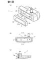
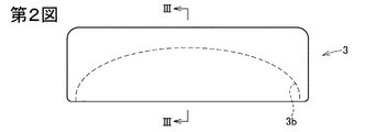
第1図〜第4図は第1の実施の形態に係るパターヘッド1を示すものである。このパターヘッド1では、ヘッド本体2の前面(フェース面)に凹部2Hが設けられ、この凹部2H内にフェースインサート3が配置されている。この実施の形態では、ヘッド本体2はアルミ合金、チタン合金、銅合金、ステンレスなどの金属製である。フェースインサート3は、ポリエステル、ナイロン、ウレタンなどの合成樹脂又はアルミ合金、銅合金、ステンレスなどの金属よりなる。フェースインサート3の前面と、凹部2Hの周囲のヘッド本体2の前面とは面一である。
1 to 4 show a
凹部2H及びフェースインサート3は、横長の略長方形状である。凹部2Hの深さは全体として均一であり、フェースインサート3の厚さも全体として均一である。ただし、部分的に深い箇所及び厚い部位を設けたり、逆に部分的に浅い箇所及び薄い部位を設けてもよい。
The
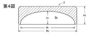
フェースインサート3の左右幅及び上下幅は凹部2Hよりも若干小さいものとなっており、フェースインサート3の上下左右の側面3Sと凹部2Hの周面2Sとの間には若干の空隙4があいている。この空隙4の幅は0.3〜1.5mm特に0.4〜1.0mm程度が好適である。フェースインサート3の大きさは上下幅H0が16〜30mm特に18〜25mm、左右幅W0が50〜150mm特に70〜100mm、厚さが2〜10mm特に3〜8mm程度が好ましいが、これに限定されない。
The left and right widths and vertical widths of the
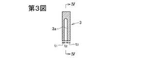
第2図〜第4図に明示の通り、このフェースインサート3にあっては、その底面から上方に向って切り込まれた形状のスリット3aが設けられている。スリット3aは、フェースインサート3のトウ側端部近傍からヒール側端部近傍まで延在している。フェースインサート3のトウ側及びヒール側の側端面にはスリット3aは到達していない。スリット3aよりも前面(フェース面)側の前面部と、スリット3aよりも後面側の後面部とは、このフェースインサート3のトウ側端部及びヒール側端部において連なっている。また、フェースインサート3のトウ側端部及びヒール側端部の底面は、フェースインサート3の該前面部及び後面部の底面と面一となっている。
As clearly shown in FIGS. 2 to 4, the
このスリット3aは、トウ・ヒール方向(パターヘッドの正面視において左右方向)の中央付近において最も深くなっており、この中央付近からトウ側及びヒール側に向って徐々に浅くなっている。この実施の形態では、第4図において、スリット3aの天井面は略半楕円形のアーチ状となっている。
The
この実施の形態において、スリット3aのトウ・ヒール方向の長さW1は、フェースインサート3のトウ・ヒール方向の長さW0の80〜98%特に85〜90%であることが好ましい。
In this embodiment, the toe-heel direction length W 1 of the
第3図の通り、この実施の形態においては、フェース面を鉛直とした状態において、スリット3aは、鉛直方向に設けられている。また、スリット3bの前後方向の幅(スリット厚み)t2は全体にわたって均等となっている。この実施の形態では、スリット3aよりもフェース面側の前面部の厚みt1は、後面部の厚みt3よりも小さくなっており、スリット3aは、フェースインサート3の厚み方向の中間よりも若干フェース面側に位置しているが、中間に位置してもよい。フェースインサート3の全体の厚み(t1+t2+t3)に対し、スリット3aの厚みt2の比率は10〜50%特に25〜45%程度であることが好ましく、t1の比率は10〜50%特に25〜40%程度であることが好ましい。
As shown in FIG. 3, in this embodiment, the
このスリット3aは、フェースインサート3の素板に対し切削加工を施すことにより容易に形成することができるが、フェースインサート3を合成樹脂製とする場合には、射出成形用金型にスリット3aに相当する凸部を中子等により形成しておくことにより、フェースインサートの成形時にスリット3aを併せて形成するようにしてもよい。
The
フェースインサート3は、第3図の左側面がパターのフェース前面となるように凹部2H内に配置され、反対側が接着剤によって凹部2Hの奥壁面に接着される。接着剤としては、エポキシ系接着剤、ゴム系接着剤、両面テープなどが好適であるが、これに限定されない。
The
このように構成されたパターヘッド1のホゼル部1hにシャフトを連結することによりパターが構成される。このパターでパッティング(グリーン上のボールをフェース面で打つこと)すると、ボールをヒットしたときにフェースインサート3の前面部(スリット3aよりもフェース側)が若干後退することにより、トップスピンがかかり易くなり、ヒットされたボールの直進性が良好となる。また、このフェースインサート3の前面部の変形特性は気温の変化に殆ど影響されず、トップスピンのかかり易さに温度依存性が殆どない。
A putter is configured by connecting a shaft to the
本発明では、第5図のようにスリット3aに粘弾性材3bを充填してもよい。粘弾性材としてはゴム、エラストマー、軟質合成樹脂などが用いられる。スリット3aに粘弾性材を充填すると、ボールをヒットしたときの打球音や打感を調節することができる。この粘弾性材は、フェースインサートの前面部の変形特性に殆ど影響せず、トップスピンのかかり易さに温度依存性は実質的にない。
In the present invention, the
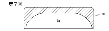
上記実施の形態のフェースインサート3では、スリット3aの天井面はトウ側からヒール側にかけて半楕円形のアーチ状となっており、トウ・ヒール方向の中央付近からトウ側及びヒール側に向って連続的に低く(即ち、スリット3aが浅く)なっているが、第6図のフェースインサート3Aのようにトウ・ヒール方向の中央付近からトウ側及びヒール側に向って段階的に低くなってもよい。また、第7図のフェースインサート3Bのように、トウ・ヒール方向の中央付近ではスリット3aの深さはトウ・ヒール方向において一定であり、トウ側近傍及びヒール側近傍においてトウ側及びヒール側に向って徐々に(又は段階的に)浅くなるようにしてもよい。
In the
本発明では、第8図のフェースインサート3Dのように、スリット3aと、フェースインサート3Dのトウ側側端面及びヒール側側端面とを連通する浅い溝部3dを設けてもよい。この浅い溝部3dの深さH2は、フェースインサート3Dの高さH0の20%以下特に15%以下であることが好ましい。なお、H2を過度に大きくすると、(例えば、H2を前述のH1と同等にすると、)ボールを打ったときのボールの反発性が低くなる。H2をH0の20%以下(0%を含む。)とすると、ボールの反発性が高くなり、ボールの転がる距離が長くなる。
In the present invention, as in the
本発明では、第9図(a)のフェースインサート3Eのように、スリット3aを上部ほどフェース側となるように前傾状態としてもよく、逆に、第9図(b)のフェースインサート3Fのように後傾させてもよい。
In the present invention, like the
上記実施の形態では、フェースインサートの前面は平坦となっているが、横長の溝を複数本平行に設けてもよい。溝の幅員(上下幅)は0.3〜1.6mm程度が好適であり、溝の深さは0.05〜1.1mm程度が好ましい。 In the above embodiment, the front surface of the face insert is flat, but a plurality of horizontally long grooves may be provided in parallel. The width (vertical width) of the groove is preferably about 0.3 to 1.6 mm, and the depth of the groove is preferably about 0.05 to 1.1 mm.
第1図では、フェースインサート3の周囲に空隙4を形成しているが、第10図のようにこの空隙に、ゴム、エラストマー、合成樹脂などの粘弾性材8を配材してもよい。また、第11図のパターヘッド1’のように、空隙4が生じないようにフェースインサート3を凹部2Hにぴったりと嵌まるように構成してもよい。
In FIG. 1, the
第10,11図のその他の構成は第1図と同様であり、同一符号は同一部分を示している。なお、フェースインサート3の側面3Sと凹部2Hの周面2Sとの間に空隙4や粘弾性材8を設けると、フェースインサートの反発特性が設計通りになるという効果が得られる。
Other configurations in FIGS. 10 and 11 are the same as those in FIG. 1, and the same reference numerals denote the same parts. In addition, if the space |
1,1’ パターヘッド
2 ヘッド本体
2H 凹部
3,3A,3B,3D,3E,3F フェースインサート
3a スリット
3b 粘弾性材
1, 1 '
Claims (4)
該フェースインサートに、該フェースインサートの底面から上方に切り込まれたスリットが設けられており、
該スリットよりもフェース面側の前面部と該スリットよりも後面側の後面部とが該スリットよりもトウ側及びヒール側において連なっていることを特徴とするパターヘッド。 In a putter head with a face insert attached to the face surface of the head body,
The face insert is provided with a slit cut upward from the bottom surface of the face insert,
A putter head characterized in that a front surface portion on the face surface side of the slit and a rear surface portion on the rear surface side of the slit are continuous on the toe side and the heel side of the slit.
Priority Applications (2)
| Application Number | Priority Date | Filing Date | Title |
|---|---|---|---|
| JP2011004939A JP2012143444A (en) | 2011-01-13 | 2011-01-13 | Putter head |
| US13/340,045 US20120184392A1 (en) | 2011-01-13 | 2011-12-29 | Putter head |
Applications Claiming Priority (1)
| Application Number | Priority Date | Filing Date | Title |
|---|---|---|---|
| JP2011004939A JP2012143444A (en) | 2011-01-13 | 2011-01-13 | Putter head |
Publications (1)
| Publication Number | Publication Date |
|---|---|
| JP2012143444A true JP2012143444A (en) | 2012-08-02 |
Family
ID=46491180
Family Applications (1)
| Application Number | Title | Priority Date | Filing Date |
|---|---|---|---|
| JP2011004939A Pending JP2012143444A (en) | 2011-01-13 | 2011-01-13 | Putter head |
Country Status (2)
| Country | Link |
|---|---|
| US (1) | US20120184392A1 (en) |
| JP (1) | JP2012143444A (en) |
Families Citing this family (3)
| Publication number | Priority date | Publication date | Assignee | Title |
|---|---|---|---|---|
| US9782645B2 (en) | 2014-11-10 | 2017-10-10 | Dunlop Sports Co. Ltd. | Golf club head |
| US9474948B2 (en) * | 2014-11-10 | 2016-10-25 | Dunlop Sports Co. Ltd. | Golf club head |
| US12029947B1 (en) * | 2022-08-22 | 2024-07-09 | Cobra Golf Incorporated | Golf club head |
Citations (4)
| Publication number | Priority date | Publication date | Assignee | Title |
|---|---|---|---|---|
| US5013A (en) * | 1847-03-13 | Improvement in apparatus for the manufacture of malleable iron | ||
| US5023A (en) * | 1847-03-20 | Stocking-loom | ||
| JP2004525706A (en) * | 2001-03-29 | 2004-08-26 | クライブ アクティーゼルスカブ | Golf putter |
| US7341527B1 (en) * | 2005-06-22 | 2008-03-11 | Fisher Dale P | Golf putter with multiple striking-surfaces, reversible face plate |
Family Cites Families (9)
| Publication number | Priority date | Publication date | Assignee | Title |
|---|---|---|---|---|
| US1154490A (en) * | 1915-02-05 | 1915-09-21 | Robert Hobart Davis | Golf-club. |
| US1359220A (en) * | 1919-05-22 | 1920-11-16 | Richard F Beamer | Wooden golf-club |
| US1854548A (en) * | 1927-03-08 | 1932-04-19 | James B Hunt | Golf club head |
| US3061310A (en) * | 1959-09-04 | 1962-10-30 | Adolf E Giza | Hollow headed golf putter |
| US3989248A (en) * | 1974-12-26 | 1976-11-02 | Pepsico, Inc. | Golf club having insert capable of elastic flexing |
| JPH0586368U (en) * | 1992-04-27 | 1993-11-22 | ダイワゴルフ株式会社 | Golf club head |
| US6979270B1 (en) * | 1999-06-24 | 2005-12-27 | Vardon Golf Company, Inc. | Golf club face flexure control system |
| JP2001137398A (en) * | 1999-11-18 | 2001-05-22 | Bridgestone Sports Co Ltd | Wood club head |
| US6390932B1 (en) * | 2000-04-18 | 2002-05-21 | Callaway Golf Company | Compliant polymer face golf club head |
-
2011
- 2011-01-13 JP JP2011004939A patent/JP2012143444A/en active Pending
- 2011-12-29 US US13/340,045 patent/US20120184392A1/en not_active Abandoned
Patent Citations (4)
| Publication number | Priority date | Publication date | Assignee | Title |
|---|---|---|---|---|
| US5013A (en) * | 1847-03-13 | Improvement in apparatus for the manufacture of malleable iron | ||
| US5023A (en) * | 1847-03-20 | Stocking-loom | ||
| JP2004525706A (en) * | 2001-03-29 | 2004-08-26 | クライブ アクティーゼルスカブ | Golf putter |
| US7341527B1 (en) * | 2005-06-22 | 2008-03-11 | Fisher Dale P | Golf putter with multiple striking-surfaces, reversible face plate |
Also Published As
| Publication number | Publication date |
|---|---|
| US20120184392A1 (en) | 2012-07-19 |
Similar Documents
| Publication | Publication Date | Title |
|---|---|---|
| US9821203B2 (en) | Golf club head | |
| US9731177B2 (en) | Golf club head | |
| US9079081B2 (en) | Iron head | |
| US8790192B2 (en) | Putter head | |
| JP5219482B2 (en) | Golf putter head and golf putter | |
| JP5508227B2 (en) | Putter-type golf club head and putter-type golf club | |
| US8622850B2 (en) | Putter head | |
| JP2022524964A (en) | Multi-part golf club head | |
| US8663028B2 (en) | Golf club head | |
| JP6123468B2 (en) | Iron type golf club head | |
| JP2008154974A (en) | Putter head | |
| US20110319189A1 (en) | Putter head | |
| JP5540994B2 (en) | Putter head | |
| JP2012143444A (en) | Putter head | |
| JP6015060B2 (en) | Putter head | |
| JP5617383B2 (en) | Putter head | |
| US20230001274A1 (en) | Putter head provided with intermediate member | |
| JP2012235828A (en) | Iron head | |
| JP2012125503A (en) | Putter head | |
| JP5290722B2 (en) | Golf putter head | |
| JP2012100867A (en) | Putter head | |
| JP2012080960A (en) | Putter head | |
| JP2009136490A (en) | Golf club head | |
| JP2012125504A (en) | Putter head | |
| JP2012135343A (en) | Putter head |
Legal Events
| Date | Code | Title | Description |
|---|---|---|---|
| A621 | Written request for application examination |
Free format text: JAPANESE INTERMEDIATE CODE: A621 Effective date: 20131217 |
|
| A131 | Notification of reasons for refusal |
Free format text: JAPANESE INTERMEDIATE CODE: A131 Effective date: 20140722 |
|
| A977 | Report on retrieval |
Free format text: JAPANESE INTERMEDIATE CODE: A971007 Effective date: 20140723 |
|
| A02 | Decision of refusal |
Free format text: JAPANESE INTERMEDIATE CODE: A02 Effective date: 20141118 |