JP2012144125A - Baffle guide structure for vehicle - Google Patents
Baffle guide structure for vehicle Download PDFInfo
- Publication number
- JP2012144125A JP2012144125A JP2011003237A JP2011003237A JP2012144125A JP 2012144125 A JP2012144125 A JP 2012144125A JP 2011003237 A JP2011003237 A JP 2011003237A JP 2011003237 A JP2011003237 A JP 2011003237A JP 2012144125 A JP2012144125 A JP 2012144125A
- Authority
- JP
- Japan
- Prior art keywords
- vehicle
- guide
- pair
- wind guide
- grille
- Prior art date
- Legal status (The legal status is an assumption and is not a legal conclusion. Google has not performed a legal analysis and makes no representation as to the accuracy of the status listed.)
- Pending
Links
Images
Landscapes
- Cooling, Air Intake And Gas Exhaust, And Fuel Tank Arrangements In Propulsion Units (AREA)
Abstract
【課題】車両の軽衝突時に横ガイドが後退して熱交換器を損傷させることを防止又は効果的に抑制することができる車両用導風ガイド構造を得る。
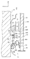
【解決手段】本車両用導風ガイド構造では、ロアグリル36を通過した冷却風が、導風ガイド42及びロアアブソーバ40によって整流されてラジエータ32へと導かれる。一方、自動車12が前面衝突をした際には、車両後方側へ後退してくるロアグリル36からの荷重によって導風ガイド42が変形する。ここで、この導風ガイド42は、横ガイド48の高剛性部48Aよりも車両前方側の部位が、高剛性部48Aを含む車両後方側の部位に比しロアグリル36側からの荷重に対して低剛性に形成されている。このため、上述の如く導風ガイド42が変形する際には、導風ガイド42における高剛性部48Aよりも車両前方側の部位が優先的に変形することにより、高剛性部48A(横ガイド48の後部)の後退が抑制される。
【選択図】図2The present invention provides a wind guide structure for a vehicle that can prevent or effectively prevent a lateral guide from retreating and damaging a heat exchanger during a light vehicle collision.
In the vehicle wind guide structure, cooling air that has passed through a lower grill is rectified by a wind guide and a lower absorber and guided to a radiator. On the other hand, when the automobile 12 has a frontal collision, the wind guide 42 is deformed by the load from the lower grill 36 that moves backward toward the vehicle rear side. Here, in the wind guide 42, a portion of the lateral guide 48 on the front side of the high-rigidity portion 48A is more resistant to a load from the lower grill 36 side than a portion on the vehicle rear side including the high-rigidity portion 48A. It is formed with low rigidity. For this reason, when the air guide 42 is deformed as described above, the vehicle front side portion of the air guide 42 is preferentially deformed with respect to the highly rigid portion 48A, so that the high rigidity portion 48A (the lateral guide 48) is deformed. (Rear part) is suppressed.
[Selection] Figure 2
Description
本発明は、熱交換器に冷却風を導く車両用導風ガイド構造に関する。 The present invention relates to a vehicle wind guide structure for guiding cooling air to a heat exchanger.
下記特許文献1に示された車両の前部構造では、バンパカバーと一体に形成された導風ガイドがバンパリインフォースメント下部に沿って配置されており、この導風ガイドによってバンパカバーの空気導入口へと導かれる冷却風が、ラジエータやインタークーラーに供給される。 In the front structure of a vehicle shown in Patent Document 1 below, an air guide formed integrally with the bumper cover is arranged along the lower part of the bumper reinforcement, and the air guide port of the bumper cover is formed by the air guide. Cooling air that is led to is supplied to the radiator and the intercooler.
しかしながら、上述の如き車両の前部構造では、車両が前面衝突(軽衝突)をした際等に、導風ガイド(横ガイド)がバンパカバー等と共にラジエータ側へ後退し、ラジエータ(熱交換器)の特に冷却フィンを損傷させる可能性がある。 However, in the front structure of the vehicle as described above, when the vehicle has a frontal collision (light collision), the wind guide (lateral guide) moves backward to the radiator side together with the bumper cover and the like, and the radiator (heat exchanger) In particular, it may damage the cooling fins.
本発明は上記事実を考慮し、車両の軽衝突時に横ガイドが後退して熱交換器を損傷させることを防止又は効果的に抑制することができる車両用導風ガイド構造を得ることを目的としている。 In consideration of the above facts, the present invention has an object to obtain a wind guide structure for a vehicle that can prevent or effectively suppress a lateral guide from retreating and damaging a heat exchanger at the time of a light vehicle collision. Yes.
請求項1に記載の発明に係る車両用導風ガイド構造は、車両のフロントグリルに対して車両後方側に配置され、車両上下方向に延在する左右一対の上下骨格部材を含んで構成された車体前部の骨格構造と、前記一対の上下骨格部材の間に配置され、前記骨格構造によって支持された熱交換器とを有する車両に適用され、前記一対の上下骨格部材と前記フロントグリルとの間に配置された左右一対の縦ガイド、及び、前記一対の縦ガイド間に掛け渡され、後端が前記熱交換器と対向した横ガイドを含んで構成され、前記フロントグリルから導入される冷却風を前記熱交換器へ導くと共に、前記横ガイドの後部よりも車両前方側の部位が前記後部を含む車両後方側の部位に比し前記フロントグリル側からの荷重に対して低剛性に形成された導風ガイドを備えている。 The vehicle wind guide structure according to the first aspect of the invention includes a pair of left and right upper and lower skeleton members that are disposed on the vehicle rear side with respect to the vehicle front grille and extend in the vehicle vertical direction. Applied to a vehicle having a skeletal structure at the front of a vehicle body and a heat exchanger disposed between the pair of upper and lower skeleton members and supported by the skeleton structure, the pair of upper and lower skeleton members and the front grille Cooling introduced from the front grille, including a pair of left and right vertical guides disposed between and a horizontal guide spanned between the pair of vertical guides and having a rear end facing the heat exchanger The wind is guided to the heat exchanger, and a portion on the vehicle front side with respect to the rear portion of the lateral guide is formed with low rigidity with respect to a load from the front grille side as compared with a portion on the vehicle rear side including the rear portion. Wind guide It is equipped with a de.
請求項1に記載の車両用導風ガイド構造では、車体前部の骨格構造を構成する左右一対の上下骨格部材の間に熱交換器が配置されており、一対の上下骨格部材とフロントグリルとの間には、導風ガイドを構成する左右一対の縦ガイドが配置されている。さらに、一対の縦ガイド間には、導風ガイドを構成する横ガイドが後端を熱交換器に対向させた状態で配置されており、フロントグリルから導入される冷却風は、当該導風ガイドによって熱交換器へと導かれる。 In the vehicle wind guide structure according to claim 1, the heat exchanger is disposed between the pair of left and right upper and lower skeleton members constituting the skeleton structure of the front portion of the vehicle body, and the pair of upper and lower skeleton members, the front grille, A pair of left and right vertical guides constituting the air guide are arranged between the two. Further, between the pair of vertical guides, a horizontal guide constituting the air guide is arranged with the rear end facing the heat exchanger, and the cooling air introduced from the front grill is the air guide. To the heat exchanger.
一方、車両が軽衝突をした際には、車両後方側へ後退してくるフロントグリルからの荷重によって、導風ガイドの一対の縦ガイドが一対の上下骨格部材に押し当てられる。この状態で更にフロントグリルが後退してくると、導風ガイドがフロントグリルからの荷重によって変形する。 On the other hand, when the vehicle has a light collision, the pair of vertical guides of the wind guide are pressed against the pair of upper and lower skeleton members by the load from the front grille that moves backward toward the rear of the vehicle. When the front grill is further retracted in this state, the air guide is deformed by the load from the front grill.
ここで、上述の導風ガイドは、横ガイドの後部よりも車両前方側の部位が、当該後部を含む車両後方側の部位に比しフロントグリル側からの荷重に対して低剛性に形成されている。このため、上述の如く導風ガイドが変形する際には、横ガイドの後部よりも車両前方側の部位が優先的に変形することにより、横ガイドの後部の後退が抑制される。これにより、横ガイドの後退による熱交換器の損傷を防止又は効果的に抑制することができる。 Here, the wind guide described above is formed such that a portion on the front side of the vehicle from the rear portion of the lateral guide is formed with low rigidity with respect to a load from the front grille side as compared with a portion on the rear side of the vehicle including the rear portion. Yes. For this reason, when the wind guide is deformed as described above, the rear portion of the lateral guide is restrained from retreating by preferentially deforming the front portion of the vehicle rather than the rear portion of the lateral guide. Thereby, damage to the heat exchanger due to the receding of the lateral guide can be prevented or effectively suppressed.
請求項2に記載の発明に係る車両用導風ガイド構造は、請求項1に記載の車両用導風ガイド構造において、前記横ガイドは、前記後部が前記一対の縦ガイドに結合されると共に、前記後部から前記フロントグリル側へ延びる本体部が前記フロントグリル及び前記一対の縦ガイドに対して非結合とされ又は脆弱部を介して結合されていることを特徴としている。
The vehicle wind guide structure according to the invention described in
請求項2に記載の車両用導風ガイド構造では、導風ガイドは、横ガイドの後部が一対の縦ガイドに結合されている。このため、フロントグリル側からの荷重によって一対の縦ガイドが一対の上下骨格部材に押し当てられることにより、横ガイドの後退が抑制される。この状態で更にフロントグリルが後退してくると、横ガイドの後部からフロントグリル側へ延びる横ガイドの本体部に対して、フロントグリル側から荷重が負荷される。この本体部は、フロントグリル及び一対の縦ガイドに対して非結合とされ又は脆弱部を介して結合されており、横ガイドの後部よりも変形し易くされている。このため、横ガイドの本体部がフロントグリルからの荷重によって変形することにより、横ガイドの後部に入力される荷重が低減される。これにより、横ガイドの後部の後退を抑制することができるので、導風ガイドの構成を簡単なものにすることができる。 In the vehicle wind guide structure according to the second aspect, the rear portion of the horizontal guide is coupled to the pair of vertical guides. For this reason, the pair of vertical guides are pressed against the pair of upper and lower skeleton members by the load from the front grille side, thereby suppressing the backward movement of the horizontal guides. When the front grill is further retracted in this state, a load is applied from the front grill side to the main body portion of the horizontal guide extending from the rear portion of the horizontal guide to the front grill side. The main body portion is not connected to the front grill and the pair of vertical guides or is connected via a fragile portion, and is more easily deformed than the rear portion of the horizontal guide. For this reason, the main body portion of the horizontal guide is deformed by the load from the front grille, so that the load input to the rear portion of the horizontal guide is reduced. Thereby, since the back of a rear part of a horizontal guide can be suppressed, the structure of a wind guide can be simplified.
請求項3に記載の発明に係る車両用導風ガイド構造は、請求項1又は請求項2に記載の車両用導風ガイド構造において、前記導風ガイドは、前記横ガイドの前記後部の車両幅方向端部から車両後方側へ延出された当てリブを有し、当該当てリブの後端が前記上下骨格部材に対して車両前方側から対向して配置されていることを特徴としている。
The vehicle wind guide structure according to claim 3 is the vehicle wind guide structure according to
請求項3に記載の車両用導風ガイド構造では、導風ガイドに対してフロントグリル側から荷重が負荷された際には、横ガイドの後部の車両幅方向端部から車両後方側へ延出された当てリブの後端が、上下骨格部材に押し当てられる。これにより、横ガイドの後部の後退を良好に抑制することができる。 In the vehicle wind guide structure according to claim 3, when a load is applied to the wind guide from the front grille side, the vehicle guide extends from the vehicle width direction end of the rear part of the side guide to the vehicle rear side. The rear end of the applied rib is pressed against the upper and lower skeleton members. Thereby, the backward movement of the rear part of the lateral guide can be satisfactorily suppressed.
請求項4に記載の発明に係る車両用導風ガイド構造は、請求項1〜請求項3の何れか1項に記載の車両用導風ガイド構造において、前記フロントグリル、前記一対の縦ガイド、及び前記横ガイドが一体に形成されていることを特徴としている。 The vehicle wind guide structure according to the invention described in claim 4 is the vehicle wind guide structure according to any one of claims 1 to 3, wherein the front grille, the pair of vertical guides, In addition, the lateral guide is integrally formed.
請求項4に記載の車両用導風ガイド構造では、フロントグリル、一対の縦ガイド及び横ガイドが一体に形成されているため、部品の一体化により低コスト化を図ることができる。また、一対の縦ガイドとフロントグリルとの間に隙間が生じることがないので、車両の空力性能及び熱交換器の冷却性能を向上させることができる。 In the vehicle wind guide structure according to the fourth aspect, since the front grille, the pair of vertical guides and the horizontal guide are integrally formed, the cost can be reduced by integrating the parts. Further, since no gap is generated between the pair of vertical guides and the front grille, the aerodynamic performance of the vehicle and the cooling performance of the heat exchanger can be improved.
請求項5に記載の発明に係る車両用導風ガイド構造は、請求項1〜請求項3の何れか1項に記載の車両用導風ガイド構造において、前記フロントグリルは、ロアグリルであり、当該ロアグリルと、前記一対の上下骨格部材の下端部間に掛け渡された左右骨格部材との間にロアアブソーバが配置されると共に、前記ロアグリル、前記一対の縦ガイド、前記横ガイド及び前記ロアアブソーバが一体に形成されていることを特徴としている。 The vehicle wind guide structure according to the invention described in claim 5 is the vehicle wind guide structure according to any one of claims 1 to 3, wherein the front grill is a lower grill, A lower absorber is disposed between the lower grille and the left and right skeleton members spanned between the lower ends of the pair of upper and lower skeleton members, and the lower grille, the pair of vertical guides, the lateral guides, and the lower absorbers It is characterized by being integrally formed.
請求項5に記載の車両用導風ガイド構造では、ロアグリルと、一対の上下骨格部材の下端部間に掛け渡された左右骨格部材との間に、ロアアブソーバが配置されている。このため、ロアアブソーバによって冷却風を熱交換器に案内することができる。しかも、ロアグリル、一対の縦ガイド、横ガイド及びロアアブソーバが一体に形成されているため、部品の一体化により低コスト化を図ることができる。さらに、一対の縦ガイドとロアグリルとの間、及び一対の縦ガイドとロアアブソーバとの間に隙間が生じることがないので、車両の空力性能及び熱交換器の冷却性能を向上させることができる。 In the vehicle wind guide structure according to the fifth aspect, the lower absorber is arranged between the lower grille and the left and right skeleton members spanned between the lower ends of the pair of upper and lower skeleton members. For this reason, the cooling air can be guided to the heat exchanger by the lower absorber. In addition, since the lower grille, the pair of vertical guides, the horizontal guides, and the lower absorber are integrally formed, the cost can be reduced by integrating the parts. Further, since no gap is generated between the pair of vertical guides and the lower grill and between the pair of vertical guides and the lower absorber, the aerodynamic performance of the vehicle and the cooling performance of the heat exchanger can be improved.
以上説明したように、本発明に係る車両用導風ガイド構造では、車両の軽衝突時に横ガイドが後退して熱交換器を損傷させることを防止又は効果的に抑制することができる。 As described above, in the vehicle wind guide structure according to the present invention, it is possible to prevent or effectively suppress the lateral guide from moving backward and damaging the heat exchanger during a light vehicle collision.
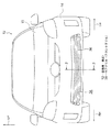
以下、図1〜図5参照して、本発明の実施形態に係る車両用導風ガイド構造10について説明する。なお、各図に適宜示される矢印FR、矢印UP、矢印LH、矢印RHは、それぞれ車両用導風ガイド構造10が適用された自動車12の前方向(進行方向)、上方向、左方向、右方向を示している。以下の説明において、単に前後、上下、左右の方向を用いる場合は、車両前後方向、車両上下方向、車両左右方向(車両幅方向)を示すものとする。
Hereinafter, with reference to FIGS. 1-5, the vehicle
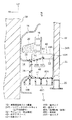
図1に示されるように、本実施形態に係る自動車12は、フロントバンパを構成するバンパカバー14を備えている。このバンパカバー14は、樹脂材料によって薄肉状に形成されており、図示しないネジ等によって車体の前端下部に固定されている。このバンパカバー14の車両後方側には、図2に示されるように、金属製のバンパリインフォースメント16が配置されている。
As shown in FIG. 1, the
バンパリインフォースメント16は、車両左右方向(車両幅方向)に沿って長尺な角筒状に形成されており、図3に示されるように、車体前部に車両前後方向に沿って延在する左右一対のフロントサイドメンバ18L、18Rの前端部に結合されている。バンパリインフォースメント16の前面には、長尺な発泡体からなるバンパアブソーバ20(図2参照。図3では図示省略)が、バンパリインフォースメント16に沿って取り付けられている。このバンパアブソーバ20は、車両前方から衝撃が作用すると変形し、当該衝撃を吸収する。
The
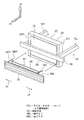
図2及び図3に示されるように、バンパリインフォースメント16の車両後方側には、金属材料によって正面視矩形枠状に形成されたラジエータサポート22が配置されている。ラジエータサポート22は、車両上下方向に延在する左右一対の上下骨格部材としてのラジエータサポートサイド24L、24Rと、ラジエータサポートサイド24L、24Rの下端部間に掛け渡された左右骨格部材としてのラジエータサポートロア26と、ラジエータサポートサイド24L、24Rの上端部間に掛け渡されたラジエータサポートアッパ28とを備えている。このラジエータサポート22は、ラジエータサポートサイド24L、24Rがフロントサイドメンバ18L、18Rに固定されており、フロントサイドメンバ18L、18Rと共に車体前部の骨格構造30を構成している。このラジエータサポート22には、熱交換器としてのラジエータ32が、該ラジエータサポート22の枠を埋めるように取り付けられている。このラジエータ32は、後述するロアグリル36から導入される冷却風とエンジン冷却水との間で熱交換を行う構成になっている。
As shown in FIGS. 2 and 3, a
一方、図2に示されるように、バンパカバー14には、バンパアブソーバ20よりも下方側において、空気導入口34が形成されている。この空気導入口34には、格子状に形成されたロアグリル36が装着されている。ロアグリル36の外枠部36Aには、車両前方側へ開口した溝38(図4参照)が形成されており、当該溝38に空気導入口34の周縁部が嵌合している。これにより、ロアグリル36がバンパカバー14に取り付けられている。
On the other hand, as shown in FIG. 2, an
ロアグリル36の下方には、ロアアブソーバ40が配置されている。ロアアブソーバ40は、バンパカバー14からラジエータサポートロア26の近傍まで延在しており、車幅方向には所定の幅(たとえば、ラジエータサポート22と同程度の幅)を有している。このロアアブソーバ40は、板状に形成され略水平(路面に対し平行)に配置された上板40Aと、この上板40Aの周囲から下方に延出された四角枠状の枠板40Bを備えている。さらに、枠板40Bの内側には、格子状に配置された複数のリブ40Cが設けられている。このロアアブソーバ40は、車両前方から衝撃が作用すると変形し、当該衝撃を吸収する。また、このロアアブソーバ40は、歩行者の衝突時に該歩行者の脚(膝下部分)を払うことで、該歩行者を自動車12のフード13の上に載せるのに寄与する構成とされている。
A
一方、ロアグリル36とラジエータサポートサイド24L、24Rとの間には、導風ガイド42を構成する左右一対の縦ガイド46L、46Rが配置されている。これらの縦ガイド46L、46Rは、板状に形成されており、板厚方向が車両幅方向に沿う状態で車両上下方向に延在している。これらの縦ガイド46L、46Rの上端側は、ロアグリル36の上端部よりも上方側へ突出しており、バンパリインフォースメント16の下端部近傍まで延長されている。左側の縦ガイド46Lは、左側のラジエータサポートサイド24Lとロアグリル36との間に配置されており、右側の縦ガイド46Rは、右側のラジエータサポートサイド24Rとロアグリル36との間に配置されている。
On the other hand, a pair of left and right
さらに、一対の縦ガイド46L、46Rの上端部間には、導風ガイド42を構成する横ガイド48が掛け渡されている。横ガイド48は、全体として長尺な板状に形成されており、長手方向が車両幅方向に沿い且つ板厚方向が略車両上下方向に沿う状態で配置されている。横ガイド48の後端は、ラジエータ32と対向しており、横ガイド48の後部は、高剛性部48Aとされている。この高剛性部48Aの上部には、車両幅方向から見て上面側が曲面状の断面略半円形に形成された補強リブ50が設けられている。これにより、高剛性部48Aの剛性が向上している。この高剛性部48Aは、車両左側の端部が縦ガイド46Lの上端側における車両前後方向中央部付近に結合されており、車両右側の端部が縦ガイド46Rの上端側における車両前後方向中央部付近に結合されている。この高剛性部48Aとラジエータ32との間には、冷却風を通過させるための大きな隙間52が確保されている。
Further, a
高剛性部48Aの前端からは、車両前方側の斜め下方側(ロアグリル36の上端部側)へ向けて本体部48B(低剛性部)が延出されている。本体部48Bは、高剛性部48Aよりも上下方向寸法が小さい板状に形成されている。この本体部48Bは、ロアグリル36及び縦ガイド46L、46Rに対して非結合とされており、本体部48Bとロアグリル36との間、及び本体部48Bと一対の縦壁部46L、46Rとの間には、隙間54が形成されている。つまり、本体部48Bは、高剛性部48Aのみに支持されており、高剛性部48Aと比較して車両前方側(ロアグリル36側)からの荷重に対する剛性が低く設定されている。
From the front end of the high-
さらに、高剛性部48Aの車両幅方向両端部からは、車両後方側へ向けて当てリブ56L、56Rが延出されている。左側の当てリブ56Lは、左側の縦ガイド46Lと一体に形成されており、当該縦ガイド46Lの後端面と同一面上に配置された後端面が左側のラジエータサポートサイド24Lに対して車両前方側から対向している。また、右側の当てリブ56Rは、右側の縦ガイド46Rと一体に形成されており、当該縦ガイド46Rの後端面と同一面上に配置された後端面が右側のラジエータサポートサイド24Rに対して車両前方側から対向している。
Further, the
これらの当てリブ56L、56Rは、横ガイド48の高剛性部48Aの車両後方側において縦ガイド46L、46Rの剛性を向上させている。つまり、この導風ガイド42(縦ガイド46L、46R、横ガイド48及び当てリブ56L、56R)では、横ガイド48の高剛性部48Aよりも車両前方側の部位が、高剛性部48Aを含む車両後方側の部位に比しロアグリル36側からの荷重に対して低剛性に形成されている。
These
なお、縦ガイド46L及び当てリブ56Lの後端面とラジエータサポートサイド24Lとの間、縦ガイド46R及び当てリブ56Rの後端面とラジエータサポートサイド24Rとの間、ロアアブソーバ40とラジエータサポートロア26との間には、僅かな隙間が確保されている。これらの隙間は、ゴム等からなる図示しないシール部材によって塞がれている。このため、導風ガイド42に対して車両前方側から荷重が負荷された際には、縦ガイド46L、46R及び当てリブ56L、56Rが上記シール部材を介してラジエータサポートサイド24L、24Rから反力を受ける構成になっている。
In addition, between the rear end surface of the
以上説明したロアグリル36、ロアアブソーバ40、及び導風ガイド42は、樹脂の射出成形等によって一体に形成されている。これらのロアグリル36、ロアアブソーバ40、及び導風ガイド42は、ロアグリル36から導入される冷却風を、ラジエータ32へと効率的に導く導風ダクトを構成している。なお、前記冷却風には、自動車12の走行に伴う走行風、及びラジエータ32の背面側に設けられた図示しないファンの作動により生じる空気流が含まれる。
The
次に、本実施形態の作用について説明する。 Next, the operation of this embodiment will be described.
上記構成の車両用導風ガイド構造10では、ロアグリル36を通過した冷却風が、一対の縦ガイド46L、46R、横ガイド48、及びロアアブソーバ40によって整流されてラジエータ32へと導かれる。これにより、自動車12の空力性能及びラジエータ32の冷却性能を向上させることができるので、自動車12の燃費が向上する。
In the vehicle
一方、自動車12が前面衝突(軽衝突)をした際には、衝突物58からの荷重がバンパカバー14を介してバンパアブソーバ20及びロアアブソーバ40に負荷される。これにより、バンパアブソーバ20及びロアアブソーバ40が変形し、当該変形に伴ってバンパカバー14がロアグリル36と共に車両後方側へ後退してくる。このため、ロアグリル36からの荷重によって、導風ガイド42の縦ガイド46L、46R及び当てリブ56L、56Rが、図示しないシール部材を介してラジエータサポートサイド24L、24Rに押し当てられる。この状態で更にロアグリル36が後退してくると、導風ガイド42がロアグリル36からの荷重によって変形する。
On the other hand, when the
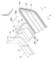
ここで、上述の導風ガイド42は、横ガイド48の高剛性部48Aよりも車両前方側の部位が、高剛性部48Aを含む車両後方側の部位に比しロアグリル36側からの荷重に対して低剛性に形成されている。このため、上述の如く導風ガイド42が変形する際には、図5に示されるように、横ガイド48の高剛性部48Aよりも車両前方側の部位が、高剛性部48Aを含む車両後方側の部位よりも優先的に変形する。これにより、横ガイド48の高剛性部48A(後部)の後退が抑制されるので、横ガイド48の後退によるラジエータ32の損傷を防止又は効果的に抑制することができる。
Here, in the
しかも、この横ガイド48は、縦ガイド46L、46Rに結合された高剛性部48Aからロアグリル36側へ延びる本体部48Bが、ロアグリル36及び縦ガイド46L、46Rに対して非結合とされており、本体部48Bが十分に弱体化されている。これにより、ロアグリル36からの荷重によって本体部48Bを確実に変形させることができるので、高剛性部48Aに入力される荷重を良好に低減することができ、高剛性部48A(横ガイド48の後部)の後退を良好に抑制することができる。また、本体部48Bとロアグリル36及び縦ガイド46L、46Rとの間に隙間54を形成するだけでよいため、導風ガイド42の構成を簡単なものにすることができる。
In addition, the
さらに、本実施形態では、導風ガイド42に対してロアグリル36側から荷重が負荷された際には、横ガイド48の高剛性部48Aの車両幅方向両端部から車両後方側へ延出された当てリブ56L、56Rの後端が、ラジエータサポートサイド24L、24Rに押し当てられる。これにより、横ガイド48の高剛性部48Aが車両後方側から直接的に支持されるので、高剛性部48Aの後退を良好に抑制することができる。
Furthermore, in the present embodiment, when a load is applied to the
また、本実施形態では、ロアグリル36、ロアアブソーバ40、及び導風ガイド42(縦ガイド46L、46R、横ガイド48、及び当てリブ56L、56R)が一体に形成されている。このため、部品の一体化により低コスト化を図ることができると共に、バンパカバー14側への組付工数を減じることができる。また、縦ガイド46L、46Rとロアグリル36との間、及び縦ガイド46L、46Rとロアアブソーバ40との間に隙間が生じることがないので、冷却風(走行風など)の整流効果を向上させることができ、走行風などの有効活用を図ることができる。これにより、自動車12の空力性能及びラジエータ32の冷却性能を向上させることができる。
In the present embodiment, the
なお、上記実施形態では、ロアグリル36、ロアアブソーバ40、及び導風ガイド42が一体に形成された構成にしたが、請求項1〜請求項3に係る発明はこれに限らず、これらが別体に形成された構成にしてもよい。
In the above embodiment, the
また、上記実施形態では、ロアアブソーバ40を備えた構成にしたが、請求項1〜請求項4に係る発明はこれに限らず、ロアアブソーバが省略された構成にしてもよい。
Moreover, in the said embodiment, although it was set as the structure provided with the
また、上記実施形態では、導風ガイド42がロアグリル36の車両後方側に配置された構成にしたが、請求項1〜請求項4に係る発明はこれに限らず、導風ガイドがアッパグリルの車両後方側に配置された構成にしてもよい。
Moreover, in the said embodiment, although the
また、上記実施形態に係る導風ガイド42では、横ガイド48の高剛性部48Aの車両幅方向両端部から車両後方側へ向けて当てリブ56L、56Rが延出された構成にしたが、請求項1及び請求項2に係る発明はこれに限らず、高剛性部48Aよりも車両後方側において縦ガイド46L、46Rの板厚を増加させる構成にしてもよい。
Further, in the
さらに、上記実施形態では、横ガイド48の本体部48Bがロアグリル36及び縦ガイド46L、46Rに対して非結合とされた構成にしたが、請求項1及び請求項2に係る発明はこれに限らず、本体部48Bがロアグリル36及び縦ガイド46L、46Rに対して低荷重で破断する脆弱部(薄肉部など)を介して結合(柔結合)された構成にしてもよい。この場合、本体部48Bとロアグリル36及び縦ガイド46L、46Rとの間の気密性を向上させることができるので、冷却風の整流効果を一層向上させることができる。また、上記実施形態において、本体部48Bとロアグリル36及び縦ガイド46L、46Rとの間の隙間に、ゴム等の弾性体からなるシール部材を嵌め込んで当該隙間を塞ぐ構成にしてもよい。この場合でも、冷却風の整流効果を一層向上させることができる。
Furthermore, in the said embodiment, although the main-
また、上記実施形態では、横ガイド48の本体部48Bがロアグリル36及び縦ガイド46L、46Rに対して非結合とされると共に、高剛性部48Aの車両後方側に当てリブ56L、56Rが設けられることにより、導風ガイド42の前部側と後部側とに剛性差を設定する構成にしたが、請求項1に係る発明はこれに限らず、導風ガイド42における剛性差の設定方法は適宜変更することができる。
In the above embodiment, the
また、上記実施形態では、ラジエータ32へと導風ガイド42が冷却風を導く構成にしたが、請求項1に係る発明はこれに限らず、冷却風とエアコン冷媒との間で熱交換を行うコンデンサへと導風ガイドが冷却風を導く構成にしてもよい。この場合、車体全部の骨格構造を構成する左右一対の上下骨格部材の間にコンデンサが配置される構成になる。
In the above-described embodiment, the
その他、本発明は上記実施形態に限定されるものではなく種々変更して実施できる。また、本発明の権利範囲が上記実施形態に限定されないことは言うまでもない。 In addition, the present invention is not limited to the above embodiment, and can be implemented with various modifications. Needless to say, the scope of rights of the present invention is not limited to the above embodiment.
10 車両用導風ガイド構造
12 自動車(車両)
24L、24R ラジエータサポートサイド(上下骨格部材)
30 骨格構造
32 ラジエータ(熱交換器)
36 ロアグリル(フロントグリル)
40 ロアアブソーバ
42 導風ガイド
46L、46R 縦ガイド
48 横ガイド
48A 高剛性部(後部)
48B 本体部
56L、56R 当てリブ
10 Vehicle
24L, 24R Radiator support side (vertical frame member)
30
36 Lower grille (front grill)
40
Claims (5)
前記一対の上下骨格部材と前記フロントグリルとの間に配置された左右一対の縦ガイド、及び、前記一対の縦ガイド間に掛け渡され、後端が前記熱交換器と対向した横ガイドを含んで構成され、前記フロントグリルから導入される冷却風を前記熱交換器へ導くと共に、前記横ガイドの後部よりも車両前方側の部位が前記後部を含む車両後方側の部位に比し前記フロントグリル側からの荷重に対して低剛性に形成された導風ガイドを備えた車両用導風ガイド構造。 A skeletal structure at the front of a vehicle body including a pair of left and right upper and lower skeleton members disposed on the vehicle rear side with respect to a vehicle front grille and extending in the vehicle vertical direction, and between the pair of upper and lower skeleton members Applied to a vehicle having a heat exchanger disposed and supported by the skeletal structure;
A pair of left and right vertical guides disposed between the pair of upper and lower skeleton members and the front grille, and a horizontal guide that spans between the pair of vertical guides and that has a rear end facing the heat exchanger. The cooling air introduced from the front grille is guided to the heat exchanger, and the front grille portion of the front side of the lateral guide is compared to the rear side portion of the vehicle including the rear portion. A vehicle wind guide structure including a wind guide formed with low rigidity against a load from the side.
Priority Applications (1)
| Application Number | Priority Date | Filing Date | Title |
|---|---|---|---|
| JP2011003237A JP2012144125A (en) | 2011-01-11 | 2011-01-11 | Baffle guide structure for vehicle |
Applications Claiming Priority (1)
| Application Number | Priority Date | Filing Date | Title |
|---|---|---|---|
| JP2011003237A JP2012144125A (en) | 2011-01-11 | 2011-01-11 | Baffle guide structure for vehicle |
Publications (1)
| Publication Number | Publication Date |
|---|---|
| JP2012144125A true JP2012144125A (en) | 2012-08-02 |
Family
ID=46788174
Family Applications (1)
| Application Number | Title | Priority Date | Filing Date |
|---|---|---|---|
| JP2011003237A Pending JP2012144125A (en) | 2011-01-11 | 2011-01-11 | Baffle guide structure for vehicle |
Country Status (1)
| Country | Link |
|---|---|
| JP (1) | JP2012144125A (en) |
Cited By (8)
| Publication number | Priority date | Publication date | Assignee | Title |
|---|---|---|---|---|
| CN104417472A (en) * | 2013-08-21 | 2015-03-18 | 马自达汽车株式会社 | Vehicle front part construction |
| JP2016010992A (en) * | 2014-06-27 | 2016-01-21 | ダイハツ工業株式会社 | Fixing structure of duct at vehicle front part |
| CN104417472B (en) * | 2013-08-21 | 2017-01-04 | 马自达汽车株式会社 | The front structure of vehicle body of vehicle |
| JP2017514744A (en) * | 2014-04-30 | 2017-06-08 | ヴァレオ システム テルミク | Air guide and air guide module |
| JP2018034626A (en) * | 2016-08-31 | 2018-03-08 | ダイハツ工業株式会社 | Wind guide frame |
| JP2018184856A (en) * | 2017-04-25 | 2018-11-22 | トヨタ自動車株式会社 | Vehicle front part structure |
| JP2021030767A (en) * | 2019-08-19 | 2021-03-01 | スズキ株式会社 | Vehicle air guide structure |
| EP3849847A1 (en) * | 2018-09-10 | 2021-07-21 | PSA Automobiles SA | Baffle for front bumper that improves the recirculation of air to the heat exchanger |
-
2011
- 2011-01-11 JP JP2011003237A patent/JP2012144125A/en active Pending
Cited By (10)
| Publication number | Priority date | Publication date | Assignee | Title |
|---|---|---|---|---|
| CN104417472A (en) * | 2013-08-21 | 2015-03-18 | 马自达汽车株式会社 | Vehicle front part construction |
| CN104417472B (en) * | 2013-08-21 | 2017-01-04 | 马自达汽车株式会社 | The front structure of vehicle body of vehicle |
| JP2017514744A (en) * | 2014-04-30 | 2017-06-08 | ヴァレオ システム テルミク | Air guide and air guide module |
| JP2016010992A (en) * | 2014-06-27 | 2016-01-21 | ダイハツ工業株式会社 | Fixing structure of duct at vehicle front part |
| JP2018034626A (en) * | 2016-08-31 | 2018-03-08 | ダイハツ工業株式会社 | Wind guide frame |
| JP2018184856A (en) * | 2017-04-25 | 2018-11-22 | トヨタ自動車株式会社 | Vehicle front part structure |
| EP3849847A1 (en) * | 2018-09-10 | 2021-07-21 | PSA Automobiles SA | Baffle for front bumper that improves the recirculation of air to the heat exchanger |
| EP3849847B1 (en) * | 2018-09-10 | 2025-12-03 | Stellantis Auto SAS | Baffle for front bumper that improves the recirculation of air to the heat exchanger |
| JP2021030767A (en) * | 2019-08-19 | 2021-03-01 | スズキ株式会社 | Vehicle air guide structure |
| JP7402423B2 (en) | 2019-08-19 | 2023-12-21 | スズキ株式会社 | Vehicle air guide structure |
Similar Documents
| Publication | Publication Date | Title |
|---|---|---|
| US9061636B2 (en) | Vehicle front structure | |
| JP5585260B2 (en) | Front body structure of the vehicle | |
| US20180186319A1 (en) | Impact energy absorber member for a vehicle | |
| KR101781089B1 (en) | Vehicle body front structure of a vehicle | |
| JP5965272B2 (en) | Body front structure | |
| US9242676B2 (en) | Front vehicle body reinforcing structure | |
| US10131303B2 (en) | Bumper assemblies and vehicles with integrated air deflectors | |
| US11198406B2 (en) | Grille shutter | |
| JP5430459B2 (en) | Car washer tank and front structure of vehicle | |
| EP3808606B1 (en) | Vehicle front structure, and vehicle | |
| JP4935240B2 (en) | Body front structure | |
| JP6056738B2 (en) | Vehicle front structure | |
| JP6308149B2 (en) | Bumper absorber structure | |
| US10131305B2 (en) | Bumper assemblies and vehicles with integrated air deflectors | |
| JP2015003653A5 (en) | ||
| JP2012166766A (en) | Vehicle front structure | |
| JP2013124044A (en) | Bumper device for vehicle | |
| JP2008049935A (en) | Body front structure | |
| JP5317782B2 (en) | Front body structure of automobile | |
| JP5746542B2 (en) | Vehicle cooling air introduction device | |
| JP2014226953A (en) | Cooling structure of drive unit in wheel | |
| KR101543396B1 (en) | Vehicle front-end module | |
| JP2019064315A (en) | Substructure of vehicle body | |
| US10131304B2 (en) | Bumper assemblies and vehicles with integrated air deflectors | |
| JP5573342B2 (en) | Front body structure of the vehicle |