JP2012144136A - Rear hub device for bicycle - Google Patents
Rear hub device for bicycle Download PDFInfo
- Publication number
- JP2012144136A JP2012144136A JP2011003561A JP2011003561A JP2012144136A JP 2012144136 A JP2012144136 A JP 2012144136A JP 2011003561 A JP2011003561 A JP 2011003561A JP 2011003561 A JP2011003561 A JP 2011003561A JP 2012144136 A JP2012144136 A JP 2012144136A
- Authority
- JP
- Japan
- Prior art keywords
- bearing
- shaft
- wheel
- hub case
- hub
- Prior art date
- Legal status (The legal status is an assumption and is not a legal conclusion. Google has not performed a legal analysis and makes no representation as to the accuracy of the status listed.)
- Granted
Links
- 210000000078 claw Anatomy 0.000 claims description 4
- 230000002093 peripheral effect Effects 0.000 description 2
- 238000005096 rolling process Methods 0.000 description 1
- 230000035939 shock Effects 0.000 description 1
Images
Landscapes
- Gears, Cams (AREA)
- Rolling Contact Bearings (AREA)
Abstract
Description
本発明は、自転車用リアハブ装置に関するものであり、特に、チェーンを介して伝達される回転駆動力を受けて、これらを車輪側へと伝達する役目を果たすギヤの取付けられる自転車用リアハブ装置に関するものである。 The present invention relates to a bicycle rear hub device, and more particularly to a bicycle rear hub device to which a gear is attached that receives a rotational driving force transmitted through a chain and transmits them to a wheel side. It is.
従来のこの種のものとしては、例えば特開2008−285158号公報または特開2007−113711号公報記載のもの等が挙げられる。これらのものは、チェーンからの駆動力を受けて、これを車輪側へと伝達する役目を果たす各ギヤ(リアギヤ)は、車輪を支持するシャフトの延長線上であって車輪の外側のところに当該車輪の基礎をなすリアハブとは別体構造にて設けられるようになっているものである。 As this kind of conventional thing, the thing of Unexamined-Japanese-Patent No. 2008-285158 or Unexamined-Japanese-Patent No. 2007-111371 etc. are mentioned, for example. Each of these gears receives the driving force from the chain and transmits this to the wheel side (rear gear) is on the extension line of the shaft supporting the wheel and outside the wheel. It is designed to be provided separately from the rear hub that forms the basis of the wheel.
ところで、上記従来のもの(先行技術)においては、車輪からの上下荷重はベアリング(ころがり軸受)を介してハブ軸に伝達されるようになっている。また、チェーンからの駆動力に基づく荷重は上記ハブ軸とは別個に設けられ、かつ、複数のギヤの取付けられた円筒状部材のところに伝達されるようになっている。そして、これら荷重は最終的には車軸(シャフト)のところに伝達されるようになっているものである。従って、この従来のものにおいては、車軸の先端部のところには、チェーンからの駆動力に基づく荷重がカンチレバー(片持張り)状に作用することとなり、車軸(シャフト)は、大きな撓み変形を生ずるおそれがある。このような問題点を解決するために、チェーンからの駆動力による荷重の入力されるギヤの軸受部である駆動軸の構造を、出来る限り車輪からの荷重を受ける軸受部側に近づけて、上記カンチレバー状に作用する荷重を極力低減化させようとするのが、本発明の目的(課題)である。 By the way, in the said conventional thing (prior art), the up-and-down load from a wheel is transmitted to a hub axle via a bearing (rolling bearing). The load based on the driving force from the chain is provided separately from the hub shaft, and is transmitted to a cylindrical member to which a plurality of gears are attached. These loads are finally transmitted to the axle (shaft). Therefore, in this conventional system, a load based on the driving force from the chain acts like a cantilever (cantilever) at the tip of the axle, and the axle (shaft) undergoes a large deformation. May occur. In order to solve such problems, the structure of the drive shaft that is the bearing portion of the gear to which the load from the driving force from the chain is input is brought as close as possible to the bearing portion side that receives the load from the wheel, and An object (problem) of the present invention is to reduce the load acting like a cantilever as much as possible.
上記課題を解決するために、本発明においては次のような手段を講ずることとした。すなわち、請求項1記載の発明である第一の発明においては、車輪の回転運動を支持するとともに、チェーンを介して伝達される回転駆動力を車輪に伝達する役目を果たすギヤの取付けられる自転車用リアハブ装置に関して、車輪の中心部に設けられるものであってタイヤの取付けられるリムからの入力荷重をスポークを介して受けるハブケースと、当該ハブケースの内径側に設けられるものであって、後に述べるベアリングを保持する円筒状の形態からなるベアリングホルダと、当該ベアリングホルダに伝達されたハブケースからの入力荷重を後に述べるシャフト側へ伝達する役目を果たすとともに、上記ハブケースを含む車輪全体を回転自在なように支持する第一のベアリング及び第二のベアリングと、これら第一のベアリング及び第二のベアリングを介して上記車輪全体を回転自在なように支持するものであって、上記ハブケースの幅の値よりも大きく形成された延長部を有するシャフトと、当該シャフトの延長部のところに設けられるものであって、ギヤの取付けられる円筒状の部材からなり、その一方の端部は上記ハブケース内に収容された状態で、その内径側は上記ベアリングホルダの外径側にニードルベアリングまたは薄肉形ボールベアリングを含む第四のベアリングを介して取付けられるとともに、その外径側には複数のラチェット爪が設けられるように形成された駆動軸と、当該駆動軸の一方の端部側のところであって、上記第一のベアリングまたは第二のベアリングの、いずれか一方のベアリングよりも外側のところに設けられる第三のベアリングと、からなるようにした構成を採ることとした。 In order to solve the above problems, the following measures are taken in the present invention. That is, in the first invention according to the first aspect of the present invention, for a bicycle to which a gear is mounted that supports the rotational movement of the wheel and transmits the rotational driving force transmitted through the chain to the wheel. Regarding the rear hub device, the hub case is provided at the center of the wheel and receives the input load from the rim to which the tire is attached via the spoke, and is provided on the inner diameter side of the hub case, and the bearing described later is provided. The bearing holder has a cylindrical shape to hold, and serves to transmit the input load from the hub case transmitted to the bearing holder to the shaft described later, and supports the entire wheel including the hub case so as to be rotatable. The first and second bearings, and the first and second bearings A shaft that has an extension formed larger than the width of the hub case, and is provided at the extension of the shaft, which supports the entire wheel via a bearing so as to be rotatable. A cylindrical member to which a gear is attached, one end of which is accommodated in the hub case, and an inner diameter side of which is a needle bearing or a thin ball bearing on the outer diameter side of the bearing holder. And a drive shaft formed so that a plurality of ratchet claws are provided on the outer diameter side thereof, and one end portion side of the drive shaft, A third bearing provided on the outer side of either the first bearing or the second bearing; and It was decided to take on the configured.
次に、請求項2記載の発明である第二の発明においては、請求項1記載の自転車用リアハブ装置に関して、上記ハブケースの内径側に設けられるものであって上記第一のベアリング及び第二のベアリングを保持するベアリングホルダを、その一方の端部であって上記ギヤの取付けられる側に形成される端部を上記駆動軸側に突出させて突出部を有するように形成させるとともに、この突出部の先端部のところに上記第一のベアリングまたは第二のベアリングのうちの、いずれか一方のベアリングを設けるようにした構成を採ることとした。
Next, in a second invention which is the invention according to
請求項1記載の発明である第一の発明について説明する。本発明によれば、上記構成を採ることにより、車輪からの入力荷重は、ハブケース、当該ハブケース内に設けられたベアリングホルダを介して第一のベアリング及び第二のベアリングのところに入力されるとともに、これら両ベアリングのインナレースのところからシャフトへと伝達されることとなる。ところで、本発明のものにおいては、主に車輪からの上下方向荷重を受ける第一及び第二のベアリングはハブケースの幅の値よりも大きな値を有するように形成されたベアリングホルダを介して取付けられるようになっている。従って、車輪からの荷重、特に衝撃的な荷重は、上記ハブケースの幅よりも大きく(拡く)形成されたベアリングホルダを介して上記第一及び第二のベアリングのところにモーメント荷重として入力されることとなる。その結果、上記両ベアリングのところへは衝撃的な荷重が緩和された状態で入力されることとなり、ベアリングは保護されることとなる。従って、本発明のものにおいては、ベアリングの回転運動が常に円滑に保たれることとなる。
The first invention as claimed in
また、本発明のものにおいては、チェーンからの駆動力に基づくギヤ側からの荷重入力点をハブケースの端面側に近づけるようにしたので、ベアリングを介してシャフト側に作用するカンチレバー状の入力荷重は極力低減化されることとなる。また、本発明のものにおいては、ギヤの取付けられる駆動軸の一方の端部はハブケース内に嵌まり込んだ状態で設けられようになっているとともに、この嵌まり込んだところにラチェット機構が設けられるようになっていることより、駆動軸側から入力される駆動力は、より確実にハブケースを介して車輪側へと伝達されることとなる。その結果、チェーンからの駆動力は、円滑に、かつ、確実に車輪へと伝達されることとなり、本自転車の加速等がより円滑に行われることとなる。 Further, in the present invention, the load input point from the gear side based on the driving force from the chain is brought closer to the end surface side of the hub case, so the cantilever-like input load acting on the shaft side via the bearing is It will be reduced as much as possible. Also, in the present invention, one end of the drive shaft to which the gear is attached is provided in a state of being fitted into the hub case, and a ratchet mechanism is provided at the place of fitting. Thus, the driving force input from the drive shaft side is more reliably transmitted to the wheel side via the hub case. As a result, the driving force from the chain is smoothly and reliably transmitted to the wheels, and the bicycle is accelerated more smoothly.
また、請求項2記載の発明である第二の発明のものにおいては、ベアリングホルダの一方の端部である駆動軸側に形成される部分が、駆動軸内へ伸びるように形成された突出部を有するようになっており、この突出部の先端部のところに、主に車輪側から受ける上下方向荷重の入力されるベアリング(第一または第二のベアリング)が設けられるようになっている。従って、本発明のものにおいては、車輪側から受ける上下方向荷重は、拡いスパンを有する上記ベアリングホルダによって軽減化された状態で上記第一及び第二のベアリングのところへと入力されることとなる。従って、本発明のものにおいては、上記両ベアリングの保護が、より図られることとなる。その結果、車輪の円滑な回転運動が確保されることとなる。
According to a second aspect of the present invention as set forth in
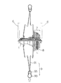
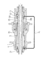
本発明を実施するための形態について、図1ないし図4を基に説明する。本実施の形態にかかるものは、図1に示す如く、二又状のフォーク6のところに取付けられるものであって、車輪を形成するタイヤ99またはリム95等からの荷重がスポーク91を介して入力されるとともに、チェーン8を介して伝達される回転駆動力を車輪9に伝達する役目を果たすギヤ7の取付けられる自転車用リアハブ装置に関するものである。具体的には、図1ないし図4に示す如く、車輪9の中心部に設けられるものであってタイヤ99の取付けられるリム95からの入力荷重をスポーク91を介して受けるハブケース1と、当該ハブケース1の内径側に設けられるものであって、後に述べるベアリングを保持する円筒状の形態からなるベアリングホルダ3と、当該ベアリングホルダ3に伝達されたハブケース1からの入力荷重を後に述べるシャフト5側へ伝達する役目を果たすとともに、上記ハブケース1を含む車輪全体を回転自在なように支持する第一のベアリング31及び第二のベアリング32と、これら第一のベアリング31及び第二のベアリング32を介して上記車輪9全体を回転自在なように支持するものであって、上記ハブケース1の幅の値よりも大きく形成された延長部55を有するシャフト5と、からなることを基本とするものである。
An embodiment for carrying out the present invention will be described with reference to FIGS. As shown in FIG. 1, the present embodiment is attached to a bifurcated
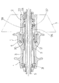
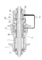
このような基本構成からなるものにおいて、上記シャフト5の延長部55のところには、図2に示す如く、シャフト5の延長部55の外周側に上記ベアリングホルダ3の一部を形成する突出部39が設けられるようになっている。そして、このような突出部39の先端部のところには上記第一のベアリング31または第二のベアリング32のうちのいずれか一方のもの(本実施の形態においては第二のベアリング32)が設けられるようになっている。そして、このような突出部39の外周側のところには、ギヤ7の取付けられる円筒状の部材からなるものであって、その一方の端部21側は上記ハブケース1内に収容された状態で、その内径側は上記ハブケース1内に設けられたベアリングホルダ3の外径側にニードルベアリングまたは薄肉形ボールベアリングを含む第四のベアリング35を介して取付けられる駆動軸2が設けられるようになっている。そして、このような駆動軸2の上記ハブケース1内に収納される部分の、その外側には複数のラチェット爪4が設けられるようになっている。そして更に、このような駆動軸2のもう一方の端部22側のところであって、上記第一のベアリング31または第二のベアリング32の、いずれか一方のベアリング(本実施の形態においては第二のベアリング32)よりも外側のところには第三のベアリング33が設けられるようになっている。そして、上記駆動軸2はシャフト5の延長部55のところに回転自在なように取付けられるとともに、上記ハブケース1とはラチェット爪4を介してギヤ7側からの回転駆動力を円滑に伝達することができるように取付けられている。すなわち、本実施の形態のものにおいては、リアハブ全体の構造が二重軸構造となっているものである。
In such a basic structure, the
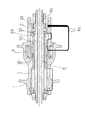
このような構成を採ることにより、本実施の形態のものにおいては、主に車輪9側から入力される荷重(P1)に対しては、例えば図3に示す如く、まず、ハブケース1に入力されるとともに、この荷重(力)は、ハブケース1内に設けられたベアリングホルダ3を介して、当該ベアリングホルダ3の両端部に設けられた第一のベアリング31及び第二のベアリング32のところへと伝達される。すなわち、本実施の形態のものにおいては、入力荷重をハブケース1内に設けられたベアリングホルダ3の両端部にて左右均等な状態で受止めることができるようになっている。そして、これら両ベアリング31、32のところに伝達された荷重(力)は当該両ベアリング31、32の取付点を介してシャフト5へと伝達されることとなる。ところで、本実施の形態のものにおいては、上記両ベアリング31、32の取付間隔は、車輪を形成するハブケース1の幅の値よりも大きく(拡く)採られていることより、上記荷重(力)は分散された状態でベアリング31、32及びシャフト1へと伝達されることとなる。従って、各ベアリング31、32を介して入力されるシャフト1への負荷は軽減化されることとなり、シャフト1の両ベアリング31、32を介しての回転運動は常に円滑に保持されることとなる。
By adopting such a configuration, in the present embodiment, the load (P 1 ) input mainly from the
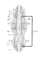
また、本実施の形態のものにおいては、ギヤ7を介して入力される駆動力に基づく荷重(P2)は、例えば図4に示す如く、ギヤ7を保持する駆動軸2が一方の端部(本実施の形態のものにおいては外側の端部)側に設けられた第三のベアリング33と、ハブケース1内の駆動軸2の取付けられる端部側に設けられたニードルベアリングまたは薄肉形ボールベアリング等からなる第四のベアリング35とによって支持されるようになっている。従って、本実施の形態のものにおいては、上記駆動力に基づく荷重(P2)は上記二つのベアリング33、35を介してハブケース1側へと円滑に伝達されることとなる。従って、ハブケース1から横へ張出すように取り付けられる駆動軸2側からの荷重(負荷)に対しては、本実施の形態のものにおいては、これを確実に保持することができるようになり、ギヤ7からの駆動力を円滑に車輪9側へと伝達することができるようになる。
Further, in the present embodiment, the load (P 2 ) based on the driving force input via the
1 ハブケース
2 駆動軸
21 端部
22 端部
3 ベアリングホルダ
31 第一のベアリング
32 第二のベアリング
33 第三のベアリング
35 第四のベアリング
39 突出部
4 ラチェット爪
5 シャフト
55 延長部
6 フォーク
7 ギヤ
8 チェーン
9 車輪
91 スポーク
95 リム
99 タイヤ
DESCRIPTION OF
Claims (2)
2. The bicycle rear hub device according to claim 1, wherein a bearing holder that is provided on an inner diameter side of the hub case and holds the first bearing and the second bearing is disposed at one end thereof and the gear. An end portion formed on the side to be attached is projected to the drive shaft side so as to have a projecting portion, and the first bearing or the second bearing is provided at the tip of the projecting portion. A bicycle rear hub device characterized in that any one of the bearings is provided.
Priority Applications (1)
| Application Number | Priority Date | Filing Date | Title |
|---|---|---|---|
| JP2011003561A JP5406227B2 (en) | 2011-01-12 | 2011-01-12 | Bicycle rear hub device |
Applications Claiming Priority (1)
| Application Number | Priority Date | Filing Date | Title |
|---|---|---|---|
| JP2011003561A JP5406227B2 (en) | 2011-01-12 | 2011-01-12 | Bicycle rear hub device |
Publications (2)
| Publication Number | Publication Date |
|---|---|
| JP2012144136A true JP2012144136A (en) | 2012-08-02 |
| JP5406227B2 JP5406227B2 (en) | 2014-02-05 |
Family
ID=46788184
Family Applications (1)
| Application Number | Title | Priority Date | Filing Date |
|---|---|---|---|
| JP2011003561A Active JP5406227B2 (en) | 2011-01-12 | 2011-01-12 | Bicycle rear hub device |
Country Status (1)
| Country | Link |
|---|---|
| JP (1) | JP5406227B2 (en) |
Cited By (1)
| Publication number | Priority date | Publication date | Assignee | Title |
|---|---|---|---|---|
| WO2013114779A1 (en) * | 2012-02-03 | 2013-08-08 | 株式会社近藤機械製作所 | Bicycle hub unit |
Citations (2)
| Publication number | Priority date | Publication date | Assignee | Title |
|---|---|---|---|---|
| JPH09210101A (en) * | 1996-02-02 | 1997-08-12 | Shimano Inc | Ratchet noise silencing mechanism for freewheel of a bicycle |
| JP2000025674A (en) * | 1998-07-14 | 2000-01-25 | Sugino Techno:Kk | Multistage sprocket device for bicycle |
-
2011
- 2011-01-12 JP JP2011003561A patent/JP5406227B2/en active Active
Patent Citations (2)
| Publication number | Priority date | Publication date | Assignee | Title |
|---|---|---|---|---|
| JPH09210101A (en) * | 1996-02-02 | 1997-08-12 | Shimano Inc | Ratchet noise silencing mechanism for freewheel of a bicycle |
| JP2000025674A (en) * | 1998-07-14 | 2000-01-25 | Sugino Techno:Kk | Multistage sprocket device for bicycle |
Cited By (2)
| Publication number | Priority date | Publication date | Assignee | Title |
|---|---|---|---|---|
| WO2013114779A1 (en) * | 2012-02-03 | 2013-08-08 | 株式会社近藤機械製作所 | Bicycle hub unit |
| JP2013159189A (en) * | 2012-02-03 | 2013-08-19 | Kondo Kikai Seisakusho:Kk | Bicycle hub unit |
Also Published As
| Publication number | Publication date |
|---|---|
| JP5406227B2 (en) | 2014-02-05 |
Similar Documents
| Publication | Publication Date | Title |
|---|---|---|
| CN102079360B (en) | Bicycle chainwheel supporting component | |
| JP5778740B2 (en) | Omnidirectional moving wheel and omnidirectional moving vehicle equipped with the same | |
| JP6109963B2 (en) | Unicycle | |
| EP2549148B1 (en) | Planetary gear train for transmission of motor | |
| US20140014422A1 (en) | Electric forklift | |
| EP2123547A3 (en) | Inverted pendulum mobile vehicle | |
| JP2017512708A (en) | Rear wheel axle, bicycle frame and bicycle rear wheel | |
| JP5406227B2 (en) | Bicycle rear hub device | |
| JP5514303B2 (en) | Bicycle hub device | |
| KR101870441B1 (en) | Planetary Gear Train for Transmission of e-bike motor | |
| JP2009083706A (en) | Double-wheel caster | |
| JP2011152651A5 (en) | ||
| CN201144979Y (en) | Fly wheel | |
| JP6598176B1 (en) | Gear plate mounting structure on crankshaft | |
| JP2005247297A (en) | Wheel for moving body | |
| JP5947118B2 (en) | Wheel | |
| CN201901390U (en) | Installing structure of free rolling wheel of movable goods shelf | |
| CN101244681B (en) | Bicycle hub assembly | |
| JP2015182763A (en) | Driving device for front wheel drive bicycle | |
| JP2012102799A (en) | Worm reduction gear | |
| JP5745436B2 (en) | Bicycle hub device | |
| CN202541200U (en) | Combination wheel | |
| CN105766199B (en) | A kind of roller fast unloading device of combine harvester | |
| US20140312680A1 (en) | Modularized hub assembly | |
| JP2011031791A (en) | Rotational inertial force increasing member and driving wheel of bicycle having the same |
Legal Events
| Date | Code | Title | Description |
|---|---|---|---|
| A977 | Report on retrieval |
Free format text: JAPANESE INTERMEDIATE CODE: A971007 Effective date: 20130731 |
|
| A131 | Notification of reasons for refusal |
Free format text: JAPANESE INTERMEDIATE CODE: A131 Effective date: 20130802 |
|
| A521 | Request for written amendment filed |
Free format text: JAPANESE INTERMEDIATE CODE: A523 Effective date: 20130920 |
|
| TRDD | Decision of grant or rejection written | ||
| A01 | Written decision to grant a patent or to grant a registration (utility model) |
Free format text: JAPANESE INTERMEDIATE CODE: A01 Effective date: 20131028 |
|
| A61 | First payment of annual fees (during grant procedure) |
Free format text: JAPANESE INTERMEDIATE CODE: A61 Effective date: 20131031 |
|
| R150 | Certificate of patent or registration of utility model |
Ref document number: 5406227 Country of ref document: JP Free format text: JAPANESE INTERMEDIATE CODE: R150 |
|
| R250 | Receipt of annual fees |
Free format text: JAPANESE INTERMEDIATE CODE: R250 |
|
| R250 | Receipt of annual fees |
Free format text: JAPANESE INTERMEDIATE CODE: R250 |
|
| R250 | Receipt of annual fees |
Free format text: JAPANESE INTERMEDIATE CODE: R250 |
|
| R250 | Receipt of annual fees |
Free format text: JAPANESE INTERMEDIATE CODE: R250 |
|
| R250 | Receipt of annual fees |
Free format text: JAPANESE INTERMEDIATE CODE: R250 |
|
| R250 | Receipt of annual fees |
Free format text: JAPANESE INTERMEDIATE CODE: R250 |