JP2012144155A - Rear structure of vehicle - Google Patents

Rear structure of vehicle Download PDF

Info

Publication number
JP2012144155A
JP2012144155A JP2011004242A JP2011004242A JP2012144155A JP 2012144155 A JP2012144155 A JP 2012144155A JP 2011004242 A JP2011004242 A JP 2011004242A JP 2011004242 A JP2011004242 A JP 2011004242A JP 2012144155 A JP2012144155 A JP 2012144155A
Authority
JP
Japan
Prior art keywords
panel
vehicle
vehicle body
partition
wheel house
Prior art date
Legal status (The legal status is an assumption and is not a legal conclusion. Google has not performed a legal analysis and makes no representation as to the accuracy of the status listed.)
Granted
Application number
JP2011004242A
Other languages
Japanese (ja)
Other versions
JP5494500B2 (en
Inventor
Yuki Natsume
裕貴 棗
Shusuke Matsuoka
秀典 松岡
Daisuke Yamada
大輔 山田
Chie Fukuhara
千絵 福原
Daichi Kusunoki
大地 楠木
Current Assignee (The listed assignees may be inaccurate. Google has not performed a legal analysis and makes no representation or warranty as to the accuracy of the list.)
Mazda Motor Corp
Original Assignee
Mazda Motor Corp
Priority date (The priority date is an assumption and is not a legal conclusion. Google has not performed a legal analysis and makes no representation as to the accuracy of the date listed.)
Filing date
Publication date
Application filed by Mazda Motor Corp filed Critical Mazda Motor Corp
Priority to JP2011004242A priority Critical patent/JP5494500B2/en
Publication of JP2012144155A publication Critical patent/JP2012144155A/en
Application granted granted Critical
Publication of JP5494500B2 publication Critical patent/JP5494500B2/en
Expired - Fee Related legal-status Critical Current
Anticipated expiration legal-status Critical

Links

Images

Landscapes

  • Body Structure For Vehicles (AREA)

Abstract

PROBLEM TO BE SOLVED: To effectively prevent noise outside of a vehicle from intruding into a cabin from a ventilation opening arranged in a rear part of a vehicle body.SOLUTION: This rear structure of a vehicle is constituted so that air ventilation is performed via a space part along a wheel arch by first and second openings 17 and 24 formed in a fender panel 13 arranged along a side part of a luggage compartment arranged in the rear of a vehicle and a luggage compartment inside trim member 16. An opening part of becoming an air flow passage is formed in a panel member or the like positioned inside the fender panel 13, a first partition member 25 is arranged in the panel member for vertically partitioning the space part arranged between the fender panel and the panel member in the outside part of the panel member, and a second partition member 26 abutting on the first partition member 25 is arranged on the back face side of the trim member 16, and the air ventilation is performed via a lower space part 28 partitioned by the first and second partition members 25 and 26.

Description

本発明は、車両後方に設けられた荷室の側方部に沿って設置されたフェンダパネルおよび荷室内側のトリム部材を備えた車両の後部構造に関するものである。   The present invention relates to a rear structure of a vehicle including a fender panel installed along a side portion of a cargo compartment provided at the rear of the vehicle and a trim member on the cargo compartment side.

従来、下記特許文献1に示されるように、車両後部の車幅方向両側に配置されるクォータアウタパネル部材と、クォータアウタパネル部材の車幅方向内側に配置されるクォータインナパネル部材と、クォータインナパネル部材よりも後方でクォータアウタパネル部材間に接合され、一方のパネル部材から他方のパネル部材まで連続するフロア面を形成するフロアパネル部材と、フロアパネル部材の後端に接合およびクォータアウタパネル部材の後端に接合されたリヤエンドパネル部材とを有し、クォータインナパネル部材の後端からリヤエンドパネル部材までの間に、クォータアウタパネル部材で区画した荷室部を形成してなる車体後部と、荷室部をなすクォータアウタパネル部材とフロアパネル部材との接合部に沿って配置され、前端部がクォータインナパネル部材に接合され、後端部がリヤエンド部材に接合され、中間部がフロアパネル部材およびクォータアウタパネル部材と3点打点溶接で接合されてなる接合プレート部材とを有した構造とすることにより、既にあるフロアパネル部材とクォータアウタパネル部材との接合構造を流用して、クォータインナパネル部材とリヤエンドパネル部間に接合プレートを設け、車体後部の剛性強度を高めることが行われている。   Conventionally, as shown in Patent Document 1 below, a quarter outer panel member disposed on both sides in the vehicle width direction of the rear portion of the vehicle, a quarter inner panel member disposed on the inner side in the vehicle width direction of the quarter outer panel member, and a quarter inner panel member The floor panel member joined between the quarter outer panel members at the rear and forming a continuous floor surface from one panel member to the other panel member, and joined to the rear end of the floor panel member and the rear end of the quarter outer panel member A rear end panel member joined to the rear end panel member from the rear end of the quarter inner panel member to form a cargo compartment section defined by the quarter outer panel member, and a cargo compartment section. It is arranged along the joint between the quarter outer panel member and the floor panel member, and the front end is A structure having a joining plate member joined to a water inner panel member, a rear end portion joined to a rear end member, and an intermediate portion joined to a floor panel member and a quarter outer panel member by three-point spot welding. Accordingly, a joint plate between the quarter inner panel member and the rear end panel portion is provided by utilizing the existing joint structure between the floor panel member and the quarter outer panel member, and the rigidity strength of the rear portion of the vehicle body is increased.

特開2008−155714号公報JP 2008-155714 A

上記特許文献1に開示された車両の車体構造では、車両の軽量化を図るために、サイドドアパネルのうち車体後部を形成するクォータアウタパネル部の内面のうち、後輪アーチ部の付近から前方側だけに、クォータインナパネル部材を設けたセダンタイプの車両において、上記クォータアウタパネル部材とフロアパネル部材とに沿って該クォータアウタパネル部材およびフロアパネル部材とリヤエンド部材とを接合する上記接合プレート部材を設けため、簡単な構成で、荷室部のフロア高さの低下に伴う車体剛性の低下を効果的に抑制することが可能である。   In the vehicle body structure disclosed in Patent Document 1, in order to reduce the weight of the vehicle, only the front side from the vicinity of the rear wheel arch portion of the inner surface of the quarter outer panel portion that forms the rear portion of the vehicle body among the side door panels. Further, in a sedan type vehicle provided with a quarter inner panel member, in order to provide the joining plate member for joining the quarter outer panel member and the floor panel member and the rear end member along the quarter outer panel member and the floor panel member, With a simple configuration, it is possible to effectively suppress a decrease in vehicle body rigidity accompanying a decrease in the floor height of the cargo compartment.

しかし、上記車体後部の荷室部を区画するクォータアウタパネル部材に設けられたベンチレーション用開口部から後部車体内に侵入した車外の騒音が、上記クォータアウタパネルとのその内方側に配設されたトリム部材との間においてホイールアーチ沿いに形成された大きな空間部に伝播され、該空間部から車室内に上記騒音が侵入し易いという問題がある。特に、上記後部荷室と車室内部とが完全に区画された状態にないハッチバックタイプの車両では、車外の騒音が車室内に進入するのを効果的に防止することができないため、上記トリム部材の裏面の広範囲に吸音材を設置する等の手段を講じる必要があった。   However, noise outside the vehicle that has entered the rear vehicle body from the ventilation opening provided in the quarter outer panel member that defines the cargo compartment at the rear of the vehicle body is disposed on the inner side of the quarter outer panel. There is a problem that the noise is easily transmitted to a large space formed along the wheel arch between the trim member and the vehicle from the space to the vehicle interior. In particular, in a hatchback type vehicle in which the rear luggage compartment and the interior of the vehicle interior are not completely separated, noise from outside the vehicle cannot be effectively prevented from entering the interior of the vehicle. It was necessary to take measures such as installing sound-absorbing material over a wide area on the back of the machine.

本発明は、上記の問題点に鑑みてなされたものであり、車外の騒音が車体の後部に設けられたベンチレーション用の開口から車室内に侵入するのを簡単な構成で効果的に防止できる車両の後部構造を提供することを目的としている。   The present invention has been made in view of the above-described problems, and can effectively prevent noise outside the vehicle from entering the vehicle interior from a ventilation opening provided at the rear portion of the vehicle body. The object is to provide a rear structure of a vehicle.

請求項1に係る発明は、車両の後方に設けられた荷室の側方部に沿って設置されたフェンダパネルおよび荷室内側のトリム部材に形成された第1,第2開口により、ホイールアーチ沿いの空間部を経由してエアベンチレーションが行われるように構成された車両の後部構造であって、上記フェンダパネルよりも内側に位置するパネル部材、または該パネル部材と車体後壁部との間にエアの流通路となる開口部が形成されるとともに、上記パネル部材には、その外方側部において上記フェンダパネルとの間に設けられた空間部を上下に区画する第1仕切部材が設けられ、かつ上記トリム部材の背面側には第1仕切部材と当接する第2仕切部材が設けられ、該第1,第2仕切部材により区画された下方の空間部を介してエアベンチレーションが行われるように構成されたものである。   According to a first aspect of the present invention, a wheel arch is formed by a fender panel installed along a side portion of a cargo compartment provided at the rear of a vehicle and first and second openings formed in a trim member on the cargo compartment side. A rear structure of a vehicle configured to perform air ventilation via a space along the side wall, the panel member positioned inside the fender panel, or the panel member and the vehicle body rear wall An opening serving as an air flow passage is formed therebetween, and the panel member includes a first partition member that vertically divides a space provided between the panel member and the fender panel on an outer side thereof. And a second partition member that contacts the first partition member is provided on the back side of the trim member, and air ventilation is performed through a lower space defined by the first and second partition members. line Those that are configured to be.

請求項2に係る発明は、上記請求項1に記載の車両の後部構造において、第1仕切部材が、上記パネル部材に設けられた保持部材と、該保持部材に取り付けられた熱発泡性樹脂材からなるシート部材とを有し、該シート部材が車体の塗装乾燥工程で加熱されて発泡することにより上記フェンダパネルおよびパネル部材に密着した状態となるよう構成されたものである。   The invention according to claim 2 is the rear structure of the vehicle according to claim 1, wherein the first partition member is a holding member provided on the panel member, and a thermally foamable resin material attached to the holding member. The sheet member is configured to be in close contact with the fender panel and the panel member when the sheet member is heated and foamed in the paint drying process of the vehicle body.

請求項3に係る発明は、上記請求項1または2に記載の車両の後部構造において、第2仕切部材が、上記トリム部材の裏面側に取り付けられるとともに、上記保持部材の内側面に密着する帯状弾性体を備えたものである。   According to a third aspect of the present invention, in the rear structure of the vehicle according to the first or second aspect, the second partition member is attached to the back surface side of the trim member and is in a belt-like shape that is in close contact with the inner side surface of the holding member. An elastic body is provided.

請求項4に係る発明は、上記請求項1〜3のいずれか1項に記載の車両の後部構造において、帯状弾性体が、上記保持部材の内側面に密着する横長部分と、その一端側に連続して上記パネル部材に密着する縦長部分とを備えたものである。   According to a fourth aspect of the present invention, in the rear structure of the vehicle according to any one of the first to third aspects of the present invention, the belt-like elastic body has a horizontally long portion that is in close contact with the inner surface of the holding member, and one end thereof. And a vertically long portion that is in close contact with the panel member.

請求項5に係る発明は、上記請求項1〜3のいずれか1項に記載の車両の後部構造において、車体の後部にバックドアが開閉可能に設置された後方開口部と、その周辺部に沿って設置された車体後壁部とを有するとともに、上記パネル部材としてのホイールハウスアウタパネルの後端部が上記車体後壁部の側辺部と所定距離を置いてその前方側に配設されることにより、上記ホイールハウスアウタパネルの後端部と車体後壁部の側辺部との間にエアの流通路となる開口部が形成され、かつ上記ホイールハウスアウタパネルの後端部と車体後壁部の側辺部との間に上記第1仕切部材が設置されたものである。   According to a fifth aspect of the present invention, in the rear structure of the vehicle according to any one of the first to third aspects, a rear opening portion in which a back door can be opened and closed at the rear portion of the vehicle body, and a peripheral portion thereof. And a rear end portion of the wheel house outer panel as the panel member is disposed on the front side of the side portion of the vehicle body rear wall portion at a predetermined distance. As a result, an opening serving as an air flow path is formed between the rear end portion of the wheel house outer panel and the side portion of the vehicle body rear wall portion, and the rear end portion of the wheel house outer panel and the vehicle body rear wall portion. The said 1st partition member is installed between these side parts.

請求項1に係る発明では、上記第1仕切部材および第2仕切部材を介して車体側壁部に形成された大容量の空間部を上下に区画してエアベンチレーションが行われるように構成したため、例えばサイドドアの閉止時に、上記トリム部材の第2開口から上記空間部内に流入した空気を上記エア流通用の開口部とフェンダパネルに形成された第1開口とを介して車外に排出させることができ、上記サイドドアの閉止時等に、車室内の圧力が上昇することに起因して乗員が不快感を受けることを効果的に防止できるという利点がある。そして、上記フェンダパネルの第1開口から車体側壁部に侵入した車外の騒音が、ホイールアーチ沿いにその上方の空間部に伝達されるのを上記第1仕切部材および第2仕切部材により効果的に防止することができるため、上記トリム部材の裏面の広範囲に吸音材を設置する等の手段を講じることなく、上記車外の騒音が車室内に進入するのを簡単な構成で効果的に防止することができる。   In the invention according to claim 1, since the large volume space formed in the side wall portion of the vehicle body is vertically divided via the first partition member and the second partition member, the air ventilation is performed. For example, when the side door is closed, the air flowing into the space from the second opening of the trim member can be discharged outside the vehicle through the opening for air circulation and the first opening formed in the fender panel. In addition, there is an advantage that it is possible to effectively prevent a passenger from feeling uncomfortable due to an increase in pressure in the passenger compartment when the side door is closed. Further, the first partition member and the second partition member effectively transmit noise outside the vehicle that has entered the vehicle body side wall from the first opening of the fender panel to the space above the wheel arch. Therefore, it is possible to effectively prevent noise outside the vehicle from entering the vehicle interior without taking measures such as installing a sound absorbing material over a wide range of the back surface of the trim member. Can do.

請求項2に係る発明では、ホイールハウスアウタパネル等からなるパネル部材に設けられた保持部材と、該保持部材に取り付けられた熱発泡性樹脂材からなるシート部材とにより上記第1仕切部材を構成し、上記シート部材を車体の塗装乾燥工程で加熱して発泡させることによりフェンダパネルおよび上記パネル部材に密着させるよう構成したため、該フェンダパネルおよびパネル部材が複雑な形状を有する場合においても、上記塗装乾燥工程の熱を利用して該パネル部材等に上記シート部材を確実に密着させることができ、上記シート部材を有する第1仕切部材を利用して車体側壁部に形成された大容量の空間部を適正に区画できるという利点がある。   In the invention which concerns on Claim 2, the said 1st partition member is comprised by the holding member provided in the panel member which consists of a wheel house outer panel etc., and the sheet | seat member which consists of a thermally foamable resin material attached to this holding member. Since the sheet member is heated and foamed in the paint drying process of the vehicle body to be in close contact with the fender panel and the panel member, the paint drying is performed even when the fender panel and the panel member have a complicated shape. The sheet member can be securely adhered to the panel member or the like using the heat of the process, and the large-capacity space formed on the vehicle body side wall using the first partition member having the sheet member There is an advantage that it can be properly partitioned.

請求項3に係る発明では、トリム部材の裏面側に取り付けられた帯状弾性体により上記第2仕切部材を構成したため、該帯状弾性体をトリム部材に取り付けた状態で、これらを一体的に車体へ組み付けることができる。また、上記トリム部材および第1,第2仕切部材の形状精度やその取付位置にバラツキがあっても、上記帯状弾性体と第1仕切部材を構成する上記保持部材とをピッタリと密着させた状態で設置することができるため、第1,第2仕切部材により上記空間部を効果的に区画できるという利点もある。   In the invention according to claim 3, since the second partition member is constituted by the belt-like elastic body attached to the back surface side of the trim member, the belt-like elastic body is integrally attached to the vehicle body in a state where the belt-like elastic body is attached to the trim member. Can be assembled. In addition, even when the shape accuracy of the trim member and the first and second partition members and the mounting positions thereof vary, the belt-like elastic body and the holding member constituting the first partition member are in close contact with each other. Therefore, there is also an advantage that the space can be effectively partitioned by the first and second partition members.

請求項4に係る発明では、上記第2仕切部材の帯状弾性体を、保持部材の内側面に密着する横長部分と、その一端側に連続してホイールハウスアウタパネル等からなるパネル部材に密着する縦長部分とにより構成したため、該縦長部分により上記トリム部材とパネル部材との間を適正にシールして上記第1,第2仕切部材による仕切機能を充分に満足できるものとすることができる。   In the invention which concerns on Claim 4, the strip-shaped elastic body of the said 2nd partition member is the elongate part closely_contact | adhered to the panel member which consists of a horizontally long part closely_contact | adhered to the inner surface of a holding member, and its one end side, etc. Therefore, the vertically long portion can adequately seal the space between the trim member and the panel member to sufficiently satisfy the partition function of the first and second partition members.

請求項5に係る発明では、車体の後部にバックドアが開閉可能に設置された後方開口部と、その周辺部に沿って設置された車体後壁部とを有する車両の後部構造において、上記ホイールハウスアウタパネルの後端部を上記車体後壁部の側辺部と所定距離を置いてその前方側に配設することにより、上記ホイールハウスアウタパネルの後端部と車体後壁部の側辺部との間にエアの流通路となる開口部を形成し、かつ上記ホイールハウスアウタパネルの後端部と車体後壁部の側辺部との間に上記第1仕切部材を設置したため、車体重量を効果的に低減しつつ、上記開口部を介してエアベンチレーション機能を充分に確保することができ、かつ上記フェンダパネルに形成された第1開口から車体側壁部に侵入した車外の騒音がホイールアーチ沿いに上記空間部の上方に伝播するのを効果的に防止できるという利点がある。   In the invention according to claim 5, in the rear structure of the vehicle having a rear opening portion in which a back door is installed at the rear portion of the vehicle body so as to be openable and closable, and a vehicle body rear wall portion installed along the periphery thereof, the wheel By disposing the rear end portion of the house outer panel at a predetermined distance from the side portion of the vehicle body rear wall portion, the rear end portion of the wheel house outer panel and the side portion of the vehicle body rear wall portion are arranged. The first partition member is installed between the rear end of the wheel house outer panel and the side of the rear wall of the vehicle body, so that the weight of the vehicle body is effective. The air ventilation function can be sufficiently ensured through the opening while reducing the noise, and noise outside the vehicle that has entered the vehicle body side wall from the first opening formed in the fender panel is along the wheel arch. In There is an advantage that the propagation over the serial space can be effectively prevented.

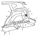
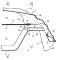
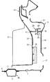
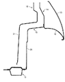
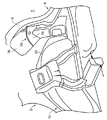
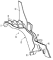
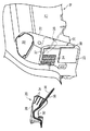
本発明に係る車両の後部構造の実施形態を示す斜視図である。1 is a perspective view showing an embodiment of a rear structure of a vehicle according to the present invention. 上記車両の後部構造の具体的構成を示す平面断面図である。FIG. 2 is a plan sectional view showing a specific configuration of the rear structure of the vehicle. 図2のIII−III線断面図である。It is the III-III sectional view taken on the line of FIG. 図2のIV−IV線断面図である。It is the IV-IV sectional view taken on the line of FIG. トリム部材を取り外した状態を示す図1相当図である。FIG. 2 is a view corresponding to FIG. 1 showing a state where a trim member is removed. 第1仕切部材の具体的構成を示す斜視図である。It is a perspective view which shows the specific structure of a 1st partition member. 第2仕切部材をトリム部材に取り付けた状態を示す斜視図である。It is a perspective view which shows the state which attached the 2nd partition member to the trim member.

図1〜図5は、本発明に係る車両の後部構造の実施形態を示している。該車両は、車体の底面部を構成するフロアパネル1と、車体の後部に設けられた荷室2と、その側方部に沿って設置された車体側壁部3と、車体の後端部に設けられた車体後壁部4とを有している。該車体後壁部4には、図略のバックドアが開閉可能に設置された後方開口部5の側辺部に沿って上下方向に延びるリヤピラー6が設けられている。上記フロアパネル1は、乗員用シート(図示せず)が設置される車室内フロア部7と、その後方に設けられたリヤフロア部8とを具備し、該リヤフロア部8の上方に上記荷室2が形成されている。   1 to 5 show an embodiment of a rear structure of a vehicle according to the present invention. The vehicle includes a floor panel 1 constituting a bottom portion of the vehicle body, a luggage compartment 2 provided at the rear portion of the vehicle body, a vehicle body side wall portion 3 installed along a side portion thereof, and a rear end portion of the vehicle body. The vehicle body rear wall portion 4 is provided. The vehicle body rear wall portion 4 is provided with a rear pillar 6 extending in the vertical direction along a side portion of a rear opening 5 in which a back door (not shown) is installed so as to be opened and closed. The floor panel 1 includes a vehicle interior floor portion 7 on which an occupant seat (not shown) is installed, and a rear floor portion 8 provided behind the vehicle interior floor portion 7, and the cargo compartment 2 above the rear floor portion 8. Is formed.

上記リヤフロア部8の左右両側辺部には、リヤサイドフレーム10が車両の前後方向に延びるように設置されている。図3に示すように、該リヤサイドフレーム10は、フロアパネル1の上方へ膨出した段部を形成する上側部材11と、フロアパネル1の下方に凹入した断面コ字状部を有する下側部材12とを有し、これらの上側部材11および下側部材12により車両の前後方向に延びる閉断面がそれぞれ形成されている。   Rear side frames 10 are installed on the left and right side portions of the rear floor portion 8 so as to extend in the front-rear direction of the vehicle. As shown in FIG. 3, the rear side frame 10 includes an upper member 11 that forms a stepped portion that bulges upward from the floor panel 1, and a lower side that has a U-shaped section that is recessed below the floor panel 1. Each of the upper member 11 and the lower member 12 forms a closed cross section that extends in the front-rear direction of the vehicle.

上記車体側壁部3は、図3および図4に示すように、車体の外側壁を構成するフェンダパネル13と、その車幅方向内方側に配設されたホイールハウスアウタパネル14およびホイールハウスインナパネル15とを有し、該ホイールハウスインナパネル15の荷室内側にはトリム部材16が所定距離を置いて配設されている。上記フェンダパネル13の後部下方には、エアベンチレーション用の第1開口17が、図示を省略したリヤバンパの側端部により覆われる位置に形成されている。   As shown in FIGS. 3 and 4, the vehicle body side wall portion 3 includes a fender panel 13 constituting an outer wall of the vehicle body, a wheel house outer panel 14 and a wheel house inner panel disposed on the inner side in the vehicle width direction. 15, and a trim member 16 is disposed at a predetermined distance on the inner side of the wheel house inner panel 15. Below the rear part of the fender panel 13, a first opening 17 for air ventilation is formed at a position covered by a side end part of a rear bumper (not shown).

上記ホイールハウスアウタパネル14には、リヤホイールの収容部となる第1膨出部18が車外側に向けて突設されている。そして、上記ホイールハウスアウタパネル14の後端部が、上記車体後壁部4のリヤピラー6と所定距離を置いてその前方側に配設されることにより、上記ホイールハウスアウタパネル14の後端部と車体後壁部4のリヤピラー6との間に、エアの流通路となる開口部19が形成されている(図5参照)。   The wheel house outer panel 14 has a first bulging portion 18 serving as a rear wheel housing portion protruding toward the vehicle exterior side. The rear end portion of the wheel house outer panel 14 is disposed on the front side of the rear pillar 6 of the vehicle body rear wall portion 4 at a predetermined distance, whereby the rear end portion of the wheel house outer panel 14 and the vehicle body are arranged. An opening 19 serving as an air flow path is formed between the rear wall 4 and the rear pillar 6 (see FIG. 5).

上記ホイールハウスインナパネル15には、リヤホイールの収容部となる第2膨出部20が車内側に向けて突設されている。また、上記ホイールハウスインナパネル15の後端部は、上記ホイールハウスアウタパネル14と同様に、車体後壁部4のリヤピラー6と所定距離を置いてその前方側に配設されている。   The wheel house inner panel 15 is provided with a second bulging portion 20 serving as a rear wheel housing portion protruding toward the vehicle interior side. Further, like the wheel house outer panel 14, the rear end portion of the wheel house inner panel 15 is disposed on the front side of the rear pillar 6 of the vehicle body rear wall portion 4 at a predetermined distance.

上記トリム部材16には、ホイールハウスインナパネル15の第2膨出部20と所定距離を置いてその車内側面部を覆うように車内側に突出した膨出部21が形成されている。また、上記トリム部材16の後部には、図1〜図3に示すように、ホイールハウスアウタパネル14の後端部と車体後壁部4との間に形成されたエア流通用の開口部19に沿って車外側に凹入した凹入部22が設けられている。   The trim member 16 is formed with a bulging portion 21 that protrudes inward of the vehicle so as to cover the inner side surface portion of the wheel house inner panel 15 at a predetermined distance from the second bulging portion 20. Further, as shown in FIGS. 1 to 3, the trim member 16 has an opening 19 for air circulation formed between the rear end portion of the wheel house outer panel 14 and the rear wall portion 4 of the vehicle body. A recessed portion 22 is provided along the outside of the vehicle.

上記凹入部22には、ホイールハウスアウタパネル14と車体後壁部4との間に形成された上記開口部19を介して上記フェンダパネル13の第1開口17に対向する位置に吸音材23が設けられるとともに、その上方にエアベンチレーション用の第2開口24が形成されている(図3参照)。これにより、上記ホイールハウスアウタパネル14の第1膨出部18と、ホイールハウスインナパネル15の第2膨出部20とからなるホイールアーチ沿いの空間部を介してエアベンチレーションが行われるようになっている。   The recessed portion 22 is provided with a sound absorbing material 23 at a position facing the first opening 17 of the fender panel 13 through the opening 19 formed between the wheel house outer panel 14 and the vehicle body rear wall portion 4. In addition, a second opening 24 for air ventilation is formed above (see FIG. 3). As a result, air ventilation is performed through a space portion along the wheel arch composed of the first bulging portion 18 of the wheel house outer panel 14 and the second bulging portion 20 of the wheel house inner panel 15. ing.

上記ホイールハウスアウタパネル14には、その外方側部において上記フェンダパネル13との間に設けられた空間部を上下に区画する第1仕切部材25が設けられている。また、上記トリム部材16の背面側には、第1仕切部材25と当接する第2仕切部材26が設けられている。そして、上記第1,第2仕切部材25,26によりフェンダパネル13とトリム部材16との間が上下の空間部27,28に区画され、該下方の空間部28を経由してエアベンチレーションが行われるように構成されている。   The wheel house outer panel 14 is provided with a first partition member 25 that vertically divides a space provided between the wheel house outer panel 14 and the fender panel 13 on the outer side. A second partition member 26 that contacts the first partition member 25 is provided on the back side of the trim member 16. The first and second partition members 25 and 26 divide the fender panel 13 and the trim member 16 into upper and lower space portions 27 and 28, and air ventilation is performed via the lower space portion 28. Configured to be done.

上記第1仕切部材25は、ホイールハウスアウタパネル14に取り付けられる合成樹脂製のブラケットからなる保持部材29と、該保持部材29に取り付けられた熱発泡性樹脂材からなるシート部材30とを有している。上記第1仕切部材25の保持部材29は、図6および図7に示すように、前端部に設けられた固定部31と、該固定部31から車体の後方側に延びる所定幅の縦壁部32と、該縦壁部32の後端に設けられた断面コ字状部の係止部33とを有している。   The first partition member 25 includes a holding member 29 made of a synthetic resin bracket attached to the wheel house outer panel 14, and a sheet member 30 made of a thermally foamable resin material attached to the holding member 29. Yes. As shown in FIGS. 6 and 7, the holding member 29 of the first partition member 25 includes a fixing portion 31 provided at the front end portion, and a vertical wall portion having a predetermined width extending from the fixing portion 31 to the rear side of the vehicle body. 32 and a locking portion 33 having a U-shaped cross section provided at the rear end of the vertical wall portion 32.

また、上記保持部材29の縦壁部32には、補強用リブ34と、上記シート部材30の取付板35とが車外側に向けて突設され、該取付板35の上面にシート部材30が接着される等により固定されている。そして、上記保持部材29の固定部31がホイールハウスアウタパネル14の後辺部にボルト止めされるとともに、車体後壁部4のリヤピラー6に設けられたフランジ部に上記係止部33が外嵌されて係止されることにより、上記保持部材29が車体側壁部3に取り付けられるように構成されている(図3および図5参照)。   Further, a reinforcing rib 34 and a mounting plate 35 of the seat member 30 are provided on the vertical wall portion 32 of the holding member 29 so as to protrude toward the vehicle exterior side, and the seat member 30 is provided on the upper surface of the mounting plate 35. It is fixed by bonding. The fixing portion 31 of the holding member 29 is bolted to the rear side portion of the wheel house outer panel 14, and the locking portion 33 is fitted on the flange portion provided on the rear pillar 6 of the vehicle body rear wall portion 4. Thus, the holding member 29 is configured to be attached to the vehicle body side wall 3 (see FIGS. 3 and 5).

上記保持部材29が車体側壁部3に取り付けられた状態で車体の塗装乾燥部に搬入され、上記取付板35に固定されたシート部材30が所定温度に加熱されて発泡することにより、図3に破線で示す状態から実線で示すように、上記シート部材30が膨張するように構成されている。これにより該シート部材30がフェンダパネル13の車内側面に密着した状態となるとともに、上記ホイールハウスアウタパネル14からなるパネル部材、具体的には上記リヤホイールの収容部となる第1膨出部18および上記リヤピラー6の外側面に密着した状態となる。   When the holding member 29 is attached to the vehicle body side wall 3 and is carried into the paint drying section of the vehicle body, and the sheet member 30 fixed to the attachment plate 35 is heated to a predetermined temperature and foamed, FIG. As shown by the solid line from the state shown by the broken line, the sheet member 30 is configured to expand. As a result, the seat member 30 comes into close contact with the vehicle interior side surface of the fender panel 13, and the panel member formed of the wheel house outer panel 14, specifically, the first bulging portion 18 serving as a housing portion for the rear wheel, and The rear pillar 6 is in close contact with the outer surface.

上記第2仕切部材26は、トリム部材16の裏面から車外側に向けて突設された取付板40と、その先端面に取り付けられた合成ゴム製の帯状弾性体36とからなっている。該帯状弾性体36は、その先端部が上記保持部材29の内側面に圧接されて密着した状態となる横長部分37と、その後端側に連続して下方側に延びるとともに、その先端部が上記ホイールハウスアウタパネル14からなるパネル部材、具体的には上記リヤホイールの収容部となる第2膨出部20に圧接されて密着した状態となる縦長部分38とにより構成されている。なお、上記トリム部材16の後部に設けられた凹入部22の上面には、図7に示すように、リヤコンビランプ(図示せず)のメンテナンスを行うための開口部39が形成され、該開口部39には図外のカバー部材が着脱可能に係止されるようなっている。   The second partition member 26 includes a mounting plate 40 projecting from the back surface of the trim member 16 toward the vehicle exterior side, and a synthetic rubber belt-like elastic body 36 attached to the front end surface of the mounting plate 40. The belt-like elastic body 36 has a horizontally elongated portion 37 whose tip end is in close contact with the inner side surface of the holding member 29 and a rear end side continuously extending downward, and its tip portion is It is comprised by the panel member which consists of the wheel house outer panel 14, specifically, the vertically long part 38 which will be in the state which press-contacted and contact | adhered to the 2nd bulging part 20 used as the accommodating part of the said rear wheel. As shown in FIG. 7, an opening 39 for performing maintenance of a rear combination lamp (not shown) is formed on the upper surface of the recessed portion 22 provided at the rear portion of the trim member 16, and the opening A cover member (not shown) is detachably locked to the portion 39.

上記のように車両の後方に設けられた荷室2の側方部に沿って設置されたフェンダパネル13および荷室内側のトリム部材16に形成された第1,第2開口17,24により、ホイールアーチ沿いの空間部を経由してエアベンチレーションが行われるように構成された車両の後部構造であって、上記フェンダパネル13よりも内側に位置するホイールハウスアウタパネル14等からなるパネル部材、または該パネル部材と車体後壁部4との間にエアの流通路となる開口部19が形成されるとともに、上記パネル部材には、その外方側部において上記フェンダパネル13との間に設けられた空間部を上下に区画する第1仕切部材25が設けられ、かつ上記トリム部材16の背面側には第1仕切部材25と当接する第2仕切部材26が設けられ、該第1,第2仕切部材25,26により区画された下方の空間部28を介してエアベンチレーションが行われるように構成したため、車外の騒音が車体の後部に設けられたベンチレーション用の開口から車室内に侵入するのを簡単な構成で効果的に防止できるという利点がある。   As described above, the first and second openings 17 and 24 formed in the fender panel 13 installed along the side portion of the cargo compartment 2 provided at the rear of the vehicle and the trim member 16 on the cargo compartment side, A rear structure of the vehicle configured to perform air ventilation via a space along the wheel arch, and a panel member formed of the wheel house outer panel 14 or the like positioned inside the fender panel 13; or An opening 19 serving as an air flow passage is formed between the panel member and the vehicle body rear wall 4, and the panel member is provided between the fender panel 13 on the outer side thereof. A first partition member 25 that divides the space portion up and down is provided, and a second partition member 26 that contacts the first partition member 25 is provided on the back side of the trim member 16. Since air ventilation is performed via the lower space 28 defined by the first and second partition members 25 and 26, noise outside the vehicle is generated from the ventilation opening provided at the rear of the vehicle body. There is an advantage that it is possible to effectively prevent entry into the passenger compartment with a simple configuration.

すなわち、上記実施形態では、車体の後部にバックドアが開閉可能に設置された後方開口部5と、その周辺部に沿って設置された車体側壁部3を構成するリヤピラー6とが設けられたいわゆるハッチバックタイプの車両において、ホイールハウスアウタパネル14の後端部を上記車体後壁部4の側辺部、つまり上記リヤピラー6の前方側に配設して、上記ホイールハウスアウタパネル14の後端部とリヤピラー6との間にエアの流通路となる開口部19を形成し、上記第1仕切部材25の前端部をホイールハウスアウタパネル14の後端部に支持させるとともに、上記第1仕切部材25の後端部をリヤピラー6の前面に支持させることにより、該第1仕切部材25と上記トリム部材16の背面側に設けられた第2仕切部材26とを介して、上記車体側壁部3に形成された大容量の空間部を上下に区画し(図2参照)、下方の空間部28を介してエアベンチレーションが行われるように構成したため、例えばサイドドアの閉止時に、上記トリム部材16に形成された第2開口24から該空間部28内に流入した空気を、上記エア流通用の開口部19とフェンダパネル13に形成された第1開口17とを介して車外に排出させることができる。これにより上記サイドドアの閉止時等に、車室内の圧力が上昇することに起因して乗員が不快感を受けることを効果的に防止できるという利点がある。   That is, in the above-described embodiment, a so-called rear opening 5 in which a back door can be opened and closed at the rear part of the vehicle body, and a rear pillar 6 that constitutes the vehicle body side wall part 3 installed along the periphery thereof is provided. In the hatchback type vehicle, the rear end portion of the wheel house outer panel 14 is disposed on the side portion of the vehicle body rear wall portion 4, that is, the front side of the rear pillar 6, and the rear end portion of the wheel house outer panel 14 and the rear pillar are arranged. 6, an opening 19 serving as an air flow path is formed between the front end of the first partition member 25 and the rear end of the wheel house outer panel 14, and the rear end of the first partition member 25. By supporting the portion on the front surface of the rear pillar 6, the first partition member 25 and the second partition member 26 provided on the back side of the trim member 16 are used to Since the large volume space formed in the vehicle body side wall 3 is vertically divided (see FIG. 2) and air ventilation is performed via the lower space 28, for example, when the side door is closed, Air that has flowed into the space 28 from the second opening 24 formed in the trim member 16 is brought out of the vehicle through the opening 19 for air circulation and the first opening 17 formed in the fender panel 13. It can be discharged. Accordingly, there is an advantage that it is possible to effectively prevent the occupant from feeling uncomfortable due to an increase in the pressure in the passenger compartment when the side door is closed.

そして、上記フェンダパネル13の第1開口17から車体側壁部3に侵入した車外の騒音が、上記ホイールハウスアウタパネル14の第1膨出部18およびホイールハウスインナパネル15の第2膨出部20からなるホイールアーチ沿いにその上方の空間部27に伝達されるのを、上記第1仕切部材25と第2仕切部材26により効果的に防止することができる。したがって、上記トリム部材16の裏面の広範囲に吸音材を設置する等の手段を講じることなく、例えば上記フェンダパネル13の第1開口17に対向した部分等の限られた位置に吸音材23が設けるという簡単な構成で、上記フェンダパネル13とその内方側に配設されたトリム部材16との間においてホイールアーチ沿いに形成された上方空間部27から車室内に上記車外の騒音が車室内に進入するのを効果的に防止することができる。   Then, noise outside the vehicle that has entered the vehicle body side wall portion 3 from the first opening 17 of the fender panel 13 is generated from the first bulging portion 18 of the wheel house outer panel 14 and the second bulging portion 20 of the wheel house inner panel 15. The first partition member 25 and the second partition member 26 can effectively prevent transmission along the wheel arch to the upper space 27. Therefore, for example, the sound absorbing material 23 is provided in a limited position such as a portion facing the first opening 17 of the fender panel 13 without taking a means such as installing a sound absorbing material over a wide range of the back surface of the trim member 16. With this simple configuration, noise outside the vehicle enters the vehicle interior from the upper space portion 27 formed along the wheel arch between the fender panel 13 and the trim member 16 disposed on the inner side thereof. It is possible to effectively prevent entry.

また、上記実施形態では、ホイールハウスアウタパネル14からなるパネル部材に取り付けられた保持部材29と、該保持部材29の取付板35に固定された熱発泡性樹脂材からなるシート部材30とにより第1仕切部材25を構成し、該シート部材30を車体の塗装乾燥工程で加熱して発泡させることによりフェンダパネル13およびホイールハウスアウタパネル14に密着させるよう構成したため、該フェンダパネル13およびホイールハウスアウタパネル14等からなるパネル部材が複雑な形状を有する場合においても、上記塗装乾燥工程の熱を利用して該パネル部材に上記シート部材30を確実に密着させることができる。   Moreover, in the said embodiment, it is 1st by the holding member 29 attached to the panel member which consists of the wheel house outer panel 14, and the sheet | seat member 30 which consists of a thermally foamable resin material fixed to the attachment plate 35 of this holding member 29. Since the partition member 25 is configured and the sheet member 30 is heated and foamed in the painting drying process of the vehicle body to be in close contact with the fender panel 13 and the wheel house outer panel 14, the fender panel 13 and the wheel house outer panel 14 and the like. Even when the panel member made of has a complicated shape, the sheet member 30 can be securely adhered to the panel member by utilizing the heat of the paint drying process.

したがって、上記ホイールハウスアウタパネル14等からなるパネル部材に対応した複雑な形状にシート部材30を予め形成したり、該シート部材30を上記パネル部材に密着させた状態で取り付けたりする等の繁雑な作業を要することなく、上記シート部材30を有する第1仕切部材25を利用して車体側壁部3に形成された大容量の空間部を適正に区画できるという利点がある。   Therefore, complicated work such as forming the sheet member 30 in a complicated shape corresponding to the panel member formed of the wheel house outer panel 14 or the like, or attaching the sheet member 30 in close contact with the panel member. There is an advantage that a large-capacity space portion formed in the vehicle body side wall portion 3 can be appropriately partitioned using the first partition member 25 having the sheet member 30.

また、上記実施形態に示すように、トリム部材16の裏面側に取り付けられた第2仕切部材26の帯状弾性体36を上記保持部材29の内側面に密着させるように構成した場合には、上記帯状弾性体36をトリム部材16に取り付けた状態でこれらを一体的に車体へ組み付けることができる。そして、上記トリム部材16および第1,第2仕切部材25,26の形状精度や、その取付位置にバラツキがあっても、上記第2仕切部材26の帯状弾性体36と、第1仕切部材25を構成する上記保持部材29とをピッタリと密着させた状態で設置することができるため、第1,第2仕切部材25,26により上記空間部を効果的に区画できるという利点がある。   Further, as shown in the above embodiment, when the belt-like elastic body 36 of the second partition member 26 attached to the back surface side of the trim member 16 is configured to be in close contact with the inner surface of the holding member 29, In a state where the belt-like elastic body 36 is attached to the trim member 16, these can be integrally assembled to the vehicle body. And even if the shape accuracy of the trim member 16 and the first and second partition members 25 and 26 and the mounting positions thereof vary, the belt-like elastic body 36 of the second partition member 26 and the first partition member 25. Therefore, there is an advantage that the space part can be effectively partitioned by the first and second partition members 25 and 26.

さらに、上記第2仕切部材26の帯状弾性体36を、上記保持部材29の内側面に密着する横長部分37と、その一端側に連続して上記ホイールハウスアウタパネル14からなるパネル部材に密着する縦長部分38とにより構成した場合には、該縦長部分38により上記トリム部材16とホイールハウスアウタパネル14との間を適正にシールして上記第1,第2仕切部材25,26による仕切機能を充分に満足できるものとすることができる。   Further, the belt-like elastic body 36 of the second partition member 26 is vertically long and is in close contact with a horizontally long portion 37 that is in close contact with the inner side surface of the holding member 29 and a panel member that is formed on the wheel house outer panel 14 continuously from one end thereof. In the case of being configured by the portion 38, the vertically long portion 38 properly seals the space between the trim member 16 and the wheel house outer panel 14 so that the partition function by the first and second partition members 25 and 26 is sufficiently achieved. It can be satisfactory.

また、上記実施形態では、車体の後部にバックドアが開閉可能に設置された後方開口部5と、その周辺部に沿って設置された車体後壁部4とを有するとともに、上記ホイールハウスアウタパネル14の後端部を、上記車体後壁部4のリヤピラー6からなる側辺部と所定距離を置いてその前方側に配設することにより、上記ホイールハウスアウタパネル14の後端部と車体後壁部5のリヤピラー6との間にエアの流通路となる大きな開口部19を形成したため、車体重量を効果的に低減できるとともに、上記開口部19を介してエアベンチレーション機能を充分に確保できるという利点がある。   Moreover, in the said embodiment, while having the rear opening part 5 in which the back door was installed in the rear part of the vehicle body so that opening and closing is possible, and the vehicle body rear wall part 4 installed along the periphery, the said wheel house outer panel 14 is provided. The rear end of the wheel house outer panel 14 and the rear wall portion of the vehicle body are arranged at a front side of the rear side portion of the rear wall portion 4 of the vehicle body at a predetermined distance from the side portion. Since the large opening 19 serving as an air flow passage is formed between the rear pillar 6 and the rear pillar 6, the weight of the vehicle body can be effectively reduced and the air ventilation function can be sufficiently secured through the opening 19. There is.

そして、上記ホイールハウスアウタパネル14の後端部と車体後壁部5のリヤピラー6との間に上記第1仕切部材25を設置して、ホイールハウスアウタパネル14とフェンダパネル13との間に位置する空間部を上下に区画するように構成したため、上記フェンダパネル13に形成された第1開口17から車体側壁部3に侵入した車外の騒音がホイールアーチ沿いに上記空間部の上方に伝播するのを効果的に防止することができる。   And the said 1st partition member 25 is installed between the rear-end part of the said wheel house outer panel 14, and the rear pillar 6 of the vehicle body rear wall part 5, The space located between the wheel house outer panel 14 and the fender panel 13 Since the section is divided into upper and lower parts, it is effective that noise outside the vehicle that has entered the vehicle body side wall part 3 through the first opening 17 formed in the fender panel 13 propagates above the space part along the wheel arch. Can be prevented.

なお、上記ホイールハウスアウタパネル14の後端部と車体後壁部5のリヤピラー6との間にエアの流通路となる開口部19を形成してなる上記実施形態に代え、ホイールハウスアウタパネル14の後部を切り欠くことによりエアの流通路となる開口部を形成した構造とすることも可能である。   Note that the rear portion of the wheel house outer panel 14 is replaced by the rear portion of the wheel house outer panel 14 and the rear pillar 6 of the rear wall portion 5 of the vehicle body. It is also possible to have a structure in which an opening serving as an air flow path is formed by cutting out the.

2 荷室
4 車体後壁部
13 フェンダパネル
14 ホイールハウスアウタパネル
15 ホイールハウスインナパネル
16 トリム部材
17 第1開口
19 エアの流通路となる開口部
24 第2開口
25 第1仕切部材
26 第2仕切部材
27 下方の空間部
29 保持部材
30 シート部材
37 横長部分
38 縦長部分
DESCRIPTION OF SYMBOLS 2 Cargo compartment 4 Car body rear wall part 13 Fender panel 14 Wheel house outer panel 15 Wheel house inner panel 16 Trim member 17 1st opening 19 Opening part used as air flow path 24 2nd opening 25 1st partition member 26 2nd partition member 27 Lower space 29 Holding member 30 Sheet member 37 Horizontal portion 38 Vertical portion

Claims (5)

車両の後方に設けられた荷室の側方部に沿って設置されたフェンダパネルおよび荷室内側のトリム部材に形成された第1,第2開口により、ホイールアーチ沿いの空間部を経由してエアベンチレーションが行われるように構成された車両の後部構造であって、上記フェンダパネルよりも内側に位置するパネル部材、または該パネル部材と車体後壁部との間にエアの流通路となる開口部が形成されるとともに、上記パネル部材には、その外方側部において上記フェンダパネルとの間に設けられた空間部を上下に区画する第1仕切部材が設けられ、かつ上記トリム部材の背面側には第1仕切部材と当接する第2仕切部材が設けられ、該第1,第2仕切部材により区画された下方の空間部を介してエアベンチレーションが行われるように構成されたことを特徴とする車両の後部構造。   A fender panel installed along the side of the cargo compartment provided at the rear of the vehicle and the first and second openings formed in the trim member on the cargo compartment via the space along the wheel arch A rear structure of a vehicle configured to perform air ventilation, which is a panel member positioned on the inner side of the fender panel, or an air flow path between the panel member and the rear wall portion of the vehicle body An opening is formed, and the panel member is provided with a first partition member that vertically divides a space provided between the panel member and the fender panel on the outer side thereof, and the trim member A second partition member that comes into contact with the first partition member is provided on the back side, and air ventilation is performed through a lower space defined by the first and second partition members. Rear structure of a vehicle, characterized and. 第1仕切部材が、上記パネル部材に設けられた保持部材と、該保持部材に取り付けられた熱発泡性樹脂材からなるシート部材を有し、該シート部材が車体の塗装乾燥工程で加熱されて発泡することにより上記フェンダパネルおよびパネル部材に密着した状態となるよう構成されたことを特徴とする請求項1に記載の車両の後部構造。   The first partition member has a holding member provided on the panel member and a sheet member made of a thermally foamable resin material attached to the holding member, and the sheet member is heated in a paint drying process of the vehicle body. The rear structure of a vehicle according to claim 1, wherein the rear structure of the vehicle is configured to be in close contact with the fender panel and the panel member by foaming. 第2仕切部材が、上記トリム部材の裏面側に取り付けられるとともに、上記保持部材の内側面に密着する帯状弾性体を備えたことを特徴とする請求項1または2に記載の車両の後部構造。   3. The rear structure of the vehicle according to claim 1, wherein the second partition member includes a belt-like elastic body that is attached to the back surface side of the trim member and is in close contact with the inner surface of the holding member. 帯状弾性体が、上記保持部材の内側面に密着する横長部分と、その一端側に連続して上記パネル部材に密着する縦長部分とを備えたことを特徴とする請求項1〜3のいずれか1項に記載の車両の後部構造。   The band-shaped elastic body includes a horizontally long portion that is in close contact with the inner surface of the holding member, and a vertically long portion that is continuously in contact with the panel member at one end thereof. The rear structure of the vehicle according to claim 1. 車体の後部にバックドアが開閉可能に設置された後方開口部と、その周辺部に沿って設置された車体後壁部とを有するとともに、上記パネル部材としてのホイールハウスアウタパネルの後端部が上記車体後壁部の側辺部と所定距離を置いてその前方側に配設されることにより、上記ホイールハウスアウタパネルの後端部と車体後壁部の側辺部との間にエアの流通路となる開口部が形成され、かつ上記ホイールハウスアウタパネルの後端部と車体後壁部の側辺部との間に上記第1仕切部材が設置されたことを特徴とする請求項1〜3のいずれか1項に記載の車両の後部構造。   A rear opening portion in which a back door is installed at the rear portion of the vehicle body so that it can be opened and closed, and a vehicle body rear wall portion installed along the periphery thereof, and a rear end portion of the wheel house outer panel as the panel member is An air flow path between the rear end portion of the wheel house outer panel and the side portion of the vehicle body rear wall by being disposed on the front side with a predetermined distance from the side portion of the vehicle body rear wall. The first partition member is disposed between a rear end portion of the wheel house outer panel and a side portion of the rear wall portion of the vehicle body. The rear structure of the vehicle according to any one of the preceding claims.
JP2011004242A 2011-01-12 2011-01-12 Rear structure of the vehicle Expired - Fee Related JP5494500B2 (en)

Priority Applications (1)

Application Number Priority Date Filing Date Title
JP2011004242A JP5494500B2 (en) 2011-01-12 2011-01-12 Rear structure of the vehicle

Applications Claiming Priority (1)

Application Number Priority Date Filing Date Title
JP2011004242A JP5494500B2 (en) 2011-01-12 2011-01-12 Rear structure of the vehicle

Publications (2)

Publication Number Publication Date
JP2012144155A true JP2012144155A (en) 2012-08-02
JP5494500B2 JP5494500B2 (en) 2014-05-14

Family

ID=46788201

Family Applications (1)

Application Number Title Priority Date Filing Date
JP2011004242A Expired - Fee Related JP5494500B2 (en) 2011-01-12 2011-01-12 Rear structure of the vehicle

Country Status (1)

Country Link
JP (1) JP5494500B2 (en)

Cited By (4)

* Cited by examiner, † Cited by third party
Publication number Priority date Publication date Assignee Title
JP2015024744A (en) * 2013-07-26 2015-02-05 トヨタ紡織株式会社 Exhaust structure of on-board battery
FR3020608A1 (en) * 2014-05-05 2015-11-06 Peugeot Citroen Automobiles Sa ASSEMBLY COMPRISING A BACK LATERAL TRIM FOR A MOTOR VEHICLE AND A SUPPORT THEREOF
JP2023059737A (en) * 2021-10-15 2023-04-27 株式会社イノアックコーポレーション INTERIOR MEMBER AND VEHICLE INCLUDING INTERIOR MEMBER
JP2025097642A (en) * 2023-12-19 2025-07-01 トヨタ自動車株式会社 Vehicle rear structure

Citations (4)

* Cited by examiner, † Cited by third party
Publication number Priority date Publication date Assignee Title
JPH02128684U (en) * 1989-03-31 1990-10-23
JP2004224285A (en) * 2003-01-27 2004-08-12 Mazda Motor Corp Vehicle accessory cooling structure
JP2005297759A (en) * 2004-04-12 2005-10-27 Toyota Auto Body Co Ltd Vehicular shell plate vibration damping structure and vibration damping method
JP2008155714A (en) * 2006-12-21 2008-07-10 Mitsubishi Motors Corp Vehicle body structure

Patent Citations (4)

* Cited by examiner, † Cited by third party
Publication number Priority date Publication date Assignee Title
JPH02128684U (en) * 1989-03-31 1990-10-23
JP2004224285A (en) * 2003-01-27 2004-08-12 Mazda Motor Corp Vehicle accessory cooling structure
JP2005297759A (en) * 2004-04-12 2005-10-27 Toyota Auto Body Co Ltd Vehicular shell plate vibration damping structure and vibration damping method
JP2008155714A (en) * 2006-12-21 2008-07-10 Mitsubishi Motors Corp Vehicle body structure

Cited By (5)

* Cited by examiner, † Cited by third party
Publication number Priority date Publication date Assignee Title
JP2015024744A (en) * 2013-07-26 2015-02-05 トヨタ紡織株式会社 Exhaust structure of on-board battery
FR3020608A1 (en) * 2014-05-05 2015-11-06 Peugeot Citroen Automobiles Sa ASSEMBLY COMPRISING A BACK LATERAL TRIM FOR A MOTOR VEHICLE AND A SUPPORT THEREOF
JP2023059737A (en) * 2021-10-15 2023-04-27 株式会社イノアックコーポレーション INTERIOR MEMBER AND VEHICLE INCLUDING INTERIOR MEMBER
JP7764190B2 (en) 2021-10-15 2025-11-05 株式会社イノアックコーポレーション Interior member and vehicle equipped with the interior member
JP2025097642A (en) * 2023-12-19 2025-07-01 トヨタ自動車株式会社 Vehicle rear structure

Also Published As

Publication number Publication date
JP5494500B2 (en) 2014-05-14

Similar Documents

Publication Publication Date Title
CN102133852B (en) Back door structure of a vehicle
JP6044724B2 (en) Auto body structure
JP6040644B2 (en) Vehicle side body structure
CN102963438A (en) Car body front structure for motor car
JP5494500B2 (en) Rear structure of the vehicle
JP5703145B2 (en) Vehicle front body
US9586627B2 (en) Off-road vehicle
JP2010023661A (en) Vehicle body front structure
JP6128324B2 (en) Lower body structure of the vehicle
CN109941344B (en) Vehicle front structure
CN110949543B (en) Front body structure
JP6630975B2 (en) Body front structure
JP6609824B2 (en) Vehicle front structure
JP2004224097A (en) Side body structure of vehicle
JP2016153249A (en) Vehicle rear part opening/closing panel
JP5690669B2 (en) Vehicle front body
JP6583349B2 (en) Vehicle sound absorption structure
JP6103444B2 (en) Car body
JP6057295B2 (en) Auto body structure
JP5709488B2 (en) Rear structure of the vehicle
JP5358597B2 (en) Frame structure at the rear of the body
JP6024441B2 (en) Body rear structure
CN107097853B (en) Vehicle body front structure
JP6624717B2 (en) Cowl top cover
JP6099205B2 (en) Auto body structure

Legal Events

Date Code Title Description
A621 Written request for application examination

Free format text: JAPANESE INTERMEDIATE CODE: A621

Effective date: 20130313

TRDD Decision of grant or rejection written
A977 Report on retrieval

Free format text: JAPANESE INTERMEDIATE CODE: A971007

Effective date: 20140130

A01 Written decision to grant a patent or to grant a registration (utility model)

Free format text: JAPANESE INTERMEDIATE CODE: A01

Effective date: 20140204

A61 First payment of annual fees (during grant procedure)

Free format text: JAPANESE INTERMEDIATE CODE: A61

Effective date: 20140217

R150 Certificate of patent or registration of utility model

Ref document number: 5494500

Country of ref document: JP

Free format text: JAPANESE INTERMEDIATE CODE: R150

LAPS Cancellation because of no payment of annual fees