JP2012144174A - Seat belt lock device of child car seat, and child car seat - Google Patents
Seat belt lock device of child car seat, and child car seat Download PDFInfo
- Publication number
- JP2012144174A JP2012144174A JP2011004746A JP2011004746A JP2012144174A JP 2012144174 A JP2012144174 A JP 2012144174A JP 2011004746 A JP2011004746 A JP 2011004746A JP 2011004746 A JP2011004746 A JP 2011004746A JP 2012144174 A JP2012144174 A JP 2012144174A
- Authority
- JP
- Japan
- Prior art keywords
- belt
- seat belt
- seat
- body case
- main body
- Prior art date
- Legal status (The legal status is an assumption and is not a legal conclusion. Google has not performed a legal analysis and makes no representation as to the accuracy of the status listed.)
- Granted
Links
Images


Classifications
-
- B—PERFORMING OPERATIONS; TRANSPORTING
- B60—VEHICLES IN GENERAL
- B60N—SEATS SPECIALLY ADAPTED FOR VEHICLES; VEHICLE PASSENGER ACCOMMODATION NOT OTHERWISE PROVIDED FOR
- B60N2/00—Seats specially adapted for vehicles; Arrangement or mounting of seats in vehicles
- B60N2/24—Seats specially adapted for vehicles; Arrangement or mounting of seats in vehicles for particular purposes or particular vehicles
- B60N2/26—Seats specially adapted for vehicles; Arrangement or mounting of seats in vehicles for particular purposes or particular vehicles for children
- B60N2/28—Seats readily mountable on, and dismountable from, existing seats or other parts of the vehicle
- B60N2/2803—Adaptations for seat belts
- B60N2/2806—Adaptations for seat belts for securing the child seat to the vehicle
-
- B—PERFORMING OPERATIONS; TRANSPORTING
- B60—VEHICLES IN GENERAL
- B60N—SEATS SPECIALLY ADAPTED FOR VEHICLES; VEHICLE PASSENGER ACCOMMODATION NOT OTHERWISE PROVIDED FOR
- B60N2/00—Seats specially adapted for vehicles; Arrangement or mounting of seats in vehicles
- B60N2/24—Seats specially adapted for vehicles; Arrangement or mounting of seats in vehicles for particular purposes or particular vehicles
- B60N2/26—Seats specially adapted for vehicles; Arrangement or mounting of seats in vehicles for particular purposes or particular vehicles for children
- B60N2/28—Seats readily mountable on, and dismountable from, existing seats or other parts of the vehicle
- B60N2/2803—Adaptations for seat belts
-
- B—PERFORMING OPERATIONS; TRANSPORTING
- B60—VEHICLES IN GENERAL
- B60N—SEATS SPECIALLY ADAPTED FOR VEHICLES; VEHICLE PASSENGER ACCOMMODATION NOT OTHERWISE PROVIDED FOR
- B60N2/00—Seats specially adapted for vehicles; Arrangement or mounting of seats in vehicles
- B60N2/24—Seats specially adapted for vehicles; Arrangement or mounting of seats in vehicles for particular purposes or particular vehicles
- B60N2/26—Seats specially adapted for vehicles; Arrangement or mounting of seats in vehicles for particular purposes or particular vehicles for children
- B60N2/28—Seats readily mountable on, and dismountable from, existing seats or other parts of the vehicle
- B60N2/2821—Seats readily mountable on, and dismountable from, existing seats or other parts of the vehicle having a seat and a base part
-
- B—PERFORMING OPERATIONS; TRANSPORTING
- B60—VEHICLES IN GENERAL
- B60N—SEATS SPECIALLY ADAPTED FOR VEHICLES; VEHICLE PASSENGER ACCOMMODATION NOT OTHERWISE PROVIDED FOR
- B60N2/00—Seats specially adapted for vehicles; Arrangement or mounting of seats in vehicles
- B60N2/24—Seats specially adapted for vehicles; Arrangement or mounting of seats in vehicles for particular purposes or particular vehicles
- B60N2/26—Seats specially adapted for vehicles; Arrangement or mounting of seats in vehicles for particular purposes or particular vehicles for children
- B60N2/28—Seats readily mountable on, and dismountable from, existing seats or other parts of the vehicle
- B60N2/2875—Seats readily mountable on, and dismountable from, existing seats or other parts of the vehicle inclinable, as a whole or partially
-
- B—PERFORMING OPERATIONS; TRANSPORTING
- B60—VEHICLES IN GENERAL
- B60R—VEHICLES, VEHICLE FITTINGS, OR VEHICLE PARTS, NOT OTHERWISE PROVIDED FOR
- B60R22/00—Safety belts or body harnesses in vehicles
- B60R22/12—Construction of belts or harnesses
Landscapes
- Engineering & Computer Science (AREA)
- Mechanical Engineering (AREA)
- Health & Medical Sciences (AREA)
- Child & Adolescent Psychology (AREA)
- General Health & Medical Sciences (AREA)
- Aviation & Aerospace Engineering (AREA)
- Transportation (AREA)
- Textile Engineering (AREA)
- Seats For Vehicles (AREA)
Abstract
【課題】取り付けの利便性および安定性に優れたシートベルトロック装置を提供する。
【解決手段】シートベルトロック装置21は、シートベルト挿通孔22を有する本体ケース23と、本体ケース23に支持されるベルト抜け止め部材24と、シートベルトの移動を規制するベルトロック部材25と、ベルトロック部材25を付勢する付勢手段と、第一の位置から第二の位置に移動したときに、ベルトロック部材25をベルトロック解除位置に向けて押す操作部26と、操作部26とベルト抜け止め部材24とを連動可能に連結する連結部とを備える。
【選択図】図7To provide a seat belt locking device excellent in convenience and stability of attachment.
A seat belt locking device includes a body case having a seat belt insertion hole, a belt retaining member supported by the body case, a belt locking member for restricting movement of the seat belt, An urging unit that urges the belt lock member 25; an operation unit 26 that pushes the belt lock member 25 toward the belt lock release position when the belt lock member 25 is moved from the first position to the second position; And a connecting portion for connecting the belt retaining member 24 so as to be interlocked with each other.
[Selection] Figure 7
Description
本発明は、チャイルドシートに用いられるシートベルトロック装置、およびシートベルトロック装置を備えるチャイルドシートに関するものである。 The present invention relates to a seat belt lock device used for a child seat and a child seat including the seat belt lock device.
乳幼児を自動車に乗せて移動する際に、乳幼児を着座させて用いるチャイルドシートは、自動車に設置されているシートベルトを利用して自動車の座席に締着固定される。このようなチャイルドシートにおいては、着座する乳幼児の安全を確保するために、チャイルドシートがシートベルトによって自動車の座席に堅固に固定されることが重要である。そのためには、シートベルトが、チャイルドシートの所定の位置に安定して張り渡されることが必要となる。このような安全性の観点から、シートベルトをチャイルドシートの所定の位置に保持可能とするためのシートベルトロック装置が、種々開発されてきた。このようなシートベルトロック装置として、例えば特開2001−347860号公報(特許文献1)が、開示されている。 A child seat that is used while an infant is seated when the infant moves on a car is fastened and fixed to the car seat using a seat belt installed in the car. In such a child seat, it is important that the child seat is firmly fixed to a vehicle seat by a seat belt in order to ensure the safety of a seated infant. For this purpose, the seat belt needs to be stably stretched to a predetermined position of the child seat. From such a safety point of view, various seat belt locking devices for enabling the seat belt to be held at a predetermined position of the child seat have been developed. As such a seat belt locking device, for example, Japanese Patent Laid-Open No. 2001-347860 (Patent Document 1) is disclosed.
特許文献1に記載のシートベルトロック装置は、上下方向に長尺な下端開口のシートベルト挿通孔が設けられた本体ケースと、シートベルト挿通孔を覆うように本体ケースに枢支されたベルト押え部とを備える。ベルト押え部は、シートベルトロック時にベルト挿通孔を閉鎖してシートベルトを挟み込む板状のレバー部と、当該レバー部の下端から外方へ突出するように設けられ、シートベルトロック時にシートベルトがシートベルト挿通孔から下方側に脱落することを防止するように、シートベルト挿通孔の下端開口を閉塞するベルトストッパ部とを有する。 A seat belt lock device described in Patent Document 1 includes a main body case provided with a seat belt insertion hole having a vertically long bottom opening, and a belt presser pivotally supported by the main body case so as to cover the seat belt insertion hole. A part. The belt presser is provided with a plate-like lever part that closes the belt insertion hole when the seat belt is locked and sandwiches the seat belt, and protrudes outward from the lower end of the lever part. A belt stopper portion that closes the lower end opening of the seat belt insertion hole is provided so as to prevent the seat belt insertion hole from dropping downward.
ここで、特許文献1に記載のシートベルトロック装置は、上記構成を備えることから、次に示す課題があった。チャイルドシートを自動車座席に締着固定する場合に、シートベルトをチャイルドシートに弛みなく強く張り渡すためには、使用者は、シートベルトをシートベルトロック装置に挿通させ、チャイルドシートに張架した後、シートベルトを、シートベルトロック装置から引き出す方向に向けて引っ張る作業を行う必要がある。 Here, the seat belt lock device described in Patent Document 1 has the following problems because it includes the above-described configuration. When the child seat is fastened and fixed to the car seat, in order to tightly stretch the seat belt to the child seat without slack, the user inserts the seat belt into the seat belt lock device, stretches it on the child seat, It is necessary to perform an operation of pulling the belt toward the direction of pulling it out from the seat belt lock device.
ここで、上記したように、特許文献1に係るシートベルトロック装置においては、レバー部とベルトストッパ部とが、一体的に設けられている。このため、シートベルトを引き出すように引っ張ったときに、レバー部がシートベルトの動きに追随して開方向に回動してしまうことが起こり得る。そうすると、ベルトストッパ部も同様に開方向に移動するため、シートベルト挿通孔の下端開口を開放することとなる。これにより、シートベルトがシートベルト挿通孔から下方へと脱落してしまうこととなる。このように、特許文献1に記載のチャイルドシートは、自動車座席への取り付け作業時に、シートベルトがシートベルトロック装置から脱落してしまうことが往々にして起こり得るため、利便性に関して欠点があった。 Here, as described above, in the seat belt lock device according to Patent Document 1, the lever portion and the belt stopper portion are integrally provided. For this reason, when the seat belt is pulled out to be pulled out, the lever portion may follow the movement of the seat belt and rotate in the opening direction. Then, since the belt stopper portion similarly moves in the opening direction, the lower end opening of the seat belt insertion hole is opened. As a result, the seat belt falls off from the seat belt insertion hole. As described above, the child seat described in Patent Document 1 has a drawback in terms of convenience because the seat belt often falls off the seat belt lock device during the mounting operation to the automobile seat.
また、特許文献1に記載のチャイルドシートにおいては、衝突等により衝撃が加えられた場合においても、レバー部とベルトストッパ部とが一体的に開いてしまうことによって、シートベルトがシートベルトロック装置から脱落してしまうことも起こり得る。 In addition, in the child seat disclosed in Patent Document 1, even when an impact is applied due to a collision or the like, the lever and the belt stopper are integrally opened, so that the seat belt is detached from the seat belt lock device. It can happen.
そこで、本発明の目的は、上記課題に鑑み、取り付けの利便性を向上させるとともに、シートベルトを安定してロックすることができるシートベルトロック装置を提供することである。 In view of the above problems, an object of the present invention is to provide a seat belt locking device that can improve the convenience of attachment and can stably lock the seat belt.
本発明の他の目的は、取り付けの利便性および安定性に優れたシートベルトロック装置を備えるチャイルドシートを提供することである。 Another object of the present invention is to provide a child seat provided with a seat belt locking device excellent in convenience and stability of attachment.
本発明に係るシートベルトロック装置は、自動車のシートベルトが張り渡されて自動車の座席に固定されるチャイルドシートに設けられる。このシートベルトロック装置は、開口端から一方に向けて延在し、シートベルトを開口端から内部に受け入れ可能なシートベルト挿通孔を有する本体ケースと、シートベルト挿通孔の内部に挿入されたシートベルトが外方へと脱落するのを防止するために開口端を閉鎖する閉鎖位置と、シートベルトがシートベルト挿通孔に出入り可能な状態とするために開口端を開放する開放位置との間を移動可能となるように本体ケースに支持されるベルト抜け止め部材と、シートベルト挿通孔に挿入されたシートベルトの一方面側からシートベルトを押圧し、シートベルト挿通孔を画定する壁面にシートベルトを押し当ててシートベルトの移動を規制するベルトロック位置と、シートベルトに対する押圧を解除してシートベルトの移動を許容するベルトロック解除位置との間を移動可能となるように本体ケースに支持されるベルトロック部材と、ベルトロック部材をベルトロック位置に向けて付勢する付勢手段と、第一の位置と第二の位置との間を移動可能となるように本体ケースに支持され、第一の位置から第二の位置に移動するように操作されたときに、ベルトロック部材と当接し、ベルトロック部材をベルトロック解除位置に向けて押す操作部と、操作部が第一の位置にあるときには、ベルト抜け止め部材を閉鎖位置に配置させ、操作部が第二の位置にあるときには、ベルト抜け止め部材を開放位置に配置させるように、操作部とベルト抜け止め部材とを連動可能に連結する連結部とを備える。 The seatbelt locking device according to the present invention is provided on a child seat that is secured to a seat of an automobile with a seatbelt of the automobile stretched over. The seat belt locking device includes a body case having a seat belt insertion hole that extends from the opening end toward one side and that can receive the seat belt from the opening end to the inside, and a seat that is inserted into the seat belt insertion hole. Between the closed position where the open end is closed to prevent the belt from falling off, and the open position where the open end is opened so that the seat belt can enter and exit the seat belt insertion hole. A belt retaining member supported by the main body case so as to be movable, and the seat belt is pressed against the wall surface defining the seat belt insertion hole by pressing the seat belt from one side of the seat belt inserted into the seat belt insertion hole. A belt lock position that restricts the movement of the seat belt by pressing and a belt that releases the pressure on the seat belt and allows the movement of the seat belt A belt lock member supported by the main body case so as to be movable between the hook release position, an urging means for urging the belt lock member toward the belt lock position, a first position and a second position The belt is supported by the main body case so as to be movable between the first position and the belt lock member when it is operated to move from the first position to the second position. When the operation part to be pushed toward the unlocking position and the operation part are at the first position, the belt retaining member is arranged at the closed position, and when the operation part is at the second position, the belt retaining member is opened. A connecting portion that connects the operation portion and the belt retaining member so as to be interlocked with each other is provided.
この構成によれば、使用者が操作部を第一の位置から第二の位置へと操作すると、ベルト抜け止め部材が開放位置へと移動するとともに、ベルトロック部材が操作部によってベルトロック解除位置へ向けて押されて移動する。これにより、使用者は、シートベルト挿通孔内にシートベルトを挿入することが可能となる。その後に、使用者が操作部から手を離すと、上記付勢手段によって、ベルトロック部材がベルトロック位置に移動し、操作部が第二の位置から第一の位置へと押し返されるとともに、ベルト抜け止め部材が閉鎖位置へと復帰することとなる。こうして、シートベルト挿通孔内に挿入されたシートベルトは、ベルトロック部材によって押圧されてロックされ、且つ、ベルト抜け止め部材によってシートベルト挿通孔から脱落することが防止されることとなる。 According to this configuration, when the user operates the operation unit from the first position to the second position, the belt retaining member moves to the open position, and the belt lock member is moved to the belt lock release position by the operation unit. Moved by being pushed toward. Thereby, the user can insert the seat belt into the seat belt insertion hole. Thereafter, when the user releases his hand from the operation unit, the belt locking member is moved to the belt lock position by the biasing means, and the operation unit is pushed back from the second position to the first position, The belt retaining member returns to the closed position. Thus, the seat belt inserted into the seat belt insertion hole is pressed and locked by the belt lock member, and is prevented from falling off the seat belt insertion hole by the belt retaining member.
ここで、本発明においては、シートベルトロック時に、ベルトロック部材単体に対してベルトロック解除位置へ向けた力が加えられた場合、ベルトロック部材と操作部との当接状態が解除され、ベルトロック部材のみがベルトロック解除位置へ移動することが可能な構成となっている。すなわち、使用者が、チャイルドシートを自動車座席に締着固定する際、シートベルトロック装置にシートベルトを挿通した状態でシートベルトを引っ張った場合に、仮にベルトロック部材がベルトロック解除位置へ向けて移動させられたとしても、操作部およびベルト抜け止め部材は、ベルトロック部材との機械的結合が解除されるため、その位置が確実に維持される構成となっている。したがって、ベルト抜け止め部材によってシートベルト挿通孔の開口端が確実に閉鎖されるため、シートベルトをシートベルト挿通孔内に確実に保持することができる。これにより、チャイルドシートの取り付け作業時にシートベルトがシートベルトロック装置から脱落することを防止することができるため、取り付け作業に係る利便性を向上させることができる。 Here, in the present invention, when a force toward the belt lock release position is applied to the belt lock member alone when the seat belt is locked, the contact state between the belt lock member and the operation portion is released, and the belt Only the lock member can move to the belt lock release position. That is, when the user fastens the child seat to the car seat and pulls the seat belt while the seat belt is inserted into the seat belt lock device, the belt lock member temporarily moves toward the belt lock release position. Even if it is made, since the mechanical connection with the belt lock member is released, the position of the operation part and the belt retaining member is reliably maintained. Therefore, since the opening end of the seat belt insertion hole is reliably closed by the belt retaining member, the seat belt can be reliably held in the seat belt insertion hole. Accordingly, it is possible to prevent the seat belt from dropping off from the seat belt lock device during the child seat attachment operation, and thus the convenience of the attachment operation can be improved.
さらに、衝突等によりチャイルドシートに衝撃が加えられた場合においても、シートベルトロック装置は、上記のようにシートベルトをシートベルト挿通孔内に確実に保持することができるため、チャイルドシートを抑えるシートベルトの押さえ位置をより安定させることができる。したがって、チャイルドシートを自動車座席にシートベルトを介してより安定して締着固定することができる。 Further, even when an impact is applied to the child seat due to a collision or the like, the seat belt lock device can reliably hold the seat belt in the seat belt insertion hole as described above, so that the seat belt for restraining the child seat can be reduced. The holding position can be made more stable. Therefore, the child seat can be more securely fastened and fixed to the automobile seat via the seat belt.
また、上記構成によれば、使用者は、一つの操作部を操作するだけで、シートベルトの出し入れと、シートベルトのロック/ロック解除といった作業を行うことができる。したがって、チャイルドシートを自動車座席に容易に設置することができる。 Further, according to the above configuration, the user can perform operations such as taking in and out of the seat belt and locking / unlocking of the seat belt only by operating one operation unit. Therefore, the child seat can be easily installed on the car seat.
好ましくは、ベルトロック部材は、軸を介して本体ケースに回動可能に支持され、その一方側端部がベルトロック時にシートベルトを噛み込む突条のクラッチ部を構成し、その他方端部が操作部と当接する当接部を構成する。この構成によれば、ベルトロック部材は、ベルトロック位置とロック解除位置との間を、軸を中心とした回動により移動することとなるため、構成をよりコンパクトにすることができる。また、シートベルトロック時において、上記クラッチ部によってシートベルトを噛み込んでロックすることができるため、より効果的にシートベルトの移動を規制することができる。 Preferably, the belt lock member is rotatably supported by the main body case via a shaft, and one end portion of the belt lock member constitutes a ridge clutch portion that engages the seat belt when the belt is locked, and the other end portion is A contact portion that contacts the operation portion is configured. According to this configuration, the belt lock member moves between the belt lock position and the lock release position by rotation about the axis, and thus the configuration can be made more compact. Further, when the seat belt is locked, the seat belt can be bitten and locked by the clutch portion, so that the movement of the seat belt can be more effectively regulated.
好ましくは、連結部は、ベルト抜け止め部材に設けられた第一貫通孔および第二貫通孔と、操作部に設けられ、第二貫通孔に挿入される操作部軸部と、本体ケースに設けられ、第二貫通孔に挿入される本体ケース軸部とから構成される。この構成によれば、操作部とベルト抜け止め部材とを連動して動作可能とするための連結構造を、より簡単な構成により実現することができる。 Preferably, the connecting portion is provided in the first through hole and the second through hole provided in the belt retaining member, the operation portion shaft portion provided in the operation portion and inserted into the second through hole, and the main body case. And a main body case shaft portion inserted into the second through hole. According to this configuration, the connection structure for enabling the operation unit and the belt retaining member to operate in conjunction with each other can be realized with a simpler configuration.
好ましくは、操作部は、本体ケースから外方に突出するように配置された操作ボタンを有し、当該操作ボタンが本体ケース側に向けて押し込まれると、操作部が第一の位置から第二の位置へと移動する。この構成によれば、使用者が、操作部の操作をより容易に行うことが可能となる。 Preferably, the operation unit has an operation button disposed so as to protrude outward from the main body case, and when the operation button is pushed toward the main body case side, the operation unit is moved from the first position to the second position. Move to the position. According to this configuration, the user can more easily operate the operation unit.
好ましくは、付勢手段は、バネによって構成される。この構成によれば、より低価格な部材であるバネを用いて、上記付勢手段を構成することができる。 Preferably, the urging means is constituted by a spring. According to this structure, the said biasing means can be comprised using the spring which is a cheaper member.
自動車のシートベルトが張り渡されて自動車の座席に固定されるチャイルドシートであって、乳幼児が着座する座部と、着座する乳幼児の背中を背後から支持する背もたれ部と、背もたれ部の背面側上方部に設けられ、本願請求項1〜4のいずれかに記載の特徴を有するシートベルトロック装置とを備える。 A child seat that is secured to an automobile seat with an automobile seat belt stretched over, a seat on which an infant sits, a backrest that supports the back of the infant to be seated from behind, and an upper rear side of the backrest And a seat belt lock device having the characteristics according to claim 1.
この構成によれば、上記した効果をもたらすことができるシートベルトロック装置を備えることから、取り付けの利便性および安定性に優れたチャイルドシートを提供することができる。 According to this configuration, since the seat belt lock device that can provide the above-described effects is provided, a child seat that is excellent in convenience and stability in attachment can be provided.
本発明によれば、使用者が、チャイルドシートを自動車座席に締着固定する際、シートベルトロック装置にシートベルトを挿通した状態でシートベルトを引っ張った場合に、仮にベルトロック部材がベルトロック解除位置へ向けて移動させられたとしても、操作部およびベルト抜け止め部材は、ベルトロック部材との機械的結合が解除されるため、その位置が確実に維持される構成となっている。したがって、ベルト抜け止め部材によってシートベルト挿通孔の開口端が確実に閉鎖されるため、シートベルトをシートベルト挿通孔内に確実に保持することができる。これにより、チャイルドシートの取り付け作業時にシートベルトがシートベルトロック装置から脱落することを防止することができるため、取り付け作業に係る利便性を向上させることができる。さらに、衝突等によりチャイルドシートに衝撃が加えられた場合においても、シートベルトロック装置は、上記のようにシートベルトをシートベルト挿通孔内に確実に保持することができるため、チャイルドシートを抑えるシートベルトの押さえ位置を安定させることができる。したがって、チャイルドシートを自動車座席にシートベルトを介してより安定して締着固定することができる。 According to the present invention, when the user fastens the child seat to the automobile seat and pulls the seat belt while the seat belt is inserted into the seat belt lock device, the belt lock member is temporarily disengaged from the belt lock release position. Even if it is moved toward, since the mechanical connection with the belt lock member is released, the position of the operation unit and the belt retaining member is reliably maintained. Therefore, since the opening end of the seat belt insertion hole is reliably closed by the belt retaining member, the seat belt can be reliably held in the seat belt insertion hole. Accordingly, it is possible to prevent the seat belt from dropping off from the seat belt lock device during the child seat attachment operation, and thus the convenience of the attachment operation can be improved. Further, even when an impact is applied to the child seat due to a collision or the like, the seat belt lock device can reliably hold the seat belt in the seat belt insertion hole as described above, so that the seat belt for restraining the child seat can be reduced. The holding position can be stabilized. Therefore, the child seat can be more securely fastened and fixed to the automobile seat via the seat belt.
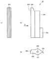
以下、本発明の実施の形態を図面に基づき詳細に説明する。まず、図1〜図2を用いて、本発明の一実施形態に係るチャイルドシート11の全体構造について説明する。なお、以下の説明における前後左右方向は、チャイルドシート11に着座した乳幼児の視線方向を基準とする。すなわち、説明中の前後方向は、図2の紙面左右方向に相当し、説明中の左右方向は、図2の紙面表裏方向に相当する。
Hereinafter, embodiments of the present invention will be described in detail with reference to the drawings. First, the overall structure of the
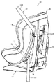
図1〜図2を参照して、本発明の一実施形態に係るチャイルドシート11は、自動車に備えられたシートベルト12を利用して自動車座席(図示せず)に締着固定され、その上に乳幼児を着座させて用いる装置であって、自動車移動中の乳幼児の安全性を確保するためのものである。
1 to 2, a
チャイルドシート11は、乳幼児が着座する座部13と、着座する乳幼児の背中を背後から支持する背もたれ部14と、背もたれ部14の背面上端部から左右に分かれて下方へと延び、背もたれ部14の下端近辺において前方へと屈曲して座部13の下端部に接続する左右一対のシェルフレーム15とを有する座席部16と、座席部16を下方から支持し、座席部16のリクライニング移動を許容するベース部17とを備える。
The
ベース部17の後端部には、シートベルト12の腰ベルト121が張り渡されるベルト張架部18が設けられている。ベルト張架部18には、張り渡された腰ベルト121の位置を保持するためのベルト係止部18aが設けられている。
At the rear end portion of the
本実施形態に係るチャイルドシート11は、背もたれ部14と左右のシェルフレーム15との交差領域に取り付けられた左右のシートベルトロック装置21を備える。このシートベルトロック装置21は、シートベルト12の肩ベルト122をその内部に保持し、肩ベルト122がチャイルドシート11を抑える押さえ位置を安定して維持するための装置である。図1〜図2に示す使用形態においては、左側に設けられたシートベルトロック装置21に、肩ベルト122が挿通されている。すなわち、チャイルドシート11は、ベルト張架部18に張架された腰ベルト121と、シートベルトロック装置21を通してシェルフレーム15に張架された肩ベルト122とによって、自動車座席に締着固定されている。
The
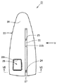
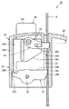
次に、図3〜図10を用いて、本発明の一実施形態に係るシートベルトロック装置21の構成について説明する。図3は、図2に示すシートベルトロック装置21、すなわちチャイルドシート11の左側に設けられたシートベルトロック装置21を示している。なお、図3、図5、および図6においては、理解の容易の観点から、シートベルトロック装置21に挿通されたシートベルト12を除外している。また、上記と同様に、説明における前後左右方向は、図2のチャイルドシート11に着座した乳幼児の視線方向を基準とする。すなわち、説明中の前後方向は図3の紙面左右方向に相当し、説明中の左右方向は図3の紙面表裏方向に相当する。
Next, the configuration of the seat
図3〜図10を参照して、本発明の一実施形態に係るシートベルトロック装置21は、シートベルトロック装置21の外形を画定する本体ケース23と、本体ケース23の内部に支持される部材であって、シートベルトロック時にシートベルト12が下方へと脱落するのを防止するためのベルト抜け止め部材24と、シートベルトロック時にシートベルト12の移動を規制するベルトロック部材25と、ベルト抜け止め部材24およびベルトロック部材25を連動して操作可能な操作部26とを備える。
3 to 10, a seat
本体ケース23は、上下方向に長尺な半楕円状の板状部材である表壁部28と、表壁部28の裏面30から右方向へ突出するように設けられた枠フレーム29とを有する。
The
表壁部28の中央部には、シートベルト12を挿通させるためのシートベルト挿通孔22が設けられている。シートベルト挿通孔22は、下端の開口端27から上方に向けて延在する凹み穴であって、上下方向に略直線上に延びている。また、表壁部28の前方下方領域には、後述する操作ボタンを外方に露出させるための貫通孔28hが設けられている。
A seat
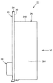
枠フレーム29は、シートベルト挿通孔22の後壁面22sを画定する後壁部291と、後壁部291の上端から前方に延在する上壁部292と、上壁部292の前端から下方に延在する前壁部293と、前壁部293の下端から後方に延在する下壁部294とから構成されている。上記したベルト抜け止め部材24、ベルトロック部材25、および操作部26は、枠フレーム29を構成する壁部291〜294によって画定される内部の空間に支持されている。
The
後壁部291と下壁部294との間には、隙間が設けられており、この隙間によって開口端27が画定されている。シートベルト12をシートベルト挿通孔22内に挿入する場合には、この開口端27から上方へ向けて滑り込ませることにより内部に挿入することが可能となっている。
A gap is provided between the
下壁部294上面の左側端部中央(図7中の紙面上方側)には、上方へ向けて突出する円形の本体ケース軸部33が設けられている。この本体ケース軸部33を介して、本体ケース23とベルト抜け止め部材24とが係合される。また、枠フレーム29の右側中央部(図7中の紙面下方側)には、上壁部292から下壁部294へ貫通するシャフト34が取り付けられている。このシャフト34は、上壁部292に設けられた貫通孔と、下壁部294に穿設された凹み穴(ともに図示せず)とに挿通され、上壁部292と下壁部294との間に亘って、シートベルト挿通孔22の延在方向に沿って延びるように配置されている。このシャフト34を介して、ベルトロック部材25が、本体ケース23に回動可能に係合される。なお、これら部材同士の係合構造の詳細については、後述する。
A circular main body
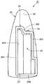
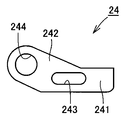
ベルト抜け止め部材24は、平坦な板状部材である。ベルト抜け止め部材24は、その後端部に位置し、シートベルトロック時に開口端27を閉鎖する抜け止め部241と、抜け止め部241の前端から斜め前方に延びる係合部242とを含む。また、抜け止め部241には、前後方向に延在する第一貫通孔243が設けられており、係合部242には、円形の第二貫通孔244がそれぞれ設けられている。ベルト抜け止め部材24は、下壁部294に設けられた上記本体ケース軸部33を第二貫通孔244に挿通させ、下壁部294上に設置される。これにより、ベルト抜け止め部材24は、本体ケース23に対して、本体ケース軸部33を中心として回動可能に係合される。
The
ベルト抜け止め部材24の上方には、操作部26が設置される。操作部26は、上記表壁部28に設けられた貫通孔28hから外方へ突出する操作ボタン261と、操作ボタン261と接続し、本体ケース23内に収容されている操作部本体262とを有する。操作部本体262は、下面後方側(図9中の紙面右側)において下方へ向けて突出するように設けられた円形の操作部軸部263と、下面前方側において下方へ突出するように設けられ、且つ左右方向に長尺に延在する足部264と、操作部本体262の右側面の前端部から右方向に突出するように設けられた板状の突出部265とを含む。なお、操作部本体262の右後端の角部には、傾斜面267が形成されている。
An
操作部26は、操作部本体262の下面に設けられた上記操作部軸部263を、ベルト抜け止め部材24に設けられた第一貫通孔243に挿通させ、ベルト抜け止め部材24上に設置される。これにより、操作部26とベルト抜け止め部材24とは、第一貫通孔243および第一貫通孔243に挿入された操作部軸部263とによって係合されることとなる。また、このときに操作部本体262の下面に設けられた足部264が、枠フレーム29の下壁部294と当接し、操作部26の姿勢を安定させる。これにより、後述するように操作部26を操作する場合において、操作部26のぐらつきを防止し、操作部26を安定して操作することができる。
The
ベルトロック部材25は、本体ケース23に設けられた上記シャフト34を介して、本体ケース23の右側領域に枢支されている。ベルトロック部材25は、上下方向に延びる円筒部251と、円筒部251の前方側に突出するように設けられ、上下方向に所定の高さを有する当接部252と、円筒部251から後方に向けて延び、その先端部に突条のクラッチ部253が複数形成されているロック部254とを有する。円筒部251は、その中心に貫通孔255を含む上下方向に長尺な円筒状部材である。当接部252は、後述するように、操作時に操作部26に設けられた上記突出部265の先端と当接する部材であって、突出部265の先端を受け入れ易い形状となるように構成されている。ロック部254は、後方に向かうにつれて高さが高くなるように形成されており、先端に設けられたクラッチ部253によって、シートベルトロック時に、シートベルト12の移動を効果的に規制することができる。ベルトロック部材25は、上記シャフト34を貫通孔255に挿通することによって、本体ケース23に回動可能に支持されている。
The
本実施形態においては、ベルトロック部材25は、本体ケース23に設けられた捩りコイルバネ(図示せず)によって、シャフト34を中心として、図7に示す方向から見て時計回り方向に常に付勢されている。この捩りコイルバネの弾性力によって、ベルトロック部材25は、シートベルト12をロックする。
In the present embodiment, the
このように、ベルトロック部材25は、シャフト34を中心とした回動により後述するシートベルトロック位置からシートベルトロック解除位置まで移動することとなる。しがって、ロック装置をよりコンパクトに構成することができる。また、シートベルトロック時において、上記クラッチ部253によってシートベルト12を噛み込んでロックすることができるため、より効果的にシートベルト12の移動を規制することができる。
In this manner, the
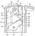
次に、図7および図11を用いて、本実施形態に係るシートベルトロック装置21の動作について説明する。図7は、シートベルトロック状態を示しており、図11は、シートベルトロック解除状態を示している。
Next, operation | movement of the
図7および図11を参照して、シートベルト12をロックしている状態においては、図7に示すように、ベルトロック部材25が、上記捩りコイルバネによって付勢され、シートベルト挿通孔22を閉鎖する位置に配置される。したがって、シートベルト挿通孔22にシートベルト12が挿入されていると、シートベルト12の前面側(紙面左側)から壁面22sに対してシートベルト12を押圧する。このとき、ロック部254の先端に設けられたクラッチ部253が、シートベルト12を噛み込む。これにより、シートベルト12の移動が規制され、シートベルト12はロックされる。
7 and 11, when the
また、図7に示すシートベルトロック状態においては、ベルト抜け止め部材24に設けられた抜け止め部241が、シートベルト挿通孔22の開口端27を閉鎖している。したがって、シートベルト12は、抜け止め部241の上方のシートベルト挿通孔22内に保持されるため、シートベルト挿通孔22の開口端27から下方へ脱落することが防止されている。
Further, in the seat belt lock state shown in FIG. 7, the retaining
シートベルトロック状態における操作部26は、図7に示すように、操作ボタン261が本体ケース23の外方に最大限突出した第一の位置に配置されている。このシートベルトロック状態からロックを解除する場合、使用者は、第一の位置にある操作ボタン261を、本体ケース23側へ向けて押し込み、操作部26を図11に示す第二の位置に配置させるよう移動させる。この移動に伴って、ベルト抜け止め部材24の第一貫通孔243と係合する操作部軸部263が、係合する第一貫通孔243の壁面を図7の紙面下方へ向けて押す。そうすると、操作部軸部263が第一貫通孔243内を相対移動するとともに、ベルト抜け止め部材24が本体ケース軸部33を中心として回動する。その結果、ベルト抜け止め部材24は、図7に示す開口端27を閉鎖する閉鎖位置から、図11に示すように開口端27を開放する開放位置へと回動により移動することとなる。
As shown in FIG. 7, the
すなわち、本実施形態に係るシートベルトロック装置21は、操作部26とベルト抜け止め部材24とを連動可能に連結する連結部を備えており、この連結部を、ベルト抜け止め部材24に設けられた第一貫通孔243および第二貫通孔244と、第一貫通孔243に挿入される操作部軸部263と、第二貫通孔244に挿入される本体ケース軸部33とによって構成している。このように、本実施形態においては、操作部26とベルト抜け止め部材24とを連動可能に連結するための連結構造を、上記のような簡単な構成によって実現している。
That is, the seat
操作部26が第一の位置から第二の位置に移動すると、それに伴って、操作部26に設けられた突出部265が、ベルトロック部材25に設けられた当接部252と当接し、これを図7の紙面下方へ向けて押す。そうすると、ベルトロック部材25は、シャフト34を中心として、図7に示す方向から見て反時計回りに、上記捩りコイルバネの弾性力に逆らって回動する。そして、操作部本体262の右後端角部に形成されている傾斜面267と、ロック部254の側面256とが当接し、操作部26、ベルトロック部材25、およびベルト抜け止め部材24の動きが規制される。こうして、ベルトロック部材25は、図7に示すベルトロック位置から、図11に示すようにシートベルト挿通孔22を開放するベルトロック解除位置まで回動により移動する。この状態となると、ベルトロック部材25によるシートベルト12に対する押圧が解除され、シートベルト12がシートベルト挿通孔22内を移動可能となる。
When the
このように、使用者は、操作ボタン261を押し込むことによって、ベルト抜け止め部材24およびベルトロック部材25を、ロック解除の位置に連動して移動させることができる。その結果、シートベルトロック装置21は、シートベルト12をシートベルト挿通孔22に出し入れ可能なロック解除状態となる。
In this way, the user can move the
図11に示すロック解除状態から、使用者が操作部26を離すと、上記捩りコイルバネの弾性力によって、ベルトロック部材25が、図11に示す方向から見て時計回りに回動し、図7に示すベルトロック位置へと復帰する。そして、ベルトロック部材25が、再びシートベルト12を壁面22sに対して押圧し、クラッチ部253がシートベルト12を噛み込んでロックする。
When the user releases the
ベルトロック部材25がベルトロック解除位置からベルトロック位置に回動するのに伴って、当接部252が突出部265を図11の紙面上方へ向けて押す。そうすると、操作部26が第二の位置から第一の位置へと押し戻される。これとともに、ベルト抜け止め部材24が、図11に示す開放位置から、図7に示す閉鎖位置へと復帰して、シートベルト挿通孔22の開口端27を閉鎖する。こうして、シートベルトロック装置21は、ロック状態となる。
As the
本実施形態に係るシートベルトロック装置21は、上記構成を備えることから、チャイルドシート11を自動車座席に締着固定する際に、シートベルト12をロックした状態でシートベルト12を引っ張る作業を行った場合や、チャイルドシート11に衝突等による衝撃が加えられた場合において、シートベルト12をシートベルト挿通孔22内に確実に保持することができる。これについて、以下に説明する。
Since the
シートベルトロック状態でシートベルト12を引っ張った場合や、チャイルドシート11に衝撃が加わった場合、シートベルト12から、当該シートベルトを噛み込むベルトロック部材25に対して、相対的な力が伝達されることとなる。その結果、ベルトロック部材25をベルトロック解除位置に移動させてしまうことも起こり得る。この場合、ベルトロック部材25は、ベルトロック位置からベルトロック解除位置まで、シャフト34を中心として回動する。
When the
このようにベルトロック部材25が単体として回動すると、操作部26の突出部265と、ベルトロック部材25の当接部252との間の当接が解除される。すなわち、ベルトロック部材25が、外部からの力によって単体として回動した場合、ベルトロック部材25と操作部26との間の機械的結合が解除される構成となっている。このため、操作部26は、ベルトロック部材25の単体としての回動によって、何ら影響を受けることがない。したがって、上記のようにベルトロック部材25単体が回動した場合においても、操作部26の位置は確実に維持される。すなわち、ベルト抜け止め部材24の位置も確実に維持されることとなる。これにより、開口端27の閉鎖状態が維持されるため、シートベルト12がシートベルト挿通孔22から脱落することを防止することができる。
When the
このように、本実施形態に係るシートベルトロック装置21によれば、チャイルドシート11を自動車座席に締着固定する際にシートベルト12を引っ張る作業を行った場合に、仮にベルトロック部材25がベルトロック解除位置へ向けて移動させられたとしても、シートベルト12をシートベルト挿通孔22内に確実に保持することができる。これにより、チャイルドシートの取り付け作業時にシートベルト12がシートベルトロック装置21から脱落することを防止することができるため、取り付け作業に係る利便性を向上させることができる。
As described above, according to the seat
また、衝突等によりチャイルドシート11に衝撃が加えられた場合においても、シートベルトロック装置21は、上記のようにシートベルト12をシートベルト挿通孔22内に確実に保持することができるため、チャイルドシート11を抑えるシートベルト12の押さえ位置をより安定させることができる。したがって、チャイルドシート11を自動車座席にシートベルト12を介してより安定して締着固定することができる。
Further, even when an impact is applied to the
また、本実施形態によれば、使用者は、一つの操作ボタン261を押し込む操作をするだけで、シートベルト12の出し入れと、シートベルト12のロック/ロック解除といった作業を行うことができる。したがって、チャイルドシート11を自動車座席により容易に設置することが可能となる。
Further, according to the present embodiment, the user can perform operations such as putting in and out of the
なお、本実施形態においては、ベルトロック部材が本体ケースに枢支され、ベルトロック位置とベルトロック解除位置との間を回動により移動する場合について述べたが、これに限らず、ベルトロック部材が、ベルトロック位置とベルトロック解除位置との間を摺動するように本体ケースに支持される構成であってもよい。 In the present embodiment, the case where the belt lock member is pivotally supported by the main body case and moves between the belt lock position and the belt lock release position by rotation is described. However, it may be configured to be supported by the main body case so as to slide between the belt lock position and the belt lock release position.
また、本実施形態においては、操作部とベルトロック部材との機械的な結合を、操作部に設けられた突出部とベルトロック部材に設けられた当接部との当接により実現していたが、これに限らず、操作部を第一の位置から第二の位置へ操作した場合にはベルトロック部材に力を伝達し、且つベルトロック部材単体がベルトロック位置からベルトロック解除位置へ移動する場合には操作部へは力が伝達されない構成であれば、如何なるものであってもよい。例えば、操作部とベルトロック部材との連結を、一方方向への力のみを伝達可能なワンウェイクラッチによって構成することも可能である。 In the present embodiment, the mechanical connection between the operation portion and the belt lock member is realized by the contact between the protruding portion provided on the operation portion and the contact portion provided on the belt lock member. However, not limited to this, when the operation unit is operated from the first position to the second position, force is transmitted to the belt lock member, and the belt lock member alone moves from the belt lock position to the belt lock release position. In this case, any configuration may be used as long as no force is transmitted to the operation unit. For example, the connection between the operation unit and the belt lock member can be configured by a one-way clutch capable of transmitting only a force in one direction.
また、本実施形態においては、操作部とベルト抜け止め部材とを連動可能に連結する連結部を、第一貫通孔および第二貫通孔と、これと係合する本体ケース軸部および操作部軸部とによって構成した場合について述べたが、これに限らず、操作部とベルト抜け止め部材とを、上記したように連動して動作することができる構成であれば、如何なる連結構造であってもよい。 Moreover, in this embodiment, the connection part which connects an operation part and a belt retaining member so that interlocking is possible, a main body case axial part and operation part axis | shaft which engage with this with a 1st through-hole and a 2nd through-hole However, the present invention is not limited to this, and any connection structure can be used as long as the operation unit and the belt retaining member can be operated in conjunction with each other as described above. Good.
また、本実施形態においては、ベルトロック部材をベルトロック位置に向けて付勢する付勢手段を、コスト性に優れた捩りコイルバネによって構成した場合について述べたが、これに限らず、ゴム材料や磁石等、ベルトロック部材をベルトロック位置に向けて付勢可能であれば、如何なる部材を用いてもよい。 Further, in the present embodiment, the case where the biasing means for biasing the belt lock member toward the belt lock position is configured by a torsion coil spring excellent in cost is described. Any member such as a magnet may be used as long as the belt lock member can be biased toward the belt lock position.
以上、図面を参照して本発明の実施の形態を説明したが、本発明は、図示した実施の形態のものに限定されない。図示した実施の形態に対して、本発明と同一の範囲内において、あるいは均等の範囲内において、種々の修正や変形を加えることが可能である。 As mentioned above, although embodiment of this invention was described with reference to drawings, this invention is not limited to the thing of embodiment shown in figure. Various modifications and variations can be made to the illustrated embodiment within the same range as the present invention or within an equivalent range.
本発明は、取り付けの利便性および安定性に優れたシートベルトロック装置を備えるチャイルドシートを提供するものであって、チャイルドシート製造業に有利に利用される。 The present invention provides a child seat provided with a seat belt locking device excellent in convenience and stability of attachment, and is advantageously used in the child seat manufacturing industry.
11 チャイルドシート、12 シートベルト、121 腰ベルト、122 肩ベルト、13 座部、14 背もたれ部、15 シェルフレーム、16 座席部、17 ベース部、18 ベルト張架部、18a ベルト係止部、21 シートベルトロック装置、22 シートベルト挿通孔、23 本体ケース、24 ベルト抜け止め部材、241 抜け止め部、242 係合部、25 ベルトロック部材、251 円筒部、252 当接部、253 クラッチ部、254 ロック部、26 操作部、261 操作ボタン、262 操作部本体、264 足部、265 突出部、27 開口端、28 表壁部、29 枠フレーム、291,292,293,294 壁部、22s,30,256,267 面、28h,243,244,255 貫通孔、33,263 軸部、34 シャフト。
DESCRIPTION OF
Claims (6)
開口端から一方に向けて延在し、前記シートベルトを前記開口端から内部に受け入れ可能なシートベルト挿通孔を有する本体ケースと、
前記シートベルト挿通孔の内部に挿入された前記シートベルトが外方へと脱落するのを防止するために前記開口端を閉鎖する閉鎖位置と、前記シートベルトが前記シートベルト挿通孔に出入り可能な状態とするために前記開口端を開放する開放位置との間を移動可能となるように前記本体ケースに支持されるベルト抜け止め部材と、
前記シートベルト挿通孔に挿入された前記シートベルトの一方面側から前記シートベルトを押圧し、前記シートベルト挿通孔を画定する壁面に前記シートベルトを押し当てて前記シートベルトの移動を規制するベルトロック位置と、前記シートベルトに対する押圧を解除して前記シートベルトの移動を許容するベルトロック解除位置との間を移動可能となるように前記本体ケースに支持されるベルトロック部材と、
前記ベルトロック部材を前記ベルトロック位置に向けて付勢する付勢手段と、
第一の位置と第二の位置との間を移動可能となるように前記本体ケースに支持され、前記第一の位置から前記第二の位置に移動するように操作されたときに、前記ベルトロック部材と当接し、前記ベルトロック部材を前記ベルトロック解除位置に向けて押す操作部と、
前記操作部が前記第一の位置にあるときには、前記ベルト抜け止め部材を前記閉鎖位置に配置させ、前記操作部が前記第二の位置にあるときには、前記ベルト抜け止め部材を前記開放位置に配置させるように、前記操作部と前記ベルト抜け止め部材とを連動可能に連結する連結部と、を備える、シートベルトロック装置。 A seat belt locking device provided on a child seat that is stretched over and fixed to a seat of an automobile.
A main body case having a seat belt insertion hole extending from the opening end toward one side and receiving the seat belt from the opening end to the inside;
A closed position for closing the opening end to prevent the seat belt inserted into the seat belt insertion hole from dropping off; and the seat belt can enter and exit the seat belt insertion hole. A belt retaining member supported by the main body case so as to be movable between an open position for opening the open end in order to be in a state;
A belt that presses the seat belt from one side of the seat belt inserted into the seat belt insertion hole and presses the seat belt against a wall surface that defines the seat belt insertion hole to restrict movement of the seat belt. A belt lock member supported by the body case so as to be movable between a lock position and a belt lock release position that releases the pressure on the seat belt and allows the seat belt to move;
Biasing means for biasing the belt lock member toward the belt lock position;
The belt is supported by the main body case so as to be movable between a first position and a second position, and is operated to move from the first position to the second position. An operation unit that contacts the lock member and pushes the belt lock member toward the belt lock release position;
When the operating portion is in the first position, the belt retaining member is disposed in the closed position, and when the operating portion is in the second position, the belt retaining member is disposed in the open position. A seat belt locking device comprising: a connecting portion that connects the operation portion and the belt retaining member so as to be interlocked with each other.
軸を介して前記本体ケースに回動可能に支持され、
その一方側端部がベルトロック時に前記シートベルトを噛み込む突条のクラッチ部を構成し、
その他方端部が前記操作部と当接する当接部を構成する、請求項1に記載のシートベルトロック装置。 The belt lock member is
It is rotatably supported by the body case via a shaft,
The one side end portion constitutes a clutch portion of a ridge that bites the seat belt when the belt is locked,
The seat belt lock device according to claim 1, wherein the other end portion constitutes a contact portion that contacts the operation portion.
前記ベルト抜け止め部材に設けられた第一貫通孔および第二貫通孔と、
前記操作部に設けられ、前記第一貫通孔に挿入される操作部軸部と、
前記本体ケースに設けられ、前記第二貫通孔に挿入される本体ケース軸部と、から構成される、請求項1または2に記載のシートベルトロック装置。 The connecting portion is
A first through hole and a second through hole provided in the belt retaining member;
An operating portion shaft provided in the operating portion and inserted into the first through hole;
The seat belt lock device according to claim 1 or 2, comprising a main body case shaft portion provided in the main body case and inserted into the second through hole.
当該操作ボタンが前記本体ケース側に向けて押し込まれると、前記操作部が前記第一の位置から前記第二の位置へと移動する、請求項1〜3のいずれかに記載のシートベルトロック装置。 The operation unit has an operation button arranged to protrude outward from the main body case,
The seat belt lock device according to any one of claims 1 to 3, wherein when the operation button is pushed toward the main body case side, the operation unit moves from the first position to the second position. .
乳幼児が着座する座部と、
着座する乳幼児の背中を背後から支持する背もたれ部と、
前記背もたれ部の背面側上方部に設けられ、請求項1〜5のいずれかに記載の特徴を有するシートベルトロック装置と、を備えるチャイルドシート。
A child seat in which a seat belt of an automobile is stretched and fixed to a seat of the automobile,
A seat where an infant sits;
A backrest that supports the back of the sitting infant from behind,
A child seat comprising: a seat belt locking device provided at an upper portion on the back side of the backrest portion and having the characteristics according to any one of claims 1 to 5.
Priority Applications (5)
| Application Number | Priority Date | Filing Date | Title |
|---|---|---|---|
| JP2011004746A JP5680975B2 (en) | 2011-01-13 | 2011-01-13 | Child seat belt lock device and child seat |
| KR1020110104451A KR20120082325A (en) | 2011-01-13 | 2011-10-13 | Lock apparatus of seat belt for child seat and child seat |
| EP12150607A EP2476582A1 (en) | 2011-01-13 | 2012-01-10 | Seat belt lock device of a child car seat, and a child car seat |
| TW101101192A TW201228864A (en) | 2011-01-13 | 2012-01-12 | Seatbelt lock device for child seat and child seat |
| CN2012100658159A CN102602359A (en) | 2011-01-13 | 2012-01-13 | Seat belt lock device of a child car seat, and a child car seat |
Applications Claiming Priority (1)
| Application Number | Priority Date | Filing Date | Title |
|---|---|---|---|
| JP2011004746A JP5680975B2 (en) | 2011-01-13 | 2011-01-13 | Child seat belt lock device and child seat |
Publications (2)
| Publication Number | Publication Date |
|---|---|
| JP2012144174A true JP2012144174A (en) | 2012-08-02 |
| JP5680975B2 JP5680975B2 (en) | 2015-03-04 |
Family
ID=45491397
Family Applications (1)
| Application Number | Title | Priority Date | Filing Date |
|---|---|---|---|
| JP2011004746A Active JP5680975B2 (en) | 2011-01-13 | 2011-01-13 | Child seat belt lock device and child seat |
Country Status (5)
| Country | Link |
|---|---|
| EP (1) | EP2476582A1 (en) |
| JP (1) | JP5680975B2 (en) |
| KR (1) | KR20120082325A (en) |
| CN (1) | CN102602359A (en) |
| TW (1) | TW201228864A (en) |
Cited By (6)
| Publication number | Priority date | Publication date | Assignee | Title |
|---|---|---|---|---|
| JP2015189298A (en) * | 2014-03-27 | 2015-11-02 | コンビ株式会社 | child seat |
| JP2015189296A (en) * | 2014-03-27 | 2015-11-02 | コンビ株式会社 | child seat |
| CN108430274A (en) * | 2015-12-21 | 2018-08-21 | 阿特萨纳公司 | The padded seat of children |
| KR20220001766A (en) * | 2020-06-30 | 2022-01-06 | 주식회사다스 | Damping device for swivel seat |
| KR20220069495A (en) * | 2020-11-20 | 2022-05-27 | 주식회사다스 | Damping device for swivel seat |
| JP2025514777A (en) * | 2022-04-21 | 2025-05-09 | ワンダーランド スイツァーランド アーゲー | child seat |
Families Citing this family (11)
| Publication number | Priority date | Publication date | Assignee | Title |
|---|---|---|---|---|
| FR2995840B1 (en) * | 2012-09-27 | 2014-10-10 | Sas Bb Design | CAR SEAT FOR CHILDREN |
| KR101523833B1 (en) * | 2013-01-14 | 2015-06-01 | 이지영 | Belt lock device of the infant car seat |
| CN103622214A (en) * | 2013-10-29 | 2014-03-12 | 张振兴 | Automobile safety belt male buckle |
| CN103622215A (en) * | 2013-10-29 | 2014-03-12 | 方樱儒 | Automobile safety belt female buckle |
| CN107826001B (en) * | 2016-09-16 | 2020-05-22 | 明门瑞士股份有限公司 | Supporting leg and child safety seat assembly thereof |
| DE102018120870B4 (en) * | 2017-08-28 | 2021-06-10 | Wonderland Switzerland Ag | Child safety seat |
| US11155187B2 (en) * | 2018-09-12 | 2021-10-26 | Wonderland Switzerland Ag | Child restraint base and child restraint system |
| CN109910697B (en) * | 2018-12-29 | 2021-08-27 | 深圳市南山区月亮湾小学 | Portable child safety seat used on automobile |
| CN110843619A (en) * | 2019-12-10 | 2020-02-28 | 东莞贯新幼童用品有限公司 | Safety seat |
| CN112606794B (en) * | 2021-01-14 | 2025-03-07 | 宁波宝贝第一母婴用品有限公司 | A child safety seat belt tensioning device |
| CN115303143A (en) * | 2021-05-07 | 2022-11-08 | 哥瑞考儿童产品公司 | Child-care related appliance |
Citations (2)
| Publication number | Priority date | Publication date | Assignee | Title |
|---|---|---|---|---|
| JP2002120617A (en) * | 2000-10-16 | 2002-04-23 | Combi Corp | child seat |
| JP2008296691A (en) * | 2007-05-30 | 2008-12-11 | Takata Corp | Seat belt clamp device for child seat and child seat |
Family Cites Families (5)
| Publication number | Priority date | Publication date | Assignee | Title |
|---|---|---|---|---|
| JP2001347860A (en) | 2000-06-07 | 2001-12-18 | Riiman Kk | Seat belt fixing device for child seat |
| CN2642600Y (en) * | 2003-07-24 | 2004-09-22 | 赵纯立 | A safety belt buckle device for a child-specific car seat |
| NL1029417C2 (en) * | 2005-07-04 | 2007-01-08 | Maxi Miliaan Bv | Children's vehicle seat. |
| CN201065082Y (en) * | 2006-11-14 | 2008-05-28 | 长春旭阳汽车技术开发有限公司 | Children chair of automobile |
| JP5326294B2 (en) * | 2008-02-15 | 2013-10-30 | タカタ株式会社 | child seat |
-
2011
- 2011-01-13 JP JP2011004746A patent/JP5680975B2/en active Active
- 2011-10-13 KR KR1020110104451A patent/KR20120082325A/en not_active Withdrawn
-
2012
- 2012-01-10 EP EP12150607A patent/EP2476582A1/en not_active Withdrawn
- 2012-01-12 TW TW101101192A patent/TW201228864A/en unknown
- 2012-01-13 CN CN2012100658159A patent/CN102602359A/en active Pending
Patent Citations (2)
| Publication number | Priority date | Publication date | Assignee | Title |
|---|---|---|---|---|
| JP2002120617A (en) * | 2000-10-16 | 2002-04-23 | Combi Corp | child seat |
| JP2008296691A (en) * | 2007-05-30 | 2008-12-11 | Takata Corp | Seat belt clamp device for child seat and child seat |
Cited By (8)
| Publication number | Priority date | Publication date | Assignee | Title |
|---|---|---|---|---|
| JP2015189298A (en) * | 2014-03-27 | 2015-11-02 | コンビ株式会社 | child seat |
| JP2015189296A (en) * | 2014-03-27 | 2015-11-02 | コンビ株式会社 | child seat |
| CN108430274A (en) * | 2015-12-21 | 2018-08-21 | 阿特萨纳公司 | The padded seat of children |
| KR20220001766A (en) * | 2020-06-30 | 2022-01-06 | 주식회사다스 | Damping device for swivel seat |
| KR102360599B1 (en) | 2020-06-30 | 2022-02-09 | 주식회사 다스 | Damping device for swivel seat |
| KR20220069495A (en) * | 2020-11-20 | 2022-05-27 | 주식회사다스 | Damping device for swivel seat |
| KR102453066B1 (en) | 2020-11-20 | 2022-10-11 | 주식회사 다스 | Damping device for swivel seat |
| JP2025514777A (en) * | 2022-04-21 | 2025-05-09 | ワンダーランド スイツァーランド アーゲー | child seat |
Also Published As
| Publication number | Publication date |
|---|---|
| JP5680975B2 (en) | 2015-03-04 |
| KR20120082325A (en) | 2012-07-23 |
| EP2476582A1 (en) | 2012-07-18 |
| TW201228864A (en) | 2012-07-16 |
| CN102602359A (en) | 2012-07-25 |
Similar Documents
| Publication | Publication Date | Title |
|---|---|---|
| JP5680975B2 (en) | Child seat belt lock device and child seat | |
| CN102442238B (en) | Child seat | |
| US9162590B2 (en) | Seat slide apparatus for vehicle | |
| JP6308665B2 (en) | Seat belt device for vehicle seat | |
| US20140210245A1 (en) | Unlocking mechanism for inclinable headrest | |
| JP2018020673A (en) | Vehicle seat | |
| CN106183920A (en) | The headrest of automotive seat and include the seat of this headrest | |
| JP2007055433A (en) | Child seat | |
| US20110084534A1 (en) | Headrest folding structure for a vehicle | |
| JP6405205B2 (en) | Seat device | |
| JP4471340B2 (en) | Buckle device | |
| JP5586359B2 (en) | Child seat belt fixing device and car child seat having the same | |
| JP4101982B2 (en) | Buckle device | |
| JP5710831B1 (en) | Headrest tilting device and headrest | |
| JP2011079414A (en) | Structure for assembling unlock operation member of seat for vehicle and lock/unlock device of seat for vehicle | |
| JP5365357B2 (en) | Operation lever device for vehicle seat | |
| JP5952722B2 (en) | Vehicle seat | |
| JP5580088B2 (en) | Side-up seat locking mechanism | |
| JP6917316B2 (en) | Reclining equipment and vehicle seats | |
| TWI896078B (en) | Child safety seat | |
| CN223014414U (en) | Children's Carrier | |
| JPH051579U (en) | Child seat | |
| JP3991678B2 (en) | Remote control unit storage device for vehicle seat | |
| JP2011000908A (en) | Buckle structure of vehicular seat | |
| JP2025028639A (en) | Buckles and seat belt devices |
Legal Events
| Date | Code | Title | Description |
|---|---|---|---|
| RD03 | Notification of appointment of power of attorney |
Free format text: JAPANESE INTERMEDIATE CODE: A7423 Effective date: 20130125 |
|
| A621 | Written request for application examination |
Free format text: JAPANESE INTERMEDIATE CODE: A621 Effective date: 20131213 |
|
| A977 | Report on retrieval |
Free format text: JAPANESE INTERMEDIATE CODE: A971007 Effective date: 20141010 |
|
| A131 | Notification of reasons for refusal |
Free format text: JAPANESE INTERMEDIATE CODE: A131 Effective date: 20141021 |
|
| A521 | Request for written amendment filed |
Free format text: JAPANESE INTERMEDIATE CODE: A523 Effective date: 20141203 |
|
| TRDD | Decision of grant or rejection written | ||
| A01 | Written decision to grant a patent or to grant a registration (utility model) |
Free format text: JAPANESE INTERMEDIATE CODE: A01 Effective date: 20141224 |
|
| A61 | First payment of annual fees (during grant procedure) |
Free format text: JAPANESE INTERMEDIATE CODE: A61 Effective date: 20150108 |
|
| R150 | Certificate of patent or registration of utility model |
Ref document number: 5680975 Country of ref document: JP Free format text: JAPANESE INTERMEDIATE CODE: R150 |
|
| R250 | Receipt of annual fees |
Free format text: JAPANESE INTERMEDIATE CODE: R250 |
|
| R250 | Receipt of annual fees |
Free format text: JAPANESE INTERMEDIATE CODE: R250 |
|
| R250 | Receipt of annual fees |
Free format text: JAPANESE INTERMEDIATE CODE: R250 |
|
| S531 | Written request for registration of change of domicile |
Free format text: JAPANESE INTERMEDIATE CODE: R313531 |
|
| S533 | Written request for registration of change of name |
Free format text: JAPANESE INTERMEDIATE CODE: R313533 |
|
| R350 | Written notification of registration of transfer |
Free format text: JAPANESE INTERMEDIATE CODE: R350 |
|
| R250 | Receipt of annual fees |
Free format text: JAPANESE INTERMEDIATE CODE: R250 |
|
| R250 | Receipt of annual fees |
Free format text: JAPANESE INTERMEDIATE CODE: R250 |
|
| R250 | Receipt of annual fees |
Free format text: JAPANESE INTERMEDIATE CODE: R250 |
|
| R250 | Receipt of annual fees |
Free format text: JAPANESE INTERMEDIATE CODE: R250 |
|
| R250 | Receipt of annual fees |
Free format text: JAPANESE INTERMEDIATE CODE: R250 |
|
| R250 | Receipt of annual fees |
Free format text: JAPANESE INTERMEDIATE CODE: R250 |