JP2012144193A - Airbag device for passenger seat - Google Patents
Airbag device for passenger seat Download PDFInfo
- Publication number
- JP2012144193A JP2012144193A JP2011005234A JP2011005234A JP2012144193A JP 2012144193 A JP2012144193 A JP 2012144193A JP 2011005234 A JP2011005234 A JP 2011005234A JP 2011005234 A JP2011005234 A JP 2011005234A JP 2012144193 A JP2012144193 A JP 2012144193A
- Authority
- JP
- Japan
- Prior art keywords
- engaged
- instrument panel
- piece
- case body
- hook piece
- Prior art date
- Legal status (The legal status is an assumption and is not a legal conclusion. Google has not performed a legal analysis and makes no representation as to the accuracy of the status listed.)
- Pending
Links
- 238000007667 floating Methods 0.000 claims abstract description 15
- 239000002184 metal Substances 0.000 claims description 13
- 238000005452 bending Methods 0.000 claims description 5
- 239000003351 stiffener Substances 0.000 abstract description 14
- 238000013461 design Methods 0.000 description 10
- 238000002474 experimental method Methods 0.000 description 8
- 239000013585 weight reducing agent Substances 0.000 description 7
- 238000012986 modification Methods 0.000 description 5
- 230000004048 modification Effects 0.000 description 5
- 238000005516 engineering process Methods 0.000 description 3
- 238000003466 welding Methods 0.000 description 2
- 238000007796 conventional method Methods 0.000 description 1
- 238000011161 development Methods 0.000 description 1
- 238000005304 joining Methods 0.000 description 1
- 238000004519 manufacturing process Methods 0.000 description 1
- 238000000034 method Methods 0.000 description 1
- 230000002093 peripheral effect Effects 0.000 description 1
- 229920005989 resin Polymers 0.000 description 1
- 239000011347 resin Substances 0.000 description 1
- 229920003002 synthetic resin Polymers 0.000 description 1
- 239000000057 synthetic resin Substances 0.000 description 1
Images


Landscapes
- Air Bags (AREA)
Abstract
Description
この発明は、自動車のインストルメントパネルにおける助手席に対向する部位に設置される助手席用エアバッグ装置に関する。 The present invention relates to an airbag device for a passenger seat that is installed in a portion of a vehicle instrument panel that faces the passenger seat.
この種の従来の助手席用エアバッグ装置として、例えば、特許文献1に記載の技術が知られている。かかる従来の技術は、同特許文献1に使用されている符号を付して説明すると、エアバッグを内蔵するエアバッグモジュール1をインストルメントパネル2内に装着する場合に、エアバッグモジュール1が、エアバッグを受容し且つエアバッグ展開時の放出口を上端面に有するケーシング3と、その放出口を覆うようにケーシング3の上部に一体化されたリッド4とを有し、ケーシング3の下面に設けられたブラケット部5を車両側のボディパネルのスティフナ6にネジ止めなどにて固設されている。
As this type of conventional airbag device for a passenger seat, for example, a technique described in
従って、上記従来の技術においては、エアバッグモジュール1は、ケーシングの下面に設けられたブラケット部5を車両側のボディパネルのスティフナ6にネジ止めすることによって、インストルメントパネル2に固定的に設置されていることになる。
Therefore, in the above prior art, the
しかしながら、エアバッグモジュール1は、インストルメントパネル2の上部側裏面に配設されていることから、何かの物体が突き当たったような場合その衝撃を緩和すべく、インストルメントパネル2に対して下方向に逃げるように構成されていることが望ましいのであるが、上記従来の技術においては、インストルメントパネル2に固定的に設置されていることから、下方向に逃げるような構成とする場合には、ブラケット部5とスティフナ6との関係を如何に設計するかは非常に難しく、度重なる実験や試作を繰り返すことによって実証的に行う必要があって、多大な設計開発工数を必要としていた。
However, since the
また、上記従来の技術における助手席用エアバッグ装置は、エアバッグモジュール1をブラケット部5及びスティフナ6を用いてインストルメントパネル2に設置するという構成をとっていることから、ブラケット部5及びスティフナ6の重量分高重量化してしまい、現在大きく求められている車両軽量化の面に悖ることになる。
Further, since the airbag device for the passenger seat in the above-described conventional technology is configured to install the
そこで、この発明は、上記従来の技術における課題に鑑み、従来のブラケット部やスティフナ等を用いずに車両の軽量化を果たすと共に、物体が当接したような場合にインストルメントパネルに対してフローティング構成にした助手席用エアバッグ装置を提供することを目的としている。 Accordingly, in view of the above-described problems in the conventional technology, the present invention achieves weight reduction of the vehicle without using a conventional bracket portion, stiffener, or the like, and floats with respect to the instrument panel when an object comes into contact. An object of the present invention is to provide an airbag device for a passenger seat configured as described above.
この発明に係る助手席用エアバッグ装置は、自動車のインストルメントパネルの固定部位に折り畳まれたエアバッグが収容されたケース体を設置することによりインストルメントパネルに組み付け構成する助手席用エアバッグ装置であって、ケース体及びインストルメントパネルの固定部位のうち、一方にフック片を複数個形成すると共に、他方にフック片が係合する被係合体を複数個設けておき、該被係合体にフック片をインストルメントパネルの固定部に対して下方に可動可能に係合することにより、ケース体をインストルメントパネルに対してフローティング状態で設置するように構成したことを特徴とする。 An airbag device for a passenger seat according to the present invention is an airbag device for a passenger seat that is assembled to an instrument panel by installing a case body in which a folded airbag is accommodated in a fixed portion of an instrument panel of an automobile. In the fixed portion of the case body and the instrument panel, a plurality of hook pieces are formed on one side, and a plurality of engaged bodies to be engaged with the hook pieces are provided on the other side. The case body is configured to be installed in a floating state with respect to the instrument panel by engaging the hook piece movably downward with respect to the fixed portion of the instrument panel.
かかる構成を有するこの発明は、エアバッグが収容されたケース体を、フック片と被係合体との係合によって、インストルメントパネルの固定部位に設置するように構成しているために、従来のブラケットやスティフナを用いず、車両の軽量化を果たすことができ、しかも、フック片と被係合体とを可動可能に係合することにより、ケース体をインストルメントパネルに対してフローティング構成とすることができることから、何らかの物体が当接した場合にはケース体がインストルメントパネルに対して下方向に逃げる構成が、多大な設計工数や実験工数を費やすことなく簡単に実現されることができる。 In the present invention having such a configuration, the case body in which the airbag is accommodated is configured to be installed at the fixed portion of the instrument panel by the engagement between the hook piece and the engaged body. The weight of the vehicle can be reduced without using brackets or stiffeners, and the case body is made floating with respect to the instrument panel by movably engaging the hook piece and the engaged body. Therefore, the configuration in which the case body escapes downward with respect to the instrument panel when any object comes into contact can be easily realized without spending a great amount of design man-hours and experiment man-hours.
また、この発明に係る助手席用エアバッグ装置は、上記発明の実施の形態として、被係合体が金属製のU字状ピンにて構成して、U字状ピンの一方の脚片部にフック片を係合するように構成している。 Further, in the passenger seat airbag device according to the present invention, as an embodiment of the above-described invention, the engaged body is constituted by a metal U-shaped pin, and is formed on one leg piece of the U-shaped pin. The hook piece is configured to be engaged.
かかる構成を有するこの発明は、被係合体を金属製のU字状ピンにて構成したことから、車両の軽量化に資すると共に、U字状ピンの一方の脚片部に対してフック片が係合状態を保持したままで可動可能に構成することができ、この結果、ケース体をインストルメントパネルに対するフローティング構成を、多大な設計工数や実験工数を費やすことなく簡単に実現されることができる。 In the present invention having such a configuration, since the engaged body is made of a metal U-shaped pin, it contributes to weight reduction of the vehicle, and a hook piece is provided to one leg piece portion of the U-shaped pin. It can be configured to be movable while maintaining the engaged state, and as a result, the floating configuration of the case body with respect to the instrument panel can be easily realized without spending a great deal of design man-hours and experiment man-hours. .
また、この発明に係る助手席用エアバッグ装置は、上記発明の実施の形態として、U字状ピンの外周に被係合片を装着し、被係合片が、フック片をU字状ピンに対して係合解除動作方向に移動させる係合解除傾斜面部と、係合解除傾斜面をフック片が乗り越えた後フック片の弾性復帰力により係合方向に移動することにより係合する被係合傾斜面部とを有して構成している。 Further, in the passenger seat airbag device according to the present invention, as an embodiment of the above invention, an engaged piece is mounted on the outer periphery of a U-shaped pin, and the engaged piece is a hook-shaped pin. A disengagement inclined surface portion that moves in the disengagement operation direction with respect to the engagement disengagement inclined surface, and a hook piece that moves over the disengagement inclination surface by moving in the engagement direction by the elastic return force of the hook piece And a sloped surface portion.
かかる構成を有するこの発明は、被係合片が、フック片をU字状ピンに対して係合解除動作方向に移動させる係合解除傾斜面部と、係合解除傾斜面部をフック片が乗り越えた後フック片の弾性復帰力により係合方向に移動することにより係合する被係合傾斜面部とを有していることから、フック片の被係合片に対する係合を容易にすることができる。 In the present invention having such a configuration, the engaged piece includes an engagement release inclined surface portion that moves the hook piece in the engagement release operation direction with respect to the U-shaped pin, and the hook piece gets over the engagement release inclined surface portion. Since it has the to-be-engaged inclined surface part engaged by moving to an engagement direction with the elastic return force of a rear hook piece, engagement with the to-be-engaged piece of a hook piece can be made easy. .
また、この発明に係る助手席用エアバッグ装置は、上記発明の実施の形態として、被係合体が、金属製の針金の折曲により形成したループ状の枠体部をL字状に折曲することにより互いに対向する一対の折曲部を形成し、両折曲部に係合部を橋渡し形成し、且つ、枠体部の互いに対向する側端辺部の一方を、ケース及びインストルメントパネルの固定部位のうち、一方に形成した枢支部に揺動可能に枢着すると共に、枠体部の互いに対向する側端辺部の他方を、ケース及びインストルメントパネルの固定部位のうち他方に形成したフック片に係合するように形成して構成している。 Further, in the passenger seat airbag device according to the present invention, as an embodiment of the above invention, the engaged body bends a loop-shaped frame portion formed by bending a metal wire into an L shape. To form a pair of bent portions opposed to each other, to form an engaging portion between both bent portions, and to form one of the side end sides facing each other of the frame body portion as a case and an instrument panel The other fixed side part of the frame body part is formed on the other of the fixed parts of the case and the instrument panel. It is formed and configured to engage with the hook piece.
かかる構成を有するこの発明は、被係合体を金属製の針金を折曲することによって形成していることから、車両の軽量化に資すると共に、被係合体を構成する枠体部の他方の側端辺部を被係合体に係合する場合に他方の側端辺部が被係合体に対する係合状態を可動可能に構成することにより、ケース体をインストルメントパネルに対するフローティング状態に設置する構成を、多大な設計工数や実験工数を費やすことなく簡単に実現されることができる。 In the present invention having such a configuration, since the engaged body is formed by bending a metal wire, it contributes to the weight reduction of the vehicle and the other side of the frame body portion constituting the engaged body. A configuration in which the case body is placed in a floating state with respect to the instrument panel by configuring the other side end side portion to be movable with respect to the engaged body when the end side portion is engaged with the engaged body. It can be easily realized without spending a great amount of design and experiment.
また、この発明に係る助手席用エアバッグ装置は、上記発明の実施の形態として、ケース体とインストルメントパネルの固定部位との間に、スプリングを介在させて、スプリングの付勢力により被係合体に対するフック片の係合関係を助成するように構成している。 Further, in the passenger seat airbag apparatus according to the present invention, as an embodiment of the above invention, a spring is interposed between the case body and the fixed part of the instrument panel, and the engaged body is energized by the urging force of the spring. It is comprised so that the engagement relationship of the hook piece may be supported.
かかる構成を有するこの発明は、被係合体に対するフック片の係合関係をスプリングの付勢力により保持していることから、インストルメントパネルに対してケース体が不用意に取り外されることがない。 In the present invention having such a configuration, the case body is not inadvertently detached from the instrument panel because the engagement relationship of the hook piece with the engaged body is held by the biasing force of the spring.
この発明は、エアバッグが収容されたケース体を、フック片と被係合体との係合によって、インストルメントパネルの固定部位に設置するように構成しているために、従来のブラケットやスティフナを用いず、車両の軽量化を果たすことができ、しかも、フック片と被係合体とを可動可能に係合することにより、ケース体をインストルメントパネルに対してフローティング構成とすることができることから、何らかの物体が当接した場合にはケース体がインストルメントパネルに対して下方向に逃げる構成が、多大な設計工数や実験工数を費やすことなく簡単に実現されることができる。 In the present invention, since the case body in which the airbag is accommodated is configured to be installed at the fixed portion of the instrument panel by the engagement between the hook piece and the engaged body, the conventional bracket or stiffener is provided. Without using it, the weight of the vehicle can be reduced, and the case body can be in a floating configuration with respect to the instrument panel by movably engaging the hook piece and the engaged body. The configuration in which the case body escapes downward with respect to the instrument panel when any object comes into contact can be easily realized without spending a great amount of design man-hours and experiment man-hours.
この発明に係る助手席用エアバッグ装置は、従来のブラケット部やスティフナ等を用いずに車両の軽量化を果たすと共に、物体が当接したような場合にインストルメントパネルに対してフローティング構成にしている。 The airbag device for a passenger seat according to the present invention reduces the weight of the vehicle without using a conventional bracket portion or stiffener, and has a floating configuration with respect to the instrument panel when an object comes into contact with the airbag device. Yes.
次に、この発明の助手席用エアバッグ装置に係る実施例について、図を用いて説明する。 Next, an embodiment according to the passenger seat airbag device of the present invention will be described with reference to the drawings.
先ず、図1から図4を用いて、この発明に係る助手席用エアバッグ装置としての実施例1の構成について説明する。 First, the structure of Example 1 as a passenger-seat airbag apparatus according to the present invention will be described with reference to FIGS.
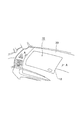
この発明に係る実施例1における助手席用エアバッグ装置は、図示されないエアバッグを内蔵するエアバッグモジュール10をインストルメントパネル20内に装着するようになっている。インストルメントパネル20内に装着されたエアバッグモジュール1は、自動車の前席の一つである助手席に対向配置されている。
In the passenger seat airbag apparatus according to the first embodiment of the present invention, an
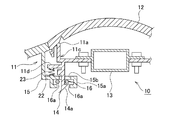
そして、エアバッグモジュール1は、エアバッグを収容し且つエアバッグにおける車室内への開口部11aを上端面に有するケース体11と、開口部11aを閉塞するようにケース体11の上部に一体化されたリッド12と、ケース体11内に配置されてエアバッグを膨張展開するインフレータ13とを、有して構成している。
And the
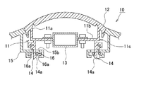
ケース体11は、略四角形の底壁部11bの外周辺部をそれぞれ4つの起立側壁部11cにより囲繞されたボックス形状を呈して構成している。そして、ケース体11の各起立側壁11cには、それぞれ、下方に垂下するフック片14が一体に形成されている。各フック片14は、ケース体11の内部に向かって鉤状に形成されたフック部14aがそれぞれ形成されている。
The
一方、インストルメントパネル20には、助手席に対向する部位において、ケース体11を嵌合設置するためのボックス状の凹陥部21が凹設されている。凹陥部21の底部21aは、中央部を開口させることによって、内方に飛び出すようにフランジ状突出部21bが形成されている。そして、各フランジ状突出部21bの略中央部には、それぞれ、内方に突出するように断面略コ字状を呈する被係合体取付け部15が形成されており、被係合体取付け部15は、インストルメントパネル20側の固定部位を構成している。
On the other hand, the
更に、被係合体取付け部15は、凹陥部21の内方に互いに離間対向する状態で延在する一対の腕部15aを有しており、両腕部15aには、金属製の針金を折曲成形することにより形成したU字状ピン16が挿入設置されている。U字状ピン16は、両脚片部16aが被係合体取付け部15において両腕部15aに挟まれて形成された窓部15bから顕出しており、フック片14が係合する被係合体を構成している。
Further, the engaged
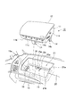
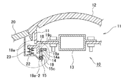
次に、上記のように構成する実施例1において、エアバッグモジュール10をインストルメントパネル20に装着するには、図2示すように、エアバッグモジュール10をインストルメントパネル20の上部より移動して、凹陥部21内に嵌合する。この結果、各フック片14が窓部15bからU字状ピン16の両脚片部16aの間に挿入されることになる。この際、U字状ピン16には、弾性力を有していることから、両脚片部16a間にフック片14が挿入された場合、その付勢力に抗して両脚片部16a間を押し開き、フック片14のフック部14aが挿通した後に元の位置に復帰することになる。この時、フック片14のフック部14aは、一対の脚片部16aの一方に係合することになって、エアバッグモジュール10は、図1に示すように、インストルメントパネル20に装着されることになる。
Next, in the first embodiment configured as described above, in order to attach the
このようにインストルメントパネル20に装着されたエアバッグモジュール10にもしインストルメントパネル20の上部側から物体が当たって所定の力で当接したような場合には、エアバッグモジュール10は、インストルメントパネル20に対して下方方向の力を受けることになる。この結果、ケース体11に形成したフック片14は、被係合体としてのU字状ピン16の両脚片部16a間を可動して、ケース体11をインストルメントパネル20に対して下方向に移動して少しく逃げることができることになって、物体の衝撃を緩和することができる。
In this way, if the object hits the
このように構成する実施例1においては、エアバッグが収容されたケース体11は、フック片14と被係合体としてのU字状ピン16との係合によって、インストルメントパネル20の固定部位である被係合体取付け部15に設置するように構成していることから、従来のブラケットやスティフナを用いず、車両の軽量化を果たすことができる。しかも、フック片14とU字状ピン16とを可動可能に係合するということは、ケース体11をインストルメントパネル20に対してフローティング状態に設置されていることになり、ケース体11をインストルメントパネル20に対して下方向に逃げる構成となっていることになる。
In the first embodiment configured as described above, the
また、実施例1においては、被係合体として、金属製のU字状ピン16にて構成したことから、車両の軽量化に資すると共に、U字状ピン16の両脚片部16aのうち一方に対してフック片14が係合状態を保持したままで可動可能に構成することにより、ケース体11をインストルメントパネル20に対するフローティング状態に設置する構成が、多大な設計工数や実験工数を費やすことなく簡単に実現されることができる。
Moreover, in Example 1, since it comprised with the metal
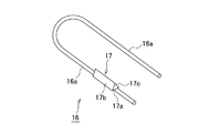
図5は、上記実施例1におけるU字状ピン16の変形例を示している。図5によれば、U字状ピン16は、その外周に樹脂成形品などの被係合片17を装着することによって構成している。被係合片17は、3つの傾斜面部17a、17b及び17cが組み合わさった略三角棒状を呈して構成しており、3つの傾斜面部17a、17b及び17のうち、傾斜面部17aは、下向き面となっているも、傾斜面部17b及び17cは、上向きの傾斜面となっている。かかる2つの傾斜面部17b、17cのうち、一方の傾斜面部17bは、フック片14が係合してきた際には、フック片係合解除動作方向に移動させる傾斜角度を有する係合解除傾斜面に構成されている。
FIG. 5 shows a modification of the
そして、フック片14が被係合片17に対して挿入されてきた際には、フック片14は、まず傾斜面部17bによってフック片係合解除動作方向に移動して押し広げられ、かかる傾斜面部17bをフック片14が乗り越えた後には、フック片14の弾性復帰力によって、下方を向いている被係合傾斜面部としての傾斜面部17aに係合して、ケース体11をインストルメントパネル20に装着することになる。
When the
このようにインストルメントパネル20に装着されたエアバッグモジュール10にもしインストルメントパネル20の上部側から物体が当たって所定の力で当接したような場合には、エアバッグモジュール10は、インストルメントパネル20に対して下方方向の力を受けることになるが、この場合、ケース体11に形成したフック片14は、被係合体としてのU字状ピン16に装着した被係合片17の傾斜面部17aより下方に可動して、ケース体11をインストルメントパネル20に対して下方向に移動させて少しく逃げることができることになって、物体の衝撃を緩和することができる。
In this way, if the object hits the
従って、かかる変形例においては、三角棒を呈する被係合片17の傾斜面部17bは、フック片14の係合動作を円滑にすることができ、フック片14の被係合傾斜面部である傾斜面部17aへの係合を係合動作途中における引っ掛りを生じさせることなく容易にすることができる。
Therefore, in such a modified example, the
そして、かかる変形例においても、実施例1と同様に、エアバッグが収容されたケース体11は、フック片14と被係合体としてのU字状ピン16に装着された被係合片17との係合によって、インストルメントパネル20の固定部位である被係合体取付け部15に設置するように構成している。このことから、かかる変形例も、従来のブラケットやスティフナを用いず、車両の軽量化を果たすことができ、しかも、フック片14と被係合片17とを可動可能に係合することにより、ケース体11をインストルメントパネル20に対してフローティング状態に設置されていることになり、ケース体11をインストルメントパネル20に対して下方向に逃げる構成を実現している。
Also in this modified example, as in the first embodiment, the
また、変形例においても、被係合体として、金属製のU字状ピン16及びこれに装着した合成樹脂性などの被係合片17にて構成したことから、車両の軽量化に資すると共に、被係合片の傾斜面部17aに対してフック片14が係合状態を保持したままで可動可能に構成することにより、ケース体11をインストルメントパネル20に対するフローティング状態に設置する構成が、多大な設計工数や実験工数を費やすことなく簡単に実現されることができる。
Further, in the modified example, as the engaged body, the metal
図6は、上記実施例1の他の変形例を示している。図6によれば、ケース体11の各起立側壁11cにおいて、フック片14の外方に張り出すように上部スプリング座11dが形成されていると共に、インストルメントパネル20の被係合体取付け部15が下部スプリング座22を有して構成されていて、上部スプリング座11dと下部スプリング座22との間に、スプリング23が縮設されている。
FIG. 6 shows another modification of the first embodiment. According to FIG. 6, the
従って、スプリング23の付勢力は、U字状ピン16に対するフック片14の係合関係を保持していることから、インストルメントパネル20に対してケース体11が不用意に取り外されることがない。
Accordingly, since the biasing force of the
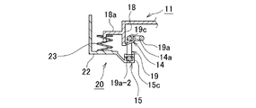
次に、図7から図11を用いて、本発明に係る実施例2について説明する。実施例2においては、図7に示すように、ケース体11の下面から下向きに垂下するように複数の垂下片18を垂設している。垂下片18には、ケース体11の内方に延在するフック片14が形成されており、フック片14の先端部は、上方に向かって鉤状に折曲されてフック部14aを形成している。また、垂下片18には、ケース体11の外方に向かって突出する上部スプリング座18aが形成されている。上部スプリング座18aに対して、離間対向するように、インストルメントパネル20の下面には、略L字状の下部スプリング座22が垂設されている。下部スプリング座22と上部スプリング座18aとの間には、スプリング23が縮設されている。
Next,
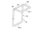
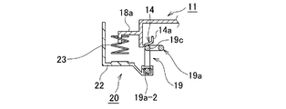
更に、下部スプリング座22は、ケース体内方に突出した被係合体取付け部15を形成されており、被係合体取付け部15には、ベルクランク状に屈曲形成された被係合片19が揺動可能に設置されている。被係合片19は、図11に示すように、金属製の断面丸型針金をその両端部同士を溶接などにより接合した後ループ状に形成すると共に略ベルクランク状に折曲した枠状部19aと、一対の折曲部19b間を橋渡しするように溶接などにより接合装着した係合部19cとを有して構成している。被係合片19の枠状部19aにおける互いに対向する一対の側端片部19a−1、19a−2のうち、下方の側端片部19a−2は、被係合体取付け部15を枠状に形成することにより枢支部15cに揺動可能に枢着されている。また、係合部19cは、フック片14に上部側から係合するように構成されている。
Further, the
このように構成する本発明の実施例2によれば、インストルメントパネル20にケース体11を装着するには、エアバッグモジュール10をインストルメントパネル20の上部より移動して、図9に示すように、フック片の下面に被係合片19の係合部19cを当接する。かかる状態から、更にケース体11をスプリング23の付勢力に抗して下方に移動すると、被係合片19は、枢支部15cに対して側端片部19a−2が摺動して、図10に示すように、図中時計方向に揺動することになる。そして更に、スプリング22の付勢力に抗してケース体11を下動すると、被係合片19の係合部19cが、フック片14のフック部14aを乗り越すことになる。この結果、被係合片19が図中反時計方向に揺動して、フック片14に係合することになって(図8に示す状態)、エアバッグモジュール10は、図7に示すように、インストルメントパネル20に装着されることになる。
According to the second embodiment of the present invention configured as described above, in order to attach the
かかる状態において、ケース体11側の上部スプリング座18aとインストルメントパネル20の固定部位である係合体取付け部15が形成された下部スプリング座22との間に、スプリング23を介在させて、スプリング23の付勢力により被係合片17に対するフック片14の係合関係を助成するように構成されていることになる。従って、被係合片17に対するフック片14の係合関係をスプリング23の付勢力により保持していることから、インストルメントパネル20に対してケース体11が不用意に取り外されることがない。
In such a state, the
更に、実施例2においても、上記実施例1と同様に、インストルメントパネル20に装着されたエアバッグモジュール10にもしインストルメントパネル20の上部側から物体が当たって所定の力で当接したような場合には、エアバッグモジュール10は、インストルメントパネル20に対して下方方向の力を受けることになるが、この場合、ケース体11に形成したフック片14は、被係合片19の係合部19cに対して可動して、ケース体11をインストルメントパネル20に対して下方向に移動して少しく沈ませることができることになって、物体の衝撃を緩和することができる。
Furthermore, also in the second embodiment, as in the first embodiment, the
また、実施例2においても、エアバッグが収容されたケース体11は、フック片14と金属製の針金で構成した被係合片19との係合によって、インストルメントパネル20の固定部位である被係合体取付け部15を形成する下部スプリング座22に設置するように構成していることから、従来のブラケットやスティフナを用いず、車両の軽量化を果たすことができ、しかも、フック片14と被係合片19の係合部19cとを可動可能に係合することにより、ケース体11をインストルメントパネル20に対してフローティング状態に設置されていることになり、ケース体11をインストルメントパネル20に対して下方向に逃げる構成を、多大な設計工数や実験工数を費やすことなく簡単に実現されることができる。
Also in the second embodiment, the
また、実施例2においても、被係合体として、金属製の針金で形成した被係合片19にて構成したことから、車両の軽量化に資すると共に、被係合片19の係合部19cに対してフック片14が係合状態を保持したままで可動可能に構成することにより、ケース体11をインストルメントパネル20に対するフローティング状態に設置する構成を、多くの設計や実験工数などをかけることなく簡単に実現することができる。
Also in the second embodiment, the engaged
上記いずれの実施例においても、ケース体11側にフック片14を設けると共に、インストルメントパネル20側に被係合体としてのU字状ピン16や被係合片19を設けるようにしたが、これに限定されるものでなく、ケース体11側に被係合体としてのU字状ピン16や被係合片19を設けると共に、インストルメントパネル20側にフック片14を設けるようにしてもよい。
In any of the above embodiments, the
この発明は、エアバッグが収容されたケース体を、フック片と被係合体との係合によって、インストルメントパネルの固定部位に設置するように構成しているために、従来のブラケットやスティフナを用いず、車両の軽量化を果たすことができ、しかも、フック片と被係合体とを可動可能に係合することにより、自動車のインストルメントパネルにおける助手席に対向する部位に設置される助手席用エアバッグ装置等に好適であるといえる。 In the present invention, since the case body in which the airbag is accommodated is configured to be installed at the fixed portion of the instrument panel by the engagement between the hook piece and the engaged body, the conventional bracket or stiffener is provided. The passenger seat can be reduced in weight without being used, and is installed at a position facing the passenger seat in the instrument panel of the automobile by movably engaging the hook piece and the engaged body. It can be said that it is suitable for an air bag apparatus for use.
10 エアバッグモジュール
11 ケース体
14 フック片
15 被係合体取付け部(固定部位)
16 U字状ピン(被係合体)
17 被係合片
18 垂下片
18a 上部スプリング座
19 被係合片
19c 係合部
20 インストルメントパネル
22 下部スプリング座
23 スプリング
DESCRIPTION OF
16 U-shaped pin (engaged body)
17
Claims (5)
Priority Applications (1)
| Application Number | Priority Date | Filing Date | Title |
|---|---|---|---|
| JP2011005234A JP2012144193A (en) | 2011-01-13 | 2011-01-13 | Airbag device for passenger seat |
Applications Claiming Priority (1)
| Application Number | Priority Date | Filing Date | Title |
|---|---|---|---|
| JP2011005234A JP2012144193A (en) | 2011-01-13 | 2011-01-13 | Airbag device for passenger seat |
Publications (1)
| Publication Number | Publication Date |
|---|---|
| JP2012144193A true JP2012144193A (en) | 2012-08-02 |
Family
ID=46788230
Family Applications (1)
| Application Number | Title | Priority Date | Filing Date |
|---|---|---|---|
| JP2011005234A Pending JP2012144193A (en) | 2011-01-13 | 2011-01-13 | Airbag device for passenger seat |
Country Status (1)
| Country | Link |
|---|---|
| JP (1) | JP2012144193A (en) |
Cited By (1)
| Publication number | Priority date | Publication date | Assignee | Title |
|---|---|---|---|---|
| JP2016068849A (en) * | 2014-09-30 | 2016-05-09 | 日本プラスト株式会社 | Air bag device |
Citations (8)
| Publication number | Priority date | Publication date | Assignee | Title |
|---|---|---|---|---|
| JPS52171520U (en) * | 1976-06-16 | 1977-12-27 | ||
| JPS62115366U (en) * | 1986-01-16 | 1987-07-22 | ||
| JPH10500922A (en) * | 1995-02-06 | 1998-01-27 | ペトリ アクチエンゲゼルシャフト | Device for fixing the airbag casing consisting of the casing bottom and casing lid to the steering wheel |
| JP2005511407A (en) * | 2001-12-18 | 2005-04-28 | オートリブ デベロップメント アクテボラゲット | Steering wheel mechanism |
| JP2007050876A (en) * | 2005-03-16 | 2007-03-01 | Takata Corp | Steering wheel with airbag apparatus |
| JP2010083243A (en) * | 2008-09-30 | 2010-04-15 | Nippon Plast Co Ltd | Mounting structure of airbag module |
| JP2010254145A (en) * | 2009-04-24 | 2010-11-11 | Nippon Plast Co Ltd | Steering wheel structure |
| JP2010540346A (en) * | 2007-10-02 | 2010-12-24 | オートリブ エーエスピー,インコーポレイティド | Airbag module assembly for controlling the gap near the airbag cover |
-
2011
- 2011-01-13 JP JP2011005234A patent/JP2012144193A/en active Pending
Patent Citations (8)
| Publication number | Priority date | Publication date | Assignee | Title |
|---|---|---|---|---|
| JPS52171520U (en) * | 1976-06-16 | 1977-12-27 | ||
| JPS62115366U (en) * | 1986-01-16 | 1987-07-22 | ||
| JPH10500922A (en) * | 1995-02-06 | 1998-01-27 | ペトリ アクチエンゲゼルシャフト | Device for fixing the airbag casing consisting of the casing bottom and casing lid to the steering wheel |
| JP2005511407A (en) * | 2001-12-18 | 2005-04-28 | オートリブ デベロップメント アクテボラゲット | Steering wheel mechanism |
| JP2007050876A (en) * | 2005-03-16 | 2007-03-01 | Takata Corp | Steering wheel with airbag apparatus |
| JP2010540346A (en) * | 2007-10-02 | 2010-12-24 | オートリブ エーエスピー,インコーポレイティド | Airbag module assembly for controlling the gap near the airbag cover |
| JP2010083243A (en) * | 2008-09-30 | 2010-04-15 | Nippon Plast Co Ltd | Mounting structure of airbag module |
| JP2010254145A (en) * | 2009-04-24 | 2010-11-11 | Nippon Plast Co Ltd | Steering wheel structure |
Cited By (1)
| Publication number | Priority date | Publication date | Assignee | Title |
|---|---|---|---|---|
| JP2016068849A (en) * | 2014-09-30 | 2016-05-09 | 日本プラスト株式会社 | Air bag device |
Similar Documents
| Publication | Publication Date | Title |
|---|---|---|
| CN101821136B (en) | Airbag module | |
| JP2009126466A (en) | Console box structure | |
| CN103958285B (en) | Preposition airbag apparatus | |
| JP5621543B2 (en) | Mounting structure of central module to steering wheel and steering wheel | |
| JP5583774B2 (en) | Installation structure of airbag device for driver's seat | |
| JP2020026263A (en) | Damper mechanism of steering wheel and vehicle steering wheel device | |
| JP5096895B2 (en) | Wire harness protector | |
| JP2012144193A (en) | Airbag device for passenger seat | |
| JP2009029328A (en) | Trim clip suitable for trim for curtain side air bag | |
| CN101374702A (en) | Pedestrian airbag device | |
| JP6385563B2 (en) | Detachment device for airbag device | |
| JP6439228B2 (en) | Door trim for vehicle door | |
| JP5875025B2 (en) | Vehicle ceiling structure and plate used therefor | |
| JP2015151117A (en) | air bag device | |
| JP6215627B2 (en) | Internal parts for vehicles | |
| WO2013008854A1 (en) | Airbag device | |
| JP6551367B2 (en) | Airbag device | |
| JP5656510B2 (en) | Airbag module mounting structure | |
| WO2015125598A1 (en) | Airbag apparatus | |
| JP2012218542A (en) | Airbag apparatus for passenger seat | |
| US20200290546A1 (en) | Knee airbag unit of a vehicle occupant restraint system of a motor vehicle | |
| JP2012192803A (en) | Vehicle seat | |
| JP2003025943A (en) | Air bag system | |
| JP2013248963A (en) | Vehicle interior trim member | |
| JP5425536B2 (en) | Mounting structure for vehicle airbag device |
Legal Events
| Date | Code | Title | Description |
|---|---|---|---|
| A621 | Written request for application examination |
Free format text: JAPANESE INTERMEDIATE CODE: A621 Effective date: 20140113 |
|
| A977 | Report on retrieval |
Free format text: JAPANESE INTERMEDIATE CODE: A971007 Effective date: 20140724 |
|
| A131 | Notification of reasons for refusal |
Free format text: JAPANESE INTERMEDIATE CODE: A131 Effective date: 20140819 |
|
| A02 | Decision of refusal |
Free format text: JAPANESE INTERMEDIATE CODE: A02 Effective date: 20150407 |