JP2012144222A - Vehicular air-conditioning device - Google Patents
Vehicular air-conditioning device Download PDFInfo
- Publication number
- JP2012144222A JP2012144222A JP2011006181A JP2011006181A JP2012144222A JP 2012144222 A JP2012144222 A JP 2012144222A JP 2011006181 A JP2011006181 A JP 2011006181A JP 2011006181 A JP2011006181 A JP 2011006181A JP 2012144222 A JP2012144222 A JP 2012144222A
- Authority
- JP
- Japan
- Prior art keywords
- cooling water
- liquid
- inlet side
- side tank
- heat exchange
- Prior art date
- Legal status (The legal status is an assumption and is not a legal conclusion. Google has not performed a legal analysis and makes no representation as to the accuracy of the status listed.)
- Granted
Links
Images


Classifications
-
- F—MECHANICAL ENGINEERING; LIGHTING; HEATING; WEAPONS; BLASTING
- F01—MACHINES OR ENGINES IN GENERAL; ENGINE PLANTS IN GENERAL; STEAM ENGINES
- F01P—COOLING OF MACHINES OR ENGINES IN GENERAL; COOLING OF INTERNAL-COMBUSTION ENGINES
- F01P3/00—Liquid cooling
- F01P3/02—Arrangements for cooling cylinders or cylinder heads
-
- B—PERFORMING OPERATIONS; TRANSPORTING
- B60—VEHICLES IN GENERAL
- B60H—ARRANGEMENTS OF HEATING, COOLING, VENTILATING OR OTHER AIR-TREATING DEVICES SPECIALLY ADAPTED FOR PASSENGER OR GOODS SPACES OF VEHICLES
- B60H1/00—Heating, cooling or ventilating devices
- B60H1/00321—Heat exchangers for air-conditioning devices
- B60H1/00328—Heat exchangers for air-conditioning devices of the liquid-air type
-
- F—MECHANICAL ENGINEERING; LIGHTING; HEATING; WEAPONS; BLASTING
- F28—HEAT EXCHANGE IN GENERAL
- F28D—HEAT-EXCHANGE APPARATUS, NOT PROVIDED FOR IN ANOTHER SUBCLASS, IN WHICH THE HEAT-EXCHANGE MEDIA DO NOT COME INTO DIRECT CONTACT
- F28D1/00—Heat-exchange apparatus having stationary conduit assemblies for one heat-exchange medium only, the media being in contact with different sides of the conduit wall, in which the other heat-exchange medium is a large body of fluid, e.g. domestic or motor car radiators
- F28D1/02—Heat-exchange apparatus having stationary conduit assemblies for one heat-exchange medium only, the media being in contact with different sides of the conduit wall, in which the other heat-exchange medium is a large body of fluid, e.g. domestic or motor car radiators with heat-exchange conduits immersed in the body of fluid
- F28D1/04—Heat-exchange apparatus having stationary conduit assemblies for one heat-exchange medium only, the media being in contact with different sides of the conduit wall, in which the other heat-exchange medium is a large body of fluid, e.g. domestic or motor car radiators with heat-exchange conduits immersed in the body of fluid with tubular conduits
- F28D1/0408—Multi-circuit heat exchangers, e.g. integrating different heat exchange sections in the same unit or heat exchangers for more than two fluids
- F28D1/0426—Multi-circuit heat exchangers, e.g. integrating different heat exchange sections in the same unit or heat exchangers for more than two fluids with units having particular arrangement relative to the large body of fluid, e.g. with interleaved units or with adjacent heat exchange units in common air flow or with units extending at an angle to each other or with units arranged around a central element
- F28D1/0435—Combination of units extending one behind the other
-
- F—MECHANICAL ENGINEERING; LIGHTING; HEATING; WEAPONS; BLASTING
- F28—HEAT EXCHANGE IN GENERAL
- F28D—HEAT-EXCHANGE APPARATUS, NOT PROVIDED FOR IN ANOTHER SUBCLASS, IN WHICH THE HEAT-EXCHANGE MEDIA DO NOT COME INTO DIRECT CONTACT
- F28D1/00—Heat-exchange apparatus having stationary conduit assemblies for one heat-exchange medium only, the media being in contact with different sides of the conduit wall, in which the other heat-exchange medium is a large body of fluid, e.g. domestic or motor car radiators
- F28D1/02—Heat-exchange apparatus having stationary conduit assemblies for one heat-exchange medium only, the media being in contact with different sides of the conduit wall, in which the other heat-exchange medium is a large body of fluid, e.g. domestic or motor car radiators with heat-exchange conduits immersed in the body of fluid
- F28D1/04—Heat-exchange apparatus having stationary conduit assemblies for one heat-exchange medium only, the media being in contact with different sides of the conduit wall, in which the other heat-exchange medium is a large body of fluid, e.g. domestic or motor car radiators with heat-exchange conduits immersed in the body of fluid with tubular conduits
- F28D1/053—Heat-exchange apparatus having stationary conduit assemblies for one heat-exchange medium only, the media being in contact with different sides of the conduit wall, in which the other heat-exchange medium is a large body of fluid, e.g. domestic or motor car radiators with heat-exchange conduits immersed in the body of fluid with tubular conduits the conduits being straight
- F28D1/0535—Heat-exchange apparatus having stationary conduit assemblies for one heat-exchange medium only, the media being in contact with different sides of the conduit wall, in which the other heat-exchange medium is a large body of fluid, e.g. domestic or motor car radiators with heat-exchange conduits immersed in the body of fluid with tubular conduits the conduits being straight the conduits having a non-circular cross-section
- F28D1/05366—Assemblies of conduits connected to common headers, e.g. core type radiators
-
- F—MECHANICAL ENGINEERING; LIGHTING; HEATING; WEAPONS; BLASTING
- F28—HEAT EXCHANGE IN GENERAL
- F28F—DETAILS OF HEAT-EXCHANGE AND HEAT-TRANSFER APPARATUS, OF GENERAL APPLICATION
- F28F9/00—Casings; Header boxes; Auxiliary supports for elements; Auxiliary members within casings
- F28F9/02—Header boxes; End plates
-
- F—MECHANICAL ENGINEERING; LIGHTING; HEATING; WEAPONS; BLASTING
- F01—MACHINES OR ENGINES IN GENERAL; ENGINE PLANTS IN GENERAL; STEAM ENGINES
- F01P—COOLING OF MACHINES OR ENGINES IN GENERAL; COOLING OF INTERNAL-COMBUSTION ENGINES
- F01P3/00—Liquid cooling
- F01P3/02—Arrangements for cooling cylinders or cylinder heads
- F01P2003/027—Cooling cylinders and cylinder heads in parallel
-
- F—MECHANICAL ENGINEERING; LIGHTING; HEATING; WEAPONS; BLASTING
- F28—HEAT EXCHANGE IN GENERAL
- F28D—HEAT-EXCHANGE APPARATUS, NOT PROVIDED FOR IN ANOTHER SUBCLASS, IN WHICH THE HEAT-EXCHANGE MEDIA DO NOT COME INTO DIRECT CONTACT
- F28D1/00—Heat-exchange apparatus having stationary conduit assemblies for one heat-exchange medium only, the media being in contact with different sides of the conduit wall, in which the other heat-exchange medium is a large body of fluid, e.g. domestic or motor car radiators
- F28D1/02—Heat-exchange apparatus having stationary conduit assemblies for one heat-exchange medium only, the media being in contact with different sides of the conduit wall, in which the other heat-exchange medium is a large body of fluid, e.g. domestic or motor car radiators with heat-exchange conduits immersed in the body of fluid
- F28D2001/0253—Particular components
- F28D2001/026—Cores
Landscapes
- Engineering & Computer Science (AREA)
- Mechanical Engineering (AREA)
- Physics & Mathematics (AREA)
- Thermal Sciences (AREA)
- General Engineering & Computer Science (AREA)
- Chemical & Material Sciences (AREA)
- Combustion & Propulsion (AREA)
- Air-Conditioning For Vehicles (AREA)
Abstract
【課題】加熱用熱交換器を通過後の空調風に生じる左右方向の温度差を低減することができる車両用空調装置を提供する。
【解決手段】第1液体と車室内への送風空気とを熱交換させる第1ヒータコア10と、第1液体よりも高温かつ小流量の第2液体と第1ヒータコア10で加熱された送風空気とを熱交換させる第2ヒータコア20とを備える加熱用熱交換器2を、入口側タンク部22が下、出口側タンク部23が上であって、チューブ21の長手方向が傾斜するように、空調ケース51に保持させる。これにより、第2ヒータコア20に流入した高温の第2液体が、入口側タンク部22内のうち、チューブ21の入口側端部21aよりも上方の領域であって、複数のチューブ21の積層方向全域にわたる貯液部71に貯まった後、複数のチューブ22に流入する構成とする。
【選択図】図2A vehicle air conditioner capable of reducing a temperature difference in the left-right direction generated in air-conditioned air after passing through a heat exchanger for heating is provided.
A first heater core that exchanges heat between a first liquid and air blown into a vehicle interior; a second liquid that is hotter and has a lower flow rate than the first liquid; and air that is heated by the first heater core. The heating heat exchanger 2 including the second heater core 20 for exchanging heat is air-conditioned so that the inlet side tank portion 22 is at the bottom and the outlet side tank portion 23 is at the top, and the longitudinal direction of the tube 21 is inclined. The case 51 is held. Thereby, the high temperature 2nd liquid which flowed into the 2nd heater core 20 is an area | region above the inlet side edge part 21a of the tube 21 among the inlet side tank parts 22, Comprising: The lamination direction of the some tube 21 The liquid is stored in the liquid storage part 71 over the entire area, and then flows into the plurality of tubes 22.
[Selection] Figure 2
Description
本発明は、車室内への送風空気を加熱する加熱用熱交換器を備える車両用空調装置に関するものである。 The present invention relates to a vehicle air conditioner including a heating heat exchanger that heats air blown into a passenger compartment.
このような車両用空調装置として、特許文献1、2に記載のものがある。
There exists a thing of
特許文献1に記載のものでは、エンジン内部の冷却水流路として、シリンダヘッドを冷却するシリンダヘッド側流路とシリンダブロックを冷却するシリンダブロック側流路とがあり、シリンダヘッド側流路を通過した冷却水が1つの加熱用熱交換器に流入する構成となっている。
In the thing of
また、特許文献2に記載のものでは、空気を加熱するための加熱用熱交換器を2つ備え、エンジンに設けられた1つの冷却水出口から流出の冷却水を分流させて、それぞれの加熱用熱交換器に流入させている。
Moreover, in the thing of
ところで、近年では、車両に搭載されるエンジンに対して、要求される出力を確保しつつ、従来よりも小型化させたいという要望がある。これを実現するために、圧縮比を上げたり、過給機付きエンジンでは過給圧を上げたりすると、ノッキングが生じる恐れがあるので、耐ノッキング性能を向上させる必要がある。そこで、耐ノッキング性能を向上させるために、シリンダヘッドを積極的に冷却することが考えられる。 By the way, in recent years, there is a demand for an engine mounted on a vehicle to ensure a required output and to make it smaller than before. In order to realize this, knocking may occur when the compression ratio is increased or when the supercharging pressure is increased in an engine with a supercharger. Therefore, it is necessary to improve anti-knocking performance. Therefore, it is conceivable to positively cool the cylinder head in order to improve the knocking resistance.
ただし、シリンダブロックについてはエンジン内部のフリクション増加を抑制するために、所定温度以上に維持する必要がある。このため、エンジン内部の冷却水流路として、シリンダヘッド側流路と、シリンダブロック側流路とを設け、シリンダヘッド側流路の冷却水流量をシリンダブロック側流路の冷却水流量よりも多くすることが考えられる。 However, the cylinder block needs to be maintained at a predetermined temperature or higher in order to suppress an increase in friction inside the engine. Therefore, a cylinder head side flow path and a cylinder block side flow path are provided as cooling water flow paths inside the engine, and the cooling water flow rate of the cylinder head side flow path is made larger than the cooling water flow rate of the cylinder block side flow path. It is possible.
しかし、この場合、シリンダヘッドを冷却した後の冷却水温度が暖房に必要な最小温度よりも低くなり、特許文献1に記載の技術のように、シリンダヘッドを冷却した冷却水のみを熱源として車室内への送風空気を加熱すると、空気温度を十分に高くできないという問題が生じる。ちなみに、従来では、シリンダヘッドを冷却した後の冷却水温度は、80〜90℃程度であり、暖房に必要な最小温度を超えていたので、このような問題は生じなかった。
However, in this case, the cooling water temperature after cooling the cylinder head becomes lower than the minimum temperature required for heating, and as in the technique described in
そこで、加熱用熱交換器として、シリンダヘッドを冷却した冷却水と送風空気とを熱交換させる第1熱交換部と、シリンダブロックを冷却した冷却水と第1熱交換部で加熱された送風空気とを熱交換させる第2熱交換部とを備える構成とすることが考えられる。 Therefore, as a heat exchanger for heating, the first heat exchange unit that exchanges heat between the cooling water that has cooled the cylinder head and the blown air, and the blown air that is heated by the cooling water that has cooled the cylinder block and the first heat exchange unit And a second heat exchanging part that exchanges heat with each other.
これによれば、第1熱交換部において、シリンダブロックを冷却した冷却水を熱源として、送風空気を加熱した後、第2熱交換部において、シリンダヘッド冷却後の冷却水よりも高温であるシリンダブロック冷却後の冷却水を熱源として、第1熱交換部で加熱された送風空気をさらに加熱するので、加熱用熱交換器通過後の空気温度を十分に高くすることができる。 According to this, in the first heat exchanging unit, the cooling air that has cooled the cylinder block is used as a heat source, and the blown air is heated, and then in the second heat exchanging unit, the cylinder that is hotter than the cooling water after cooling the cylinder head Since the blown air heated by the first heat exchange unit is further heated using the cooling water after block cooling as a heat source, the air temperature after passing through the heating heat exchanger can be sufficiently increased.
しかし、この場合、シリンダブロック側流路の冷却水流量は、シリンダヘッド側流路の冷却水流量よりも少ないので、第2熱交換部に流入する冷却水は第1熱交換部に流入する冷却水よりも小流量となる。このため、下記の通り、加熱用熱交換器通過後の空調風に左右方向の温度差が大きな温度分布が生じてしまうことがわかった。 However, in this case, since the cooling water flow rate in the cylinder block side flow path is smaller than the cooling water flow rate in the cylinder head side flow path, the cooling water flowing into the second heat exchange unit is cooled into the first heat exchange unit. The flow rate is smaller than that of water. For this reason, it turned out that the temperature distribution with a large temperature difference of the left-right direction will arise in the air-conditioning wind after passing through the heat exchanger for heating as follows.
すなわち、第2熱交換部は、積層された複数のチューブと、複数のチューブの長手方向一端側に連通し、冷却水入口側となる入口側タンク部と、複数のチューブの長手方向他端側に連通し、冷却水出口側となる出口側タンク部とを備える構成である。この第2熱交換部を、入口側タンク部が下側に位置し、出口側タンク部が上側に位置するように空調ケースに保持させて、第2熱交換部内に冷却水を下から上に流す場合、入口側タンク部に流入した冷却水の多くが、冷却水入口に近いチューブを流れ、冷却水入口から遠いチューブまで冷却水が流れ難いという現象が生じてしまうことがわかった。 That is, the second heat exchanging unit communicates with the stacked tubes, the one end side in the longitudinal direction of the plurality of tubes, and the inlet side tank unit serving as the cooling water inlet side, and the other end side in the longitudinal direction of the plurality of tubes And an outlet side tank portion which is the cooling water outlet side. This second heat exchange part is held in the air conditioning case so that the inlet side tank part is located on the lower side and the outlet side tank part is located on the upper side, and the cooling water is moved from the bottom to the upper part in the second heat exchange part. When flowing, it has been found that a phenomenon occurs in which most of the cooling water flowing into the inlet side tank portion flows through the tube close to the cooling water inlet and the cooling water hardly flows from the cooling water inlet to the tube far from the cooling water inlet.
これは、次の理由のためである。一般的に、液体内において、その下側に高温部分が存在する場合、その高温部分は浮力によって上昇する。そして、第2熱交換部では、冷却水がチューブ内を空気と熱交換しながら流れるので、入口側タンク部に流入した冷却水の方が出口側タンク部内の冷却水よりも温度が高い。このため、入口側タンク部に流入した高温の冷却水は、浮力の影響を受けることとなり、さらに、第2熱交換部に流入する冷却水が、第1熱交換部に流入する冷却水よりも小流量で低流速になると、この浮力の影響が大きくなるからである。 This is for the following reason. Generally, in a liquid, when a high temperature part exists under the liquid, the high temperature part rises by buoyancy. And in the 2nd heat exchange part, since cooling water flows while exchanging heat with air in a tube, the temperature of the cooling water which flowed into the entrance side tank part is higher than the cooling water in the exit side tank part. For this reason, the high-temperature cooling water that has flowed into the inlet side tank unit is affected by buoyancy, and the cooling water that flows into the second heat exchange unit is more than the cooling water that flows into the first heat exchange unit. This is because the influence of this buoyancy increases when the flow rate is low and the flow rate is low.
加熱用熱交換器通過後の空調風に左右方向の温度差が大きな温度分布が生じてしまうと、例えば、加熱用熱交換器通過後の空調風が車両左右方向の一方側と他方側に分岐して、運転席側の吹出口、助手席側の吹出口から空調風が吹き出される場合に、運転席側、助手席側での吹出空気温度に差が生じてしまう。 If temperature distribution with a large temperature difference in the left-right direction occurs in the conditioned air after passing through the heat exchanger for heating, for example, the conditioned air after passing through the heat exchanger for heating branches to one side and the other side in the vehicle left-right direction. Thus, when the conditioned air is blown out from the air outlet on the driver's seat side and the air outlet on the passenger seat side, there is a difference in the air temperature between the driver's seat side and the passenger seat side.
なお、このような問題は、第1熱交換部がシリンダヘッド冷却後の冷却水を熱源とし、第2熱交換部がシリンダブロック冷却後の冷却水を熱源とする場合に限らず、第1熱交換部が第1液体を熱源とし、第2熱交換部が第1液体よりも高温かつ小流量の第2液体を熱源とする場合に生じる問題である。 Such a problem is not limited to the case where the first heat exchange unit uses the cooling water after cooling the cylinder head as a heat source, and the second heat exchange unit uses the cooling water after cooling the cylinder block as a heat source. This is a problem that occurs when the exchange unit uses the first liquid as the heat source, and the second heat exchange unit uses the second liquid having a higher temperature and a lower flow rate than the first liquid as the heat source.
本発明は上記点に鑑みて、加熱用熱交換器を通過後の空調風に生じる左右方向の温度差を低減することができる車両用空調装置を提供することを目的とする。 An object of this invention is to provide the vehicle air conditioner which can reduce the temperature difference of the left-right direction produced in the air-conditioning wind after passing through the heat exchanger for heating in view of the said point.
上記目的を達成するため、請求項1に記載の発明では、第2熱交換部(20)は、入口側タンク部(22)に流入した第2液体であって、出口側タンク部(23)内の液体よりも高温の液体が、複数のチューブ(21)の積層方向全域にわたる入口側タンク部内の貯液部(71、72、73、74)に貯まった後、複数のチューブ(21)に流入する構成となっていることを特徴としている。 In order to achieve the above object, according to the first aspect of the present invention, the second heat exchange section (20) is the second liquid flowing into the inlet side tank section (22), and the outlet side tank section (23). After the liquid having a temperature higher than that in the liquid is stored in the liquid storage sections (71, 72, 73, 74) in the inlet side tank section over the entire stacking direction of the plurality of tubes (21), the liquid is stored in the plurality of tubes (21). It is characterized by an inflowing configuration.
本発明によれば、このような構成を採用しているので、第2熱交換部を流れる第2液体が、第1熱交換部を流れる第1液体よりも低流速であっても、複数のチューブを流れる冷却水の温度差を低減でき、加熱用熱交換器を通過後の空調風に生じる左右方向の温度差を低減することができる。 According to the present invention, since such a configuration is adopted, even if the second liquid flowing through the second heat exchange unit has a lower flow velocity than the first liquid flowing through the first heat exchange unit, The temperature difference of the cooling water flowing through the tube can be reduced, and the temperature difference in the left-right direction generated in the conditioned air after passing through the heat exchanger for heating can be reduced.
貯液部については、例えば、請求項2〜4に記載の形成手法を採用できる。
For the liquid storage part, for example, the formation method described in
すなわち、請求項2に記載の発明のように、第2熱交換部(20)を傾斜させることで、入口側タンク部(22)内のうち、チューブ(21)の入口側端部(21a)よりも上方の領域に貯液部(71)を形成することができる。
That is, as in the invention described in
また、請求項3に記載の発明のように、入口側タンク部(22)を構成する壁の一部(91)を、他の部分よりも外側に膨らませることで貯液部(72)を形成することができる。 Further, as in the third aspect of the invention, the liquid storage part (72) is formed by inflating a part (91) of the wall constituting the inlet side tank part (22) outside the other part. Can be formed.
また、請求項4に記載の発明のように、第2熱交換部(20)の入口側タンク部(22)内に挿入されているチューブ(21)の挿入長さ(84)を、第1熱交換部(10)の入口側タンク部(12)内に挿入されているチューブ(11)の挿入長さ(85)よりも長くすることで、第2熱交換部(10)の入口側タンク部(22)内のうち、チューブ(21)の入口側端部(21a)よりも重力方向上方の領域に貯液部(74)を形成することができる。
Further, as in the invention described in
ところで、第2熱交換部(20)の入口側タンク部(22)における液体導入路の末端開口部(20a)を入口側タンク部(22)の長手方向に投影したときにおいて、液体導入路の末端開口部(20a)が、チューブ(21)の入口の真下に位置する場合、入口側タンク部に流入した高温の液体は、浮力によって上昇するため、入口側タンク部に高温の液体が流入したとき、流入した液体の上方に位置するチューブに高温の液体が流入してしまう。 By the way, when the terminal opening (20a) of the liquid introduction path in the inlet side tank section (22) of the second heat exchange section (20) is projected in the longitudinal direction of the inlet side tank section (22), the liquid introduction path When the end opening (20a) is located directly below the inlet of the tube (21), the high-temperature liquid flowing into the inlet-side tank rises due to buoyancy, so the high-temperature liquid flows into the inlet-side tank. At that time, the high-temperature liquid flows into the tube located above the inflowing liquid.
そこで、請求項5に記載の発明では、請求項1〜4に記載の発明において、液体導入路の末端開口部(20a)の少なくとも一部が、チューブ(21)の入口の重力方向での真下を除く位置にあることを特徴としている。
Therefore, in the invention described in
これによれば、液体導入路の末端開口部の一部がチューブの真下の範囲から外れているので、液体導入路の末端開口部から流入した高温の第2液体の一部を確実に貯液部に導くことができる。 According to this, since a part of the end opening of the liquid introduction path is out of the range directly below the tube, a part of the high temperature second liquid flowing in from the end opening of the liquid introduction path is reliably stored. Can be led to the department.
液体導入路の末端開口部(20a)の少なくとも一部が、チューブ(21)の入口の真下を除く位置にある構成としては、例えば、請求項6に記載の発明のように、液体導入路の末端開口部(20a)の少なくとも一部が、チューブ(21)の入口側端部(21a)でのチューブ(21)の内壁(21b)から重力方向に平行に引いた2本の仮想線(81、82)の間よりも外側に位置する構成を採用できる。また、請求項7に記載の発明のように、液体導入路の末端開口部(20a)の少なくとも一部が、チューブ(21)の入口側端辺(21a)を通る仮想線(83)よりも上側に位置する構成を採用できる。なお、請求項6、7の両方に記載の構成を採用することもできる。
As a configuration in which at least a part of the terminal opening (20a) of the liquid introduction path is located at a position excluding just below the inlet of the tube (21), for example, as in the invention according to claim 6, Two imaginary lines (81) in which at least a part of the end opening (20a) is drawn in parallel to the direction of gravity from the inner wall (21b) of the tube (21) at the inlet end (21a) of the tube (21). , 82), a configuration located outside can be employed. Further, as in the invention described in
また、請求項5〜7に記載の発明においては、請求項8に記載の発明のように、液体導入路の末端開口部(20a)の全面積の35%以上の部分が、チューブ(21)の入口の重力方向での真下を除く位置にあることが好ましい。これにより、後述の図10に示すように、加熱用熱交換器からの左右吹出空気の温度差を特に小さくすることができる。
Further, in the inventions according to
また、請求項1〜7に記載の発明においては、請求項9に記載の発明のように、第2熱交換部(20)は、入口側タンク部(22)の長手方向一端側から第2液体が流入するとともに、入口側タンク部(22)の上壁が、入口側タンク部(22)の長手方向一端側よりも長手方向他端側が重力方向上方に位置するように、傾斜した状態で車両に搭載されるようにすることが好ましい。これにより、入口側タンク部の上壁が水平の場合と比較して、貯液部を流れる高温の液体を、入口側タンク部の長手方向他端側に導きやすくなるからである。 Moreover, in invention of Claims 1-7, 2nd heat exchange part (20) is 2nd from the longitudinal direction one end side of an inlet side tank part (22) like invention of Claim 9. While the liquid flows in, the upper wall of the inlet side tank part (22) is inclined so that the other end side in the longitudinal direction is located above the one end side in the longitudinal direction of the inlet side tank part (22). It is preferable to be mounted on a vehicle. This is because it is easier to guide the high-temperature liquid flowing through the liquid storage part to the other end side in the longitudinal direction of the inlet side tank part as compared with the case where the upper wall of the inlet side tank part is horizontal.
また、請求項1〜9に記載の発明においては、さらに、請求項10に記載の発明のように、第2熱交換部(20)の入口側タンク部(22)の内部に、入口側タンク部(22)に流入した第2液体の流速を上昇させる流速上昇手段(92)を設けることができる。
Further, in the inventions according to
これによれば、入口側タンク部に流入した第2液体の流速上昇手段(92)通過後の流速を通過前よりも上昇させることができるので、冷却水の流速を上昇させる手段を設けていない場合と比較して、入口側タンク部の第2液体入口から離れた側まで冷却水を流すことができる。よって、本発明によれば、貯液部を形成した場合よりも、さらに、複数のチューブを流れる冷却水の温度差を低減でき、加熱用熱交換器を通過後の空調風に生じる左右方向の温度差を低減することができる。 According to this, since the flow rate of the second liquid that has flowed into the inlet side tank portion can be increased after the flow rate increasing means (92), the means for increasing the flow rate of the cooling water is not provided. Compared to the case, the cooling water can flow to the side away from the second liquid inlet of the inlet side tank section. Therefore, according to the present invention, the temperature difference between the cooling water flowing through the plurality of tubes can be further reduced as compared with the case where the liquid storage part is formed, and the horizontal direction generated in the conditioned air after passing through the heat exchanger for heating is reduced. A temperature difference can be reduced.
また、請求項1〜10に記載の発明においては、さらに、請求項11に記載の発明のように、第2熱交換部(20)の入口側タンク部(22)の流路断面積を、第1熱交換部(10)のそれよりも小さくしたり、請求項12に記載の発明のように、第2熱交換部(20)の入口側タンク部(22)に第2液体を導入する液体導入路の流路断面積を、第1熱交換部(10)のそれよりも小さくしたり、これらの両方を採用したりすることが好ましい。
Moreover, in invention of Claims 1-10, like the invention of
このようにして、入口側タンク部に流入した第2液体の流速を高めることでも、入口側タンク部の第2液体入口から離れた側まで冷却水を流すことができる。 In this way, the cooling water can be allowed to flow to the side away from the second liquid inlet of the inlet side tank part also by increasing the flow rate of the second liquid flowing into the inlet side tank part.
また、請求項13に記載の発明では、第2熱交換部(20)の入口側タンク部(22)の内部に、入口側タンク部(22)に流入した第2液体の流速を上昇させる流速上昇手段(92)を設けたことを特徴としている。
In the invention according to
これによれば、入口側タンク部に流入した第2液体の流速上昇手段(92)通過後の流速を通過前よりも上昇させることができるので、冷却水の流速を上昇させる手段を設けていない場合と比較して、入口側タンク部の第2液体入口から離れた側まで冷却水を流すことができる。よって、本発明によれば、複数のチューブを流れる冷却水の温度差を低減でき、加熱用熱交換器を通過後の空調風に生じる左右方向の温度差を低減することができる。 According to this, since the flow rate of the second liquid that has flowed into the inlet side tank portion can be increased after the flow rate increasing means (92), the means for increasing the flow rate of the cooling water is not provided. Compared to the case, the cooling water can flow to the side away from the second liquid inlet of the inlet side tank section. Therefore, according to this invention, the temperature difference of the cooling water which flows through a some tube can be reduced, and the temperature difference of the left-right direction produced in the conditioned air after passing through the heat exchanger for heating can be reduced.
なお、請求項10〜13に記載の発明では、第2熱交換部(20)の入口側タンク部(22)を流れる第2液体の流速が、第1熱交換部(10)の入口側タンク部(12)を流れる第1液体の流速と同等以上となるようにすることが好ましい。 In addition, in invention of Claims 10-13, the flow velocity of the 2nd liquid which flows through the inlet side tank part (22) of a 2nd heat exchange part (20) is the inlet side tank of a 1st heat exchange part (10). It is preferable to be equal to or higher than the flow velocity of the first liquid flowing through the portion (12).
なお、この欄および特許請求の範囲で記載した各手段の括弧内の符号は、後述する実施形態に記載の具体的手段との対応関係を示す一例である。 In addition, the code | symbol in the bracket | parenthesis of each means described in this column and the claim is an example which shows a corresponding relationship with the specific means as described in embodiment mentioned later.
以下、本発明の実施形態について図に基づいて説明する。なお、以下の各実施形態相互において、互いに同一もしくは均等である部分には、説明の簡略化を図るべく、図中、同一符号を付してある。 Hereinafter, embodiments of the present invention will be described with reference to the drawings. In the following embodiments, parts that are the same or equivalent to each other are given the same reference numerals in the drawings in order to simplify the description.
(第1実施形態)
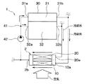
図1に本実施形態における車両用空調装置の概略構成を示す。本実施形態の車両用空調装置は、エンジン(内燃機関)および走行用電動モータから車両走行用の駆動力を得るハイブリッド車に搭載されるものである。
(First embodiment)
FIG. 1 shows a schematic configuration of a vehicle air conditioner in the present embodiment. The vehicle air conditioner of the present embodiment is mounted on a hybrid vehicle that obtains driving force for vehicle travel from an engine (internal combustion engine) and a travel electric motor.
本実施形態の車両用空調装置1は、エンジン30の冷却水と車室内への送風空気とを熱交換させることにより、車室内への送風空気を加熱する加熱用熱交換器2を備えている。なお、冷却水は水もしくは添加成分を含む水である。
The
加熱用熱交換器2は、第1ヒータコア10と第2ヒータコア20とを有し、両者が一体化したものである。第1ヒータコア10、第2ヒータコア20が、それぞれ、本発明における加熱用熱交換器の第1熱交換部、第2熱交換部に相当する。
The
第1ヒータコア10はエンジン30のシリンダヘッド31を冷却した冷却水が流入し、第2ヒータコア20はエンジン30のシリンダブロック32を冷却した冷却水が流入するようになっている。また、第1ヒータコア10は、空気流れ上流側に位置し、第2ヒータコア20は、空気流れ下流側に位置している。
Cooling water that has cooled the
ここで、エンジン30において、シリンダブロック32は、ピストンが往復運動するシリンダボア(円柱状の穴)を構成するブロック体である。シリンダヘッド31は、シリンダボアの上死点側の開口部を閉塞して燃焼室を構成するブロック体である。
Here, in the
エンジン30のシリンダヘッド31側に第1冷却水入口31aと第1出口部としての第1冷却水出口31bとが設けられ、シリンダヘッド31の内部には、シリンダヘッド31を冷却する冷却水が流れるシリンダヘッド側の冷却水流路が形成されている。第1冷却水入口31aから流入した冷却水は、シリンダヘッド31の内部を流れた後、第1冷却水出口31bから流出する。
A first
同様に、エンジン30のシリンダブロック32側に第2冷却水入口32aと第2出口部としての第2冷却水出口32bとが設けられ、シリンダブロック32の内部には、シリンダブロック32を冷却する冷却水が流れるシリンダブロック側の冷却水流路が形成されている。第2冷却水入口32aから流入した冷却水は、シリンダブロック32の内部を流れた後、第2冷却水出口32bから流出する。このように、本実施形態では、シリンダブロック32を冷却した冷却水は、シリンダヘッド31を冷却した冷却水と合流することなく、第2冷却水出口32bから流出する。
Similarly, a second
このように、本実施形態のエンジン30は2つの冷却系統を有している。そして、エンジン30の定常運転時に、シリンダヘッド側の冷却水流路の冷却水流量を、シリンダブロック側の冷却水流路の冷却水流量よりも多くして、シリンダブロック32よりもシリンダヘッド31を積極的に冷却するようになっている。これは、シリンダヘッド31を低温度にすることで、耐ノッキング性能を向上させるとともに、シリンダブロック32を高温度に維持することで、エンジンオイルの低粘度を維持して、エンジン内部のフリクション増加を抑制するためである。
Thus, the
そして、加熱用熱交換器2において、第1ヒータコア10の冷却水入口10aは、エンジン30のシリンダヘッド31側の第1冷却水出口31bに配管を介して連結されており、第1冷却水出口31bから流出の冷却水が第1ヒータコア10に流入する。一方、第2ヒータコア20の冷却水入口20aは、エンジン30のシリンダブロック32側の第2冷却水出口32bに配管を介して連結されており、この第2冷却水出口32bから流出の冷却水が第2ヒータコア20に流入する。
In the
したがって、本実施形態では、第1ヒータコア10に低温かつ大流量の冷却水が流入し、第2ヒータコア20に高温かつ小流量の冷却水が流入する。具体的には、第1ヒータコア10に流入する冷却水の温度および流量は、30〜60℃、5〜15L/minの範囲であり、第2ヒータコア20に流入する冷却水の温度および流量は、40〜90℃、0.2〜3L/minの範囲である。
Therefore, in this embodiment, low temperature and large flow rate cooling water flows into the
第1ヒータコア10および第2ヒータコア20は、後述の通り、それぞれ、独立した熱交換コア部を有している。このため、第1ヒータコア10に流入した冷却水は、第2ヒータコア20に流入した冷却水と混ざることなく、第1ヒータコア10の熱交換コア部で空気と熱交換する。同様に、第2ヒータコア20に流入した冷却水は、第1ヒータコア10に流入した冷却水と混ざることなく、第2ヒータコア20の熱交換コア部で空気と熱交換する。そして、各熱交換コア部を通過した冷却水は、合流した後、加熱用熱交換器2に設けられた共通の冷却水出口2bから流出するようになっている。
As will be described later, each of the
加熱用熱交換器2の冷却水出口2bから流出の冷却水は、分岐部41で分岐して、エンジン30の第1冷却水入口31aと第2冷却水出口32aのそれぞれに流入する。
The cooling water flowing out from the cooling
また、図1に示すように、ウォータポンプ42が、加熱用熱交換器2の冷却水出口2bと分岐部41との間の冷却水流路途中に配置されている。ウォータポンプ42は、冷却水流れを形成するとともに、冷却水流量を調整する調整手段である。ウォータポンプ42は、電動式ポンプであり、図示しない制御装置によって回転数が制御されることで、冷却水流量を制御する。
Further, as shown in FIG. 1, the
なお、エンジン30は、図示しないラジエータと連通しており、シリンダヘッド31から流出の冷却水がラジエータで放熱し、放熱後の冷却水がシリンダヘッド32に流入でき、シリンダブロック32から流出の冷却水がラジエータで放熱し、放熱後の冷却水がシリンダブロック32に流入できるようになっている。
The
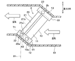
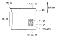
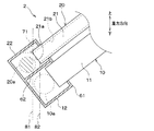
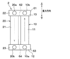
次に、加熱用熱交換器2について詳細に説明する。図2に空調ケース51に保持された状態の加熱用熱交換器2の側面図を示し、図3に空気流れ下流側から見た加熱用熱交換器2の正面図を示す。なお、図中の上下方向の矢印は、車両に搭載された状態での重力方向に対して平行な上下方向を示しており、他の図においても同様である。また、このときの車両は、傾斜面ではなく水平な面上に位置している。
Next, the
図2、3に示すように、加熱用熱交換器2の第1、第2ヒータコア10、20は、ともに、積層された複数本の扁平状のチューブ11、21と、複数本のチューブ11、21の長手方向一端側に連通し、冷却水入口側となる入口側タンク部12、22と、複数本のチューブ11、21の長手方向他端側に連通し、冷却水出口側となる出口側タンク部13、23とを備えている。
As shown in FIGS. 2 and 3, the first and
加熱用熱交換器2は、車室内に向かう送風空気を形成する図示しない送風機とともに空調ケース51に収容されて、車両に搭載されている。具体的には、図2に示すように、加熱用熱交換器2は、傾斜した状態であって、第2ヒータコア20が第1ヒータコア10よりも空気流れ下流側に位置するように、空調ケース51に保持されている。傾斜した状態とは、加熱用熱交換器2の空気流出入面が、鉛直方向と水平方向の両方に平行でなく、空気流出入面と鉛直方向とのなす角度が鋭角となる状態を意味する。また、加熱用熱交換器2の空気流出入面の向きは、加熱用熱交換器2を測方から見たときのチューブ21の長手方向と一致する。本実施形態では、第2ヒータコア20が第1ヒータコア10よりも上方に位置するように、加熱用熱交換器2が傾斜している。このため、第1、第2ヒータコア10、20を通過する空気流れ方向は斜め上方向である。
The
なお、本実施形態では、図3に示すように、第2ヒータコア20を正面から見たとき、第2ヒータコア20の入口側タンク部22の上壁が水平方向に平行となるように、加熱用熱交換器2が車両に搭載されている。
In this embodiment, as shown in FIG. 3, when the
空調ケース51には、図示されていないが、加熱用熱交換器2を迂回して送風空気が流れるバイパス空気通路と、バイパス空気通路の通過後の空気と、加熱用熱交換器2の通過後の空気との混合割合を調整するエアミックスドアとが設けられている。なお、加熱用熱交換器2通過後の空気が流れる空気流路は、その下側がフット吹出口に連なっており、その上側がデフロスタ吹出口、フェイス吹出口に連なっている。
Although not shown in the
第1、第2ヒータコア10、20の入口側タンク部12、22は、1つの入口側タンク61の内部を仕切り壁62によって2つに仕切ることで構成されており、それぞれに、冷却水入口10a、20aが設けられている。冷却水入口10a、20aは、入口側タンク部12、22を構成する壁に形成された開口部であり、入口側タンク部12、22内に面するとともに、入口側タンク部12、22に冷却水を導入する冷却水導入路の末端開口部である。これらの冷却水入口10a、20aは、入口側タンク部12、22のうち、車両左右方向(図3の左右方向)での一端側に配置されている。
The inlet
第1、第2ヒータコア10、20の出口側タンク部13、23は、1つの出口側タンク63で共通化されている。この出口側タンク63には1つの冷却水出口2bが設けられている。このため、出口側タンク63の内部で、第1ヒータコア10に流入した冷却水と、第2ヒータコア20に流入した冷却水とが合流し、合流した冷却水が1つの冷却水出口2bから流出する。なお、冷却水出口2bは、冷却水入口10a、20aと同じ車両左右方向での一端側に配置されている。
The outlet
このように、本実施形態では、第1、第2ヒータコア10、20の出口側タンク部を共通化して、加熱用熱交換器2の冷却水出口2bを1つにしているが、第1、第2ヒータコア10、20のそれぞれに出口側タンク部および冷却水出口を設けても良い。ただし、加熱用熱交換2とエンジン30との間に接続する配管を少なくしたり、後述するウォータポンプの数を少なくしたりするという観点では、本実施形態の方が好ましい。
As described above, in this embodiment, the outlet side tank portions of the first and
第1、第2ヒータコア10、20の入口側タンク部12、22は、下側に位置しており、第1、第2ヒータコア10、20の出口側タンク部13、23は、上側に位置している。このため、第1ヒータコア10と第2ヒータコア20は、どちらも、下から上に向かって冷却水が流れる。
The inlet
第1、第2ヒータコア10、20の両方において、複数のチューブ11、21は、一方向に延びており、その一方向に垂直な方向である車両左右方向に一列に並ぶように積層されている。入口側タンク部12、22と出口側タンク部13、23は、チューブ11、21の積層方向に細長く延びる形状になっている。したがって、車両左右方向は、チューブ11、21の積層方向、入口側タンク部12、22の長手方向に相当する。
In both the first and
また、第1、第2ヒータコア10、20は、チューブ11、21の外表面に接合されたコルゲート状の伝熱フィン14、24を備えている。第1、第2ヒータコア10、20では、それぞれ、チューブ11、21と伝熱フィン14、24との積層構造により全パスタイプ、すなわち、一方向流れタイプの第1、第2熱交換コア部15、25が構成されている。
Further, the first and
第1ヒータコア10と第2ヒータコア20とは、空気流れ方向で見たときの左右上下方向の大きさが同等である。これにより、第1ヒータコア10通過後の空気の全てが第2ヒータコア20を通過するようになっている。
The
また、第1ヒータコア10と第2ヒータコア20とは、空気流れ方向での厚さが異なっている。具体的には、チューブ11、21と伝熱フィン14、24の空気流れ方向での幅を比較すると、第2ヒータコア20よりも第1ヒータコア10の方が長くなっている。このため、空気と冷却水との熱交換面積は、第2ヒータコア20よりも第1ヒータコア10の方が大きくなっている。
The
また、第1ヒータコア10のチューブ11の流路断面積が、第2ヒータコア20のチューブ21の流路断面積よりも大きくなっており、第1ヒータコア10内の流水抵抗が第2ヒータコア20内の流水抵抗よりも低くなっている。このため、第2ヒータコア20よりも第1ヒータコア10の方が、内部を流れる冷却水流量が多くなる。
Further, the flow passage cross-sectional area of the
次に、本実施形態の車両用空調装置1の作動を説明する。
Next, the operation of the
車両用空調装置1の図示しない制御装置は、暖房時に、目標吹出空気温度TAOに応じた送風量となるように送風機を制御し、所望の位置となるようにエアミックスドアを制御する。目標吹出空気温度TAOは、設定温度、環境条件によって定まる空調熱負荷に応じて算出されるもので、吹出口から車室内へ吹き出す空気の目標温度である。
A control device (not shown) of the
これにより、第1ヒータコア10では、シリンダヘッド31冷却後の冷却水との熱交換によって送風空気を加熱する。シリンダヘッド31冷却後の冷却水は、シリンダヘッド31を積極的に冷却しているため、暖房に必要な最小温度よりも低温ではあるが、シリンダブロック32冷却後の冷却水よりも大流量であり、熱量を多く有している。そこで、本実施形態では、シリンダヘッド31冷却後の冷却水の熱量をできるだけ多く取り出すために、第2ヒータコア20と比較して、第1ヒータコア10内部の冷却水流量を多くし、空気と冷却水との熱伝達係数を大きくしている。このため、第1ヒータコア10では、シリンダヘッド31冷却後の大流量の冷却水から多くの熱量を送風空気に供給できる。この結果、第1ヒータコア10通過後の空気の温度は、第1ヒータコア10に流入する前の冷却水温度(第1ヒータコアの入口水温)に近い温度となる。
Thereby, in the
そして、第2ヒータコア20では、シリンダブロック32冷却後の冷却水との熱交換によって、第1ヒータコア10通過後の送風空気を加熱する。シリンダブロック32冷却後の冷却水は、シリンダヘッド31冷却後の冷却水よりも高温なので、第2ヒータコア20通過後の送風空気の温度を、第1ヒータコア10通過後の送風空気よりもさらに高い温度まで上昇させることができる。
And in the
ところで、本実施形態とは異なり、特許文献1に記載の技術のように、シリンダヘッド31を冷却した冷却水のみを熱源として空気を加熱したのでは、空気温度を十分に高くできず、暖房が成立しない。また、エンジンから流出のシリンダヘッド31冷却後の冷却水とシリンダブロック32冷却後の冷却水とを全て混合してしまう場合、混合後の冷却水温度が暖房に必要な最小温度よりも低くなる。このため、冷却水から空気へのエネルギ伝達効率が低くなるので、混合後の冷却水を熱源として空気を加熱しても、空気温度を十分に高くできず、暖房が成立しない。
By the way, unlike this embodiment, if the air is heated using only the cooling water that has cooled the
これに対して、本実施形態では、エンジン30に第1冷却水出口31bと第2冷却水出口32bとを設け、第1冷却水出口31bからシリンダヘッド31冷却後の低温側冷却水を流出させ、第2冷却水出口32bからシリンダブロック32冷却後の高温側の冷却水を流出させている。そして、両方の冷却水を混合させることなく、第1冷却水出口31bから流出の低温側冷却水を第1ヒータコア10に流入させ、第2冷却水出口32bから流出の高温側冷却水を第2ヒータコア20に流入させている。
In contrast, in the present embodiment, the
このように、本実施形態では、第2ヒータコア20で、第2冷却水出口32bから流出の高温側の冷却水を熱源として車室内への送風空気を加熱するので、第1冷却水出口31bから流出の低温側の冷却水のみを熱源とする場合や、低温側冷却水と高温側冷却水とを混合した混合水を熱源とする場合と比較して、第2ヒータコア20で加熱後の空気温度を高くすることができる。
Thus, in this embodiment, since the
さらに、本実施形態では、第1ヒータコア10で低温側の冷却水を熱源として送風空気を加熱した後、この加熱後の空気を第2ヒータコア20で高温側の冷却水を熱源として加熱するので、低温側の冷却水と高温側の冷却水との両方の熱量を有効に利用できる。
Further, in the present embodiment, after the blower air is heated with the
すなわち、本実施形態によれば、第1、第2冷却水出口部31b、32bの両方から流出の冷却水全体を混合したものを熱源として、1つのヒータコアで車室内への送風空気を加熱する場合と比較して、ヒータコアでの冷却水全体における冷却水から空気へのエネルギ伝達効率を高めることができる。この結果、送風機の送風量が多い場合であっても、空気を十分に高い温度まで上昇させることができ、暖房を成立させることができる。
That is, according to the present embodiment, the air blown into the vehicle interior is heated with one heater core using a mixture of the entire cooling water flowing out from both the first and second cooling
次に、本実施形態の車両用空調装置1の主な特徴を説明する。
Next, main features of the
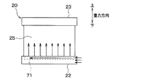
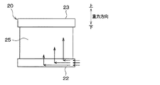
図4、5に、それぞれ、本実施形態、比較例1における第2ヒータコア20内の冷却水流れを示す。比較例1は、本実施形態の加熱用熱交換器2を、その空気流入面が鉛直方向に対して平行となるように、空調ケース51に垂直に設置したものである。また、比較例1では、冷却水入口20aを入口側タンク部22の長手方向に投影したときに、入口側タンク部22の冷却水入口20aの全部がチューブ21の入口側端部21aの真下に位置しており、高温の冷却水が貯液部に貯まるようになっていない。
4 and 5 show the cooling water flow in the
第2ヒータコア20に流入する冷却水が、第1ヒータコア10に流入する冷却水より小流量かつ低流速の場合、図5に示す比較例1では、入口側タンク部22に流入した高温の冷却水の多くが、冷却水入口に近いチューブを流れ、冷却水入口から遠いチューブまで冷却水が流れ難いという現象が生じてしまう。
When the cooling water flowing into the
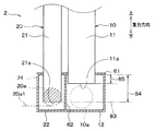
これに対して、本実施形態では、図2に示すように、第2ヒータコア20を傾斜させているので、入口側タンク部22のうちチューブ21の入口側端部21aよりも上方の領域に、複数のチューブ21積層方向全域にわたって、高温の冷却水が貯まる貯液部71が形成される。この貯液部71は、入口側タンク部22が有する角部のうち最も高い位置にある角部に形成されている。
On the other hand, in the present embodiment, as shown in FIG. 2, the
このため、図4に示すように、入口側タンク部22に流入した冷却水であって、出口側タンク部内の冷却水よりも高温の冷却水は、浮力の影響で貯液部71に貯まった後、この貯液部71から複数のチューブのそれぞれに流入する。
For this reason, as shown in FIG. 4, the cooling water that has flowed into the inlet
特に、本実施形態では、図2に示すように、冷却水入口20aを入口側タンク部22の長手方向(図2中の紙面垂直方向)に投影したとき、冷却水入口20aの一部が、チューブ21の入口側端部21aでのチューブ内壁21bから重力方向に平行に引いたチューブ内側延長線(仮想線)81よりも外側に位置している。
In particular, in the present embodiment, as shown in FIG. 2, when the cooling
ここで、冷却水入口20aを入口側タンク部22の長手方向に投影したときに、入口側タンク部22の冷却水入口20aの全部がチューブ21の入口の重力方向での真下に位置すると、入口側タンク部22に流入した高温の冷却水は浮力によって上昇するため、冷却水入口20aから入口側タンク部22に高温の冷却水が流入したとき、流入した冷却水の上方に位置するチューブ21に高温の冷却水が流入してしまう。
Here, when the cooling
これに対して、本実施形態では、冷却水入口20aの一部がチューブ21の入口の真下を除く位置にあるので、冷却水入口20aから流入した高温の冷却水の一部を確実に貯液部71に導くことができる。
On the other hand, in this embodiment, since a part of the cooling
したがって、本実施形態によれば、比較例1と比較して、熱交換コア部25を流れる冷却水の車両左右方向での温度差を低減できる。よって、本実施形態によれば、加熱用熱交換器2を通過後の空調風に生じる車両左右方向での温度差を低減することができる。
Therefore, according to this embodiment, the temperature difference in the vehicle left-right direction of the cooling water flowing through the heat
この結果、加熱用熱交換器2の通過後の空調風が車両左右方向の一方側と他方側に分岐して、運転席側の吹出口、助手席側の吹出口から空調風が吹き出される場合において、車室内の運転席側と助手席側の吹出空気温度差が低減される。
As a result, the conditioned air after passing through the
また、本実施形態によれば、比較例1と比較して、熱交換コア部25での実質的な熱交換面積が増大するので、熱交換コア部25で冷却水から取れる熱量が向上し、熱交換性能が向上する。
Moreover, according to this embodiment, since the substantial heat exchange area in the heat
(第2実施形態)
図6に本実施形態における加熱用熱交換器2の断面図を示す。図6は、図2と同じ方向で見た図である。
(Second Embodiment)
FIG. 6 shows a cross-sectional view of the
本実施形態においても、図6に示すように、第2ヒータコア20が傾斜していることで、入口側タンク部22のうちチューブ21の入口側端部21aよりも上方の領域に、貯液部71が形成されている。
Also in the present embodiment, as shown in FIG. 6, the
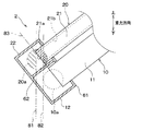
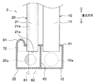
さらに、本実施形態では、第2ヒータコア20の入口側タンク部22における冷却水入口20aとチューブ21との位置関係が次のようになっている。すなわち、図6に示すように、冷却水入口20aを入口側タンク部22の長手方向に投影したとき、冷却水入口20aの一部(図6中の斜線が付されていない領域)がチューブ21の入口側端部(下端面)21aよりも下方に位置している。
Furthermore, in this embodiment, the positional relationship between the cooling
そして、冷却水入口20aの大部分(図6中の斜線領域)が、チューブ21の入口側端部21aでのチューブ内壁21bから重力方向に平行に引いた2本の仮想線81、82の間よりも外側に位置する。ここで、冷却水入口20aの大部分とは、冷却水入口20aの面積の50%以上を占める部分を意味する。また、2本の仮想線81、82の間であって、チューブ21の入口よりも下側の位置がチューブ21の入口の真下の位置である。
And most of the cooling
このように、本実施形態では、冷却水入口20aの全面積の50%以上の大部分が、2本の仮想線81、82の間の領域から外側にはみ出しているので、冷却水入口20aから流入する冷却水の半分以上を貯液部71に導くことができる。
Thus, in this embodiment, since most of 50% or more of the total area of the cooling
(第3実施形態)
図7に本実施形態における加熱用熱交換器2の断面図を示す。図7は、図2と同じ方向で見た図である。
(Third embodiment)
FIG. 7 shows a sectional view of the
本実施形態においても、図7に示すように、第2ヒータコア20が傾斜していることで、第1、第2実施形態と同様に、入口側タンク部22のうちチューブ21の入口側端部21aよりも上方の領域に、図示しない貯液部が形成されている。
Also in the present embodiment, as shown in FIG. 7, the
また、第2ヒータコア20の入口側タンク部22における冷却水入口20aとチューブ21との位置関係が次のようになっている。
The positional relationship between the cooling
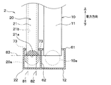
すなわち、図7に示すように、冷却水入口20aを入口側タンク部22の長手方向に投影したとき、冷却水入口20aの一部(図7中の斜線が付されていない領域)がチューブ21の入口側端部(下端面)21aの真下に位置している。そして、冷却水入口20aの他の一部(図7中の斜線領域)がチューブ21の真下を除く位置にある。具体的には、冷却水入口20aの一部(図7中の斜線の向きが左上から右下である斜線領域)が、チューブ21の入口側端部21aでのチューブ内壁21bから重力方向に平行に引いた2本の仮想線81、82の間よりも外側に位置している。さらに、冷却水入口20aの一部(図7中の斜線の向きが右上から左下である斜線領域)が、チューブ21の入口側端部21aを通る仮想線83よりも上側に位置し、冷却水入口20aの一部がチューブ21と重複する位置関係となっている。なお、仮想線83が通る入口側端部21aとは、冷却水入口20aを入口側タンク部22の長手方向に投影したときのチューブ21の入口側端辺のことである。また、仮想線83よりも上側に位置するとは、仮想線83よりもチューブ21の長手方向他端側に位置することを意味する。
That is, as shown in FIG. 7, when the cooling
ちなみに、第1ヒータコア10のように、流入する冷却水が大流量の場合、冷却水入口の一部をチューブの入口側端辺よりも上側に位置させて、冷却水入口の一部がチューブと重複する位置関係とすると、入口側タンク部22を冷却水が流れる際に圧力損失が増大するという問題が生じるため、このような位置関係を採用できない。これに対して、第2ヒータコア20のように、流入する冷却水が小流量の場合であれば、このような圧力損失の増大という問題が生じないので、冷却水入口20aの一部がチューブ21と重複する位置関係の採用が可能である。
Incidentally, as in the case of the
このように、冷却水入口20aの一部を、重力方向に平行な2本の仮想線81、82の間よりも外側に位置させることに加えて、チューブ21の入口側端辺よりも上側に位置させることでも、冷却水入口20aから流入した高温の冷却水の一部を確実に貯液部71に導くことができる。この結果、本実施形態によれば、加熱用熱交換器2を通過後の空調風に生じる車両左右方向での温度差を低減することができる。
Thus, in addition to positioning a part of the cooling
ここで、冷却水入口20aの全面積に対するチューブ21の入口の真下を除く位置にある部分の面積の比(以下、単に面積比と呼ぶ)と、加熱用熱交換器2を通過後の空調風に生じる車両左右方向での温度差低減の効果との関係について説明する。
Here, the ratio of the area of the portion at the position excluding the area directly below the inlet of the
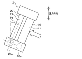
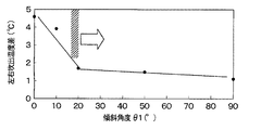
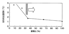
図8は、第2ヒータコア20の傾斜角度θ1を説明するための加熱用熱交換器2の側面図である。図9は、加熱用熱交換器2からの左右吹出空気の温度差と図8に示す傾斜角度θ1との関係を示す評価結果である。図10は、図9中の横軸を傾斜角度θ1から面積比に変更した評価結果である。傾斜角度θ1は、図8に示すように、加熱用熱交換器2を側方から見たときに、チューブ21の長手方向と鉛直方向とのなす角度である。また、加熱用熱交換器2からの左右吹出空気の温度差とは、加熱用熱交換器の左右方向での一方側半分からの吹出空気の平均温度と、他方側半分からの吹出空気の平均温度との差(絶対値)である。
FIG. 8 is a side view of the
ちなみに、図8に示す加熱用熱交換器2では、図3に示す加熱用熱交換器と同様に、左右方向一方側の端部に冷却水入口20aを設けている。また、図8に示す加熱用熱交換器2では、空気流れ方向において、冷却水入口20aの直径がチューブ21の内径と略同等であり、冷却水入口20aの中心とチューブ21の中心とが同じ位置にあり、冷却水入口20aの一部がチューブ21の入口側端辺よりも上側に位置している。
Incidentally, in the
このような加熱用熱交換器2において、傾斜角度θ1が変化すると、面積比も変化する。具体的には、図9中の傾斜角度θ1が0、10、20、50、90度のそれぞれが、図10中の面積比が8、25、35、65、100%に対応している。傾斜角度θ1が0度のとき、冷却水入口20aにおける重力方向に平行な2本の仮想線81、82の間よりも外側に位置する部分(図7中の斜線の向きが左上から右下である斜線領域参照)の面積が最小となる。そして、傾斜角度θ1を増大させると、図7に示されるように、冷却水入口20aは、重力方向に平行な2本の仮想線81、82の間よりも外側に位置する部分の面積が増大する。傾斜角度θ1が90度のとき、チューブ21の入口側端辺が鉛直方向に平行となるため、仮想線81、82が1本に重なり、チューブ21の入口の真下の領域が存在しないので、面積比が100%となる。なお、冷却水入口20aがチューブ21と重複する部分の面積は、傾斜角度θによらず一定である。
In such a
そして、図9、10に示すように、加熱用熱交換器2からの左右吹出空気の温度差は、傾斜角度θ1が増加、すなわち、面積比が増加するにつれて小さくなる傾向がある。特に、傾斜角度θ1が20度以上のとき、すなわち、面積比が35%以上のときの左右吹出空気の温度差は、傾斜角度θ1が90度のとき、すなわち、面積比が100%のときの温度差に近くなっている。このことから、加熱用熱交換器2からの左右吹出空気の温度差を特に小さくするためには、面積比を35%以上とすることが好ましいと言える。
9 and 10, the temperature difference between the left and right blown air from the
また、本実施形態では、冷却水入口20aの一部がチューブ21と重複する位置関係としているので、第2実施形態で説明した図6中の入口側タンク部22と比較してわかるように、入口側タンク部22のチューブ長手方向での寸法を小さくすることができる。
Further, in this embodiment, since a part of the cooling
なお、本実施形態では、冷却水入口20aの一部(図7中の斜線領域)がチューブ21の真下を除く位置にあるように、冷却水入口20aの一部を、重力方向に平行な2本の仮想線81、82の間よりも外側に位置させることと、チューブ21の入口側端辺を通る仮想線83よりも上側に位置させることの両方を採用したが、どちらか一方のみを採用しても良い。これらの場合においても、本実施形態と同様に、面積比を35%以上とすることが好ましい。
In the present embodiment, a part of the cooling
(第4実施形態)
図11に本実施形態における加熱用熱交換器2の断面図を示す。図11は、図2と同じ方向で見た図である。
(Fourth embodiment)
FIG. 11 shows a sectional view of the
本実施形態では、上述の第1〜第3実施形態と異なり、加熱用熱交換器2の車両搭載姿勢を、空気流出入面が鉛直方向に平行な姿勢としている。すなわち、加熱用熱交換器2は、チューブ11、21の長手方向が鉛直方向に平行な向きで、空調ケース内に保持されている。
In the present embodiment, unlike the first to third embodiments described above, the vehicle mounting posture of the
そして、第2ヒータコア20において、入口側タンク部22を構成する壁の一部91が他の部分よりも外側に膨らんでおり、この膨らんだ部分91によって、高温の冷却水が貯まる貯液部72が形成されている。なお、本実施形態の貯液部72も、入口側タンク部22のうちチューブ21の入口側端部21aよりも上方の領域である。
In the
具体的には、入口側タンク部22は、図示しないが、チューブ21が挿入されているコアプレートと、タンク本体部とが結合されており、入口側タンク部22を構成する上側の壁であるコアプレートの一部91が外側に膨らんでいる。
Specifically, although not shown, the inlet
また、本実施形態においても、入口側タンク部22における冷却水入口20aとチューブ21との位置関係が、次のようになっている。
Also in the present embodiment, the positional relationship between the cooling
すなわち、図11に示すように、冷却水入口20aの一部(図11中の斜線が付されていない領域)がチューブ21の入口側端部(下端面)21aよりも下方に位置している。そして、冷却水入口20aの一部(図11中の斜線領域)が、チューブ21の入口側端部21aでのチューブ内壁21bから重力方向に平行に引いた2本の仮想線81、82の間よりも外側に位置している。
That is, as shown in FIG. 11, a part of the cooling
したがって、本実施形態においても、冷却水入口20aの一部がチューブ21の入口の真下を除く位置にあるので、冷却水入口20aから流入した高温の冷却水を確実に貯液部72に導くことができる。そして、この貯液部72から複数のチューブ21のそれぞれに、高温の冷却水を流入させることができるので、熱交換コア部を流れる冷却水の車両左右方向での温度差を低減でき、加熱用熱交換器2を通過後の空調風に生じる車両左右方向での温度差を低減することができる。なお、本実施形態においても、第3実施形態と同様に、面積比を35%以上とすることが好ましい。
Therefore, also in this embodiment, since a part of the cooling
(第5実施形態)
図12に本実施形態における加熱用熱交換器2の断面図を示す。図12は、図2と同じ方向で見た図である。
(Fifth embodiment)
FIG. 12 shows a sectional view of the
本実施形態は、第3実施形態で説明した加熱用熱交換器2の向きを、第4実施形態と同様に、チューブ11、21の長手方向が鉛直方向に平行な向きに変更したものである。ただし、本実施形態では、第2ヒータコア20の入口側タンク部22に、第4実施形態で説明した図11中の膨らんだ部分91は設けられていない。
In this embodiment, the direction of the
具体的には、図12に示すように、本実施形態においても、入口側タンク部22のうちチューブ21の入口側端部21aよりも上方の領域に、貯液部73が形成されている。
Specifically, as shown in FIG. 12, also in this embodiment, a
また、冷却水入口20aを入口側タンク部22の長手方向に投影したとき、冷却水入口20aの一部(図12中の斜線が付されていない領域)がチューブ21の入口側端部(下端面)21aよりも下方に位置している。
In addition, when the cooling
そして、冷却水入口20aの一部(図12中の斜線の向きが左上から右下である斜線領域)が、チューブ21の入口側端部21aでのチューブ内壁21bから重力方向に平行に引いた2本の仮想線81、82の間よりも外側に位置している。さらに、冷却水入口20aの一部(図12中の斜線の向きが右上から左下である斜線領域)が、チューブ21の入口側端辺を通る仮想線83よりも上側に位置している。
A part of the cooling
したがって、本実施形態においても、第3実施形態と同様の効果を奏する。なお、本実施形態においても、第3実施形態と同様に、面積比を35%以上とすることが好ましい。 Therefore, also in this embodiment, there exists an effect similar to 3rd Embodiment. In the present embodiment, it is preferable that the area ratio is 35% or more, as in the third embodiment.
また、貯液部73の容積を確保するという観点では、後述する第6実施形態のように、一般的な熱交換器と比較して、第2ヒータコア20の入口側タンク部22内に挿入されているチューブ21の挿入長さを長くすることが好ましい。
Further, from the viewpoint of securing the volume of the
(第6実施形態)
図13に本実施形態における加熱用熱交換器2の断面図を示す。図13は、図2と同じ方向で見た図である。
(Sixth embodiment)
FIG. 13 shows a sectional view of the
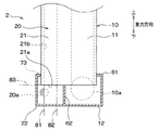
図13に示すように、本実施形態の加熱用熱交換器2も、第4、5実施形態と同様に、チューブ11、21の長手方向が鉛直方向に平行な向きで、空調ケース内に保持されている。
As shown in FIG. 13, the
そして、第2ヒータコア20の入口側タンク部22内に挿入されているチューブ21の挿入長さ84が、第1ヒータコア10の入口側タンク部12内に挿入されているチューブ11の挿入長さ85よりも長くなっている。この挿入長さ84、85とは、入口側タンク部22、12の内壁からチューブ21、11の入口側端部21a、11aまでの長さである。これにより、入口側タンク部22のうちチューブ21の入口側端部21aよりも上方の領域に形成される貯液部74の容積を大きくしている。
The
また、本実施形態では、第2ヒータコア20の入口側タンク部22における冷却水入口20aとチューブ21との位置関係において、冷却水入口20aの大部分(図13中の斜線領域)が、水平方向に平行に引いたチューブの入口側端部(入口側端辺)21aを通る仮想線83よりも上側に位置する関係となっている。ここで、冷却水入口20aの大部分は、第3実施形態での説明と同様に、面積比が35%以上であることが好ましい。
Further, in the present embodiment, in the positional relationship between the cooling
なお、本実施形態のように、第2ヒータコア20の入口側タンク部22に挿入されているチューブ21の挿入長さ84が長い場合、冷却水入口20aの下端の位置20a1がチューブ21の入口側端部21aと同位置もしくはそれよりも上方に位置するようにすることが最も好ましい。すなわち、冷却水入口20aの面積の100%がチューブ21と重複する位置関係とすることが最も好ましい。これにより、冷却水入口20aから流入した高温の冷却水の全部を貯液部74に導くことができる。
In addition, when the
(第7実施形態)
図14に、本実施形態における加熱用熱交換器の正面図を示す。本実施形態は、第5実施形態で説明した図12に示す加熱用熱交換器2の車両搭載姿勢を、空気流出入面が鉛直方向に平行であることに加えて、入口側タンク部22が冷却水入口10aから奥にかけて重力方向上方に傾斜するように変更したものである。その他の構成については、第5実施形態と同様である。
(Seventh embodiment)
In FIG. 14, the front view of the heat exchanger for a heating in this embodiment is shown. In the present embodiment, the vehicle mounting posture of the
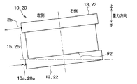
具体的には、図14に示すように、第2ヒータコア20の入口側タンク部22は、入口側タンク部22の長手方向(左右方向)の一方側端部に冷却水入口20aを有し、入口側タンク部22の長手方向の一方側端部から冷却水が流入するようになっている。そして、第2ヒータコア20を正面から見たとき、第2ヒータコア20は、入口側タンク部22の上壁が、入口側タンク部22の長手方向一端側よりも長手方向他端側が重力方向上方に位置するように、傾斜した状態である。このとき、第2ヒータコア20は、第2ヒータコア20の入口側タンク部22の上壁と水平方向とのなす角度を傾斜角度θ2として、所定の傾斜角度θ2を有している。
Specifically, as shown in FIG. 14, the inlet
ここで、入口側タンク部22の上壁とは、入口側タンク部22が、チューブ21が挿入されるコアプレートと、タンク部を構成するタンク本体部とを有する構成の場合、コアプレートのことである。また、所定の傾斜角度θ2は、空調ケースの樹脂成型時に空調ケースの加熱用熱交換器の保持部に設けられる型抜きのための標準的な型抜き勾配である1〜1.5度と同じであっても良いが、それを超える大きさ、例えば、3度以上とすることが好ましい。第2ヒータコア20は、このように傾斜した状態で、空調ケース51内に保持されて、車両に搭載されている。
Here, the upper wall of the inlet
このように、冷却水入口20aよりも奥が上に位置するように、入口側タンク部22の上壁を傾斜させることで、入口側タンク部22の上壁が水平の場合と比較して、貯液部を流れる高温の冷却水を上壁に伝わらせて、入口側タンク部22の冷却水入口20aから離れた奥側により導きやすくすることができる。この結果、本実施形態によれば、入口側タンク部22の上壁が水平である第5実施形態よりも、加熱用熱交換器2を通過後の空調風に生じる車両左右方向での温度差を低減することができる。
In this way, by inclining the upper wall of the inlet
ここで、図15に、傾斜角度θ2と左右吹出空気温度差との関係についての評価結果を示す。図15からわかるように、傾斜角度θ2が0〜12度の範囲では、傾斜角度θ2が大きくなるにつれて左右吹出空気温度差は低下する傾向があるが、傾斜角度θ2が12度を超える範囲では、傾斜角度θ2が大きくなるにつれて左右吹出空気温度差が増大する傾向がある。そこで、傾斜角度θ2の上限としては、傾斜角度θ2が3度のときと左右吹出空気温度差(絶対値)が同じである19.5度とすることが好ましい。 Here, in FIG. 15, the evaluation result about the relationship between inclination-angle (theta) 2 and right and left blowing air temperature difference is shown. As can be seen from FIG. 15, when the inclination angle θ2 is in the range of 0 to 12 degrees, the left and right blown air temperature difference tends to decrease as the inclination angle θ2 increases, but in the range where the inclination angle θ2 exceeds 12 degrees, As the inclination angle θ2 increases, the left and right blown air temperature difference tends to increase. Therefore, the upper limit of the tilt angle θ2 is preferably 19.5 degrees, which is the same as the left and right blown air temperature difference (absolute value) when the tilt angle θ2 is 3 degrees.
なお、本実施形態では、加熱用熱交換器2の全体を傾けることで、第2ヒータコア20の入口側タンク部22の上壁と水平方向とのなす角度を所定の傾斜角度θ2としたが、加熱用熱交換器2の全体を傾ける代わりに、第2ヒータコア20の入口側タンク部22の形状を、入口側タンク部22の上壁が傾斜した形状としても良い。
In the present embodiment, by tilting the
また、本実施形態は、第5実施形態に限らず、空気流出入面を垂直方向に平行とする第4、第6実施形態にも適用可能であり、空気流出入面を傾斜させる第1〜第3実施形態にも適用可能である。 Further, the present embodiment is not limited to the fifth embodiment, and can be applied to the fourth and sixth embodiments in which the air inflow / outflow surface is parallel to the vertical direction. The present invention can also be applied to the third embodiment.
(第8実施形態)
上述の各実施形態は、入口側タンク部22の内部に高温の冷却水が貯まる貯液部を形成したものであったが、本実施形態は、入口側タンク部22の冷却水入口側における冷却水の流速を上昇させるものである。
(Eighth embodiment)
In each of the above-described embodiments, a liquid storage part in which high-temperature cooling water is stored is formed inside the inlet-
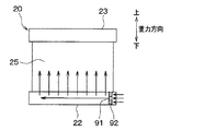
図16に、本実施形態における第2ヒータコア20の正面図を示す。図16に示すように、本実施形態では、入口側タンク部22の内部の冷却水入口側に、入口側タンク部22に流入した冷却水の流速を上昇させる流速上昇手段として、入口側タンク部22よりも流路断面積が小さな流通穴91を有する板状部材92を設けている。
FIG. 16 shows a front view of the
流通穴91の寸法については、例えば、入口側タンク部22の内部の直径が16mmである場合、流通穴91の直径を5mm以下とする。このように、流通穴91の直径を入口側タンク部22の直径の約1/3以下とする。
About the dimension of the
これにより、本実施形態によれば、流通穴91通過後の冷却水の流速を、流通穴91通過前の冷却水の流速よりも上昇させることができる。
Thereby, according to this embodiment, the flow rate of the cooling water after passing through the
ここで、第1実施形態で説明した通り、第2ヒータコア20に流入する冷却水が小流量の場合、入口側タンク部22を流れる冷却水の流速が低いと、冷却水入口から遠いチューブまで冷却水が流れ難いという現象が生じてしまう。
Here, as described in the first embodiment, when the cooling water flowing into the
これに対して、本実施形態によれば、入口側タンク部22に流入した冷却水の流速を上昇させることができるので、冷却水の流速を上昇させる手段を設けていない場合と比較して、入口側タンク部22の奥まで冷却水を流すことができる。
On the other hand, according to the present embodiment, since the flow rate of the cooling water flowing into the inlet
よって、本実施形態においても、熱交換コア部25を流れる冷却水の車両左右方向での温度差を低減でき、加熱用熱交換器2を通過後の空調風に生じる車両左右方向での温度差を低減することができる。
Therefore, also in this embodiment, the temperature difference in the vehicle left-right direction of the cooling water flowing through the heat
なお、本実施形態では、第1〜第7実施形態で説明した貯液部を形成していないが、第1〜第7実施形態と同様に、貯液部を形成しても良い。すなわち、本実施形態を、第1〜第7実施形態と組み合わせても良く、組み合わせることで、より高い効果が得られる。 In addition, in this embodiment, although the liquid storage part demonstrated in 1st-7th embodiment is not formed, you may form a liquid storage part similarly to 1st-7th embodiment. That is, this embodiment may be combined with the first to seventh embodiments, and a higher effect can be obtained by combining.
(第9実施形態)
図17に本実施形態における加熱用熱交換器2の断面図を示す。図17は、図2と同じ方向で見た図である。本実施形態では、第5実施形態で説明した図12に示す加熱用熱交換器2に対して、第2ヒータコア20の冷却水入口20aの開口面積および図示しない冷却水導入路の流路断面積を、第1ヒータコア10のそれよりも小さくすることで、第2ヒータコア20の入口側タンク部22を流れる冷却水の流速を高めている。ここで、冷却水導入路とは、入口側タンク部22に冷却水を導くために、冷却水入口20aに連なっている配管のことである。
(Ninth embodiment)
FIG. 17 shows a cross-sectional view of the
このため、本実施形態によれば、第2ヒータコア20の冷却水入口20aの開口面積および図示しない冷却水導入路の流路断面積が、第1ヒータコア10のそれと同等である場合と比較して、入口側タンク部22の奥まで冷却水を流すことができる。
For this reason, according to this embodiment, compared with the case where the opening area of the cooling
また、本実施形態では、第2ヒータコア20の入口側タンク部22の流路断面積が、第1ヒータコア10の入口側タンク部12の流路断面積よりも小さくなっている。これによっても、第2ヒータコア20の入口側タンク部22の流路断面積が、第1ヒータコア10の入口側タンク部12の流路断面積と同等である場合と比較して、第2ヒータコア20の入口側タンク部22を流れる冷却水の流速を高めることができ、入口側タンク部22の奥まで冷却水を流すことができる。
In the present embodiment, the flow path cross-sectional area of the inlet
本実施形態においては、第1ヒータコア10の入口側タンク部12を流れる冷却水の流速と同等以上となるように、第2ヒータコア20の入口側タンク部22を流れる冷却水の流速を高めることが好ましい。
In the present embodiment, the flow rate of the cooling water flowing through the inlet
なお、本実施形態では、第2ヒータコア20の冷却水入口20aの開口面積および図示しない冷却水導入路の流路断面積と、第2ヒータコア20の入口側タンク部22の流路断面積の両方を小さくしていたが、これらの一方のみによって、第2ヒータコア20の入口側タンク部22を流れる冷却水の流速を高めても良い。また、このように、第2ヒータコア20の入口側タンク部22を流れる冷却水の流速を高める構成については、第5実施形態に限らず、それ以外の各実施形態で説明した加熱用熱交換器に適用可能である。
In the present embodiment, both the opening area of the cooling
また、本実施形態においても、冷却水入口20aの一部(図17中の斜線領域)が、チューブ21の入口側端部21aでのチューブ内壁21bから重力方向に平行に引いた2本の仮想線81、82の間よりも外側に位置している。このため、冷却水入口20aから流入した高温の冷却水の一部を貯液部73に導くことができる。
Also in this embodiment, a part of the cooling
なお、本実施形態においては、第2ヒータコア20の入口側タンク部22を流れる冷却水の流速を高めることで、入口側タンク部22の奥まで冷却水を流すことができるので、冷却水入口20aの全部がチューブ21の入口の真下に位置していても良い。
In the present embodiment, the cooling water can flow to the depth of the inlet
また、本実施形態では、第1ヒータコア10と第2ヒータコア20のタンク部を一体化することに加えて、第1ヒータコア10と第2ヒータコア20のチューブ11、21を一体化することにより、第1ヒータコア10と第2ヒータコア20とを一体化している。ちなみに、第1ヒータコア10と第2ヒータコア20のチューブ11、21同士が連なっているが、チューブ11、21内部の流路は、第1ヒータコア10と第2ヒータコア20で別々に形成されている。このとき、第1ヒータコア10と第2ヒータコア20のフィン同士を別体としても、一体としても良い。
In the present embodiment, in addition to integrating the tank portions of the
(第10実施形態)
図18(a)に本実施形態における加熱用熱交換器2の側面図を示し、図18(b)に図18(a)中の第2ヒータコア20の正面図を示す。
(10th Embodiment)
FIG. 18A shows a side view of the
本実施形態は、加熱用熱交換器2の構造は第1実施形態と同じであるが、加熱用熱交換器2の上下が第1実施形態と異なっている。すなわち、第1、第2ヒータコア10、20の入口側タンク部12、22は、上側に位置しており、第1、第2ヒータコア10、20の出口側タンク部13、23は、下側に位置している。そして、加熱用熱交換器2は、チューブ11、21の長手方向が鉛直方向に平行な向きで、空調ケース内に保持されている。
In this embodiment, the structure of the
このため、本実施形態では、第2ヒータコア20の入口側タンク部22に冷却水が流入したとき、図18(b)に示すように、出口側タンク部23内の冷却水よりも高温の冷却水は、浮力の影響で入口側タンク部22内の上方の領域75に、複数のチューブ21の積層方向全域にわたって貯まった後、この上方の領域75から複数のチューブのそれぞれに流入する。そして、高温の冷却水が複数のチューブ21を上から下に向かって流れる。このように、本実施形態では、入口側タンク部22内の上方の領域75が貯液部となる。
For this reason, in this embodiment, when cooling water flows into the inlet
よって、本実施形態によれば、熱交換コア部25を流れる冷却水の車両左右方向での温度差を低減でき、加熱用熱交換器2を通過後の空調風に生じる車両左右方向での温度差を低減することができる。
Therefore, according to this embodiment, the temperature difference in the vehicle left-right direction of the cooling water flowing through the heat
(第11実施形態)
図19に本実施形態における加熱用熱交換器2の側面図を示す。本実施形態は、第10実施形態で説明した図18に示す加熱用熱交換器2に対して、第1ヒータコア10の上下を入れ替えたものである。
(Eleventh embodiment)
FIG. 19 shows a side view of the
具体的には、図19に示すように、第1ヒータコア10と第2ヒータコア20とは、入口側、出口側それぞれのタンク部が一体化されることで、両者が一体化した構造となっている。
Specifically, as shown in FIG. 19, the
そして、加熱用熱交換器2の上側に位置する上側タンク部61の内部が仕切壁62によって、第1ヒータコア10の出口側タンク部13と、第2ヒータコア20の入口側タンク部22とに区画されている。
The inside of the
同様に、加熱用熱交換器2の下側に位置する下側タンク部63の内部が仕切壁64によって、第1ヒータコア10の入口側タンク部12と、第2ヒータコア20の出口側タンク部23とに区画されている。
Similarly, the inside of the
第1ヒータコア10では、下側に位置する入口側タンク部12に設けられた冷却水入口10aから流入した冷却水が、チューブ11を下から上に向かって流れ、上側に位置する出口側タンク部13に設けられた冷却水出口10bから流出するようになっている。
In the
一方、第2ヒータコア20では、上側に位置する入口側タンク部22に設けられた冷却水入口20aから流入した冷却水が、チューブ21を上から下に向かって流れ、下側に位置する出口側タンク部23に設けられた冷却水出口20bから流出するようになっている。
On the other hand, in the
本実施形態においても、第2ヒータコア20の入口側タンク部22が上側に位置するので、第8実施形態と同様の効果が得られる。
Also in this embodiment, since the inlet
さらに、本実施形態によれば、第1ヒータコア10内の冷却水流れ方向が、第2ヒータコア20内の冷却水流れ方向と反対であるので、加熱用熱交換器2を通過後の空気の上下温度分布、すなわち、上側と下側での温度差を低減することができる。
Furthermore, according to the present embodiment, the flow direction of the cooling water in the
(他の実施形態)
(1)上述の各実施形態では、第2ヒータコア20の入口側タンク部22に設けられた冷却水入口20aは、入口側タンク部22を構成する壁に形成された開口部であったが、この開口部に管が挿入されて、入口側タンク部22の内壁よりも入口側タンク部22の内側に管が突出した状態としても良い。この場合、入口側タンク部22の内側に突出した管の先端部が、入口側タンク部22内に面するとともに、入口側タンク部22に冷却水を導入する冷却水導入路の末端開口部である。
(Other embodiments)
(1) In each of the above-described embodiments, the cooling
(2)上述の第1〜7、9〜11実施形態では、第2ヒータコア20の冷却水入口20aが、入口側タンク部22の車両左右方向での一端側に配置されていたが、一端側だけでなく両端側に配置されていたり、中央に配置されていたりしても良い。このような配置であっても、本発明によれば、冷却水入口20aから離れた位置にあるチューブ21に高温の冷却水を流すことができる。
(2) In the above-described first to seventh and ninth to eleventh embodiments, the cooling
(3)上述の各実施形態では、第1ヒータコア10と第2ヒータコア20とを一体化していたが、第1ヒータコア10と第2ヒータコア20とを別体としても良い。
(3) In each of the above-described embodiments, the
さらに、上述の各実施形態では、第1ヒータコア10内の冷却水流れの向きが、第2ヒータコア20と同じ下から上の向きであったが、第2ヒータコア20とは逆の上から下の向きであっても良い。
Further, in each of the above-described embodiments, the direction of the cooling water flow in the
(4)上述の各実施形態では、エンジン30の第1冷却水出口31bから流出の冷却水は、シリンダヘッド31を冷却した冷却水のみであったが、シリンダヘッド31を冷却した冷却水に対してシリンダブロック32を冷却した冷却水の一部が混入した冷却水でも良い。要するに、エンジン30の第1冷却水出口31bから主にシリンダヘッド31を冷却した冷却水が流出するようになっていれば良い。
(4) In each of the above-described embodiments, the cooling water flowing out from the first
同様に、エンジン30の第2冷却水出口32bから流出の冷却水は、シリンダブロック32を冷却した冷却水のみであったが、シリンダブロック32を冷却した冷却水に対してシリンダヘッド31を冷却した冷却水の一部が混入した冷却水でも良い。要するに、エンジン30の第2冷却水出口32bから主にシリンダブロック32を冷却した冷却水が流出し、第1冷却水出口31bから流出の冷却水よりも第2冷却水出口32bから流出の冷却水の方が高温になっていれば良い。
Similarly, the cooling water flowing out from the second
ただし、エンジン30の第2冷却水出口32bから流出の冷却水については、シリンダヘッド31を冷却した後の冷却水とシリンダブロック32を冷却した後の冷却水とを全部混合した場合よりも高温とする。これにより、両方の冷却水を全部混合した場合と比較して、高温の冷却水をエンジン30から流出させることができるからである。
However, the cooling water flowing out from the second
(5)上述の各実施形態では、第2ヒータコア20に流入する冷却水は、エンジン30の第2冷却水出口32bから流出の冷却水のみであったが、第1冷却水出口31bから流出の冷却水の一部が混入しても良い。
(5) In each of the above-described embodiments, the cooling water flowing into the
要するに、主に第2冷却水出口32bから流出の冷却水であって、第1ヒータコア10に流入する冷却水よりも高温の冷却水が第2ヒータコア20に流入するようになっていれば良い。ただし、第2ヒータコア20に流入する冷却水は、第2冷却水出口32bから流出の冷却水と第1冷却水出口31bから流出の冷却水とを全部混合したときの平均温度よりも高温とする。これにより、両方の冷却水を全部混合した場合と比較して、第2ヒータコア20で加熱後の空気温度を高くできるからである。
In short, it is only necessary that the cooling water mainly flows out from the second
(6)上述の各実施形態では、第1ヒータコア10がシリンダヘッド冷却後の冷却水を熱源とし、第2ヒータコア20がシリンダブロック冷却後の冷却水を熱源としていたが、第1ヒータコア10および第2ヒータコア20は、他の液体を熱源としても良い。第1ヒータコア10が第1液体を熱源とし、第2ヒータコア20が第1液体よりも高温かつ小流量の第2液体を熱源としている場合に、本発明の適用が可能である。
(6) In each of the embodiments described above, the
例えば、ハイブリッド車両に搭載される車両用空調装置においては、第1液体としてインバータ等の電気機器の冷却液を用い、第2液体としてエンジンの冷却液を用いることができる。また、例えば、電気自動車に搭載される車両用空調装置においては、第1液体としてインバータ等の電気機器の冷却液を用い、第2液体として電気ヒータ等の加熱手段によって加熱した高温液体を用いることができる。このように、本発明の車両用空調装置は、ハイブリッド車両以外の車両にも適用可能である。 For example, in a vehicle air conditioner mounted on a hybrid vehicle, the coolant of an electric device such as an inverter can be used as the first liquid, and the engine coolant can be used as the second liquid. Further, for example, in a vehicle air conditioner mounted on an electric vehicle, a cooling liquid of an electric device such as an inverter is used as the first liquid, and a high-temperature liquid heated by heating means such as an electric heater is used as the second liquid. Can do. Thus, the vehicle air conditioner of the present invention can be applied to vehicles other than hybrid vehicles.
(7)上述の各実施形態を実施可能な範囲で組み合わせても良い。 (7) You may combine each above-mentioned embodiment in the range which can be implemented.
1 車両用空調装置
2 加熱用熱交換器
10 第1ヒータコア(第1熱交換部)
20 第2ヒータコア(第2熱交換部)
21 チューブ
22 入口側タンク部
23 出口側タンク部
51 空調ケース
71 貯液部
72 貯液部
73 貯液部
74 貯液部
DESCRIPTION OF
20 2nd heater core (2nd heat exchange part)
21
Claims (13)
前記加熱用熱交換器(2)は、前記第1液体と前記送風空気とを熱交換させる第1熱交換部(10)と、前記第2液体と前記第1熱交換部(10)で加熱された前記送風空気とを熱交換させる第2熱交換部(20)とを備え、
前記第2熱交換部(20)は、積層された複数のチューブ(21)と、前記複数のチューブ(21)の長手方向一端側に連通し、液体入口側となる入口側タンク部(22)と、前記複数のチューブ(21)の長手方向他端側に連通し、液体出口側となる出口側タンク部(23)とを備え、
前記第2熱交換部(20)は、前記入口側タンク部(22)が重力方向下側に位置し、前記出口側タンク部(23)が重力方向上側に位置するように、空調ケース(51)内に保持されており、
前記第2熱交換部(20)は、前記入口側タンク部(22)に流入した第2液体であって、前記出口側タンク部(23)内の液体よりも高温の液体が、前記複数のチューブ(21)の積層方向全域にわたる前記入口側タンク部内の貯液部(71、72、73、74)に貯まった後、前記複数のチューブ(21)に流入する構成となっていることを特徴とする車両用空調装置。 A heat exchanger (2) for heating that heats the air blown into the vehicle interior using the first liquid and the second liquid having a higher temperature and a lower flow rate than the first liquid as a heat source,
The heating heat exchanger (2) is heated by the first heat exchange unit (10) for exchanging heat between the first liquid and the blown air, and the second liquid and the first heat exchange unit (10). A second heat exchange section (20) for exchanging heat with the blown air,
The second heat exchange section (20) communicates with a plurality of stacked tubes (21) and one end side in the longitudinal direction of the plurality of tubes (21), and forms an inlet side tank section (22) serving as a liquid inlet side. And an outlet side tank portion (23) that communicates with the other end side in the longitudinal direction of the plurality of tubes (21) and serves as a liquid outlet side,
The second heat exchange part (20) includes an air conditioning case (51) such that the inlet side tank part (22) is located on the lower side in the gravitational direction and the outlet side tank part (23) is located on the upper side in the gravitational direction. )
The second heat exchange part (20) is a second liquid that has flowed into the inlet side tank part (22), and a liquid having a higher temperature than the liquid in the outlet side tank part (23) After being stored in the liquid storage part (71, 72, 73, 74) in the inlet side tank part over the entire stacking direction of the tube (21), it is configured to flow into the plurality of tubes (21). A vehicle air conditioner.
前記貯液部(71)は、前記第2熱交換部(20)が傾斜することで、前記入口側タンク部(22)内のうち、前記チューブ(21)の入口側端部(21a)よりも上方の領域に形成されていることを特徴とする請求項1に記載の車両用空調装置。 The second heat exchange part (20) is inclined so that an angle formed between the longitudinal direction of the tube (21) and the vertical direction becomes an acute angle when the second heat exchange part (20) is viewed from the side. In this state, it is held in the air conditioning case (51) and mounted on the vehicle,
The liquid storage part (71) is inclined from the inlet side end part (21a) of the tube (21) in the inlet side tank part (22) by the inclination of the second heat exchange part (20). The vehicle air conditioner according to claim 1, wherein the vehicle air conditioner is also formed in an upper region.
前記第2熱交換部(20)の前記入口側タンク部(22)内に挿入されている前記チューブ(21)の挿入長さ(84)が、前記第1熱交換部(10)の前記入口側タンク部(12)内に挿入されている前記チューブ(11)の挿入長さ(85)よりも長くなっており、
前記貯液部(74)は、前記第2熱交換部(10)の前記入口側タンク部(22)内のうち、前記チューブ(21)の入口側端部(21a)よりも重力方向上方の領域に形成されていることを特徴とする請求項1ないし3のいずれか1つに記載の車両用空調装置。 The first heat exchange section (10) communicates with a plurality of stacked tubes (11) and one end side in the longitudinal direction of the plurality of tubes (11), and forms an inlet side tank section (12) serving as a liquid inlet side. And an outlet side tank portion (13) that communicates with the other end side in the longitudinal direction of the plurality of tubes (11) and is a liquid outlet side,
The insertion length (84) of the tube (21) inserted into the inlet side tank part (22) of the second heat exchange part (20) is the inlet of the first heat exchange part (10). It is longer than the insertion length (85) of the tube (11) inserted in the side tank part (12),
The liquid storage part (74) is located above the inlet side end part (21a) of the tube (21) in the gravity direction in the inlet side tank part (22) of the second heat exchange part (10). The vehicle air conditioner according to any one of claims 1 to 3, wherein the vehicle air conditioner is formed in a region.
前記液体導入路の末端開口部(20a)の少なくとも一部が、前記チューブ(21)の入口の重力方向での真下を除く位置にあることを特徴とする請求項1ないし4のいずれか1つに記載の車両用空調装置。 A terminal opening (20a) of the liquid introduction path for introducing the second liquid into the inlet side tank part (22) of the second heat exchange part (20) is projected in the longitudinal direction of the inlet side tank part (22). When
The at least one part of the terminal opening part (20a) of the said liquid introduction path exists in the position except the right under the gravity direction of the inlet_port | entrance of the said tube (21), The one of Claim 1 thru | or 4 characterized by the above-mentioned. The vehicle air conditioner described in 1.
前記第2熱交換部(20)の入口側タンク部(22)の流路断面積が、前記第1熱交換部(10)の入口側タンク部(12)の流路断面積よりも小さいことを特徴とする請求項1ないし10のいずれか1つに記載の車両用空調装置。 The first heat exchange section (10) communicates with a plurality of stacked tubes (11) and one end side in the longitudinal direction of the plurality of tubes (11), and forms an inlet side tank section (12) serving as a liquid inlet side. And an outlet side tank part (13) that communicates with the other end side in the longitudinal direction of the plurality of tubes (11) and that becomes the liquid outlet side,
The flow path cross-sectional area of the inlet side tank part (22) of the second heat exchange part (20) is smaller than the flow path cross sectional area of the inlet side tank part (12) of the first heat exchange part (10). The vehicle air conditioner according to any one of claims 1 to 10.
前記第2熱交換部(20)の前記入口側タンク部(22)に前記第2液体を導入する液体導入路の流路断面積が、前記第1熱交換部(10)の入口側タンク部(12)に前記第1液体を導入する液体導入路の流路断面積よりも小さいことを特徴とする請求項1ないし11のいずれか1つに記載の車両用空調装置。 The first heat exchange section (10) communicates with a plurality of stacked tubes (11) and one end side in the longitudinal direction of the plurality of tubes (11), and forms an inlet side tank section (12) serving as a liquid inlet side. And an outlet side tank part (13) that communicates with the other end side in the longitudinal direction of the plurality of tubes (11) and that becomes the liquid outlet side,
The cross-sectional area of the liquid introduction path for introducing the second liquid into the inlet side tank part (22) of the second heat exchange part (20) is the inlet side tank part of the first heat exchange part (10). The vehicle air conditioner according to any one of claims 1 to 11, wherein the vehicle air conditioner is smaller than a flow path cross-sectional area of a liquid introduction path for introducing the first liquid into (12).
前記加熱用熱交換器(2)は、前記第1液体と前記送風空気とを熱交換させる第1熱交換部(10)と、前記第2液体と前記第1熱交換部(10)で加熱された前記送風空気とを熱交換させる第2熱交換部(20)とを備え、
前記第2熱交換部(20)は、積層された複数のチューブ(21)と、前記複数のチューブ(21)の長手方向一端側に連通し、液体入口側となる入口側タンク部(22)と、前記複数のチューブ(21)の長手方向他端側に連通し、液体出口側となる出口側タンク部(23)とを備え、
前記第2熱交換部(20)は、前記入口側タンク部(22)が重力方向下側に位置し、前記出口側タンク部(23)が重力方向上側に位置するように、空調ケース(51)内に保持されており、
前記入口側タンク部(22)の内部に、前記入口側タンク部(22)に流入した第2液体の流速を上昇させる流速上昇手段(92)を設けたことを特徴とする車両用空調装置。 A heat exchanger (2) for heating that heats the air blown into the vehicle interior using the first liquid and the second liquid having a higher temperature and a lower flow rate than the first liquid as a heat source,
The heating heat exchanger (2) is heated by the first heat exchange unit (10) for exchanging heat between the first liquid and the blown air, and the second liquid and the first heat exchange unit (10). A second heat exchange section (20) for exchanging heat with the blown air,
The second heat exchange section (20) communicates with a plurality of stacked tubes (21) and one end side in the longitudinal direction of the plurality of tubes (21), and forms an inlet side tank section (22) serving as a liquid inlet side. And an outlet side tank portion (23) that communicates with the other end side in the longitudinal direction of the plurality of tubes (21) and serves as a liquid outlet side,
The second heat exchange part (20) includes an air conditioning case (51) such that the inlet side tank part (22) is located on the lower side in the gravitational direction and the outlet side tank part (23) is located on the upper side in the gravitational direction. )
A vehicle air conditioner characterized in that a flow velocity increasing means (92) for increasing the flow velocity of the second liquid flowing into the inlet side tank portion (22) is provided inside the inlet side tank portion (22).
Priority Applications (3)
| Application Number | Priority Date | Filing Date | Title |
|---|---|---|---|
| JP2011006181A JP5533685B2 (en) | 2011-01-14 | 2011-01-14 | Air conditioner for vehicles |
| DE102012200229A DE102012200229A1 (en) | 2011-01-14 | 2012-01-10 | Vehicle air conditioning system |
| US13/348,918 US20120180989A1 (en) | 2011-01-14 | 2012-01-12 | Vehicular air-conditioning system |
Applications Claiming Priority (1)
| Application Number | Priority Date | Filing Date | Title |
|---|---|---|---|
| JP2011006181A JP5533685B2 (en) | 2011-01-14 | 2011-01-14 | Air conditioner for vehicles |
Publications (2)
| Publication Number | Publication Date |
|---|---|
| JP2012144222A true JP2012144222A (en) | 2012-08-02 |
| JP5533685B2 JP5533685B2 (en) | 2014-06-25 |
Family
ID=46489882
Family Applications (1)
| Application Number | Title | Priority Date | Filing Date |
|---|---|---|---|
| JP2011006181A Expired - Fee Related JP5533685B2 (en) | 2011-01-14 | 2011-01-14 | Air conditioner for vehicles |
Country Status (3)
| Country | Link |
|---|---|
| US (1) | US20120180989A1 (en) |
| JP (1) | JP5533685B2 (en) |
| DE (1) | DE102012200229A1 (en) |
Cited By (2)
| Publication number | Priority date | Publication date | Assignee | Title |
|---|---|---|---|---|
| KR101664744B1 (en) * | 2015-09-24 | 2016-10-12 | 현대자동차주식회사 | Air conditioner for vehicle |
| CN106482541A (en) * | 2015-08-31 | 2017-03-08 | 中瑞新源能源科技(天津)股份有限公司 | A kind of flue gas heat recovery device of long service life |
Families Citing this family (4)
| Publication number | Priority date | Publication date | Assignee | Title |
|---|---|---|---|---|
| EP2392794B1 (en) * | 2010-06-07 | 2019-02-27 | Ford Global Technologies, LLC | Separately cooled turbo charger for maintaining a no-flow strategy of a cylinder block coolant lining |
| WO2014059993A1 (en) * | 2012-10-16 | 2014-04-24 | Dantherm Air Handling A/S | Heat exchanger |
| TWI677659B (en) * | 2019-01-16 | 2019-11-21 | 萬在工業股份有限公司 | Parallel condensation device |
| US12560384B2 (en) * | 2022-07-27 | 2026-02-24 | Blue Frontier Inc. | Plate-fin heat exchanger |
Citations (11)
| Publication number | Priority date | Publication date | Assignee | Title |
|---|---|---|---|---|
| JPS6018413A (en) * | 1983-07-12 | 1985-01-30 | Toyota Motor Corp | Car room heater |
| JPH03287409A (en) * | 1990-04-04 | 1991-12-18 | Nippondenso Co Ltd | Automotive air conditioner |
| JPH06229697A (en) * | 1993-02-05 | 1994-08-19 | Zexel Corp | Heat exchanger |
| JPH07149135A (en) * | 1993-11-30 | 1995-06-13 | Nippondenso Co Ltd | Air conditioner for vehicle |
| JPH1148760A (en) * | 1997-06-05 | 1999-02-23 | Denso Corp | Hot water heating system |
| JP2001026210A (en) * | 1999-07-14 | 2001-01-30 | Denso Corp | Vehicle air conditioner |
| JP2001304775A (en) * | 2000-04-26 | 2001-10-31 | Mitsubishi Heavy Ind Ltd | Air conditioner for vehicle |
| JP2002130866A (en) * | 2000-10-24 | 2002-05-09 | Showa Denko Kk | Condenser for air conditioning |
| JP2004177041A (en) * | 2002-11-28 | 2004-06-24 | Matsushita Electric Ind Co Ltd | Heat exchanger |
| JP2005059808A (en) * | 2003-08-20 | 2005-03-10 | Denso Corp | Air conditioner for vehicles |
| JP2005082079A (en) * | 2003-09-10 | 2005-03-31 | Denso Corp | Air conditioner and vehicle air conditioner |
Family Cites Families (5)
| Publication number | Priority date | Publication date | Assignee | Title |
|---|---|---|---|---|
| JPS60113017A (en) * | 1983-11-25 | 1985-06-19 | Toyota Motor Corp | Operation control method for cooling fan of 2-system cooling type internal-combustion engine |
| US4535729A (en) * | 1984-10-05 | 1985-08-20 | Deere & Company | Vehicle cooling system utilizing one radiator |
| US5337704A (en) | 1993-09-29 | 1994-08-16 | Chrysler Corporation | Engine cooling system with thermostat coolant flow control between head and block |
| BR9701062A (en) * | 1997-02-24 | 1998-11-10 | Gen Motors Brasil Ltda | Independent cooling system for alternative internal combustion engines |
| DE59808921D1 (en) | 1998-12-07 | 2003-08-07 | Ford Global Tech Inc | Cooling and heating circuit and heat exchanger for motor vehicles with additional coolant heating device |
-
2011
- 2011-01-14 JP JP2011006181A patent/JP5533685B2/en not_active Expired - Fee Related
-
2012
- 2012-01-10 DE DE102012200229A patent/DE102012200229A1/en not_active Ceased
- 2012-01-12 US US13/348,918 patent/US20120180989A1/en not_active Abandoned
Patent Citations (11)
| Publication number | Priority date | Publication date | Assignee | Title |
|---|---|---|---|---|
| JPS6018413A (en) * | 1983-07-12 | 1985-01-30 | Toyota Motor Corp | Car room heater |
| JPH03287409A (en) * | 1990-04-04 | 1991-12-18 | Nippondenso Co Ltd | Automotive air conditioner |
| JPH06229697A (en) * | 1993-02-05 | 1994-08-19 | Zexel Corp | Heat exchanger |
| JPH07149135A (en) * | 1993-11-30 | 1995-06-13 | Nippondenso Co Ltd | Air conditioner for vehicle |
| JPH1148760A (en) * | 1997-06-05 | 1999-02-23 | Denso Corp | Hot water heating system |
| JP2001026210A (en) * | 1999-07-14 | 2001-01-30 | Denso Corp | Vehicle air conditioner |
| JP2001304775A (en) * | 2000-04-26 | 2001-10-31 | Mitsubishi Heavy Ind Ltd | Air conditioner for vehicle |
| JP2002130866A (en) * | 2000-10-24 | 2002-05-09 | Showa Denko Kk | Condenser for air conditioning |
| JP2004177041A (en) * | 2002-11-28 | 2004-06-24 | Matsushita Electric Ind Co Ltd | Heat exchanger |
| JP2005059808A (en) * | 2003-08-20 | 2005-03-10 | Denso Corp | Air conditioner for vehicles |
| JP2005082079A (en) * | 2003-09-10 | 2005-03-31 | Denso Corp | Air conditioner and vehicle air conditioner |
Cited By (2)
| Publication number | Priority date | Publication date | Assignee | Title |
|---|---|---|---|---|
| CN106482541A (en) * | 2015-08-31 | 2017-03-08 | 中瑞新源能源科技(天津)股份有限公司 | A kind of flue gas heat recovery device of long service life |
| KR101664744B1 (en) * | 2015-09-24 | 2016-10-12 | 현대자동차주식회사 | Air conditioner for vehicle |
Also Published As
| Publication number | Publication date |
|---|---|
| JP5533685B2 (en) | 2014-06-25 |
| US20120180989A1 (en) | 2012-07-19 |
| DE102012200229A1 (en) | 2012-08-09 |
Similar Documents
| Publication | Publication Date | Title |
|---|---|---|
| JP4970022B2 (en) | Combined heat exchanger and combined heat exchanger system | |
| JP5533685B2 (en) | Air conditioner for vehicles | |
| CN103459968B (en) | Heat exchanger | |
| JP5184314B2 (en) | Cooling system | |
| JP2010127508A (en) | Combined heat exchanger | |
| KR101405234B1 (en) | Radiator for vehicle | |
| US10508865B2 (en) | Heat exchanger | |
| US20160138871A1 (en) | Duplex heat exchanger | |
| US9618282B2 (en) | Radiator for vehicle | |
| JP2008080995A (en) | Cooling system | |
| US20200224580A1 (en) | Heat exchanger | |
| JP6296439B2 (en) | Vehicle radiator | |
| KR20150017401A (en) | Radiator for vehicle | |
| JP5609635B2 (en) | Air conditioner for vehicles | |
| KR20130020100A (en) | Cooling system for vehicle | |
| JP2012145311A (en) | Vehicle air conditioning device | |
| JP2018105535A (en) | Intercooler | |
| JP6460281B2 (en) | Intercooler | |
| JP5640875B2 (en) | Combined heat exchanger | |
| KR102609386B1 (en) | Heat exchanger and air conditioner for vehicle | |
| JP5531991B2 (en) | Air conditioner for vehicles | |
| KR101724751B1 (en) | Radiator for stack with double pipe of air conditioner in fuel cell vehicle | |
| JP2007186047A (en) | Vehicular heat exchanger | |
| JP2015128923A (en) | Vehicle cooling system | |
| JP2011183868A (en) | Air conditioner for vehicle |
Legal Events
| Date | Code | Title | Description |
|---|---|---|---|
| A621 | Written request for application examination |
Free format text: JAPANESE INTERMEDIATE CODE: A621 Effective date: 20130221 |
|
| A977 | Report on retrieval |
Free format text: JAPANESE INTERMEDIATE CODE: A971007 Effective date: 20131213 |
|
| A131 | Notification of reasons for refusal |
Free format text: JAPANESE INTERMEDIATE CODE: A131 Effective date: 20140114 |
|
| A521 | Request for written amendment filed |
Free format text: JAPANESE INTERMEDIATE CODE: A523 Effective date: 20140311 |
|
| TRDD | Decision of grant or rejection written | ||
| A01 | Written decision to grant a patent or to grant a registration (utility model) |
Free format text: JAPANESE INTERMEDIATE CODE: A01 Effective date: 20140401 |
|
| R151 | Written notification of patent or utility model registration |
Ref document number: 5533685 Country of ref document: JP Free format text: JAPANESE INTERMEDIATE CODE: R151 |
|
| A61 | First payment of annual fees (during grant procedure) |
Free format text: JAPANESE INTERMEDIATE CODE: A61 Effective date: 20140414 |
|
| R250 | Receipt of annual fees |
Free format text: JAPANESE INTERMEDIATE CODE: R250 |
|
| R250 | Receipt of annual fees |
Free format text: JAPANESE INTERMEDIATE CODE: R250 |
|
| R250 | Receipt of annual fees |
Free format text: JAPANESE INTERMEDIATE CODE: R250 |
|
| R250 | Receipt of annual fees |
Free format text: JAPANESE INTERMEDIATE CODE: R250 |
|
| R250 | Receipt of annual fees |
Free format text: JAPANESE INTERMEDIATE CODE: R250 |
|
| LAPS | Cancellation because of no payment of annual fees |