JP2012144229A - Tire - Google Patents
Tire Download PDFInfo
- Publication number
- JP2012144229A JP2012144229A JP2011006299A JP2011006299A JP2012144229A JP 2012144229 A JP2012144229 A JP 2012144229A JP 2011006299 A JP2011006299 A JP 2011006299A JP 2011006299 A JP2011006299 A JP 2011006299A JP 2012144229 A JP2012144229 A JP 2012144229A
- Authority
- JP
- Japan
- Prior art keywords
- tire
- rail
- width direction
- land portion
- circumferential
- Prior art date
- Legal status (The legal status is an assumption and is not a legal conclusion. Google has not performed a legal analysis and makes no representation as to the accuracy of the status listed.)
- Granted
Links
- 238000005299 abrasion Methods 0.000 abstract 1
- 230000002093 peripheral effect Effects 0.000 abstract 1
- 230000000452 restraining effect Effects 0.000 abstract 1
- 230000000052 comparative effect Effects 0.000 description 12
- 230000000694 effects Effects 0.000 description 12
- 238000012360 testing method Methods 0.000 description 12
- 230000001133 acceleration Effects 0.000 description 5
- 238000011161 development Methods 0.000 description 3
- 238000011156 evaluation Methods 0.000 description 3
- 150000001875 compounds Chemical class 0.000 description 2
- 201000004384 Alopecia Diseases 0.000 description 1
- 229910000831 Steel Inorganic materials 0.000 description 1
- 238000010835 comparative analysis Methods 0.000 description 1
- 230000000881 depressing effect Effects 0.000 description 1
- 230000009977 dual effect Effects 0.000 description 1
- 230000002708 enhancing effect Effects 0.000 description 1
- 230000003676 hair loss Effects 0.000 description 1
- 208000014674 injury Diseases 0.000 description 1
- 238000011835 investigation Methods 0.000 description 1
- 239000000463 material Substances 0.000 description 1
- 239000002184 metal Substances 0.000 description 1
- 230000008520 organization Effects 0.000 description 1
- 238000011056 performance test Methods 0.000 description 1
- 238000007634 remodeling Methods 0.000 description 1
- 239000010959 steel Substances 0.000 description 1
- 230000008733 trauma Effects 0.000 description 1
- XLYOFNOQVPJJNP-UHFFFAOYSA-N water Substances O XLYOFNOQVPJJNP-UHFFFAOYSA-N 0.000 description 1
Images


Landscapes
- Tires In General (AREA)
Abstract
Description
本発明は、道路上の走行および軌道のレール上の走行の両方に使用されるタイヤに関する。本発明は特に、道路上における氷雪上性能をさほど犠牲にすることなく、トレッド部のレール当接領域がレール非当接領域に比べて早く摩耗する不均一摩耗を抑制することが可能なタイヤに関する。 The present invention relates to a tire used for both traveling on a road and traveling on a rail of a track. In particular, the present invention relates to a tire capable of suppressing uneven wear in which the rail contact region of the tread wears faster than the rail non-contact region without sacrificing performance on snow and snow on the road. .
近年、道路上および軌道上の両方を走行可能な車両(DMV:Dual Mode Vehicle)が提案されている。路上輸送は、道路さえあればどの目的地にも輸送可能という利点がある。一方、鉄道輸送は、渋滞の影響を受けにくく、予定通りの輸送が可能という利点がある。そのため、この両用走行車両(以下「DMV」ともいう。)は、路上輸送および鉄道輸送の両方の利点を享受でき、特に廃線となった軌道を有効活用できることが期待されている。 In recent years, a vehicle (DMV: Dual Mode Vehicle) capable of traveling on both roads and tracks has been proposed. Road transportation has the advantage that it can be transported to any destination as long as there is a road. On the other hand, rail transport has the advantage that it is less susceptible to traffic jams and can be transported as planned. For this reason, this dual-purpose traveling vehicle (hereinafter also referred to as “DMV”) is expected to be able to enjoy the advantages of both road transport and rail transport, and in particular, to effectively utilize the track that has been abolished.
DMVに装着されるタイヤ(以下「DMV用タイヤ」ともいう。)のトレッド部は、道路走行時には路面と接触してDMVに駆動力を与え、軌道走行時にはレールと接触してDMVに駆動力を与えるものである。そのため、DMV用タイヤのトレッド部は、両方の走行に適した特性を有することが必要とされ、道路のみを走行する通常の車両用のタイヤとは異なる特性が求められるものと考えられる。 A tread portion of a tire attached to the DMV (hereinafter also referred to as “DMV tire”) is in contact with the road surface when driving on the road to apply driving force to the DMV, and is contacted with the rail when traveling on track to apply driving force to the DMV. Give. Therefore, the tread portion of the DMV tire is required to have characteristics suitable for both travels, and it is considered that characteristics different from those for a normal vehicle tire traveling only on a road are required.
特許文献1には、道路上の走行と軌道のレール上の走行の両方に使用されるタイヤとして、トレッド部が複数本の周方向溝と幅方向溝とにより区画形成されるブロック基調のトレッドパターンが開示されている。この文献では、複数本の周方向溝のうち、レールとの当接領域の両外側に形成される2本の周方向溝を、他の周方向溝よりも幅広に形成している。 In Patent Document 1, as a tire used for both traveling on a road and traveling on a rail of a track, a tread pattern based on a block in which a tread portion is formed by a plurality of circumferential grooves and width grooves is formed. Is disclosed. In this document, of the plurality of circumferential grooves, two circumferential grooves formed on both outer sides of the contact area with the rail are formed wider than the other circumferential grooves.
DMVでは、冬季に氷雪上走行の安全を確保する必要がある。このため、特許文献1のタイヤにおいても、トレッド部全体をブロック基調のトレッドパターンとして、氷雪上性能を確保している。 In DMV, it is necessary to ensure the safety of running on ice and snow in winter. For this reason, also in the tire of patent document 1, the whole tread part is made into the tread pattern of a block fundamental tone, and the performance on ice and snow is ensured.
一方、タイヤはトレッド部がレールの頂面よりも幅広で、トレッド部の幅方向における一部でしかレールの頂面と接触しないのが一般的である。そのため、軌道走行時には、トレッド部のうちレールとの当接領域にのみDMVの全荷重がかかり、レールとの非当接領域には荷重がかからない状態で、タイヤが負荷転動することになる。これが、レール当接領域での大きな摩耗原因となっている。その結果、レール当接領域がレール非当接領域に比べて早く摩耗する不均一摩耗が生じる。すると、トレッド部のレール非当接領域では摩耗が進行していないにも関わらず、レール当接領域で摩耗が進行してしまう結果、タイヤの使用寿命が短くなってしまう。 On the other hand, the tire generally has a tread portion wider than the top surface of the rail, and only a part of the tread portion in the width direction contacts the top surface of the rail. For this reason, during track running, the entire load of DMV is applied only to the contact area with the rail in the tread portion, and the tire rolls in a state where no load is applied to the non-contact area with the rail. This is a major cause of wear in the rail contact area. As a result, non-uniform wear occurs in which the rail contact area wears faster than the rail non-contact area. Then, although wear does not progress in the rail non-contact area of the tread portion, wear progresses in the rail contact area, resulting in a shortened service life of the tire.
氷雪上性能を確保するために、トレッド部全体をブロック基調のトレッドパターンとしたタイヤでは、トレッド部の剛性が低くなっているため、この傾向が顕著である。各ブロックにサイプを設けている場合には、なおさらである。 In order to ensure the performance on snow and snow, in a tire in which the entire tread portion has a block-based tread pattern, since the rigidity of the tread portion is low, this tendency is remarkable. This is especially true when sipes are provided in each block.
特許文献1では、複数本の周方向溝のうち、レールとの当接領域の両外側に形成される2本の周方向溝を、他の周方向溝よりも幅広に形成することで、レール当接領域に存在するブロックが幅広の周方向溝に逃げられるようにして、レールとの圧接状態を緩和している。しかしながら、このタイヤでは、レール当接領域を含むトレッド部全体がブロック基調であるため、レールと接触するブロックの剛性が低くなっていることに変わりはない。そのため、依然としてトレッド部のレール当接領域がレール非当接領域に比べて早く摩耗する不均一摩耗を十分に抑制することはできない。 In Patent Document 1, a rail is formed by forming two circumferential grooves formed on both outer sides of a contact area with the rail out of a plurality of circumferential grooves so as to be wider than other circumferential grooves. The pressure contact state with the rail is eased by allowing the block existing in the contact area to escape into the wide circumferential groove. However, in this tire, since the entire tread portion including the rail contact region has a block tone, the rigidity of the block in contact with the rail remains low. Therefore, it is still impossible to sufficiently suppress uneven wear in which the rail contact area of the tread portion wears faster than the rail non-contact area.
そこで本発明は、上記課題に鑑み、道路上の走行および軌道のレール上の走行の両方に使用されるタイヤであって、道路上における氷雪上性能をさほど犠牲にすることなく、トレッド部のレール当接領域がレール非当接領域に比べて早く摩耗する不均一摩耗を十分に抑制することが可能なタイヤを提供することを目的とする。 Therefore, in view of the above problems, the present invention is a tire that is used for both traveling on a road and traveling on a rail of a track, and the rail of the tread portion without sacrificing the performance on ice and snow on the road. It is an object of the present invention to provide a tire capable of sufficiently suppressing non-uniform wear in which the contact region wears faster than the rail non-contact region.
上記課題を解決すべく本発明者が鋭意検討したところ、レール当接領域がブロックパターンである以上、レール当接領域での剛性の低下は避けられず、不均一摩耗を抑制することができないことが判明した。その結果、本発明者は、DMV用タイヤとして、レール当接領域と非当接領域とで、トレッドパターン基調を変更することによって道路走行時と軌道走行時との機能分離を図るという、これまでにない着想を得た。 As a result of extensive studies by the inventor in order to solve the above-mentioned problems, as long as the rail contact area is a block pattern, a decrease in rigidity in the rail contact area is inevitable and uneven wear cannot be suppressed. There was found. As a result, as a DMV tire, the present inventor has attempted to separate functions between road running and track running by changing the tread pattern keynote between the rail contact area and the non-contact area. I got a new idea.
この着想に基づき、本発明者は、レール当接領域での剛性を確保するべく、トレッド部のうち当該領域では、ブロックではなくリブ状陸部を基調としたトレッドパターンとし、残りの部分では従来通りブロック基調のトレッドパターンとすることとした。レール当接領域をリブ状陸部とした結果、レール当接領域がブロック基調の従来パターンに比べて道路上における氷雪上性能については低下することが考えられる。しかしながら、本発明者がさらに検討したところ、当該構成によれば、道路上における氷雪上性能をさほど犠牲にすることなく、不均一摩耗を有効に抑制できることを見出し、本発明を完成するに至った。 Based on this idea, in order to ensure the rigidity in the rail contact area, the present inventor made a tread pattern based on a rib-like land portion instead of a block in the tread portion, and in the remaining portion, the conventional portion The tread pattern was based on street blocks. As a result of the rail contact area being a rib-like land portion, it is conceivable that the performance on ice and snow on the road is reduced compared to the conventional pattern in which the rail contact area is block-based. However, as a result of further investigation by the present inventors, it was found that according to the configuration, uneven wear can be effectively suppressed without sacrificing the performance on the snow and ice on the road, and the present invention has been completed. .
すなわち、上記課題に鑑み、本発明の要旨構成は以下の通りである。
(1)道路上の走行および軌道のレール上の走行の両方に使用されるタイヤであって、
トレッド部に、
タイヤ周方向に沿って延びる少なくとも2本の周方向溝を配置して、リブ状陸部を区画形成し、
前記周方向溝のうち、タイヤ赤道面を挟んで最もタイヤ幅方向外側に位置する2本の最外周方向溝のタイヤ幅方向外側に、少なくともタイヤ幅方向に沿って延びる複数本の幅方向溝をタイヤ周方向に間隔をおいて配置して、複数個のブロック陸部からなるブロック陸部群を区画形成し、
前記リブ状陸部は、前記トレッド部のレール当接領域全体にわたって少なくとも位置し、
前記ブロック陸部群は、前記トレッド部のレール非当接領域に位置することを特徴とするタイヤ。
That is, in view of the above problems, the gist of the present invention is as follows.
(1) A tire used for both traveling on a road and traveling on a rail of a track,
In the tread part,
Disposing at least two circumferential grooves extending along the tire circumferential direction to define a rib-like land portion;
Among the circumferential grooves, a plurality of widthwise grooves extending at least along the tire width direction are provided on the outer sides in the tire width direction of the two outermost circumferential grooves positioned on the outermost side in the tire width direction across the tire equatorial plane. Arranging the block land portion group consisting of a plurality of block land portions at intervals in the tire circumferential direction,
The rib-like land portion is located at least over the entire rail contact region of the tread portion,
The tire is characterized in that the block land portion group is located in a rail non-contact region of the tread portion.
(2)前記リブ状陸部は、タイヤ幅方向に延び、両端が前記リブ状陸部内で終端する複数本の第1幅方向サイプを有する上記(1)に記載のタイヤ。 (2) The tire according to (1), wherein the rib-shaped land portion has a plurality of first width-direction sipes extending in the tire width direction and having both ends terminating in the rib-shaped land portion.
(3)前記ブロック陸部は、該ブロック陸部をタイヤ幅方向に完全に横切る第2幅方向サイプを有する上記(1)または(2)に記載のタイヤ。 (3) The tire according to (1) or (2), wherein the block land portion has a second width direction sipe that completely crosses the block land portion in the tire width direction.
(4)前記トレッド部は、点対称のトレッドパターンを有する上記(1)乃至(3)のいずれか1項に記載のタイヤ。 (4) The tire according to any one of (1) to (3), wherein the tread portion has a point-symmetric tread pattern.
(5)前記タイヤは冬用タイヤである上記(1)乃至(4)のいずれか1項に記載のタイヤ。 (5) The tire according to any one of (1) to (4), wherein the tire is a winter tire.
(6)前記タイヤは重荷重用タイヤである上記(1)乃至(5)のいずれか1項に記載のタイヤ。 (6) The tire according to any one of (1) to (5), wherein the tire is a heavy duty tire.
本発明によれば、トレッド部をリブ状陸部とその両側のブロック陸部群とに区分けし、リブ状陸部がレール当接領域全体にわたって位置することにより、レール当接領域での剛性が高まり、不均一摩耗を抑制することができる一方、ブロック陸部群がレール非当接領域に位置することにより、道路上における氷雪上性能を確保することができる。 According to the present invention, the tread portion is divided into the rib-like land portion and the block land portion groups on both sides thereof, and the rib-like land portion is located over the entire rail contact region, whereby the rigidity in the rail contact region is increased. While it is possible to suppress the uneven wear, the block land portion group is located in the rail non-contact region, so that the performance on ice and snow on the road can be ensured.
以下、図面を参照しつつ本発明をより詳細に説明する。なお、同一の構成要素には原則として同一の参照番号を付し、説明は省略する。 Hereinafter, the present invention will be described in more detail with reference to the drawings. In principle, the same components are denoted by the same reference numerals, and description thereof is omitted.
(DMV)
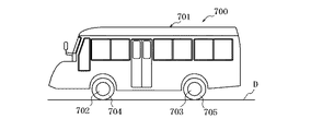
本発明のタイヤを説明する前に、本発明のタイヤが装着される車両であるDMVの一例について、図9〜図11を用いて簡単に説明する。図9および図10は、本発明のタイヤが装着された車両(DMV)700の側面図である。DMV700は、道路上および軌道上の両方を走行可能に構成されている。図9は、DMV700が道路の路面D上を走行している状態を示しており、これを「道路走行状態」という。図10は、DMV700が軌道のレールR上を走行している状態を示しており、これを「軌道走行状態」という。
(DMV)
Before describing the tire of the present invention, an example of a DMV that is a vehicle to which the tire of the present invention is mounted will be briefly described with reference to FIGS. 9 and 10 are side views of a vehicle (DMV) 700 on which the tire of the present invention is mounted. The
DMV700は、車体701、前輪702、後輪703、前方案内輪706、後方案内輪707を有する。前輪702のホイールリムには、前輪タイヤ704が装着されている。後輪703は、道路走行時の荷重を支えるべく複輪となっており、ホイールリムに後輪内側タイヤ100(本発明タイヤ)と後輪外側タイヤ705が装着されている。後輪703は、エンジンにより駆動される駆動輪であり、前輪702は従動輪である。前方案内輪706および後方案内輪707は、一般的に用いられている鉄道車両用車輪と同様の構造であり、鋼等の金属からなる。
The
図9の道路走行状態では、前方案内輪706および後方案内輪707は使用されず、車体701の内部に収容されている。道路走行状態では、DMV700は、エンジンの駆動力が後輪703から路面Dに伝達されることにより走行する。
In the road running state of FIG. 9, the
一方、図10の軌道走行状態では、前方案内輪706および後方案内輪707が使用される。前方案内輪706および後方案内輪707は、一般的な鉄道と同様に、レールRに当接する。この結果、DMV700は脱線することなくレールRの上を走行することができる。すなわち、前方案内輪706および後方案内輪707は、DMV700をレールR上でガイドする役割を果たす。
On the other hand, in the track running state of FIG. 10, the
後輪703は、軌道走行状態においてもレールRと当接しており、DMV700は、エンジンの駆動力が後輪703、より厳密には後輪の内側タイヤ100からレールRに伝達されることにより走行する。一方、前輪702はレールRから上方に離れた状態となっており、レールRとは当接していない。
The
このように後輪703を道路走行状態と軌道走行状態の両方で駆動輪として使用することで、DMV700を簡易に駆動することができる。ここで、軌道走行状態において、前方案内輪706の上下方向位置は、前輪702がレールRから離れるような位置とされる。一方、軌道走行状態において、後方案内輪707の位置は、後輪703および後方案内輪707がレールRと当接するように設定される。このように、道路走行状態から軌道走行状態へ移行するときは、車体701の内部に収容されている前方案内輪706および後方案内輪707を下方に移動させてレールRと当接させ、逆に、軌道走行状態から道路走行状態へ移行するときは、上方に移動させて車体701に収容する。前方案内輪706および後方案内輪707の上下移動は、油圧式アクチュエータなどにより行えばよい。
Thus, the
軌道走行状態において、DMV700の後方荷重は、後輪703と後方案内輪707とで分担して支持される。後輪703が荷重を分担することにより、後輪703に装着されたタイヤとレールRとの間に摩擦力が発生しうる。この摩擦力により駆動力が得られる。後方案内輪707が荷重を分担することにより、DMV701の脱線が防止される。
In the track running state, the rear load of the
図11においては、レールRが二点鎖線で示されている。また図11において、車軸の一部を除き、車両下部の構成は省略されている。軌道走行状態において、後輪703の後輪内側タイヤ100がレールRと当接している。まっすぐな軌道を走行している場合、タイヤ100は、タイヤ幅方向略中心位置においてレールRと当接している。左右のタイヤ100の中心間距離Tcは、レールRの中央間距離Rcと略同一である。軌道における2本のレールの間隔は、一般に軌間(ゲージ)と称される。例えば日本において、軌間には、標準軌、狭軌、広軌等がある。日本においては、新幹線や一部の私鉄等で標準軌が採用され、それら以外の多くの路線では狭軌が採用されている。レールRと当接するタイヤ100の中心間距離Tcは、DMV700が走行する軌道の軌間に基づいて設計される。既存の軌道の軌間に基づいてタイヤの中心間距離Tcを設定すれば、DMV700は既存の軌道を走行することができる。
In FIG. 11, the rail R is indicated by a two-dot chain line. In FIG. 11, the configuration of the lower part of the vehicle is omitted except for a part of the axle. In the track running state, the rear wheel
DMV700に装着されたタイヤのうち、レールRと当接しないタイヤ704,705には、従来の自動車用タイヤを用いることができる。一方、レールRと当接するタイヤ100は、本発明のタイヤを用いる。
Of the tires mounted on the
(実施形態1)
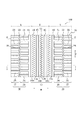
以下、本発明の実施形態1にかかるタイヤ100について、図1および図2を用いて説明する。タイヤ100は、道路上の走行および軌道のレール上の走行の両方に使用されるタイヤであり、DMV700の駆動輪として使用されるものである。タイヤ100は、リブ状陸部13とそのタイヤ幅方向両外側に区画形成されたブロック陸部群20とからなる。
(Embodiment 1)
Hereinafter, a
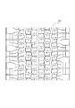
本発明に従うタイヤは、トレッド部に、タイヤ周方向に沿って延びる少なくとも2本の周方向溝を配置して、リブ状陸部を区画形成する。本実施形態のタイヤ100は、トレッド部10に、タイヤ周方向Cに沿って延びる4本の周方向溝11,12,15,16を配置して、3つのリブ状陸部13a,13b,13cを区画形成する。
In the tire according to the present invention, at least two circumferential grooves extending along the tire circumferential direction are arranged in the tread portion to form a rib-like land portion. In the
そして、周方向溝11,12,15,16のうち、タイヤ赤道面CLを挟んで最もタイヤ幅方向外側に位置する2本の最外周方向溝11,12のタイヤ幅方向外側に、複数個のブロック陸部24,25からなるブロック陸部群20を区画形成する。本実施形態では、最外周方向溝11,12のタイヤ幅方向両外側に、それぞれ1本の周方向細溝23を配置する。そして、両端が最外周方向溝11,12と周方向細溝23とに開口し、タイヤ幅方向Wに沿って延びる複数本の第1幅方向溝21をタイヤ周方向Cに間隔をおいて配置する。また、両端がトレッド端Eと周方向細溝23とに開口し、タイヤ幅方向Wに沿って延びる複数本の第2幅方向溝22をタイヤ周方向Cに間隔をおいて配置する。このようにして、最外周方向溝11,12と周方向細溝23と第1幅方向溝21とにより、複数の第1ブロック陸部24からなる第1ブロック陸部列26を区画形成する。同様に、トレッド端Eと周方向細溝23と第2幅方向溝22とにより、複数の第2ブロック陸部25からなる第2ブロック陸部列27を区画形成する。
Of the
本発明の特徴的構成は、リブ状陸部13が、トレッド部10のレール当接領域T全体にわたって少なくとも位置し、ブロック陸部群20がトレッド部10のレール非当接領域Nに位置する構成である。タイヤ100は、トレッド幅がレールRの頂面の幅よりも大きいことが一般的であり、トレッド部10の一定の範囲でのみレールRと接することとなる。
The characteristic configuration of the present invention is such that the rib-
ここで、本明細書において「レール当接領域」とは、トレッド部のうち、タイヤが軌道上を走行するときにレールRと接触しうる領域を意味し、例えば図2に示すように、タイヤのトレッド部においてレール頂面の幅中心位置を中心として、レール幅Wrの100%以内の領域として、特定することができる。この場合は、当接領域Tの幅がレール幅Wrと等しい幅を有する。また、トレッド部におけるレールのタイヤ幅方向端部の両外側であっても、車両旋回など通常の軌道走行においてレールRと接触する頻度が高い領域として、例えば、タイヤのトレッド部においてレール頂面の幅中心位置を中心として、レール幅の150%以内の領域として特定してもよい。なお、タイヤ赤道がレール頂面の幅中心と一致するように当接する場合には、レール当接領域は、タイヤ赤道を中心として、レール幅の100%または150%以内の領域として特定することができる。また、用いるレールのレール幅およびタイヤサイズにも依るが、通常、タイヤ当接領域は、タイヤ赤道を中心としてトレッド幅の55%以下の領域となる。なお、タイヤが空気入りタイヤの場合には、タイヤを適用リムに装着し所定空気圧を充填した後、所定負荷条件におけるタイヤの状態を基準として、レール当接領域を設定する。 Here, the “rail contact area” in the present specification means an area of the tread portion that can contact the rail R when the tire travels on the track. For example, as shown in FIG. In the tread portion, it can be specified as a region within 100% of the rail width Wr, centering on the width center position of the rail top surface. In this case, the width of the contact region T is equal to the rail width Wr. Further, even on both outer sides of the tire width direction end portion of the rail in the tread portion, as a region having a high frequency of contact with the rail R in normal track traveling such as vehicle turning, for example, the rail top surface in the tread portion of the tire You may specify as an area | region within 150% of rail width centering on a width center position. When the tire equator abuts so that it coincides with the center of the width of the rail top surface, the rail abutment region may be specified as a region within 100% or 150% of the rail width centering on the tire equator. it can. Further, although depending on the rail width of the rail to be used and the tire size, the tire contact area is usually an area of 55% or less of the tread width centering on the tire equator. In the case where the tire is a pneumatic tire, the rail contact region is set based on the state of the tire under a predetermined load condition after the tire is mounted on the applicable rim and filled with a predetermined air pressure.
本明細書において「所定空気圧」とは、下記規格に記載されている適用サイズにおける複輪の最大荷重(最大負荷能力)に対応する空気圧のことを意味する。また「所定負荷条件」とは、同規格に記載されている適用サイズにおける複輪の最大荷重(最大負荷能力)の荷重をかけることを意味する。「適用リム」とは、同規格に記載されている適用サイズにおける標準リム(または“Approved Rim”、“Recommended Rim”)のことである。かかる産業規格については、タイヤが生産又は使用される地域に有効な規格が定められている。例えば、アメリカ合衆国では、”The Tire and Rim Association Inc.のYear Book”であり、欧州では、”The European Tire and Rim Technical OrganizationのSTANDARDS MANUAL”であり、日本では日本自動車タイヤ協会の”JATMA Year Book”である。 In the present specification, the “predetermined air pressure” means an air pressure corresponding to the maximum load (maximum load capacity) of a compound wheel in an applicable size described in the following standard. Further, the “predetermined load condition” means that a load of the maximum load (maximum load capacity) of the compound wheel in the application size described in the standard is applied. The “applied rim” is a standard rim (or “Approved Rim” or “Recommended Rim”) in the applicable size described in the standard. As for such industrial standards, standards that are effective in regions where tires are produced or used are defined. For example, “Year Book of The Tire and Rim Association Inc.” in the United States, “STANDARDS MANUAL of The European Tire and Rim Technical Organization” in Europe, and “JATMA Year Book” of the Japan Automobile Tire Association in Japan. It is.
本明細書において「レール非当接領域」とは、トレッド部のうちレール当接領域以外の領域を意味する。 In this specification, the “rail non-contact area” means an area other than the rail contact area in the tread portion.
本発明の上記特徴的構成を採用することによる作用効果を説明する。リブ状陸部13は、トレッド部10のレール当接領域T全体にわたって少なくとも位置する。すなわち、レール当接領域Tでは、トレッド部10に両端が周方向溝に開口する幅方向溝(ラグ溝)や幅方向サイプ(オープンサイプ)が存在せず、リブ状の陸部を形成している。このため、ブロック状陸部に比べて、レール当接領域においてトレッド部の剛性を高めることができる。その結果、軌道走行によるレール当接領域における摩耗を十分に抑制することができ、レール当接領域がレール非当接領域に比べて早く摩耗する不均一摩耗を抑制することができる。一方、ブロック陸部群20はトレッド部10のレール非当接領域Nに位置することとする。これにより、道路走行状態では、トレッド部10のレール非当接領域Nにおいて、幅方向溝21,22によるエッジ効果を得ることができ、道路上における氷雪上性能を確保することができる。
The effect by employ | adopting the said characteristic structure of this invention is demonstrated. The rib-
図1に示すように、リブ状陸部13はレール当接領域T全体にわたって少なくとも位置していればよく、レール非当接領域に一部含まれても構わない。この場合、レール当接領域Tからはみ出すリブ状陸部13のタイヤ幅方向寸法は、トレッド幅の30%以下であることが好ましい。30%超えであると、不均一摩耗を抑制する効果は変わらないものの、道路上での氷雪上性能を確保しにくくなるためである。上記観点から、レール当接領域Tからはみ出すリブ状陸部13のタイヤ幅方向寸法は、トレッド幅の10%以下であることがより好ましい。そして、不均一摩耗を抑制しつつ、道路上における氷雪上性能を最大限確保するためには、リブ状陸部13の両端(図1においては、リブ状陸部13aの左端とリブ状陸部13cの右端)が、レール当接領域Tの両端と等しくなることが最も好ましい。
As shown in FIG. 1, the rib-
なお、レール当接領域は、タイヤ100を装着するDMV700が走行するレールRの寸法、レールの中央間距離Rc、およびタイヤ100の中心間距離Tcにより特定することができる。タイヤ間中心とレール間中心は一致するため、RcとTcが等しい場合には、タイヤ赤道CLがレールR頂面の幅中心と一致するように当接する。しかし、既存の車両を部分的に改造してDMV700を製造する場合や、既存の軌道を利用してDMV700を走行させる場合など、必ずしもRcとTcを一致させることができず、図1に示すように、タイヤ赤道が多少タイヤ幅方向にオフセットして、レールRと当接する場合もある。いずれにしても、レール当接領域を予め特定することができる場合は、この情報に基づいてリブ状陸部13とブロック陸部群20の配置を決定すればよい。また、タイヤ100のリブ状陸部13に包含されるようにレール当接領域を設定してもよい。
The rail contact region can be specified by the dimension of the rail R on which the
タイヤ100が走行可能なレールRの種類は限定されない。レールRの種類として、例えば、30kgレール、37kgレール、40kgレール、50kgNレール、50kgTレール、60kgレール等が存在する。30kgレールのレール幅Wrは60.33mmであり、37kgレールのレール幅Wrは62.71mmであり、40kgレールのレール幅Wrは64mmであり、50kgNレールおよび50kgTレールのレール幅Wrは65mmであり、60kgレールのレール幅Wrは65mmである。一般的な鉄道において、レール幅Wrは、通常、60mm以上65mm以下の範囲である。
The type of rail R on which the
本実施形態のタイヤ100は、トレッド部10に、最外周方向溝11,12以外に2本の周方向溝15,16、すなわち計4本の周方向溝を配設している。リブ状陸部13は、道路走行状態では路面と接触し、軌道走行状態ではレールと当接しうる領域である。そのため、このように3本以上の周方向溝を配置すると、道路走行時および軌道走行時の排水性能を向上させることができるので好ましい。なお、5本を超えてリブ状陸部13に周方向溝を配設すると、リブ状陸部13の剛性を確保し難くなり、トレッド部のレール当接領域がレール非当接領域に比べて早く摩耗する不均一摩耗を抑制する効果が十分に得られなくなるため、周方向溝は5本以内とすることが好ましい。
In the
周方向溝11,12,15,16の形状は、排水性の観点およびリブ状陸部13の剛性の観点から、本実施形態のようにタイヤ周方向に沿って直線状であることが好ましいが、本発明の周方向溝はこれに限定されない。例えば、所定の波長をもつ波状やジグザグ状であってもよい。また、3本以上の周方向溝を配設する場合には、リブ状陸部13の剛性バランスを保つため、これら周方向溝のタイヤ幅方向間隔を等しくすることが好ましい。これら周方向溝の溝幅および溝深さは、リブ状陸部13の剛性バランスを保つため、互いに等しくすることが好ましい。
The shape of the
リブ状陸部13は、タイヤ幅方向に延び、両端がリブ状陸部内で終端する複数本の第1幅方向サイプ14を配設することが好ましい。本実施形態のタイヤ100では、リブ状陸部13aに、周方向溝11,15には両端が開口せず、両端がリブ状陸部13a内で終端する第1幅方向サイプ14aを配設し、リブ状陸部13bに、周方向溝15,16には両端が開口せず、両端がリブ状陸部13b内で終端する第1幅方向サイプ14bを配設し、リブ状陸部13cに、周方向溝16,12には両端が開口せず、両端がリブ状陸部13c内で終端する第1幅方向サイプ14cを配設する。この幅方向のクローズサイプにより、エッジ効果が生じ、道路走行時の氷上性能および雪上性能を向上させることができる。また、軌道走行時にレール上の水膜を切って、排水性を向上させることもできる。サイプを設けることにより、軌道走行時にレールを引っ掻き、DMVにより駆動力を与えることができる点でも好ましい。
The rib-
第1幅方向サイプ14を、両端が周方向溝に開口するオープンサイプとすると、リブ状陸部13の剛性が低下し、不均一摩耗を抑制する効果が得られないため、幅方向サイプを設ける場合はクローズサイプとすることが必要である。また、オープンサイプの場合、サイプが周方向に閉じ開きすることでトレッド部に欠けが発生する可能性もあり好ましくない。
If the first
第1幅方向サイプ14の形状は特に限定されないが、本実施形態のように、幅方向に沿ってジグザグ状に延びることが好ましい。これにより、タイヤ幅方向およびタイヤ周方向の両方にエッジ成分を得ることができるためである。複数本の第1幅方向サイプ14をタイヤ周方向に間隔をおいて配置するにあたり、その配設間隔は、後述するように、ブロック陸部群20に第2幅方向サイプ28が複数本設けられる場合、これらのサイプ間隔の0.5〜1倍とすることが好ましい。0.5倍以下では、サイプ間隔が狭すぎてブロックのもげなどの外傷が発生しやすくなる懸念があり、1倍を超えると、氷雪上性能を確保しにくくなる可能性があるからである。また、第1幅方向サイプ14の深さは、リブ状陸部13の剛性を維持するため、任意の周方向溝の深さの0.6倍以下とすることが好ましい。
Although the shape of the 1st
一方、ブロック陸部群20は、道路走行状態では路面と接触し、軌道走行状態ではレールと当接しない領域である。そのため、ブロック陸部24,25は、このブロック陸部24,25をタイヤ幅方向に完全に横切る第2幅方向サイプ28を有することが好ましい。本実施形態のタイヤ100では、ブロック陸部24,25の周方向中央部分に近接して2本の幅方向オープンサイプ28を配設する。レール非当接領域にあるブロック陸部であるため、オープンサイプとしてブロック剛性が低下しても、上記不均一摩耗の観点からは問題がない。むしろ、ブロック陸部24,25にオープンサイプを設けることで、道路走行時にエッジ効果が高まり、氷上性能および雪上性能を向上させることができるため好ましい。
On the other hand, the block
本発明においては、ブロック陸部群20がレール非当接領域に位置していればよく、ブロック陸部の形状、間隔、配置関係などは本実施形態に何ら限定されない。
In this invention, the block
本実施形態では、最外周方向溝11,12のタイヤ幅方向両外側に、それぞれ1本の周方向細溝23を配置している。これは、道路走行時の排水性を向上させる観点から好ましい。この場合、周方向細溝23の溝幅は、周方向溝11,12,15,16よりも狭く、溝深さも浅いことが好ましい。しかし、本発明はこれに限定されず、周方向細溝23に変えて、例えば周方向サイプとしても構わない。すなわち、本発明におけるブロック陸部は、タイヤ周方向に関して、複数本の幅方向溝21,22により区画されていれば、タイヤ幅方向を区画する溝に関しては、周方向溝であっても、周方向サイプであっても、あるいはトレッド端Eであってもよい。
In the present embodiment, one circumferential
また、本実施形態において、複数本の第1幅方向溝21および第2幅方向溝22は、それぞれ互いに等間隔に配設されており、溝幅も等しい。また、第1幅方向溝21と第2幅方向溝22とは、互いに半ピッチ位相をずらして配設している。しかし、本発明はこれに限定されず、幅方向溝の間隔がそれぞれ異なる、いわゆる「バリアブルピッチ」のパターンでもよい。
Further, in the present embodiment, the plurality of first
ブロック陸部24,25に配設される第2幅方向サイプ28は、道路走行時にエッジ効果が高まり、氷上性能および雪上性能を向上させる目的で設けられるものであり、形状、本数、間隔、配設態様は特に限定されない。
The second
トレッド部10は、点対称のトレッドパターンを有することが好ましい。これにより、タイヤ100をローテーションして、DMV700の反対側の後輪に用いる場合、均等に摩耗が進行するため好ましい。
The
また、タイヤ100は冬用タイヤであることが好ましい。トレッド部のゴム素材を柔らかくし、上記のようにレール非当接領域では、通常のスタッドレスパターンとすることにより、道路走行時の氷雪上性能を確保することができる。
The
本発明のタイヤ100は、任意の荷重で用いることができるが、重荷重用タイヤであることが好ましい。DMV700は一般に、乗用車用よりむしろ、トラックや大人数の搬送を想定したバスであるためである。
The
本発明のタイヤ100は、トレッド部のトレッドパターンをレール当接領域およびレール非当接領域で変化させることが特徴であるため、タイヤ構造には何ら限定されず、公知のタイヤ構造を用いることができる。
Since the
(実施形態2)
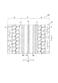
本発明の実施形態2にかかるタイヤ200について、図3を用いて説明する。タイヤ200は、ブロック陸部群20の構成が実施形態1のタイヤ100と異なるのみで、その他の点は同じであるため説明は省略し、ブロック陸部群20の構成のみを説明する。
(Embodiment 2)
A
トレッド部10は、第1および第2周方向溝11,12のタイヤ幅方向外側に、周方向に互いに等間隔に配設される複数本の第1幅方向溝21、該第1幅方向溝21とは所定の位相差で互いに等間隔に配設される複数本の第2幅方向溝22、タイヤ周方向に直線状に延びる周方向サイプ34を有する。そして、第1または第2周方向主溝11,12、第1および第2幅方向溝21,22、周方向サイプ34によって、複数の大ブロック陸部26(タイヤ赤道CLより左側のハッチング部分)が区画形成される。隣接する2つの大ブロック陸部26は、第1幅方向溝21と第2幅方向溝22とを連結する連結サイプ23aによって分割される。各大ブロック陸部26は、周方向サイプ23bによって、小ブロック陸部24,25に区画される。各小ブロック陸部24,25には、周方向中央部分に近接して2本の幅方向オープンサイプ28を配設する。なお、第1および第2幅方向溝21,22は、第1および第2周方向溝11,12よりも浅底になっている。
The
大ブロック陸部26のタイヤ幅方向外側には、幅方向に沿って延びる複数本の幅方向溝30,31が交互に配設され、これらの幅方向溝と周方向サイプ34とトレッド端Eとにより、ブロック32,33(タイヤ赤道CLよりも右側のハッチング部分)が交互に区画形成される。幅方向溝30は、トレッド端E付近よりもタイヤ幅方向内側で浅底になっており、溝幅がタイヤ幅方向内側からトレッド端Eに向かって広がるように形成される。ブロック32,33には、一端が幅方向溝30に開口し、他端がブロック32,33内で終端する周方向サイプ35,36がそれぞれ配設される。
On the outer side in the tire width direction of the large
このようなスタッドレスパターンを有するタイヤ200でも、リブ状陸部13がレール当接領域T全体にわたって位置することにより、レール当接領域Tでの剛性が高まり、不均一摩耗を抑制することができる一方、ブロック陸部群20がレール非当接領域Nに位置することにより、道路上における氷雪上性能を確保することができる。
Even in the
(実施形態3)
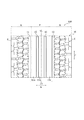
本発明の実施形態3にかかるタイヤ300について、図4を用いて説明する。
タイヤ300は、実施形態2のタイヤ200において、周方向溝15,16を設けない点以外は、タイヤ200と同様である。本実施形態では、周方向溝は2本のみ配置し、この周方向溝11,12により1つのリブ状陸部13を区画形成する。リブ状陸部13は、複数本の第1幅方向サイプ14が周方向に配列された幅方向サイプ列14a,14b,14cを有する。その他の点は、タイヤ100またはタイヤ200と同様であるため、説明を省略する。
(Embodiment 3)
A
The
この構成のタイヤ300でも、リブ状陸部13がレール当接領域T全体にわたって位置することにより、レール当接領域Tでの剛性が高まり、不均一摩耗を抑制することができる一方、ブロック陸部群20がレール非当接領域Nに位置することにより、道路上における氷雪上性能を確保することができる。
Even in the
(実施形態4)
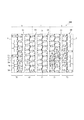
本発明の実施形態4にかかるタイヤ400について、図5を用いて説明する。タイヤ400は、実施形態2のタイヤ200において、第1幅方向サイプ14a,14b,14cを設けない点以外は、タイヤ200と同様である。本実施形態では、4本の周方向溝11,15,16,12により区画形成されたリブ状陸部13a,13b,13cには、何ら溝またはサイプは配設しない。その他の点は、タイヤ100またはタイヤ200と同様であるため、説明を省略する。
(Embodiment 4)
A
この構成のタイヤ400でも、リブ状陸部13がレール当接領域T全体にわたって位置することにより、レール当接領域Tでの剛性が高まり、不均一摩耗を抑制することができる一方、ブロック陸部群20がレール非当接領域Nに位置することにより、道路上における氷雪上性能を確保することができる。
Even in the
(実施形態5)
本発明の実施形態5にかかるタイヤ500について、図6を用いて説明する。タイヤ600は、実施形態2のタイヤ200において、第1幅方向サイプ14a,14b,14cの配設態様を変更した点以外は、タイヤ200と同様である。本実施形態では、リブ状陸部13aにはタイヤ幅方向に対して所定角度(+α)だけ傾斜した直線状の幅方向サイプ14aを配設し、リブ状陸部13cにはタイヤ幅方向に対して幅方向サイプ14aとは反対方に所定角度(−α)だけ傾斜した直線状の幅方向サイプ14cを配設する。また、リブ状陸部14bにはタイヤ幅方向に平行な直線状のサイプ14bを配置する。このように、タイヤ幅方向に対して種々の傾斜を有する複数種のサイプを配設することにより、直線状サイプであっても、タイヤ幅方向およびタイヤ周方向の両方にエッジ成分を得ることができる。その他の点は、タイヤ100またはタイヤ200と同様であるため、説明を省略する。
(Embodiment 5)
A
この構成のタイヤ500でも、リブ状陸部13がレール当接領域T全体にわたって位置することにより、レール当接領域Tでの剛性が高まり、不均一摩耗を抑制することができる一方、ブロック陸部群20がレール非当接領域Nに位置することにより、道路上における氷雪上性能を確保することができる。
Even in the
次に、本発明の効果をさらに明確にするために、実施形態1〜4に示したタイヤ100〜400(実施例1〜4)および以下に説明する比較例タイヤ600,601(比較例1,2)を用いて行った比較評価について説明する。
Next, in order to further clarify the effects of the present invention, the
(比較例タイヤ)
比較例タイヤ600について、図7を用いて説明する。タイヤ600は、トレッド部60に、タイヤ赤道CLからタイヤ幅方向両側に所定の等距離だけ離れて周方向溝64,64および周方向溝65,65を配設する。これらの周方向溝により区画される3つの中央ブロック列61は、実施形態2にかかるタイヤ200のブロック陸部群20の一部である大ブロック陸部26と同様のスタッドレスパターンである。すなわち、1つの大ブロック陸部(タイヤ赤道CLより右側のハッチング部分)は、周方向溝64、周方向溝65および4本の幅方向溝66により区画形成され、周方向サイプ68によって小ブロック62,63に区画される。隣接する2つの大ブロック陸部は、近接する2つの幅方向溝66を連結する連結サイプ67によって分割される。小ブロック62,63には、周方向中央部分に近接して2本の幅方向オープンサイプ28を配設する。周方向溝65とトレッド端Eとにより区画される側方ブロック列70は、ブロック72,76,77からなる。ブロック72は、周方向溝65よりも浅底の幅方向溝71の間に区画され、周方向中央部分に近接して2本の幅方向オープンサイプ69が配設される。ブロック76,77は、交互に配設される幅方向溝74,75の間に区画され、それぞれ周方向サイプ79が配設される。これらは、レール当接領域Tとレール非当接領域Nとでパターン基調を変更していない。
(Comparative tire)
The
比較例タイヤ601は、図8に示すトレッドパターンを有すること以外は比較例タイヤ600と同様である。このタイヤにおいても、これらは、レール当接領域Tとレール非当接領域Nとでパターン基調を変更していない。
The comparative example tire 601 is the same as the
実施例および比較例の空気入りタイヤに共通する事項は以下の通りである。
タイヤサイズ:235/70R17.5
タイヤの内部構造:1組の交差ベルトを有するラジアルタイヤ
(ベルトコード角度:周方向に対して40°〜74°,カーカス1枚)
Items common to the pneumatic tires of the examples and comparative examples are as follows.
Tire size: 235 / 70R17.5
Internal structure of tire: radial tire with a pair of cross belts (belt cord angle: 40 ° to 74 ° with respect to the circumferential direction, one carcass)
これらのタイヤをリム幅6.75インチの適用リムに装着し、750kPaの内圧を充填して、以下の性能試験を行った。結果を表1に示す。 These tires were mounted on an applicable rim having a rim width of 6.75 inches, filled with an internal pressure of 750 kPa, and the following performance tests were performed. The results are shown in Table 1.
<道路上における氷雪上性能の評価>
これらのタイヤを車両(日野プロフィア)に装着し、テストコース(氷上)で発進加速試験および制動試験を行った。発進加速試験では、初速度5.0km/hの状態からアクセルを全開に踏込んで15.0mを走行する時間を測定し、当該区間における加速度を算出し、比較例2を100として指数表示した。制動試験では、時速20kmから停止するまでの時間を測定し、比較例1タイヤを100として指数表示した。いずれも時間がかかるほど、小さな指数で表示することした。(例えば、2倍時間がかかった場合には、指数を50とする。)発進加速試験の指数と制動試験の指数の平均を表1に示した。よって、指数が大きいほど、氷上性能が優れていることを示す。雪上性能についても、テストコース(雪上)にて同様の発進加速試験および制動試験を行った。
<Evaluation of performance on ice and snow on road>
These tires were mounted on a vehicle (Hino Profia), and a start acceleration test and a braking test were performed on a test course (on ice). In the start acceleration test, the time required to travel 15.0 m while fully depressing the accelerator from the initial speed of 5.0 km / h was measured, and the acceleration in the section was calculated. In the braking test, the time from stopping at 20 km / h to stopping was measured, and indexed with the tire of Comparative Example 1 as 100. In any case, the longer the time, the smaller the index. (For example, when it takes twice the time, the index is set to 50.) Table 1 shows the average of the index of the start acceleration test and the index of the braking test. Therefore, the larger the index, the better the performance on ice. Regarding the performance on snow, the same start acceleration test and braking test were conducted on the test course (on the snow).
<摩耗性能の評価>
30%をレール走行、70%を路面走行の割合で約7000km走行したのち、レール当接領域の摩耗量とレール非当接領域の摩耗量をそれぞれ測定し、摩耗量の差を計算した。なお、試験には、標準レール(レール幅:60mm)を用い、レールとタイヤはタイヤ赤道がレール頂面の幅中心と一致するように当接し、レール当接領域は、タイヤ赤道を中心として、レール幅の120%以内の領域として設定し、トレッド幅の55%以内の領域であった。摩耗性能は、比較例2における摩耗量の差を基準(指数100)として、例えば、摩耗量の差が半分であった倍に指数を200と表示する評価方法にて評価した。よって、指数が大きいほど、不均一摩耗が抑制されていることを示す。結果を表1に示す。なお、走行路の状況により荷重バランスは一定とはならないが、概ね後輪タイヤに50%〜60%の荷重がかかり、後輪案内輪に50%〜40%の荷重がかかる条件で走行試験を行った。
<Evaluation of wear performance>
After traveling about 7000 km with 30% running on the rail and 70% running on the road surface, the amount of wear in the rail contact area and the amount of wear in the rail non-contact area were measured, and the difference in the amount of wear was calculated. In the test, a standard rail (rail width: 60 mm) was used, and the rail and the tire contacted so that the tire equator coincided with the width center of the rail top surface, and the rail contact region centered on the tire equator, It was set as an area within 120% of the rail width, and was an area within 55% of the tread width. The wear performance was evaluated by an evaluation method in which the difference in wear amount in Comparative Example 2 was used as a reference (index 100), for example, with an index indicating 200 as the index when the difference in wear amount was half. Therefore, it shows that uneven wear is suppressed, so that an index is large. The results are shown in Table 1. Although the load balance may not be constant depending on the conditions of the road, a running test is generally performed under conditions where 50% to 60% load is applied to the rear wheel tires and 50% to 40% load is applied to the rear wheel guide wheels. went.
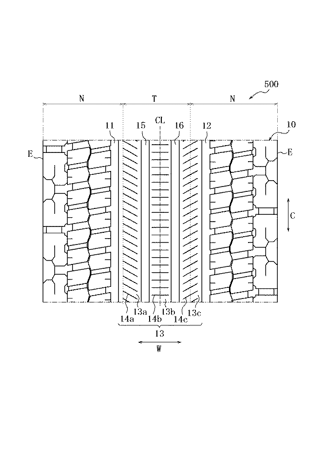
表1から明らかなように、いずれの実施例においても、比較例2を基準として道路上における氷雪上性能をさほど犠牲にすることなく、不均一摩耗を抑制する効果を十分に得ることができた。特に、実施例2で良好な結果を得た。実施例2が、実施例1に比べて道路上における氷雪上性能に優れるのは、トレッドの側方域のブロック陸部群のパターンの効果によるものである。また、実施例3ではトレッドの中央域、レール当接領域に周方向溝がないため、摩耗性能が非常に高い一方で、排雪効果が得られず、雪上性能が多少劣る。 As is clear from Table 1, in any of the Examples, the effect of suppressing uneven wear could be sufficiently obtained without sacrificing the performance on the snow and snow on the road with reference to Comparative Example 2. . In particular, good results were obtained in Example 2. The reason why Example 2 is superior in performance on ice and snow on the road as compared with Example 1 is due to the effect of the pattern of the block land portion group in the side area of the tread. Moreover, in Example 3, since there is no circumferential groove in the center area of the tread and the rail contact area, the wear performance is very high, but the snow removal effect cannot be obtained and the performance on snow is somewhat inferior.
本発明によれば、トレッド部をリブ状陸部とその両側のブロック陸部群とに区分けし、リブ状陸部がレール当接領域全体にわたって位置することにより、レール当接領域での剛性が高まり、不均一摩耗を抑制することができる一方、ブロック陸部群がレール非当接領域に位置することにより、道路上における氷雪上性能を確保することができる。 According to the present invention, the tread portion is divided into the rib-like land portion and the block land portion groups on both sides thereof, and the rib-like land portion is located over the entire rail contact region, whereby the rigidity in the rail contact region is increased. While it is possible to suppress the uneven wear, the block land portion group is located in the rail non-contact region, so that the performance on ice and snow on the road can be ensured.
100,200,300,400,500 タイヤ
10 トレッド部
11 第1周方向溝(最外周方向溝)
12 第2周方向溝(最外周方向溝)
13(13a,13b,13c) リブ状陸部
14 第1幅方向サイプ(クローズサイプ)
15 周方向溝
16 周方向溝
20 ブロック陸部群
21 第1幅方向溝
22 第2幅方向溝
23 周方向細溝
24 第1ブロック陸部
25 第2ブロック陸部
26 第1ブロック陸部列
27 第2ブロック陸部列
28 第2幅方向サイプ
T レール当接領域
N レール非当接領域
100, 200, 300, 400, 500
12 Second circumferential groove (outermost circumferential groove)
13 (13a, 13b, 13c) Rib-shaped
DESCRIPTION OF
Claims (6)
トレッド部に、
タイヤ周方向に沿って延びる少なくとも2本の周方向溝を配置して、リブ状陸部を区画形成し、
前記周方向溝のうち、タイヤ赤道面を挟んで最もタイヤ幅方向外側に位置する2本の最外周方向溝のタイヤ幅方向外側に、少なくともタイヤ幅方向に沿って延びる複数本の幅方向溝をタイヤ周方向に間隔をおいて配置して、複数個のブロック陸部からなるブロック陸部群を区画形成し、
前記リブ状陸部は、前記トレッド部のレール当接領域全体にわたって少なくとも位置し、
前記ブロック陸部群は、前記トレッド部のレール非当接領域に位置することを特徴とするタイヤ。 Tires used both on roads and on rails of tracks,
In the tread part,
Disposing at least two circumferential grooves extending along the tire circumferential direction to define a rib-like land portion;
Among the circumferential grooves, a plurality of widthwise grooves extending at least along the tire width direction are provided on the outer sides in the tire width direction of the two outermost circumferential grooves positioned on the outermost side in the tire width direction across the tire equatorial plane. Arranging the block land portion group consisting of a plurality of block land portions at intervals in the tire circumferential direction,
The rib-like land portion is located at least over the entire rail contact region of the tread portion,
The tire is characterized in that the block land portion group is located in a rail non-contact region of the tread portion.
Priority Applications (1)
| Application Number | Priority Date | Filing Date | Title |
|---|---|---|---|
| JP2011006299A JP5675381B2 (en) | 2011-01-14 | 2011-01-14 | tire |
Applications Claiming Priority (1)
| Application Number | Priority Date | Filing Date | Title |
|---|---|---|---|
| JP2011006299A JP5675381B2 (en) | 2011-01-14 | 2011-01-14 | tire |
Publications (2)
| Publication Number | Publication Date |
|---|---|
| JP2012144229A true JP2012144229A (en) | 2012-08-02 |
| JP5675381B2 JP5675381B2 (en) | 2015-02-25 |
Family
ID=46788258
Family Applications (1)
| Application Number | Title | Priority Date | Filing Date |
|---|---|---|---|
| JP2011006299A Expired - Fee Related JP5675381B2 (en) | 2011-01-14 | 2011-01-14 | tire |
Country Status (1)
| Country | Link |
|---|---|
| JP (1) | JP5675381B2 (en) |
Cited By (2)
| Publication number | Priority date | Publication date | Assignee | Title |
|---|---|---|---|---|
| JP2016088219A (en) * | 2014-10-31 | 2016-05-23 | 住友ゴム工業株式会社 | Pneumatic tire |
| JP2019182204A (en) * | 2018-04-10 | 2019-10-24 | 住友ゴム工業株式会社 | tire |
Citations (4)
| Publication number | Priority date | Publication date | Assignee | Title |
|---|---|---|---|---|
| JP2006321435A (en) * | 2005-05-20 | 2006-11-30 | Hokkaido Railway Co | Tire |
| JP2009046024A (en) * | 2007-08-21 | 2009-03-05 | Sumitomo Rubber Ind Ltd | Pneumatic tire |
| JP2009137519A (en) * | 2007-12-10 | 2009-06-25 | Bridgestone Corp | Pneumatic tire |
| JP2010012879A (en) * | 2008-07-02 | 2010-01-21 | Yokohama Rubber Co Ltd:The | Pneumatic tire |
-
2011
- 2011-01-14 JP JP2011006299A patent/JP5675381B2/en not_active Expired - Fee Related
Patent Citations (4)
| Publication number | Priority date | Publication date | Assignee | Title |
|---|---|---|---|---|
| JP2006321435A (en) * | 2005-05-20 | 2006-11-30 | Hokkaido Railway Co | Tire |
| JP2009046024A (en) * | 2007-08-21 | 2009-03-05 | Sumitomo Rubber Ind Ltd | Pneumatic tire |
| JP2009137519A (en) * | 2007-12-10 | 2009-06-25 | Bridgestone Corp | Pneumatic tire |
| JP2010012879A (en) * | 2008-07-02 | 2010-01-21 | Yokohama Rubber Co Ltd:The | Pneumatic tire |
Cited By (3)
| Publication number | Priority date | Publication date | Assignee | Title |
|---|---|---|---|---|
| JP2016088219A (en) * | 2014-10-31 | 2016-05-23 | 住友ゴム工業株式会社 | Pneumatic tire |
| JP2019182204A (en) * | 2018-04-10 | 2019-10-24 | 住友ゴム工業株式会社 | tire |
| JP7069994B2 (en) | 2018-04-10 | 2022-05-18 | 住友ゴム工業株式会社 | tire |
Also Published As
| Publication number | Publication date |
|---|---|
| JP5675381B2 (en) | 2015-02-25 |
Similar Documents
| Publication | Publication Date | Title |
|---|---|---|
| RU2401749C1 (en) | Air tire | |
| CN108099505B (en) | Tyre for vehicle wheels | |
| CN103381741B (en) | Pneumatic tire | |
| JP2002029224A (en) | Pneumatic tire | |
| US20130312887A1 (en) | Pneumatic tire | |
| JP5820466B2 (en) | Pneumatic tire | |
| EP2471671B1 (en) | Pneumatic tire | |
| US12350973B2 (en) | Tire | |
| JP2015127172A (en) | Heavy-duty pneumatic tire | |
| AU2011228471A1 (en) | Pneumatic tire | |
| WO2021002209A1 (en) | Pneumatic tire | |
| JP2014076680A (en) | Pneumatic tire | |
| JP5675381B2 (en) | tire | |
| JP5113450B2 (en) | Pneumatic tire | |
| JP4753342B2 (en) | Pneumatic radial tire | |
| JP5147315B2 (en) | Pneumatic tire | |
| JP2008132873A (en) | Pneumatic tire | |
| JP5745280B2 (en) | tire | |
| JP2006315433A (en) | Pneumatic tire | |
| JP4751070B2 (en) | Pneumatic tire | |
| CN111619290B (en) | Tire with a tire body | |
| JP5437851B2 (en) | Pneumatic tire | |
| JP5973139B2 (en) | tire | |
| JP2006298060A (en) | Pneumatic radial tire | |
| JPH09132008A (en) | Pneumatic tire |
Legal Events
| Date | Code | Title | Description |
|---|---|---|---|
| A621 | Written request for application examination |
Free format text: JAPANESE INTERMEDIATE CODE: A621 Effective date: 20140109 |
|
| A977 | Report on retrieval |
Free format text: JAPANESE INTERMEDIATE CODE: A971007 Effective date: 20140813 |
|
| A131 | Notification of reasons for refusal |
Free format text: JAPANESE INTERMEDIATE CODE: A131 Effective date: 20140826 |
|
| A521 | Request for written amendment filed |
Free format text: JAPANESE INTERMEDIATE CODE: A523 Effective date: 20141021 |
|
| TRDD | Decision of grant or rejection written | ||
| A01 | Written decision to grant a patent or to grant a registration (utility model) |
Free format text: JAPANESE INTERMEDIATE CODE: A01 Effective date: 20141202 |
|
| A61 | First payment of annual fees (during grant procedure) |
Free format text: JAPANESE INTERMEDIATE CODE: A61 Effective date: 20141224 |
|
| R150 | Certificate of patent or registration of utility model |
Ref document number: 5675381 Country of ref document: JP Free format text: JAPANESE INTERMEDIATE CODE: R150 |
|
| R250 | Receipt of annual fees |
Free format text: JAPANESE INTERMEDIATE CODE: R250 |
|
| R250 | Receipt of annual fees |
Free format text: JAPANESE INTERMEDIATE CODE: R250 |
|
| R250 | Receipt of annual fees |
Free format text: JAPANESE INTERMEDIATE CODE: R250 |
|
| R250 | Receipt of annual fees |
Free format text: JAPANESE INTERMEDIATE CODE: R250 |
|
| LAPS | Cancellation because of no payment of annual fees |