JP2012144238A - Pneumatic tire - Google Patents
Pneumatic tire Download PDFInfo
- Publication number
- JP2012144238A JP2012144238A JP2011149036A JP2011149036A JP2012144238A JP 2012144238 A JP2012144238 A JP 2012144238A JP 2011149036 A JP2011149036 A JP 2011149036A JP 2011149036 A JP2011149036 A JP 2011149036A JP 2012144238 A JP2012144238 A JP 2012144238A
- Authority
- JP
- Japan
- Prior art keywords
- thermoplastic resin
- sheet
- resin composition
- tip
- elastomer
- Prior art date
- Legal status (The legal status is an assumption and is not a legal conclusion. Google has not performed a legal analysis and makes no representation as to the accuracy of the status listed.)
- Granted
Links
Images
Classifications
-
- B—PERFORMING OPERATIONS; TRANSPORTING
- B60—VEHICLES IN GENERAL
- B60C—VEHICLE TYRES; TYRE INFLATION; TYRE CHANGING; CONNECTING VALVES TO INFLATABLE ELASTIC BODIES IN GENERAL; DEVICES OR ARRANGEMENTS RELATED TO TYRES
- B60C19/00—Tyre parts or constructions not otherwise provided for
-
- B—PERFORMING OPERATIONS; TRANSPORTING
- B29—WORKING OF PLASTICS; WORKING OF SUBSTANCES IN A PLASTIC STATE IN GENERAL
- B29D—PRODUCING PARTICULAR ARTICLES FROM PLASTICS OR FROM SUBSTANCES IN A PLASTIC STATE
- B29D30/00—Producing pneumatic or solid tyres or parts thereof
- B29D30/06—Pneumatic tyres or parts thereof (e.g. produced by casting, moulding, compression moulding, injection moulding, centrifugal casting)
- B29D30/08—Building tyres
- B29D30/20—Building tyres by the flat-tyre method, i.e. building on cylindrical drums
- B29D30/30—Applying the layers; Guiding or stretching the layers during application
- B29D30/3007—Applying the layers; Guiding or stretching the layers during application by feeding a sheet perpendicular to the drum axis and joining the ends to form an annular element
-
- B—PERFORMING OPERATIONS; TRANSPORTING
- B29—WORKING OF PLASTICS; WORKING OF SUBSTANCES IN A PLASTIC STATE IN GENERAL
- B29D—PRODUCING PARTICULAR ARTICLES FROM PLASTICS OR FROM SUBSTANCES IN A PLASTIC STATE
- B29D30/00—Producing pneumatic or solid tyres or parts thereof
- B29D30/06—Pneumatic tyres or parts thereof (e.g. produced by casting, moulding, compression moulding, injection moulding, centrifugal casting)
- B29D30/08—Building tyres
- B29D30/20—Building tyres by the flat-tyre method, i.e. building on cylindrical drums
- B29D30/30—Applying the layers; Guiding or stretching the layers during application
- B29D30/305—Applying the layers; Guiding or stretching the layers during application by feeding cut-to-length pieces in a direction parallel to the drum axis and placing the pieces side-by-side to form an annular element
-
- B—PERFORMING OPERATIONS; TRANSPORTING
- B60—VEHICLES IN GENERAL
- B60C—VEHICLE TYRES; TYRE INFLATION; TYRE CHANGING; CONNECTING VALVES TO INFLATABLE ELASTIC BODIES IN GENERAL; DEVICES OR ARRANGEMENTS RELATED TO TYRES
- B60C1/00—Tyres characterised by the chemical composition or the physical arrangement or mixture of the composition
- B60C1/0008—Compositions of the inner liner
-
- B—PERFORMING OPERATIONS; TRANSPORTING
- B60—VEHICLES IN GENERAL
- B60C—VEHICLE TYRES; TYRE INFLATION; TYRE CHANGING; CONNECTING VALVES TO INFLATABLE ELASTIC BODIES IN GENERAL; DEVICES OR ARRANGEMENTS RELATED TO TYRES
- B60C5/00—Inflatable pneumatic tyres or inner tubes
- B60C5/12—Inflatable pneumatic tyres or inner tubes without separate inflatable inserts, e.g. tubeless tyres with transverse section open to the rim
- B60C5/14—Inflatable pneumatic tyres or inner tubes without separate inflatable inserts, e.g. tubeless tyres with transverse section open to the rim with impervious liner or coating on the inner wall of the tyre
-
- B—PERFORMING OPERATIONS; TRANSPORTING
- B29—WORKING OF PLASTICS; WORKING OF SUBSTANCES IN A PLASTIC STATE IN GENERAL
- B29D—PRODUCING PARTICULAR ARTICLES FROM PLASTICS OR FROM SUBSTANCES IN A PLASTIC STATE
- B29D30/00—Producing pneumatic or solid tyres or parts thereof
- B29D30/06—Pneumatic tyres or parts thereof (e.g. produced by casting, moulding, compression moulding, injection moulding, centrifugal casting)
- B29D30/0681—Parts of pneumatic tyres; accessories, auxiliary operations
- B29D2030/0682—Inner liners
-
- B—PERFORMING OPERATIONS; TRANSPORTING
- B60—VEHICLES IN GENERAL
- B60C—VEHICLE TYRES; TYRE INFLATION; TYRE CHANGING; CONNECTING VALVES TO INFLATABLE ELASTIC BODIES IN GENERAL; DEVICES OR ARRANGEMENTS RELATED TO TYRES
- B60C5/00—Inflatable pneumatic tyres or inner tubes
- B60C5/12—Inflatable pneumatic tyres or inner tubes without separate inflatable inserts, e.g. tubeless tyres with transverse section open to the rim
- B60C5/14—Inflatable pneumatic tyres or inner tubes without separate inflatable inserts, e.g. tubeless tyres with transverse section open to the rim with impervious liner or coating on the inner wall of the tyre
- B60C2005/147—Inflatable pneumatic tyres or inner tubes without separate inflatable inserts, e.g. tubeless tyres with transverse section open to the rim with impervious liner or coating on the inner wall of the tyre characterised by the joint or splice
-
- Y—GENERAL TAGGING OF NEW TECHNOLOGICAL DEVELOPMENTS; GENERAL TAGGING OF CROSS-SECTIONAL TECHNOLOGIES SPANNING OVER SEVERAL SECTIONS OF THE IPC; TECHNICAL SUBJECTS COVERED BY FORMER USPC CROSS-REFERENCE ART COLLECTIONS [XRACs] AND DIGESTS
- Y10—TECHNICAL SUBJECTS COVERED BY FORMER USPC
- Y10T—TECHNICAL SUBJECTS COVERED BY FORMER US CLASSIFICATION
- Y10T152/00—Resilient tires and wheels
- Y10T152/10—Tires, resilient
- Y10T152/10495—Pneumatic tire or inner tube
Landscapes
- Engineering & Computer Science (AREA)
- Mechanical Engineering (AREA)
- Tires In General (AREA)
- Tyre Moulding (AREA)
Abstract
【課題】熱可塑性樹脂または熱可塑性樹脂とエラストマーをブレンドした熱可塑性樹脂組成物からなるシートと、該熱可塑性樹脂または該熱可塑性樹脂組成物と加硫接着するゴムを積層した積層体シートから形成されたインナーライナー層を有する空気入りタイヤにおいて、空気入りタイヤの走行を開始した後、インナーライナー層のスプライス部分付近においてクラックを発生することがなく耐久性に優れたタイヤを提供する。
【解決手段】熱可塑性樹脂または熱可塑性樹脂中にエラストマーをブレンドした熱可塑性樹脂組成物からなるシート2と、前記熱可塑性樹脂または前記熱可塑性樹脂組成物と加硫接着するゴム3を積層した積層体シート1の端部をラップスプライスしてインナーライナー層10を形成させた空気入りタイヤにおいて、前記熱可塑性樹脂または前記熱可塑性樹脂中にエラストマーをブレンドした熱可塑性樹脂組成物からなるシート2として、前記端部の先端が先端先鋭化処理されたものが用いられてなることを特徴とする空気入りタイヤ。
【選択図】図1A sheet comprising a thermoplastic resin or a thermoplastic resin composition obtained by blending a thermoplastic resin and an elastomer, and a laminate sheet obtained by laminating the thermoplastic resin or a rubber that is vulcanized and bonded to the thermoplastic resin composition. Provided is a pneumatic tire having an inner liner layer that is excellent in durability without causing cracks in the vicinity of a splice portion of the inner liner layer after the running of the pneumatic tire is started.
A laminate in which a sheet made of a thermoplastic resin or a thermoplastic resin composition obtained by blending an elastomer in a thermoplastic resin and a rubber 3 that is vulcanized and bonded to the thermoplastic resin or the thermoplastic resin composition are laminated. In the pneumatic tire in which the end portion of the body sheet 1 is lap spliced to form the inner liner layer 10, the sheet 2 made of the thermoplastic resin or a thermoplastic resin composition obtained by blending an elastomer in the thermoplastic resin, A pneumatic tire using a tire whose tip is sharpened at the end.
[Selection] Figure 1
Description
本発明は、空気入りタイヤに関する。 The present invention relates to a pneumatic tire.
更に詳しくは、熱可塑性樹脂または熱可塑性樹脂とエラストマーをブレンドした熱可塑性樹脂組成物からなるシートと、該熱可塑性樹脂または該熱可塑性樹脂組成物と加硫接着するゴムを積層した積層体シートを所定長さで切断し、該積層体シートの端部をスプライスし、さらに加硫成形を経て、該積層体シートから形成されたインナーライナー層を有する空気入りタイヤにおいて、該空気入りタイヤの走行を開始した後、前記スプライスされた積層体シート(インナーライナー層)のスプライス部分付近においてクラックが発生することがなく、耐久性に優れた空気入りタイヤに関するものである。 More specifically, a laminate sheet in which a sheet made of a thermoplastic resin or a thermoplastic resin composition obtained by blending a thermoplastic resin and an elastomer, and a rubber that is vulcanized and bonded to the thermoplastic resin or the thermoplastic resin composition is laminated. In a pneumatic tire having an inner liner layer formed from the laminate sheet, the laminate tire is spliced at a predetermined length, spliced at the end of the laminate sheet, and further subjected to vulcanization molding. The present invention relates to a pneumatic tire excellent in durability without cracking in the vicinity of the splice portion of the spliced laminate sheet (inner liner layer) after starting.
近年、熱可塑性樹脂または熱可塑性樹脂とエラストマーをブレンドした熱可塑性樹脂組成物からなるシート状物を空気入りタイヤのインナーライナーに使用するという提案がされ、検討されている(特許文献1)。 In recent years, it has been proposed and studied to use a sheet-like material made of a thermoplastic resin or a thermoplastic resin composition obtained by blending a thermoplastic resin and an elastomer for an inner liner of a pneumatic tire (Patent Document 1).
この熱可塑性樹脂または熱可塑性樹脂とエラストマーをブレンドした熱可塑性樹脂組成物からなるシート状物を、実際に空気入りタイヤのインナーライナーに使用するにあたっては、通常、熱可塑性樹脂または熱可塑性樹脂とエラストマーをブレンドした熱可塑性樹脂組成物のシートと、該熱可塑性樹脂または熱可塑性樹脂とエラストマーをブレンドした熱可塑性樹脂組成物のシートと加硫接着されるゴム(タイゴム)シートの積層体シートを、タイヤ成形ドラムに巻き付けてラップスプライスして、タイヤの加硫成形工程に供するという製造手法がとられる。 When a sheet-like material comprising a thermoplastic resin composition or a thermoplastic resin composition obtained by blending a thermoplastic resin and an elastomer is actually used for an inner liner of a pneumatic tire, the thermoplastic resin or the thermoplastic resin and the elastomer are usually used. And a laminate sheet of a rubber (tie rubber) sheet that is vulcanized and bonded to the thermoplastic resin or a thermoplastic resin composition blended with a thermoplastic resin and an elastomer. A manufacturing method is adopted in which the product is wound around a molding drum, lap spliced, and used for a tire vulcanization molding process.
しかし、ロール状の巻き体をなして巻かれた、該熱可塑性樹脂または熱可塑性樹脂とエラストマーをブレンドした熱可塑性樹脂組成物とタイゴム層とからなる積層体シートを、該ロール状巻き体から所要の長さ分を引き出して切断し、タイヤ成形ドラムに巻き付けて該ドラム上などにおいてラップスプライスし、更に加硫成形をしてタイヤを製造したとき、タイヤ走行開始後にインナーライナーを構成している熱可塑性樹脂または熱可塑性樹脂組成物のシートと、該熱可塑性樹脂または該熱可塑性樹脂組成物のシートと加硫接着されたタイゴムシートとが剥離してしまう場合があった。 However, a laminate sheet comprising a thermoplastic resin composition or a thermoplastic resin composition in which a thermoplastic resin and an elastomer are blended and a tie rubber layer wound in a roll form is required from the roll form. When the tire is manufactured by wrap splicing on the tire molding drum, lap splicing on the drum, etc., and further vulcanization molding, the heat that forms the inner liner after the tire starts running In some cases, the sheet of the plastic resin or the thermoplastic resin composition and the tie rubber sheet vulcanized and bonded to the thermoplastic resin or the sheet of the thermoplastic resin composition are peeled off.
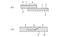
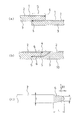
これを図で説明すると、図2(a)に示したように、熱可塑性樹脂または熱可塑性樹脂とエラストマーをブレンドした熱可塑性樹脂組成物からなるシート2とタイゴム層3とからなる積層体シート1は、刃物などで所要サイズ(長さ)に切断されて、タイヤ成形ドラム上にて、その両端部にラップスプライス部Sを設けて環状を成すようにしてスプライスされる。なお、該積層体シート1は、1枚の使用のときは、その両端部がスプライスされて環状を成すように形成され、あるいは複数枚の使用のときはそれら相互の端部同士がスプライスされて環状を成すように形成されるものなどである。
This will be described with reference to the drawings. As shown in FIG. 2 (a), a
そして、更にタイヤの製造に必要なパーツ材(図示せず)が巻かれ、ブラダーで加硫成形される。加硫成形後においては、図2(b)にモデル図で示したように、熱可塑性樹脂または熱可塑性樹脂とエラストマーをブレンドした熱可塑性樹脂組成物のシート2とタイゴム層3からなるインナーライナー層10が形成され、スプライス部S付近では、熱可塑性樹脂または上述の熱可塑性樹脂組成物からなるシート2が、露出している部分とタイゴム層の中に埋設している部分が形成されている。
Further, a part material (not shown) necessary for manufacturing the tire is wound and vulcanized with a bladder. After the vulcanization molding, as shown in a model diagram in FIG. 2B, an inner liner layer comprising a
そして、上述した熱可塑性樹脂または熱可塑性樹脂組成物のシート2と加硫接着されたタイゴムシート3とが剥離してしまう現象は、特に、図2(b)で示した熱可塑性樹脂組成物のシート2が露出していてかつその先端部付近4などにおいて発生し、まずクラックが発生し、それがさらに進んでシートの剥離現象へと進行していく。
The phenomenon in which the above-described thermoplastic resin or thermoplastic
本発明の目的は、上述したような点に鑑み、熱可塑性樹脂または熱可塑性樹脂とエラストマーをブレンドした熱可塑性樹脂組成物からなるシートと、該熱可塑性樹脂または該熱可塑性樹脂組成物と加硫接着するゴムを積層した積層体シートを所定長さで切断し、もしくは、熱可塑性樹脂または熱可塑性樹脂とエラストマーをブレンドした熱可塑性樹脂組成物からなるシートと該熱可塑性樹脂または該熱可塑性樹脂組成物と加硫接着するゴムを、それぞれ所定の長さに切断し、それらを積層した積層シートを、該積層体シートの端部をラップスプライスし、さらに加硫成形を経て、該積層体シートから形成されたインナーライナー層を有する空気入りタイヤにおいて、該空気入りタイヤの走行を開始した後、前記スプライスされた積層体シート(インナーライナー層)のスプライス部分付近においてクラックを発生することがなく、耐久性に優れた空気入りタイヤを提供することにある。 In view of the above-described points, an object of the present invention is to provide a sheet made of a thermoplastic resin or a thermoplastic resin composition obtained by blending a thermoplastic resin and an elastomer, the thermoplastic resin or the thermoplastic resin composition, and a vulcanization. A sheet made of a thermoplastic resin composition obtained by cutting a laminated sheet laminated with rubber to be bonded to a predetermined length, or blending a thermoplastic resin or a thermoplastic resin and an elastomer, and the thermoplastic resin or the thermoplastic resin composition The rubber to be vulcanized and bonded to the product is cut into predetermined lengths, and the laminated sheet obtained by laminating them is lap spliced at the end of the laminated sheet, and further vulcanized and molded from the laminated sheet. In the pneumatic tire having the formed inner liner layer, the spliced laminate sheet after the running of the pneumatic tire is started Without generating a crack in the vicinity of the splice portion of the inner liner layer) is to provide a pneumatic tire having excellent durability.
上述した目的を達成する本発明の空気入りタイヤは、以下の(1)の構成を有する。
(1)熱可塑性樹脂または熱可塑性樹脂中にエラストマーをブレンドした熱可塑性樹脂組成物からなるシート2と、前記熱可塑性樹脂または前記熱可塑性樹脂組成物と加硫接着するゴム3を積層した積層体シート1の端部をラップスプライスしてインナーライナー層10を形成させた空気入りタイヤにおいて、前記熱可塑性樹脂または前記熱可塑性樹脂中にエラストマーをブレンドした熱可塑性樹脂組成物からなるシート2として、前記端部の先端が先端先鋭化処理されたものが用いられてなることを特徴とする空気入りタイヤ。
The pneumatic tire of the present invention that achieves the above-described object has the following configuration (1).
(1) A laminate in which a thermoplastic resin or a
かかる本願発明の空気入りタイヤにおいて、以下の(2)〜(7)のいずれかの構成からなることが好ましい。
(2)前記先端先鋭化処理が、前記熱可塑性樹脂または前記熱可塑性樹脂中にエラストマーをブレンドした熱可塑性樹脂組成物からなるシート2の先端から、(t×1/3)長さ分内側に入った位置で、厚さT(μm)が、0.1t≦T≦0.8tを満足する関係を有することを特徴とする上記(1)記載の空気入りタイヤ。
In the pneumatic tire of the present invention, it is preferable that the pneumatic tire has any one of the following configurations (2) to (7).
(2) The tip sharpening treatment is performed inward by (t × 1/3) length from the tip of the
ここで、t:熱可塑性樹脂または熱可塑性樹脂中にエラストマーをブレンドした熱可塑性樹脂組成物からなるシート2の非先端先鋭化処理部分のタイヤ周方向平均厚さ(μm)
T:熱可塑性樹脂または熱可塑性樹脂中にエラストマーをブレンドした熱可塑性樹脂組成物からなるシート2の先端から、(t×1/3)長さ分内側に入った位置でのシート2の厚さ(μm)
(3)前記先端先鋭化処理された部分の長さLが、L=(1.0〜20)×t(μm)長さ分内側に入った位置まであることを特徴とする上記(1)または(2)記載の空気入りタイヤ。
(4)前記先端先鋭化処理された部分の長さLが、L=(1.0〜2.5)×t(μm)長さ分、先端から内側に入った位置まであることを特徴とする上記(1)〜(3)のいずれかに記載の空気入りタイヤ。
(5)前記空気入りタイヤが加硫成形により形成されたものであり、前記先端尖鋭化処理が該加硫成形以前になされているものであることを特徴とする上記(1)〜(4)のいずれかに記載の空気入りタイヤ。
(6)前記シート2が、熱可塑性樹脂中にエラストマーをブレンドした熱可塑性樹脂組成物からなるものであり、前記先端先鋭化処理された先端部分の表面では、該エラストマーが前記熱可塑性樹脂の被膜で覆われていることを特徴とする上記(1)〜(5)のいずれかに記載の空気入りタイヤ。
(7)前記積層体シート1が1枚もしくは複数枚が用いられ、1枚の場合はその両端部が、複数枚の場合は相互の端部が、ラップスプライスされて前記インナーライナー層10を形成してなる上記(1)〜(6)のいずれかに記載の空気入りタイヤ。
Here, t: average thickness (μm) in the tire circumferential direction of the non-tip sharpened portion of the
T: Thickness of the
(3) The above-mentioned (1), wherein the length L of the portion subjected to the tip sharpening process is as long as L = (1.0 to 20) × t (μm) inward. Or the pneumatic tire of (2) description.
(4) The length L of the tip sharpened portion is L = (1.0 to 2.5) × t (μm) length from the tip to the inside position. The pneumatic tire according to any one of (1) to (3) above.
(5) The pneumatic tire described above (1) to (4), wherein the pneumatic tire is formed by vulcanization molding, and the tip sharpening treatment is performed before the vulcanization molding. The pneumatic tire according to any one of the above.
(6) The
(7) One or a plurality of the
請求項1にかかる本発明によれば、タイヤ走行開始後に、インナーライナー層を構成している熱可塑性樹脂または熱可塑性樹脂組成物のシートと該熱可塑性樹脂または該可塑性樹脂組成物のシートと加硫接着されたタイゴムシートとが、相互間で剥離することがなく、優れた耐久性を有する空気入りタイヤが提供される。 According to the first aspect of the present invention, after the tire running is started, the thermoplastic resin or the thermoplastic resin composition sheet constituting the inner liner layer and the thermoplastic resin or the thermoplastic resin composition sheet are added to the sheet. There is provided a pneumatic tire having excellent durability without causing the sulfur-bonded tie rubber sheet to peel off from each other.
請求項2〜請求項6のいずれかにかかる本発明の空気入りタイヤによれば、上記請求項1にかかる本発明の効果を有するとともに、その効果をより確実にかつより効果的に得ることができる。
According to the pneumatic tire of the invention according to any one of
請求項7にかかる本発明によれば、積層体シートが、1枚もしくは複数枚用いられて、それらの端部(1枚の場合はその両端部、複数枚の場合は相互の端部同士)がラップスプライスされて、環状を形成させてインナーライナー層10を形成する場合、上記請求項1にかかる本発明の効果を有する耐久性に優れた空気入りタイヤが提供される。
According to the present invention according to claim 7, one or a plurality of laminate sheets are used and their end portions (both end portions in the case of one sheet, and mutual end portions in the case of a plurality of sheets). When the
以下、更に詳しく本発明の空気入りタイヤの製造方法について、説明する。 Hereinafter, the manufacturing method of the pneumatic tire of the present invention will be described in more detail.
本発明の空気入りタイヤは、熱可塑性樹脂または熱可塑性樹脂中にエラストマーをブレンドした熱可塑性樹脂組成物からなるシート2と、前記熱可塑性樹脂または前記熱可塑性樹脂組成物と加硫接着するゴム3を積層した積層体シート1の端部をラップスプライスしてインナーライナー層10を形成させた空気入りタイヤにおいて、前記熱可塑性樹脂または前記熱可塑性樹脂中にエラストマーをブレンドした熱可塑性樹脂組成物からなるシート2として、その先端が先端先鋭化処理されたものが用いられてなることを特徴とする。
The pneumatic tire of the present invention includes a
本発明者らは、従来方法によるものの不都合点であるインナーライナー層を構成している熱可塑性樹脂または熱可塑性樹脂中にエラストマーをブレンドした熱可塑性樹脂組成物のシートと、前記熱可塑性樹脂または前記可塑性樹脂組成物のシートと加硫接着されたタイゴムシートとが相互間で剥離する原因について種々検討した結果、以下の知見を得た。 The inventors of the present invention provide a thermoplastic resin constituting the inner liner layer, which is a disadvantage of the conventional method, or a sheet of a thermoplastic resin composition in which an elastomer is blended in the thermoplastic resin, the thermoplastic resin or the As a result of various investigations on the cause of peeling between the sheet of the plastic resin composition and the vulcanized and bonded tie rubber sheet, the following knowledge was obtained.
すなわち、上述の積層体シート1を、通常の方法で準備した場合、図2(a)、(b)に示した積層体シート1の両端のラップスプライス部S付近では、上下に存在する剛性の大きな熱可塑性樹脂または熱可塑性樹脂中にエラストマーをブレンドした熱可塑性樹脂組成物のシート2に挟まれたゴム部に大きな応力が発生し、そのため、熱可塑性樹脂または熱可塑性樹脂組成物のシート2の先端部付近4などにおいてクラックの発生や、さらに該クラックが大きくなって剥離が発生すると考えられるものであった。
That is, when the above-described
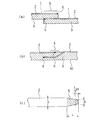
これに対して、本発明の空気入りタイヤにおいては、図1に示したように、積層体シート1を所定長さに切断して準備するに際して、熱可塑性樹脂または熱可塑性樹脂中にエラストマーをブレンドした熱可塑性樹脂組成物のシート2として、その先端付近にて先端先鋭化処理されている部分5が形成されたものを準備するのである。これにより、上下にペアで存在する剛性の大きな熱可塑性樹脂または熱可塑性樹脂中にエラストマーをブレンドした熱可塑性樹脂組成物のシート2の厚さが、先端部付近4では薄いものとなり、また、シート2とゴム部3との界面の面積が広くなることから応力は分散され、これら理由により、シート2に挟まれたゴム部3に発生する応力は小さくかつ分散もされて、緩和されたものとなる。このことが、タイヤ使用の開始後に、該熱可塑性樹脂または該熱可塑性樹脂組成物のシート2と加硫接着されたタイゴムシート3との間で互いの剥離現象を起こすことを防止するのに効果を発揮する。
On the other hand, in the pneumatic tire of the present invention, as shown in FIG. 1, when the
本発明において、熱可塑性樹脂または熱可塑性樹脂中にエラストマーをブレンドした熱可塑性樹脂組成物のシート2が、その先端で「先端先鋭化処理をされている」とは、通常の刃物を使用して常温下で積層シート1を切断しただけの場合では、シートの幅方向から見たとき、その切断面はシート2の平面方向に垂直な切断端面を有するが(図2(a))、本発明にかかるシート2では、その切断端面が、図1の(a)〜(c)にモデル的に示したように、先鋭化処理されて先端に向かって徐々に細くなっている先端先鋭化処理部分5を有しているものであり、そのような側面形状になるように、物理的または化学的な処理もしくはそれら双方の処理あるいはそれらの処理と熱的処理の組合せなどによる処理がなされていることをいうものである。
In the present invention, the
その処理は、所望のラップスプライスに適応させた所定長さに積層シート1を切断するのと同時になされるものであってもよく、あるいは、所定長さに切断後になされるものであってもよい。さらに、あるいは、積層シートにされる前の段階で、熱可塑性樹脂または熱可塑性樹脂中にエラストマーをブレンドした熱可塑性樹脂組成物のシート2の先端部または/およびゴム3の先端部に対して先端先鋭化処理を施して、しかる後に、両者を積層・接合して積層シート1を形成せしめるようにしてもよい。いずれにあっても、積層シートの先端部での先鋭化形態が実現できて、上述した応力の分散と緩和効果が得られるものである。また、あるいは、先端先鋭化処理がタイヤの加硫成形後に行われるものでもよく、特に該先端尖鋭化処理が、後述するような物理的処理を主とする処理である場合には、タイヤの加硫成形後に行うことも処理のしやすさや的確さなどの点での利点がある。
The processing may be performed simultaneously with cutting the
「先鋭化処理されて先端に向かって徐々に細くなっている形状」は、先端付近において、「丸味」が付けられている程度のものでもよく、そのような丸味を有する形状にされているだけでも、上述したクラックの発生、剥離の発生の防止効果は顕著に認められる。このシート2の先端での先端先鋭化処理がされた形態は、加硫前と加硫後とでその先鋭形態が実質的に維持されるものであり、タイヤとしての使用開始後に該クラックの発生や剥離の発生の防止効果が有効に発揮されるのである。
“Shape that has been sharpened and gradually becomes narrower toward the tip” may be a shape that has “roundness” in the vicinity of the tip, and has only such a rounded shape. However, the effect of preventing the occurrence of cracks and peeling as described above is remarkably recognized. The form in which the tip sharpening process is performed at the tip of the
上述したように、シート2の先端での先端先鋭化処理は、丸味が付けられている程度でも効果を発揮するが、特に、高い効果を安定して得るには、該先端先鋭化処理が、前記熱可塑性樹脂または前記熱可塑性樹脂中にエラストマーをブレンドした熱可塑性樹脂組成物からなるシート2の先端から、(t×1/3)長さ分内側に入った位置で、厚さT(μm)が、0.1t≦T≦0.8tを満足する関係を有するようになされていることが好ましい。図1(c)はこの関係を示したものであり、先端から(t/3)分だけ内側に入った位置での厚さのレベルについての関係であり、好ましくは、0.2t≦T≦0.6tである。ここで、tは、熱可塑性樹脂または熱可塑性樹脂中にエラストマーをブレンドした熱可塑性樹脂組成物からなるシート2の非先端先鋭化処理部分のタイヤ周方向平均厚さ(μm)であり、Tは、熱可塑性樹脂または熱可塑性樹脂中にエラストマーをブレンドした熱可塑性樹脂組成物からなるシート2の先端から、(t×1/3)長さ分内側に入った位置でのシート2の厚さ(μm)である。
As described above, the tip sharpening process at the tip of the
また、先端先鋭化処理された部分(図1(c)で5)の長さLは、L=(1.0〜20)×t(μm)であること、すなわち、該Lの長さ分だけ内側に入った位置まで先端先鋭化処理部であることが好ましい。より好ましくは、L=(1.0〜10)×t(μm)であること、さらに好ましくは、L=(1.0〜2.5)×t(μm)である。 Further, the length L of the portion sharpened at the tip (5 in FIG. 1C) is L = (1.0 to 20) × t (μm), that is, the length L It is preferable that the tip sharpening processing unit is located only up to the position inside. More preferably, L = (1.0 to 10) × t (μm), and more preferably L = (1.0 to 2.5) × t (μm).
先端先鋭化処理されている部分の形状は、図1(a)〜(c)に示したような側断面形状で、きれいなテーパー状を呈していることが望ましいが、きれいなテーパー状でなくても効果は発揮できるので、非対称のテーパー状のものや、テーパー状に先鋭化されていて、かつ一方向に(例えばタイゴム層側に)湾曲している形状や、多少の凹凸を有した形態や、前述した丸味付けされているようなもの等であってもよい。 The shape of the tip sharpened portion is preferably a side cross-sectional shape as shown in FIGS. 1 (a) to 1 (c) and has a clean taper shape. Since the effect can be exhibited, an asymmetric taper shape, a shape that is sharpened in a taper shape and curved in one direction (for example, on the tie rubber layer side), a form with some unevenness, It may be the one that is rounded as described above.
本発明において、このシート2の先端への先端先鋭化処理は、例えば、ロール状の巻き体からシート2を所要長さ分を引き出して、シート2に張力をかけながら電熱線などのヒートカッタを当てて熱切断を行うこと、あるいは、通常の刃物での切断後、シートの長さ方向の切断端面に、アルカリや酸などの化学的溶解処理をすること、あるいはグラインダややすり等を用いた各種研磨などの物理的処理をすることにより行うことができる。中では、シート2に張力をかけながら鈍角な刃先をもつヒートカッタを当てて熱切断を行うこと等が、コントロールのしやすさや設備面やコスト面から好ましい。
In the present invention, the tip sharpening process to the tip of the
なお、熱切断により行う場合で、特に、前記シート2が熱可塑性樹脂中にエラストマーをブレンドした熱可塑性樹脂組成物からなるものであるときは、先端先鋭化処理された先端部分の表面では熱を受けて前記熱可塑性樹脂が流動されながら切断されていることから、切断端付近の表面に存在する該エラストマーが該熱可塑性樹脂の被膜で覆われて得られる現象が生ずる。こうして得られたシート2は、エラストマーが露出している状態で加硫接着される場合と比較して、より強い加硫接着状態が得られるので、その点でも前記したクラックの発生や剥離の発生の防止に効果的なものである。一般に、積層体シートの切断面上にエラストマーが露出して存在していると、該エラストマーが加硫接着を阻害して、該熱可塑性樹脂組成物のシートとタイゴムシートとの間の加硫接着力を低くさせるので、エラストマーが極力露出しないようにして先端先鋭をすることが好ましく、上述した熱切断方式は、この点で好ましいものである。熱切断方式をとる場合は、該熱切断の熱で溶融し流動される熱可塑性樹脂が、切断面上にあるエラストマーの全部を覆うことが十分にできる条件で熱切断することが好ましく、具体的には、(熱可塑性樹脂の融点+30℃)〜(熱可塑性樹脂の融点+180℃)の範囲内の切断温度で行うのが好ましく、切断温度がこの範囲よりも低い場合には熱可塑性樹脂を流動させることが難しく、エラストマーの被覆を十分に行うことは難しい。また、切断温度がこの範囲よりも高い場合には熱可塑性樹脂組成物やタイゴムシートを劣化させることがあり好ましくない。熱切断は、ヒートカッタを用いて行うこと、あるいはレーザーを用いて行うことが好ましい。熱を加えるとともに張力を加えて熱切断することが重要であり、さらに、加圧してヒートカッタを当てて切断するようにしてもよい。また、超音波カッタや高周波カッタなども同様に使用できる。
In the case of thermal cutting, particularly when the
また、上記した熱切断による、「切断端付近の表面に存在するエラストマーが、熱可塑性樹脂の被膜で覆われて得られる現象」の効果は、熱を利用しないで切断した端部に、切断後、熱風や加熱プレートあるいは加熱ローラを適宜に当てる処理を行うことなどによっても得ることができる。また、それらの処理は、積層シートにされる前の段階で、熱可塑性樹脂または熱可塑性樹脂中にエラストマーをブレンドした熱可塑性樹脂組成物のシート2の単体で先端先鋭化処理をした場合には、その単体の状態で行うことができる。
In addition, the effect of “the phenomenon that is obtained when the elastomer existing on the surface near the cutting edge is covered with a thermoplastic resin film” by the above-described thermal cutting is the effect of cutting the end without cutting heat. It can also be obtained by performing a process of appropriately applying hot air, a heating plate or a heating roller. In addition, when the tip sharpening treatment is performed with a single piece of the thermoplastic resin or a thermoplastic
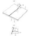
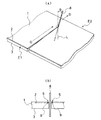
図3(a)は、熱可塑性樹脂または熱可塑性樹脂組成物からなるシート2と該熱可塑性樹脂または熱可塑性樹脂組成物と加硫接着するゴム3を積層した積層体シート1を、所望のラップスプライスに適応させた所定長さに切断をする際に、熱可塑性樹脂または熱可塑性樹脂組成物からなるシート2の先端が先鋭化処理された状態で得ることを実現する切断手法の1例を示したモデル図であり、ヒートカッタ8を積層体シート1の長手方向に傾斜角αで傾斜させて(積層体シートの幅方向には、傾けずに)、ヒートカッタ8を矢印D方向に進行させて熱溶断する例を示している。同図(b)はその切断手法によるヒートカッタ8と熱可塑性樹脂または熱可塑性樹脂組成物2のシートの先端部9の形態との関係をモデル的に示したものであり、積層体の先端は切断端部で先端が先鋭化されている。傾斜角αは、30〜60度の範囲が好ましい。
FIG. 3A shows a
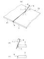
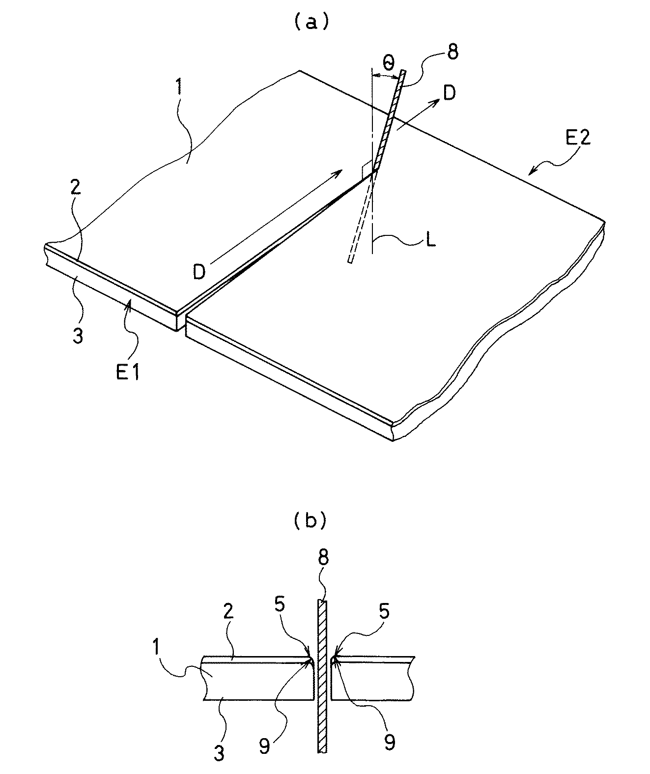
図4(a)は、ヒートカッタを用いて熱可塑性樹脂または熱可塑性樹脂組成物からなるシート2の熱切断を行う際に、特に好ましく採用され得る切断手法を示したものであり、ヒートカッタ8を、熱可塑性樹脂または熱可塑性樹脂組成物からなるシート2の側面に該シート2の上方空間と下方空間に跨って交差するように当て、かつ、ヒートカッタ8を進行させる方向D(この場合、熱可塑性樹脂または熱可塑性樹脂組成物からなるシート2の幅方向と同一の方向)に向けて傾斜角θで傾斜させた状態で熱可塑性樹脂または熱可塑性樹脂組成物からなるシート2の一方端E1から他方端E2まで進行させて熱切断を行う手法によるのが好ましい。
FIG. 4 (a) shows a cutting method that can be particularly preferably employed when the
本発明者らの知見によれば、この手法による場合、ヒートカッタ8を進行させる際にヒートカッタ8を傾斜させるレベルは、シート2の垂線Lと10°〜60°の傾斜角度(ヒートカッタ8の進行方向Dと直角方向の傾斜角度)αをもって傾斜した状態とするのが好ましい。ヒートカッタ8をこのように一方端E1側から他端E2側に向けて交差させて進めて切断する方式にすることは、ヒートカッタ8を熱可塑性樹脂または熱可塑性樹脂組成物からなるシート2の全面に一度に押し当てて熱切断をする場合と比べて、熱が逃げてしまうことが少なく、確実にきれいな切断面状態で切断することができる点で好ましいのである。この方式で得られる切断端の状態は、図4(c)にモデル図を示した如くであり、熱可塑性樹脂または熱可塑性樹脂組成物からなるシート2の先端部9は、先鋭化処理されて、先端先鋭化処理されている部分5が形成される。これは、傾斜角度(ヒートカッタ8の進行方向D(切断線方向)と直角方向の傾斜角度)αで傾斜させた状態で進行させたことにより、熱可塑性樹脂または熱可塑性樹脂組成物からなるシート2の先端部9が下方に押圧作用を受けながら溶融されて切断されたためと考えられるものである。
According to the knowledge of the present inventors, in the case of this method, when the
さらに、図5(a)に示したように、熱可塑性樹脂または熱可塑性樹脂組成物からなるシート2と該シートと加硫接着するゴム3とを積層した積層体シート1をヒートカッタ8を傾斜角度(ヒートカッタ8の進行方向D(切断線方向)と同一方向の傾斜角度)θで傾斜させて切断してもよい。本発明者らの知見によれば、この方式で得られる切断端の状態は、図5(b)にモデル図を示した如くであり、熱可塑性樹脂組成物2のシートの先端部9は、先鋭化されて先端先鋭化処理されている部分5が形成され、かつ、通常は、タイゴム3のシート層の先端側に湾曲して回り込んでいるものとして得られる。これは、傾斜角θで傾斜させた状態でヒートカッタ8を進行させることにより、熱可塑性樹脂組成物2のシートの先端部が下方(タイゴム3のシート層のある方向)に押圧作用を受けながら溶融されて切断されるためと考えられるものである。この図5(b)に示したような、熱可塑性樹脂組成物2のシートの先端部が多少湾曲したような形態の積層体の状態のものであっても、本発明者らの知見によれば、それがタイヤの加硫成形工程に供された場合には、該工程中では加硫ブラダーに押されるため、最終的に、図1(C)のようにほぼ真っ直ぐな先鋭形状を有したものを得ることができる。
Further, as shown in FIG. 5 (a), the
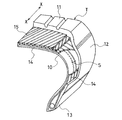
図6は、本発明にかかる空気入りタイヤの形態の1例を示した一部破砕斜視図である。空気入りタイヤTは、トレッド部11の左右にサイドウォール部12とビード部13を連接するように設けている。そのタイヤ内側には、タイヤの骨格たるカーカス層14が、タイヤ幅方向には左右のビード13、13間に跨るように設けられている。トレッド部11に対応するカーカス層4の外周側にはスチールコードからなる2層のベルト層15が設けられている。矢印Xはタイヤ周方向を示している。カーカス層14の内側には、インナーライナー層10が配され、そのラップスプライス部Sがタイヤ幅方向に延びて存在している。
FIG. 6 is a partially broken perspective view showing an example of the form of the pneumatic tire according to the present invention. The pneumatic tire T is provided so that the
本発明にかかる空気入りタイヤでは、タイヤ内周面上でこのラップスプライス部S付近で従来は生じやすかったクラックの発生、インナーライナー層10を形成している熱可塑性樹脂または熱可塑性樹脂組成物からなるシート2とタイゴム層3の間のクラックの発生、剥離の発生が抑制されて耐久性が著しく向上するものである。ラップスプライス部Sの重なり長さは、タイヤサイズにもよるが、好ましくは7〜20mm程度、より好ましくは8〜15mm程度とするのがよい。重なり長さが長すぎると、ユニフォミティーが悪化する方向であり、短すぎると成形時にスプライス部が開いてしまうおそれがあるためである。
In the pneumatic tire according to the present invention, from the thermoplastic resin or thermoplastic resin composition forming the
本発明で用いることのできる熱可塑性樹脂としては、例えば、ポリアミド系樹脂〔例えば、ナイロン6(N6)、ナイロン66(N66)、ナイロン46(N46)、ナイロン11(N11)、ナイロン12(N12)、ナイロン610(N610)、ナイロン612(N612)、ナイロン6/66共重合体(N6/66)、ナイロン6/66/610共重合体(N6/66/610)、ナイロンMXD6(MXD6)、ナイロン6T、ナイロン9T、ナイロン6/6T共重合体、ナイロン66/PP共重合体、ナイロン66/PPS共重合体〕及びそれらのN−アルコキシアルキル化物、例えば、ナイロン6のメトキシメチル化物、ナイロン6/610共重合体のメトキシメチル化物、ナイロン612のメトキシメチル化物、ポリエステル系樹脂〔例えば、ポリブチレンテレフタレート(PBT)、ポリエチレンテレフタレート(PET)、ポリエチレンイソフタレート(PEI)、PET/PEI共重合体、ポリアリレート(PAR)、ポリブチレンナフタレート(PBN)、液晶ポリエステル、ポリオキシアルキレンジイミドジ酸/ポリブチレンテレフタレート共重合体などの芳香族ポリエステル〕、ポリニトリル系樹脂〔例えば、ポリアクリロニトリル(PAN)、ポリメタクリロニトリル、アクリロニトリル/スチレン共重合体(AS)、(メタ)アクリロニトリル/スチレン共重合体、(メタ)アクリロニトリル/スチレン/ブタジエン共重合体〕、ポリメタクリレート系樹脂〔例えば、ポリメタクリル酸メチル(PMMA)、ポリメタクリル酸エチル〕、ポリビニル系樹脂〔例えば、酢酸ビニル、ポリビニルアルコール(PVA)、ビニルアルコール/エチレン共重合体(EVOH)、ポリ塩化ビニリデン(PDVC)、ポリ塩化ビニル(PVC)、塩化ビニル/塩化ビニリデン共重合体、塩化ビニリデン/メチルアクリレート共重合体、塩化ビニリデン/アクリロニトリル共重合体(ETFE)〕、セルロース系樹脂〔例えば、酢酸セルロース、酢酸酪酸セルロース〕、フッ素系樹脂〔例えば、ポリフッ化ビニリデン(PVDF)、ポリフッ化ビニル(PVF)、ポリクロルフルオロエチレン(PCTFE)、テトラフロロエチレン/エチレン共重合体〕、イミド系樹脂〔例えば、芳香族ポリイミド(PI)〕等を好ましく用いることができる。 Examples of the thermoplastic resin that can be used in the present invention include polyamide resins [for example, nylon 6 (N6), nylon 66 (N66), nylon 46 (N46), nylon 11 (N11), nylon 12 (N12). , Nylon 610 (N610), nylon 612 (N612), nylon 6/66 copolymer (N6 / 66), nylon 6/66/610 copolymer (N6 / 66/610), nylon MXD6 (MXD6), nylon 6T, nylon 9T, nylon 6 / 6T copolymer, nylon 66 / PP copolymer, nylon 66 / PPS copolymer] and their N-alkoxyalkylated products, for example, methoxymethylated products of nylon 6, nylon 6 / 610 copolymer methoxymethylated product, nylon 612 methoxymethylated product, polyester Resin [for example, polybutylene terephthalate (PBT), polyethylene terephthalate (PET), polyethylene isophthalate (PEI), PET / PEI copolymer, polyarylate (PAR), polybutylene naphthalate (PBN), liquid crystal polyester, poly Aromatic polyester such as oxyalkylene diimide diacid / polybutylene terephthalate copolymer], polynitrile resin [for example, polyacrylonitrile (PAN), polymethacrylonitrile, acrylonitrile / styrene copolymer (AS), (meth) acrylonitrile / Styrene copolymer, (meth) acrylonitrile / styrene / butadiene copolymer], polymethacrylate resins [for example, polymethyl methacrylate (PMMA), polyethyl methacrylate], polyvinylidene Resin [for example, vinyl acetate, polyvinyl alcohol (PVA), vinyl alcohol / ethylene copolymer (EVOH), polyvinylidene chloride (PDVC), polyvinyl chloride (PVC), vinyl chloride / vinylidene chloride copolymer, vinylidene chloride / Methyl acrylate copolymer, vinylidene chloride / acrylonitrile copolymer (ETFE)], cellulose resin [eg, cellulose acetate, cellulose acetate butyrate], fluorine resin [eg, polyvinylidene fluoride (PVDF), polyvinyl fluoride ( PVF), polychlorofluoroethylene (PCTFE), tetrafluoroethylene / ethylene copolymer], an imide resin [for example, aromatic polyimide (PI)] and the like can be preferably used.
また、本発明で使用できる熱可塑性樹脂組成物を構成する熱可塑性樹脂とエラストマーは、熱可塑性樹脂については上述のものを使用できる。エラストマーとしては、例えば、ジエン系ゴム及びその水添物〔例えば、天然ゴム(NR)、イソプレンゴム(IR)、エポキシ化天然ゴム、スチレンブタジエンゴム(SBR)、ブタジエンゴム(BR、高シスBR及び低シスBR)、ニトリルゴム(NBR)、水素化NBR、水素化SBR〕、オレフィン系ゴム〔例えば、エチレンプロピレンゴム(EPDM、EPM)、マレイン酸変性エチレンプロピレンゴム(M−EPM)、ブチルゴム(IIR)、イソブチレンと芳香族ビニル又はジエン系モノマー共重合体、アクリルゴム(ACM)、アイオノマー〕、含ハロゲンゴム〔例えば、Br−IIR、CI−IIR、臭素化イソブチレン−p−メチルスチレン共重合体(BIMS)、クロロプレンゴム(CR)、ヒドリンゴム(CHR)、クロロスルホン化ポリエチレンゴム(CSM)、塩素化ポリエチレンゴム(CM)、マレイン酸変性塩素化ポリエチレンゴム(M−CM)〕、シリコンゴム〔例えば、メチルビニルシリコンゴム、ジメチルシリコンゴム、メチルフェニルビニルシリコンゴム〕、含イオウゴム〔例えば、ポリスルフィドゴム〕、フッ素ゴム〔例えば、ビニリデンフルオライド系ゴム、含フッ素ビニルエーテル系ゴム、テトラフルオロエチレン−プロピレン系ゴム、含フッ素シリコン系ゴム、含フッ素ホスファゼン系ゴム〕、熱可塑性エラストマー〔例えば、スチレン系エラストマー、オレフィン系エラストマー、エステル系エラストマー、ウレタン系エラストマー、ボリアミド系エラストマー〕等を好ましく使用することができる。 Further, as the thermoplastic resin and the elastomer constituting the thermoplastic resin composition that can be used in the present invention, those described above for the thermoplastic resin can be used. Examples of the elastomer include diene rubber and hydrogenated products thereof [for example, natural rubber (NR), isoprene rubber (IR), epoxidized natural rubber, styrene butadiene rubber (SBR), butadiene rubber (BR, high cis BR and Low cis BR), nitrile rubber (NBR), hydrogenated NBR, hydrogenated SBR], olefin rubber [for example, ethylene propylene rubber (EPDM, EPM), maleic acid modified ethylene propylene rubber (M-EPM), butyl rubber (IIR) ), Isobutylene and aromatic vinyl or diene monomer copolymer, acrylic rubber (ACM), ionomer], halogen-containing rubber [for example, Br-IIR, CI-IIR, brominated isobutylene-p-methylstyrene copolymer ( BIMS), chloroprene rubber (CR), hydrin rubber (CHR) Chlorosulfonated polyethylene rubber (CSM), chlorinated polyethylene rubber (CM), maleic acid modified chlorinated polyethylene rubber (M-CM)], silicone rubber [eg methyl vinyl silicone rubber, dimethyl silicone rubber, methyl phenyl vinyl silicone rubber ], Sulfur-containing rubber (for example, polysulfide rubber), fluorine rubber (for example, vinylidene fluoride rubber, fluorine-containing vinyl ether rubber, tetrafluoroethylene-propylene rubber, fluorine-containing silicon rubber, fluorine-containing phosphazene rubber), heat Plastic elastomers (for example, styrene elastomers, olefin elastomers, ester elastomers, urethane elastomers, polyamide elastomers) and the like can be preferably used.
また、前記した特定の熱可塑性樹脂と前記した特定のエラストマーとの組合せでブレンドをするに際して、相溶性が異なる場合は、第3成分として適当な相溶化剤を用いて両者を相溶化させることができる。ブレンド系に相溶化剤を混合することにより、熱可塑性樹脂とエラストマーとの界面張力が低下し、その結果、分散層を形成しているエラストマーの粒子径が微細になることから両成分の特性はより有効に発現されることになる。そのような相溶化剤としては、一般的に熱可塑性樹脂及びエラストマーの両方又は片方の構造を有する共重合体、あるいは熱可塑性樹脂又はエラストマーと反応可能なエポキシ基、カルボニル基、ハロゲン基、アミノ基、オキサゾリン基、水酸基等を有した共重合体の構造をとるものとすることができる。これらはブレンドされる熱可塑性樹脂とエラストマーの種類によって選定すればよいが、通常使用されるものには、スチレン/エチレン・ブチレンブロック共重合体(SEBS)及びそのマレイン酸変性物、EPDM、EPM、EPDM/スチレン又はEPDM/アクリロニトリルグラフト共重合体及びそのマレイン酸変性物、スチレン/マレイン酸共重合体、反応性フェノキシン等を挙げることができる。かかる相溶化剤の配合量には特に限定されないが、好ましくは、ポリマー成分(熱可塑性樹脂とエラストマーとの合計)100重量部に対して、0.5〜10重量部がよい。 In addition, when blending with the combination of the specific thermoplastic resin described above and the specific elastomer described above, if the compatibility is different, it is possible to compatibilize both using a suitable compatibilizing agent as the third component. it can. By mixing a compatibilizing agent with the blend system, the interfacial tension between the thermoplastic resin and the elastomer is reduced, and as a result, the particle size of the elastomer forming the dispersion layer becomes fine. It will be expressed more effectively. Such a compatibilizing agent generally includes a copolymer having a structure of both or one of a thermoplastic resin and an elastomer, or an epoxy group, a carbonyl group, a halogen group, and an amino group that can react with the thermoplastic resin or elastomer. In addition, a copolymer having a oxazoline group, a hydroxyl group and the like can be taken. These may be selected depending on the type of thermoplastic resin and elastomer to be blended, but those commonly used include styrene / ethylene butylene block copolymer (SEBS) and its maleic acid modification, EPDM, EPM, EPDM / styrene or EPDM / acrylonitrile graft copolymer and its modified maleic acid, styrene / maleic acid copolymer, reactive phenoxin and the like can be mentioned. The amount of the compatibilizing agent is not particularly limited, but is preferably 0.5 to 10 parts by weight with respect to 100 parts by weight of the polymer component (the total of the thermoplastic resin and the elastomer).
熱可塑性樹脂とエラストマーがブレンドされた熱可塑性樹脂組成物において、特定の熱可塑性樹脂とエラストマーとの組成比は、特に限定されるものではなく、熱可塑性樹脂のマトリクス中にエラストマーが不連続相として分散した構造をとるように適宜決めればよく、好ましい範囲は重量比90/10〜30/70である。 In the thermoplastic resin composition in which the thermoplastic resin and the elastomer are blended, the composition ratio of the specific thermoplastic resin and the elastomer is not particularly limited, and the elastomer is used as a discontinuous phase in the thermoplastic resin matrix. What is necessary is just to determine suitably so that a disperse | distributed structure may be taken, and a preferable range is 90 / 10-30 / 70 by weight ratio.
本発明において、熱可塑性樹脂、または熱可塑性樹脂とエラストマーをブレンドした熱可塑性樹脂組成物には、インナーライナーとしての必要特性を損なわない範囲で相溶化剤などの他のポリマーを混合することができる。他のポリマーを混合する目的は、熱可塑性樹脂とエラストマーとの相溶性を改良するため、材料の成型加工性をよくするため、耐熱性向上のため、コストダウンのため等があり、これに用いられる材料としては、例えば、ポリエチレン(PE)、ポリプロピレン(PP)、ポリスチレン(PS)、ABS、SBS、ポリカーボネート(PC)等を例示することができる。また、一般的にポリマー配合物に配合される充填剤(炭酸カルシウム、酸化チタン、アルミナ等)、カーボンブラック、ホワイトカーボン等の補強剤、軟化剤、可塑剤、加工助剤、顔料、染料、老化防止剤等をインナーライナーとしての必要特性を損なわない限り任意に配合することもできる。熱可塑性樹脂組成物は、熱可塑性樹脂のマトリクス中にエラストマーが不連続相として分散した構造をとる。かかる構造をとることにより、インナーライナーに十分な柔軟性と連続相としての樹脂層の効果により十分な剛性を併せ付与することができると共に、エラストマーの多少によらず、成形に際し、熱可塑性樹脂と同等の成形加工性を得ることができるものである。 In the present invention, a thermoplastic resin or a thermoplastic resin composition obtained by blending a thermoplastic resin and an elastomer can be mixed with another polymer such as a compatibilizing agent as long as the necessary properties as an inner liner are not impaired. . The purpose of mixing other polymers is to improve the compatibility between the thermoplastic resin and the elastomer, to improve the molding processability of the material, to improve the heat resistance, to reduce the cost, etc. Examples of the material that can be used include polyethylene (PE), polypropylene (PP), polystyrene (PS), ABS, SBS, and polycarbonate (PC). In addition, fillers (calcium carbonate, titanium oxide, alumina, etc.) generally incorporated into polymer blends, reinforcing agents such as carbon black and white carbon, softeners, plasticizers, processing aids, pigments, dyes, and aging An inhibitor or the like can be arbitrarily blended as long as necessary characteristics as an inner liner are not impaired. The thermoplastic resin composition has a structure in which an elastomer is dispersed as a discontinuous phase in a matrix of a thermoplastic resin. By adopting such a structure, the inner liner can be provided with sufficient flexibility and sufficient rigidity due to the effect of the resin layer as a continuous phase. Equivalent moldability can be obtained.
本発明で使用できる熱可塑性樹脂、エラストマーのヤング率は、特に限定されるものではないが、いずれも、好ましくは1〜500MPa、より好ましくは50〜500MPaにするとよい。 The Young's modulus of the thermoplastic resin and elastomer that can be used in the present invention is not particularly limited, but both are preferably 1 to 500 MPa, more preferably 50 to 500 MPa.
以下、実施例などにより、本発明の空気入りタイヤについて具体的に説明する。 Hereinafter, the pneumatic tire of the present invention will be specifically described with reference to examples and the like.
なお、空気入りタイヤの評価は、各試験タイヤの内腔のインナーライナー層のスプライス部付近でのクラックの発生、剥離の発生をそれ以外の部分での状況とも比較しつつ行った。 The evaluation of the pneumatic tire was performed while comparing the occurrence of cracks and separation in the vicinity of the splice portion of the inner liner layer in the lumen of each test tire with the situation in other portions.
試験タイヤとして、215/70R15 98Hを用い、各実施例、比較例ごとに各2本を作製し、これをJATMA標準リム15×6.5JJに取り付け、タイヤ内圧をJATMA最大空気圧(240kPa)とした。 215 / 70R15 98H was used as a test tire, and two tires were prepared for each example and comparative example, which were attached to a JATMA standard rim 15 × 6.5JJ, and the tire internal pressure was set to JATMA maximum air pressure (240 kPa). .
実施例1、同2、比較例1、同2
インナーライナー層を構成する熱可塑性樹脂、熱可塑性樹脂組成物のシートは、実施例1および比較例1では、熱可塑性樹脂としてN6/66の厚さ130μmのシートを用いた。
Examples 1 and 2 and Comparative Examples 1 and 2
In Example 1 and Comparative Example 1, as the thermoplastic resin and the thermoplastic resin composition sheet constituting the inner liner layer, a sheet of N6 / 66 with a thickness of 130 μm was used as the thermoplastic resin.
同じく、実施例2および比較例2では、表1に示すように熱可塑性樹脂としてN6/66、エラストマーとしてBIMSを50/50でブレンドをした熱可塑性樹脂組成物の厚さ130μmのシートを用いた。 Similarly, in Example 2 and Comparative Example 2, as shown in Table 1, a sheet having a thickness of 130 μm of a thermoplastic resin composition obtained by blending N6 / 66 as a thermoplastic resin and 50/50 BIMS as an elastomer was used. .
実施例1、実施例2のそれぞれの単体シートを、ヒートカッタを用いて、単体シートをヒートカッタに対し垂直方向に1〜3Nの張力を掛けながら、所定の長さに切断した。比較例1および比較例2のものは、上記の積層体シートを室温のもとで、シート面に対して垂直に立てた刃物式カッタを使用して行った。 Each of the single sheets of Example 1 and Example 2 was cut into a predetermined length using a heat cutter while applying the tension of 1 to 3 N in the vertical direction to the heat cutter. In Comparative Example 1 and Comparative Example 2, the above-mentioned laminate sheet was used at room temperature using a blade type cutter that was set up perpendicular to the sheet surface.
実施例1、同2と比較例1、同2の各シートの切断端面付近を光学顕微鏡で観察したところ、実施例1でtが130μm、Tは30μm、Lは120μm、実施例2でtが130μm、Tは40μm、Lは100μmであった。 When the vicinity of the cut end face of each of the sheets of Examples 1 and 2 and Comparative Examples 1 and 2 was observed with an optical microscope, t was 130 μm, T was 30 μm, L was 120 μm, and t was 120 μm in Example 2. 130 μm, T was 40 μm, and L was 100 μm.
比較例1品、比較例2品は、その先端の切断端面は、シート平面方向に垂直なエッジを持つ形状であった。 The comparative example 1 product and the comparative example 2 product had a shape in which the cut end surface at the tip had an edge perpendicular to the sheet plane direction.
さらに、一方、表2に示すような組成の厚さ0.7mmの接着タイゴムを、実施例1、2、比較例1、2の各シートと積層し、各積層シート成形ドラム上に重なり長さ10mmでラップスプライスして、その他は通常の加硫成形方法により、それぞれ上述した仕様の空気入りタイヤを製造した。 Further, on the other hand, an adhesive tie rubber having a composition as shown in Table 2 having a thickness of 0.7 mm was laminated with the sheets of Examples 1 and 2 and Comparative Examples 1 and 2, and overlapped on each laminated sheet forming drum. A pneumatic tire having the above-mentioned specifications was produced by lap splicing at 10 mm and the other vulcanization molding methods.
該空気入りタイヤを7.35kNで50,000kmを走行させた後、各試験タイヤの内腔のインナーライナー層のスプライス部付近でのクラックの発生、剥離の発生の有無を、それ以外の部分での状況とも比較しながら調べた。 After running the pneumatic tire at 50,000 km at 7.35 kN, whether or not cracking occurred near the splice portion of the inner liner layer of the inner cavity of each test tire and whether or not peeling occurred We investigated while comparing with the situation.
その結果、比較例1品、比較例2品では、40,000km走行後、スプライス部付近でクラックが発生し、さらに累積で50,000km走行後、クラックは熱可塑性樹脂シートとタイゴム間の剥離へ進行した。その時点で、スプライス部付近以外では特に問題は発生しておらず良好な状態であった。 As a result, in Comparative Example 1 product and Comparative Example 2 product, cracks occurred in the vicinity of the splice after traveling 40,000 km, and after traveling cumulatively 50,000 km, the cracks were peeled off between the thermoplastic resin sheet and the tie rubber. Progressed. At that time, there was no particular problem except in the vicinity of the splice part, and it was in a good state.
一方、本発明の実施例1品、実施例2品では、50,000km走行後も、スプライス部付近、それ以外の場所のいずれでも特に問題は発生しなかった。 On the other hand, in Example 1 product and Example 2 product of the present invention, no problem occurred in the vicinity of the splice part or any other place even after traveling 50,000 km.
実施例3、4
インナーライナー層を構成する熱可塑性樹脂、熱可塑性樹脂組成物のシートは、実施例3では、熱可塑性樹脂としてN6/66の厚さ130μmのシートを用いた。
Examples 3 and 4
In Example 3, the sheet of the thermoplastic resin and the thermoplastic resin composition constituting the inner liner layer was a N6 / 66 130 μm thick sheet as the thermoplastic resin.
実施例4では、表1に示すように熱可塑性樹脂としてN6/66、エラストマーとしてBIMSを50/50でブレンドをした熱可塑性樹脂組成物の厚さ130μmのシートを用いた。 In Example 4, as shown in Table 1, a 130 μm thick sheet of a thermoplastic resin composition obtained by blending N6 / 66 as a thermoplastic resin and 50/50 BIMS as an elastomer was used.
実施例3、4のそれぞれの単体シートを図3に示したように、傾斜角α=45度でヒートカッタをシート長手方向にだけ傾けて所定の長さに切断した。 As shown in FIG. 3, each of the single sheets of Examples 3 and 4 was cut at a predetermined length by inclining the heat cutter only in the longitudinal direction of the sheet at an inclination angle α = 45 degrees.
実施例3、4の各シートの切断端面付近を光学顕微鏡で観察したところ、実施例3でtが130μm、Tは40μm、Lは130μm、実施例4でtが130μm、Tは40μm、Lは130μmであった。 When the vicinity of the cut end face of each sheet of Examples 3 and 4 was observed with an optical microscope, in Example 3, t was 130 μm, T was 40 μm, L was 130 μm, and in Example 4, t was 130 μm, T was 40 μm, and L was It was 130 μm.
比較例1品、比較例2品は、その先端の切断端面は、シート平面方向に垂直なエッジを持つ形状であった。 The comparative example 1 product and the comparative example 2 product had a shape in which the cut end surface at the tip had an edge perpendicular to the sheet plane direction.
さらに、一方、表2に示すような組成の厚さ0.7mmの接着タイゴムを、実施例3、4の各シートと積層し、各積層シートを成形ドラム上に重なり長さ10mmでラップスプライスして、その他は通常の加硫成形方法により、それぞれ上述した仕様の空気入りタイヤを製造した。 Further, on the other hand, a 0.7 mm thick adhesive tie rubber having a composition as shown in Table 2 was laminated with each sheet of Examples 3 and 4, and each laminated sheet was overlapped on a forming drum and lap spliced to a length of 10 mm. In the other cases, pneumatic tires having the above-mentioned specifications were manufactured by a normal vulcanization molding method.
該空気入りタイヤを7.35kNで50,000kmを走行させた後、各試験タイヤの内腔のインナーライナー層のスプライス部付近でのクラックの発生、剥離の発生の有無を、それ以外の部分での状況とも比較しながら調べた。 After running the pneumatic tire at 50,000 km at 7.35 kN, whether or not cracking occurred near the splice portion of the inner liner layer of the inner cavity of each test tire and whether or not peeling occurred We investigated while comparing with the situation.
その結果、本発明の実施例3品、実施例4品では、実施例1、2と同様に、50,000km走行後も、スプライス部付近、それ以外の場所のいずれでも特に問題は発生しなかった。 As a result, in Example 3 product and Example 4 product of the present invention, as in Examples 1 and 2, there is no particular problem in the vicinity of the splice part or any other place after traveling 50,000 km. It was.
実施例5、6
インナーライナー層を構成する熱可塑性樹脂、熱可塑性樹脂組成物のシートは、実施例5では、熱可塑性樹脂としてN6/66の厚さ130μmのシートを用いた。
Examples 5 and 6
In Example 5, the sheet of the thermoplastic resin and the thermoplastic resin composition constituting the inner liner layer was a N6 / 66 130 μm thick sheet as the thermoplastic resin.
実施例6では、表1に示すように熱可塑性樹脂としてN6/66、エラストマーとしてBIMSを50/50でブレンドをした熱可塑性樹脂組成物の厚さ130μmのシートを用いた。 In Example 6, as shown in Table 1, a 130 μm thick sheet of a thermoplastic resin composition blended with N6 / 66 as the thermoplastic resin and BIMS as the elastomer at 50/50 was used.
実施例5、6のそれぞれの単体シート2を図4に示した方法で、ただし、傾斜角度α=0度、同θ=0度として、ヒートカッタ8を垂直方向を維持したままで移動させ、所定の長さに切断した。切断された先端部は先鋭化されていない状態のものであった。
Each
該カットされた単体シート2の縁部に対し、傾斜角度(切断線方向と直角方向の傾斜角度)α=45度、、傾斜角度(切断線方向と同一方向の傾斜角度)θ=0度で、単体シートの長手方向にだけ研磨シートを傾けてあてて研磨をした。
With respect to the edge of the cut
実施例5、6の各シートの切断端面付近を光学顕微鏡で観察したところ、実施例5でtが130μm、Tは20μm、Lは400μm、実施例6でtが130μm、Tは20μm、Lは400μmであった。 When the vicinity of the cut end face of each sheet of Examples 5 and 6 was observed with an optical microscope, in Example 5, t was 130 μm, T was 20 μm, L was 400 μm, in Example 6, t was 130 μm, T was 20 μm, and L was It was 400 μm.
さらに、一方、表2に示すような組成の厚さ0.7mmの接着タイゴムを、実施例5、各のシートと積層し、各積層シートを成形ドラム上に重なり長さ10mmでラップスプライスして、その他は通常の加硫成形方法により、それぞれ上述した仕様の空気入りタイヤを製造した。 Further, on the other hand, an adhesive tie rubber having a composition as shown in Table 2 having a thickness of 0.7 mm was laminated with each sheet of Example 5, and each laminated sheet was overlapped on a forming drum and lap spliced to a length of 10 mm. In the other cases, pneumatic tires having the above-mentioned specifications were produced by a normal vulcanization molding method.
該空気入りタイヤを7.35kNで50,000kmを走行させた後、各試験タイヤの内腔のインナーライナー層のスプライス部付近でのクラックの発生、剥離の発生の有無を、それ以外の部分での状況とも比較しながら調べた。 After running the pneumatic tire at 50,000 km at 7.35 kN, whether or not cracking occurred near the splice portion of the inner liner layer of the inner cavity of each test tire and whether or not peeling occurred We investigated while comparing with the situation.
その結果、本発明の実施例5品、実施例6品では、実施例1、2と同様に、50,000km走行後も、スプライス部付近、それ以外の場所のいずれでも特に問題は発生しなかった。 As a result, in the products of Example 5 and Example 6 of the present invention, as in Examples 1 and 2, there is no particular problem in the vicinity of the splice part or any other place even after traveling 50,000 km. It was.
実施例7、同8、比較例3、同4
インナーライナー層を構成する熱可塑性樹脂、熱可塑性樹脂組成物のシートは、実施例
7および比較例3では、熱可塑性樹脂としてN6/66の厚さ130μmのシートを用い
た。
Examples 7 and 8, Comparative Examples 3 and 4
In Example 7 and Comparative Example 3, a sheet of N6 / 66 with a thickness of 130 μm was used as the thermoplastic resin and the thermoplastic resin composition sheet constituting the inner liner layer.
同じく、実施例8および比較例4では、表1に示すように熱可塑性樹脂としてN6/N66、エラストマーとしてBIMSを50/50でブレンドをした熱可塑性樹脂組成物の厚さ130μmのシートを用いた。 Similarly, in Example 8 and Comparative Example 4, as shown in Table 1, a sheet of 130 μm thick thermoplastic resin composition blended with N6 / N66 as the thermoplastic resin and BIMS as the elastomer at 50/50 was used. .
同じくインナーライナー層を構成する接着タイゴムは、表2に示すような組成の厚さ0.7mmのゴムとした。これらの熱可塑性樹脂、熱可塑性樹脂組成物のシートとタイゴム層とを積層した積層シートのロール巻き体として準備した。 Similarly, the adhesive tie rubber constituting the inner liner layer was a rubber having a composition as shown in Table 2 and having a thickness of 0.7 mm. These thermoplastic resins, thermoplastic resin composition sheets and tie rubber layers were prepared as rolls of laminated sheets.
タイヤ成形ドラムに該積層シートをラップスプライスして巻き付けるに際して、所要長
さへの切断は、実施例7および同8のものは、上記の積層体シートをヒートカッタ(電熱
線カッタ(0.6mm径))を用いて、3〜5Nの張力を掛けながら、熱切断方式(切断
温度300℃)で行った。比較例3および比較例4のものは、上記の積層体シートを室温のもとで刃物式カッタを使用して行った。
When wrap-splicing and winding the laminated sheet on a tire molding drum, cutting to the required length is the same as in Examples 7 and 8, in which the laminated sheet is heated with a heat cutter (heat wire cutter (0.6 mm diameter)). )) Was applied by a thermal cutting method (cutting temperature 300 ° C.) while applying a tension of 3 to 5 N. In Comparative Example 3 and Comparative Example 4, the above-mentioned laminate sheet was performed at room temperature using a cutter cutter.
実施例7、同8と比較例3、同4の各積層シートの切断端面付近を光学顕微鏡で観察し
たところ、実施例7品、同8品は、その先端が張力を付与されながら熱切断されているこ
とにより先端先鋭化しているものであり、実施例7でtが130μm、Tは45μm、L
は250μm、実施例8でtが130μm、Tは70μm、Lは200μmであった。な
お、実施例8品では、X光電子分光分析(XPS)で観察したところ、切断端面上にある
エラストマーのBIMSが、溶融流動した熱可塑性樹脂N6/66でほぼ完全に覆われて
いることが確認された。
When the vicinity of the cut end surface of each of the laminated sheets of Examples 7 and 8 and Comparative Examples 3 and 4 was observed with an optical microscope, the products of Example 7 and 8 were thermally cut while the tip was given tension. In Example 7, t is 130 μm, T is 45 μm, L
Was 250 μm, in Example 8, t was 130 μm, T was 70 μm, and L was 200 μm. In the product of Example 8, when observed by X photoelectron spectroscopy (XPS), it was confirmed that the elastomeric BIMS on the cut end face was almost completely covered with the melt-flowing thermoplastic resin N6 / 66. It was done.
比較例3品、同4品は、その先端の切断端面は、シート平面方向に垂直なエッジを持つ
形状であった。比較例4品では、切断端面上にあるエラストマーのBIMSがそのまま露
出していることが確認された。
In Comparative Example 3 and 4 products, the cut end surface at the tip had a shape having an edge perpendicular to the sheet plane direction. In Comparative Example 4, the elastomer BIMS on the cut end face was confirmed to be exposed as it was.
各積層シートを成形ドラム上に、重なり長さ10mmでラップスプライスして、その他
は通常の加硫成形方法により、それぞれ上述した仕様の空気入りタイヤを製造した。
Each laminated sheet was lap spliced on a forming drum with an overlap length of 10 mm, and the other pneumatic tires having the above-mentioned specifications were manufactured by a normal vulcanization molding method.
該空気入りタイヤを7.35kNで50,000kmを走行させた後、各試験タイヤの
内腔のインナーライナー層のスプライス部付近でのクラックの発生、剥離の発生の有無を
、それ以外の部分での状況とも比較しながら行った。
After running the pneumatic tire at 50,000 km at 7.35 kN, whether or not cracking occurred near the splice portion of the inner liner layer of the inner cavity of each test tire and whether or not peeling occurred It was done while comparing with the situation.
その結果、比較例3品では、40,000km走行後、スプライス部付近でクラックが
発生し、さらに累積で50,000km走行後、クラックは熱可塑性樹脂シートとタイゴ
ム間の剥離へ進行した。その時点で、スプライス部付近以外では特に問題は発生しておら
ず良好な状態であった。
As a result, in Comparative Example 3 products, cracks occurred in the vicinity of the splice after traveling 40,000 km, and further, after traveling 50,000 km cumulatively, the cracks progressed to peeling between the thermoplastic resin sheet and the tie rubber. At that time, there was no particular problem except in the vicinity of the splice part, and it was in a good state.
また、比較例4品では、20,000km走行後、スプライス部付近でクラックが発生
し、さらに累積で50,000km走行後、クラックは熱可塑性樹脂組成物シートとタイ
ゴム間の剥離へ進行した。その時点で、スプライス部付近以外では特に問題は発生してお
らず良好な状態であった。
In Comparative Example 4 products, cracks occurred in the vicinity of the splice after running for 20,000 km, and further, after running for 50,000 km cumulatively, the cracks progressed to peeling between the thermoplastic resin composition sheet and the tie rubber. At that time, there was no particular problem except in the vicinity of the splice part, and it was in a good state.
一方、本発明の実施例7品、実施例8品では、実施例1、2と同様に走行試験に供したところ、50,000km走行後も、スプライス部付近、それ以外の場所のいずれでも特に問題は発生しなかった。 On the other hand, in Example 7 product and Example 8 product of the present invention, when subjected to a running test in the same manner as in Examples 1 and 2, even after running at 50,000 km, especially in the vicinity of the splice part and other places. There was no problem.
実施例9、同10
図5(a)に示した傾斜角(ヒートカッタ8の進行方向Dと同一方向の傾斜角度)θ=20°としてヒートカッタを用いた他は、実施例7、同8と同様にして積層体シートの熱切断を行い、それぞれ実施例9、実施例10とした。
Example 9 and 10
Laminated body in the same manner as in Examples 7 and 8, except that the inclination angle shown in FIG. 5A (inclination angle in the same direction as the traveling direction D of the heat cutter 8) θ = 20 ° was used. The sheet was thermally cut to be Example 9 and Example 10, respectively.
実施例9ではtが130μm、Tは30μm、Lは290μm、実施例10でtが130μm、Tは60μm、Lは220μmであった。なお、実施例4品では、X光電子分光分析(XPS)で観察したところ、切断端面上にあるエラストマーのBIMSが、溶融流動した熱可塑性樹脂N6/N66でほぼ完全に覆われていることが確認された。また、いずれも、熱可塑性樹脂組成物2のシートの先端部は、図3(b)に示したようにタイゴム層側に多少湾曲したような形態の積層体であったが、タイヤの加硫成形工程を経た後は該工程中では加硫ブラダーに押されたため、図1(C)に示したようなほぼ真っ直ぐな先鋭形状を有しているものであった。
In Example 9, t was 130 μm, T was 30 μm, L was 290 μm, and in Example 10, t was 130 μm, T was 60 μm, and L was 220 μm. In addition, in the product of Example 4, when observed by X photoelectron spectroscopy (XPS), it was confirmed that the elastomeric BIMS on the cut end face was almost completely covered with the melt-flowing thermoplastic resin N6 / N66. It was done. In both cases, the front end portion of the sheet of the
いずれの空気入りタイヤも実施例1、2と同様に走行試験に供したところ、50,00
0km走行後も、問題は何も発生しなかった。
Both pneumatic tires were subjected to a running test in the same manner as in Examples 1 and 2, and the result was 50,000.
No problems occurred after running 0 km.
1:積層体シート
2:熱可塑性樹脂または熱可塑性樹脂とエラストマーをブレンドした熱可塑性樹脂組成物のシート
3:タイゴム層
4:熱可塑性樹脂または熱可塑性樹脂組成物のシート2の先端部付近
5:先端先鋭化処理されている部分
8:ヒートカッタ
10:インナーライナー層
11:トレッド部
12:サイドウォール部
13:ビード
14:カーカス層
15:ベルト層
L:先端先鋭化処理されている部分の長さ
S:ラップスプライス部
D:ヒートカッタ8の進行方向
X:タイヤ周方向
α:傾斜角度(ヒートカッタ8の進行方向D(切断線方向)と直角方向の傾斜角度)
θ:傾斜角度(ヒートカッタ8の進行方向D(切断線方向)と同一方向の傾斜角度)
1: Laminate sheet 2: Thermoplastic resin or a thermoplastic resin composition sheet obtained by blending a thermoplastic resin and an elastomer 3: Tie rubber layer 4: Near the tip of the thermoplastic resin or thermoplastic
θ: Inclination angle (inclination angle in the same direction as the traveling direction D (cutting line direction) of the heat cutter 8)
本発明の目的は、上述したような点に鑑み、熱可塑性樹脂または熱可塑性樹脂とエラストマーをブレンドした熱可塑性樹脂組成物からなるシートと、該熱可塑性樹脂または該熱可塑性樹脂組成物と加硫接着するタイゴムを積層した積層体シートを所定長さで切断して得られた積層シートを、もしくは、熱可塑性樹脂または熱可塑性樹脂とエラストマーをブレンドした熱可塑性樹脂組成物からなるシートと該熱可塑性樹脂または該熱可塑性樹脂組成物と加硫接着するタイゴムを、それぞれ所定の長さに切断し、それらを積層した積層シートを、該積層体シートの端部をラップスプライスし、さらに加硫成形を経て、該積層体シートから形成されたインナーライナー層を有する空気入りタイヤにおいて、該空気入りタイヤの走行を開始した後、前記スプライスされた積層体シート(インナーライナー層)のスプライス部分付近においてクラックを発生することがなく、耐久性に優れた空気入りタイヤを提供することにある。 In view of the above-described points, an object of the present invention is to provide a sheet made of a thermoplastic resin or a thermoplastic resin composition obtained by blending a thermoplastic resin and an elastomer, the thermoplastic resin or the thermoplastic resin composition, and a vulcanization. the laminated sheet obtained laminate sheet obtained by laminating a tie rubber was cut in a predetermined length to adhere, or sheet and heat of the thermoplastic resin composition obtained by blending a thermoplastic resin or a thermoplastic resin and an elastomer Thai rubber and vulcanized thermoplastic resin or thermoplastic resin composition, respectively cut to length, a laminated sheet obtained by laminating them, wrap splicing the ends of the laminate sheet, further vulcanized In a pneumatic tire having an inner liner layer formed from the laminate sheet through molding, after starting the running of the pneumatic tire, Without generating a crack in the vicinity of the splice portion of the spliced laminate sheet (inner liner layer) is to provide a pneumatic tire having excellent durability.
上述した目的を達成する本発明の空気入りタイヤは、以下の(1)の構成を有する。
(1)熱可塑性樹脂または熱可塑性樹脂中にエラストマーをブレンドした熱可塑性樹脂組成物からなるシート2と、該シート2の片面に前記熱可塑性樹脂または前記熱可塑性樹脂組成物と加硫接着するタイゴム3を積層した積層体シート1の端部をラップスプライスしてインナーライナー層10を形成させた空気入りタイヤにおいて、前記熱可塑性樹脂または前記熱可塑性樹脂中にエラストマーをブレンドした熱可塑性樹脂組成物からなるシート2として、前記ラップスプライスされる端部の先端が先端先鋭化処理されたものが用いられ、かつ該ラップスプライスされた部分においては、前記タイゴム3の層が、前記先鋭化処理部分と先鋭化処理を受けていない部分の双方を有した2層の該シート2部分の間に挟持されて存在していることを特徴とする空気入りタイヤ。
The pneumatic tire of the present invention that achieves the above-described object has the following configuration (1).
(1) A
ここで、t:熱可塑性樹脂または熱可塑性樹脂中にエラストマーをブレンドした熱可塑性樹脂組成物からなるシート2の非先端先鋭化処理部分のタイヤ周方向平均厚さ(μm)
T:熱可塑性樹脂または熱可塑性樹脂中にエラストマーをブレンドした熱可塑性樹脂組成物からなるシート2の先端から、(t×1/3)長さ分内側に入った位置でのシート2の厚さ(μm)
(3)前記先端先鋭化処理された部分の長さLが、L=(1.0〜20)×t(μm)長さ分内側に入った位置まであることを特徴とする上記(1)または(2)記載の空気入りタイヤ。
(4)前記先端先鋭化処理された部分の長さLが、L=(1.0〜2.5)×t(μm)長さ分、先端から内側に入った位置まであることを特徴とする上記(1)〜(3)のいずれかに記載の空気入りタイヤ。
(5)前記空気入りタイヤが加硫成形により形成されたものであり、前記先端先鋭化処理が該加硫成形よりも前の工程にてなされているものであることを特徴とする上記(1)〜(4)のいずれかに記載の空気入りタイヤ。
(6)前記シート2が、熱可塑性樹脂中にエラストマーをブレンドした熱可塑性樹脂組成物からなるものであり、前記先端先鋭化処理された先端部分の表面では、該エラストマーが前記熱可塑性樹脂の被膜で覆われていることを特徴とする上記(1)〜(5)のいずれかに記載の空気入りタイヤ。
(7)前記積層体シート1が1枚もしくは複数枚が用いられ、1枚の場合はその両端部が、複数枚の場合は相互の端部が、ラップスプライスされて前記インナーライナー層10を形成してなる上記(1)〜(6)のいずれかに記載の空気入りタイヤ。
Here, t: average thickness (μm) in the tire circumferential direction of the non-tip sharpened portion of the
T: Thickness of the
(3) The above-mentioned (1), wherein the length L of the portion subjected to the tip sharpening process is as long as L = (1.0 to 20) × t (μm) inward. Or the pneumatic tire of (2) description.
(4) The length L of the tip sharpened portion is L = (1.0 to 2.5) × t (μm) length from the tip to the inside position. The pneumatic tire according to any one of (1) to (3) above.
(5) The above-mentioned (1), wherein the pneumatic tire is formed by vulcanization molding, and the tip sharpening treatment is performed in a step prior to the vulcanization molding. The pneumatic tire according to any one of (4) to (4).
(6) The
(7) One or a plurality of the
請求項1にかかる本発明によれば、タイヤ走行開始後に、インナーライナー層を構成している熱可塑性樹脂または熱可塑性樹脂組成物のシート2と該熱可塑性樹脂または該可塑性樹脂組成物のシート2と加硫接着されたタイゴムシート3とが、相互間で剥離することがなく、優れた耐久性を有する空気入りタイヤが提供される。
According to the present invention in
本発明の空気入りタイヤは、熱可塑性樹脂または熱可塑性樹脂中にエラストマーをブレンドした熱可塑性樹脂組成物からなるシート2と、該シート2の片面に前記熱可塑性樹脂または前記熱可塑性樹脂組成物と加硫接着するタイゴム3を積層した積層体シート1の端部をラップスプライスしてインナーライナー層10を形成させた空気入りタイヤにおいて、前記熱可塑性樹脂または前記熱可塑性樹脂中にエラストマーをブレンドした熱可塑性樹脂組成物からなるシート2として、前記ラップスプライスされる端部の先端が先端先鋭化処理されたものが用いられ、かつ該ラップスプライスされた部分においては、前記タイゴム3の層が、前記先鋭化処理部分と先鋭化処理を受けていない部分の双方を有した2層の該シート2部分の間に挟持されて存在していることを特徴とする。
The pneumatic tire of the present invention includes a
すなわち、上述の積層体シート1を、通常の方法で準備した場合、図2(a)、(b)に示した積層体シート1の両端のラップスプライス部S付近では、上下に存在する剛性の大きな熱可塑性樹脂または熱可塑性樹脂中にエラストマーをブレンドした熱可塑性樹脂組成物のシート2に挟まれたタイゴム部に大きな応力が発生し、そのため、熱可塑性樹脂または熱可塑性樹脂組成物のシート2の先端部付近4などにおいてクラックの発生や、さらに該クラックが大きくなって剥離が発生すると考えられるものであった。
That is, when the above-described
これに対して、本発明の空気入りタイヤにおいては、図1に示したように、積層体シート1を所定長さに切断して準備するに際して、熱可塑性樹脂または熱可塑性樹脂中にエラストマーをブレンドした熱可塑性樹脂組成物のシート2として、その先端付近にて先端先鋭化処理されている部分5が形成されたものを準備するのである。これにより、ラップスプライスされた部分において、上下にペアで存在する剛性の大きな熱可塑性樹脂または熱可塑性樹脂中にエラストマーをブレンドした熱可塑性樹脂組成物のシート2の厚さが、先端部付近4では薄いものとなり、また、シート2とタイゴム部3との界面の面積が広くなることから応力は分散され、これら理由により、シート2に挟まれたタイゴム部3に発生する応力は小さくかつ分散もされて、緩和されたものとなる。このことが、タイヤ使用の開始後に、該熱可塑性樹脂または該熱可塑性樹脂組成物のシート2と加硫接着されたタイゴムシート3との間で互いの剥離現象を起こすことを防止するのに効果を発揮する。タイゴムシート3は、ラップスプライスされた部分においては、上述のように、2層の該シート2部分の間に挟持されて存在しており、かつ該2層のシート2は、いずれも前記先鋭化処理部分と先鋭化処理を受けていない部分の双方を有した態様のものである。ラップスプライスされた部分のうち、先鋭化処理を受けていない部分は図1(b)において6で示した部分である。この構造により、ラップスプライス部においても、シート2は先鋭化処理を受けていない部分を有し、シート2が本来有する空気透過防止性能は維持される。
On the other hand, in the pneumatic tire of the present invention, as shown in FIG. 1, when the
その処理は、所望のラップスプライスに適応させた所定長さに積層シート1を切断するのと同時になされるものであってもよく、あるいは、所定長さに切断後になされるものであってもよい。さらに、あるいは、積層シートにされる前の段階で、熱可塑性樹脂または熱可塑性樹脂中にエラストマーをブレンドした熱可塑性樹脂組成物のシート2の先端部または/およびタイゴム3の先端部に対して先端先鋭化処理を施して、しかる後に、両者を積層・接合して積層シート1を形成せしめるようにしてもよい。これらは、先端先鋭化処理が該加硫成形よりも前の工程にてなされたものである。いずれにあっても、積層シートの先端部での先鋭化形態が実現できて、上述した応力の分散と緩和効果が得られるものである。また、あるいは、先端先鋭化処理がタイヤの加硫成形後に行われるものでもよく、特に該先端尖鋭化処理が、後述するような物理的処理を主とする処理である場合には、タイヤの加硫成形後に行うことも処理のしやすさや的確さなどの点での利点がある。
The processing may be performed simultaneously with cutting the
図3(a)は、熱可塑性樹脂または熱可塑性樹脂組成物からなるシート2と該熱可塑性樹脂または熱可塑性樹脂組成物と加硫接着するタイゴム3を積層した積層体シート1を、所望のラップスプライスに適応させた所定長さに切断をする際に、熱可塑性樹脂または熱可塑性樹脂組成物からなるシート2の先端が先鋭化処理された状態で得ることを実現する切断手法の1例を示したモデル図であり、ヒートカッタ8を積層体シート1の長手方向に傾斜角αで傾斜させて(積層体シートの幅方向には、傾けずに)、ヒートカッタ8を矢印D方向に進行させて熱溶断する例を示している。同図3(b)はその切断手法によるヒートカッタ8と熱可塑性樹脂または熱可塑性樹脂組成物2のシートの先端部9の形態との関係をモデル的に示したものであり、積層体の先端は切断端部で先端が先鋭化されている。傾斜角αは、30〜60度の範囲が好ましい。
3 (a) is a
さらに、図5(a)に示したように、熱可塑性樹脂または熱可塑性樹脂組成物からなるシート2と該シートと加硫接着するタイゴム3とを積層した積層体シート1をヒートカッタ8を傾斜角度(ヒートカッタ8の進行方向D(切断線方向)と同一方向の傾斜角度)θで傾斜させて切断してもよい。本発明者らの知見によれば、この方式で得られる切断端の状態は、図5(b)にモデル図を示した如くであり、熱可塑性樹脂組成物2のシートの先端部9は、先鋭化されて先端先鋭化処理されている部分5が形成され、かつ、通常は、タイゴム3のシート層の先端側に湾曲して回り込んでいるものとして得られる。これは、傾斜角θで傾斜させた状態でヒートカッタ8を進行させることにより、熱可塑性樹脂組成物2のシートの先端部が下方(タイゴム3のシート層のある方向)に押圧作用を受けながら溶融されて切断されるためと考えられるものである。この図5(b)に示したような、熱可塑性樹脂組成物2のシートの先端部が多少湾曲したような形態の積層体の状態のものであっても、本発明者らの知見によれば、それがタイヤの加硫成形工程に供された場合には、該工程中では加硫ブラダーに押されるため、最終的に、図1(C)のようにほぼ真っ直ぐな先鋭形状を有したものを得ることができる。
Furthermore, as shown in FIG. 5 (a), a
1:積層体シート
2:熱可塑性樹脂または熱可塑性樹脂とエラストマーをブレンドした熱可塑性樹脂組成物のシート
3:タイゴム層
4:熱可塑性樹脂または熱可塑性樹脂組成物のシート2の先端部付近
5:先端先鋭化処理されている部分
6:ラップスプライスされた部分のうち、先端尖鋭化処理を受けていない部分
8:ヒートカッタ
9:シート2の先端部
10:インナーライナー層
11:トレッド部
12:サイドウォール部
13:ビード
14:カーカス層
15:ベルト層
L:先端先鋭化処理されている部分の長さ
S:ラップスプライス部
D:ヒートカッタ8の進行方向
X:タイヤ周方向
α:傾斜角度(ヒートカッタ8の進行方向D(切断線方向)と直角方向の傾斜角度)
θ:傾斜角度(ヒートカッタ8の進行方向D(切断線方向)と同一方向の傾斜角度)
1: Laminate sheet 2: Thermoplastic resin or a thermoplastic resin composition sheet obtained by blending a thermoplastic resin and an elastomer 3: Tie rubber layer 4: Near the tip of the thermoplastic resin or thermoplastic
6: Part of the lap spliced part that has not undergone the tip sharpening process 8: Heat cutter
9: Front end portion of
θ: Inclination angle (inclination angle in the same direction as the traveling direction D (cutting line direction) of the heat cutter 8)
Claims (7)
ここで、t:熱可塑性樹脂または熱可塑性樹脂中にエラストマーをブレンドした熱可塑性樹脂組成物からなるシート2の非先端先鋭化処理部分のタイヤ周方向平均厚さ(μm)
T:熱可塑性樹脂または熱可塑性樹脂中にエラストマーをブレンドした熱可塑性樹脂組成物からなるシート2の先端から、(t×1/3)長さ分内側に入った位置でのシート2の厚さ(μm) The position where the tip sharpening treatment has entered (t × 1/3) length inward from the tip of the sheet 2 made of the thermoplastic resin or a thermoplastic resin composition obtained by blending an elastomer in the thermoplastic resin. 2. The pneumatic tire according to claim 1, wherein the thickness T (μm) has a relationship satisfying 0.1t ≦ T ≦ 0.8t.
Here, t: average thickness (μm) in the tire circumferential direction of the non-tip sharpened portion of the sheet 2 made of a thermoplastic resin or a thermoplastic resin composition obtained by blending an elastomer in a thermoplastic resin.
T: Thickness of the sheet 2 at a position that is inward by (t × 1/3) length from the front end of the sheet 2 made of a thermoplastic resin or a thermoplastic resin composition obtained by blending an elastomer in a thermoplastic resin. (Μm)
Priority Applications (6)
| Application Number | Priority Date | Filing Date | Title |
|---|---|---|---|
| JP2011149036A JP5423732B2 (en) | 2010-12-22 | 2011-07-05 | Pneumatic tire |
| PCT/JP2011/071122 WO2012086276A1 (en) | 2010-12-22 | 2011-09-15 | Pneumatic tire |
| US13/996,813 US10293644B2 (en) | 2010-12-22 | 2011-09-15 | Pneumatic tire |
| CN201180061365.XA CN103269878B (en) | 2010-12-22 | 2011-09-15 | pneumatic tire |
| EP11851185.6A EP2657044B1 (en) | 2010-12-22 | 2011-09-15 | Pneumatic tire |
| US15/923,705 US20180201074A1 (en) | 2010-12-22 | 2018-03-16 | Method for manufacturing pneumatic tire |
Applications Claiming Priority (3)
| Application Number | Priority Date | Filing Date | Title |
|---|---|---|---|
| JP2010285468 | 2010-12-22 | ||
| JP2010285468 | 2010-12-22 | ||
| JP2011149036A JP5423732B2 (en) | 2010-12-22 | 2011-07-05 | Pneumatic tire |
Related Child Applications (1)
| Application Number | Title | Priority Date | Filing Date |
|---|---|---|---|
| JP2013163917A Division JP5870975B2 (en) | 2010-12-22 | 2013-08-07 | Pneumatic tire and method for manufacturing pneumatic tire |
Publications (2)
| Publication Number | Publication Date |
|---|---|
| JP2012144238A true JP2012144238A (en) | 2012-08-02 |
| JP5423732B2 JP5423732B2 (en) | 2014-02-19 |
Family
ID=46313561
Family Applications (1)
| Application Number | Title | Priority Date | Filing Date |
|---|---|---|---|
| JP2011149036A Active JP5423732B2 (en) | 2010-12-22 | 2011-07-05 | Pneumatic tire |
Country Status (5)
| Country | Link |
|---|---|
| US (2) | US10293644B2 (en) |
| EP (1) | EP2657044B1 (en) |
| JP (1) | JP5423732B2 (en) |
| CN (1) | CN103269878B (en) |
| WO (1) | WO2012086276A1 (en) |
Cited By (4)
| Publication number | Priority date | Publication date | Assignee | Title |
|---|---|---|---|---|
| JP2013107342A (en) * | 2011-11-22 | 2013-06-06 | Yokohama Rubber Co Ltd:The | Pneumatic tire |
| JP2015040031A (en) * | 2013-08-23 | 2015-03-02 | 横浜ゴム株式会社 | Pneumatic tire |
| CN104822541A (en) * | 2012-12-03 | 2015-08-05 | 横滨橡胶株式会社 | Pneumatic tire |
| JPWO2016088365A1 (en) * | 2014-12-01 | 2017-09-07 | 株式会社ブリヂストン | Pneumatic tire and method for manufacturing pneumatic tire |
Families Citing this family (13)
| Publication number | Priority date | Publication date | Assignee | Title |
|---|---|---|---|---|
| JP4858654B1 (en) * | 2010-06-08 | 2012-01-18 | 横浜ゴム株式会社 | Pneumatic tire and laminate |
| EP2727743B1 (en) * | 2011-06-29 | 2017-03-08 | The Yokohama Rubber Co., Ltd. | Pneumatic tire |
| US20150101725A1 (en) * | 2012-05-08 | 2015-04-16 | The Yokohama Rubber Co., Ltd. | Pneumatic Tire |
| US20150343844A1 (en) * | 2012-12-03 | 2015-12-03 | The Yokohama Rubber Co., Ltd. | Pneumatic Tire |
| JP6244649B2 (en) * | 2013-04-25 | 2017-12-13 | 横浜ゴム株式会社 | Pneumatic tire and manufacturing method thereof |
| JP6024697B2 (en) * | 2014-04-04 | 2016-11-16 | 横浜ゴム株式会社 | Pneumatic tire manufacturing method |
| US20170239992A1 (en) * | 2014-10-15 | 2017-08-24 | The Yokohama Rubber Co., Ltd. | Pneumatic Tire |
| US20170355228A1 (en) * | 2014-10-22 | 2017-12-14 | The Yokohama Rubber Co., Ltd. | Pneumatic Tire |
| US10399391B2 (en) | 2014-12-16 | 2019-09-03 | Triangle Tyre Co., Ltd. | Pneumatic tire having multiple built-in sealant layers and preparation thereof |
| JP6065924B2 (en) * | 2015-01-14 | 2017-01-25 | 横浜ゴム株式会社 | Pneumatic tire |
| WO2017138932A1 (en) * | 2016-02-10 | 2017-08-17 | The Yokohama Rubber Co., Ltd. | Process for producing blown film |
| JP6756004B1 (en) * | 2019-05-08 | 2020-09-16 | Toyo Tire株式会社 | Tires and tire manufacturing methods |
| CN114633410A (en) * | 2022-03-21 | 2022-06-17 | 芜湖市精准传动系统研究院 | Method for connecting cotton picker packing belt of vulcanization connector |
Citations (12)
| Publication number | Priority date | Publication date | Assignee | Title |
|---|---|---|---|---|
| JPH10129208A (en) * | 1996-10-31 | 1998-05-19 | Yokohama Rubber Co Ltd:The | Pneumatic tire and manufacturing method thereof |
| JPH115261A (en) * | 1997-06-18 | 1999-01-12 | Yokohama Rubber Co Ltd:The | Manufacturing method for pneumatic tires |
| WO2008029779A1 (en) * | 2006-09-04 | 2008-03-13 | The Yokohama Rubber Co., Ltd. | Method of forming inner liner for tire and process for producing pneumatic tire |
| WO2008059716A1 (en) * | 2006-11-14 | 2008-05-22 | Bridgestone Corporation | Tire, and method and device for producing tire structuring member |
| JP2009000990A (en) * | 2007-06-25 | 2009-01-08 | Bridgestone Corp | Method for producing tire having film layer in inner most layer and tire |
| JP2009083776A (en) * | 2007-10-02 | 2009-04-23 | Bridgestone Corp | Inner liner for tire, and tire using it |
| JP2009190448A (en) * | 2008-02-12 | 2009-08-27 | Bridgestone Corp | Tire |
| JP2010005986A (en) * | 2008-06-30 | 2010-01-14 | Bridgestone Corp | Method of molding green tire |
| JP2010089683A (en) * | 2008-10-09 | 2010-04-22 | Yokohama Rubber Co Ltd:The | Low-noise pneumatic tire |
| JP2010111174A (en) * | 2008-11-04 | 2010-05-20 | Yokohama Rubber Co Ltd:The | Cylindrical laminated body for pneumatic tire and pneumatic tire with protective film |
| JP2010167829A (en) * | 2009-01-20 | 2010-08-05 | Yokohama Rubber Co Ltd:The | Pneumatic tire and method for manufacturing the same |
| JP2010269735A (en) * | 2009-05-22 | 2010-12-02 | Yokohama Rubber Co Ltd:The | Pneumatic tire and manufacturing method thereof |
Family Cites Families (17)
| Publication number | Priority date | Publication date | Assignee | Title |
|---|---|---|---|---|
| US2323975A (en) * | 1942-05-08 | 1943-07-13 | United Shoe Machinery Corp | Machine for severing rubber |
| US2754887A (en) * | 1953-12-24 | 1956-07-17 | Firestone Tire & Rubber Co | Method of making a tubeless tire |
| US3064111A (en) * | 1960-06-27 | 1962-11-13 | Columbia Ribbon & Carbon | Plastic cutting device |
| AT312441B (en) * | 1970-02-20 | 1973-12-27 | Semperit Ag | tire |
| US4820563A (en) * | 1987-08-13 | 1989-04-11 | National-Standard Company | Tire bead assembly |
| US5613414A (en) * | 1994-10-28 | 1997-03-25 | The Goodyear Tire & Rubber Company | System for cutting a strip of elastomeric material such as a tire tread |
| JP3499331B2 (en) * | 1995-08-30 | 2004-02-23 | 横浜ゴム株式会社 | Pneumatic tire |
| JP4698034B2 (en) * | 2001-02-02 | 2011-06-08 | 株式会社ブリヂストン | Method and apparatus for cutting and forming strip member |
| JP4346842B2 (en) * | 2001-08-15 | 2009-10-21 | 三菱重工業株式会社 | Foreign matter filter for fuel assemblies for PWR reactors |
| JP2005238759A (en) * | 2004-02-27 | 2005-09-08 | Sumitomo Rubber Ind Ltd | Pneumatic tire and manufacturing method thereof |
| EP1623821B1 (en) * | 2004-08-03 | 2007-10-03 | Sumitomo Rubber Industries, Ltd. | Manufacturing method of a rubber member for tire |
| JP4004518B2 (en) * | 2005-10-04 | 2007-11-07 | 横浜ゴム株式会社 | Pneumatic tire using rubber laminate |
| CA2627170C (en) * | 2005-10-27 | 2012-02-21 | Exxonmobil Chemical Patents Inc. | Low permeability thermoplastic elastomer composition |
| WO2008103239A1 (en) * | 2007-02-23 | 2008-08-28 | Corning Incorporated | Thermal edge finishing |
| WO2009014232A1 (en) * | 2007-07-23 | 2009-01-29 | The Yokohama Rubber Co., Ltd. | Pneumatic tire |
| JP5071204B2 (en) | 2008-03-31 | 2012-11-14 | 横浜ゴム株式会社 | Pneumatic tire |
| JP5369894B2 (en) * | 2009-05-22 | 2013-12-18 | 横浜ゴム株式会社 | Pneumatic tire |
-
2011
- 2011-07-05 JP JP2011149036A patent/JP5423732B2/en active Active
- 2011-09-15 WO PCT/JP2011/071122 patent/WO2012086276A1/en not_active Ceased
- 2011-09-15 CN CN201180061365.XA patent/CN103269878B/en active Active
- 2011-09-15 US US13/996,813 patent/US10293644B2/en active Active
- 2011-09-15 EP EP11851185.6A patent/EP2657044B1/en active Active
-
2018
- 2018-03-16 US US15/923,705 patent/US20180201074A1/en not_active Abandoned
Patent Citations (12)
| Publication number | Priority date | Publication date | Assignee | Title |
|---|---|---|---|---|
| JPH10129208A (en) * | 1996-10-31 | 1998-05-19 | Yokohama Rubber Co Ltd:The | Pneumatic tire and manufacturing method thereof |
| JPH115261A (en) * | 1997-06-18 | 1999-01-12 | Yokohama Rubber Co Ltd:The | Manufacturing method for pneumatic tires |
| WO2008029779A1 (en) * | 2006-09-04 | 2008-03-13 | The Yokohama Rubber Co., Ltd. | Method of forming inner liner for tire and process for producing pneumatic tire |
| WO2008059716A1 (en) * | 2006-11-14 | 2008-05-22 | Bridgestone Corporation | Tire, and method and device for producing tire structuring member |
| JP2009000990A (en) * | 2007-06-25 | 2009-01-08 | Bridgestone Corp | Method for producing tire having film layer in inner most layer and tire |
| JP2009083776A (en) * | 2007-10-02 | 2009-04-23 | Bridgestone Corp | Inner liner for tire, and tire using it |
| JP2009190448A (en) * | 2008-02-12 | 2009-08-27 | Bridgestone Corp | Tire |
| JP2010005986A (en) * | 2008-06-30 | 2010-01-14 | Bridgestone Corp | Method of molding green tire |
| JP2010089683A (en) * | 2008-10-09 | 2010-04-22 | Yokohama Rubber Co Ltd:The | Low-noise pneumatic tire |
| JP2010111174A (en) * | 2008-11-04 | 2010-05-20 | Yokohama Rubber Co Ltd:The | Cylindrical laminated body for pneumatic tire and pneumatic tire with protective film |
| JP2010167829A (en) * | 2009-01-20 | 2010-08-05 | Yokohama Rubber Co Ltd:The | Pneumatic tire and method for manufacturing the same |
| JP2010269735A (en) * | 2009-05-22 | 2010-12-02 | Yokohama Rubber Co Ltd:The | Pneumatic tire and manufacturing method thereof |
Cited By (5)
| Publication number | Priority date | Publication date | Assignee | Title |
|---|---|---|---|---|
| JP2013107342A (en) * | 2011-11-22 | 2013-06-06 | Yokohama Rubber Co Ltd:The | Pneumatic tire |
| CN104822541A (en) * | 2012-12-03 | 2015-08-05 | 横滨橡胶株式会社 | Pneumatic tire |
| JPWO2014087942A1 (en) * | 2012-12-03 | 2017-01-05 | 横浜ゴム株式会社 | Pneumatic tire |
| JP2015040031A (en) * | 2013-08-23 | 2015-03-02 | 横浜ゴム株式会社 | Pneumatic tire |
| JPWO2016088365A1 (en) * | 2014-12-01 | 2017-09-07 | 株式会社ブリヂストン | Pneumatic tire and method for manufacturing pneumatic tire |
Also Published As
| Publication number | Publication date |
|---|---|
| EP2657044A4 (en) | 2014-10-15 |
| CN103269878B (en) | 2017-02-15 |
| US20180201074A1 (en) | 2018-07-19 |
| JP5423732B2 (en) | 2014-02-19 |
| US10293644B2 (en) | 2019-05-21 |
| US20130269850A1 (en) | 2013-10-17 |
| WO2012086276A1 (en) | 2012-06-28 |
| EP2657044A1 (en) | 2013-10-30 |
| EP2657044B1 (en) | 2017-03-29 |
| CN103269878A (en) | 2013-08-28 |
Similar Documents
| Publication | Publication Date | Title |
|---|---|---|
| JP5423732B2 (en) | Pneumatic tire | |
| JP5218711B2 (en) | Pneumatic tire manufacturing method | |
| JP5870975B2 (en) | Pneumatic tire and method for manufacturing pneumatic tire | |
| JP5146591B1 (en) | Pneumatic tire manufacturing method | |
| JP6010883B2 (en) | Pneumatic tire manufacturing method | |
| JP5807409B2 (en) | Pneumatic tire | |
| JP2013141758A (en) | Pneumatic tire and method for manufacturing same | |
| JP2013107342A (en) | Pneumatic tire | |
| JP5760722B2 (en) | Pneumatic tire and manufacturing method thereof | |
| JP6003652B2 (en) | Pneumatic tire | |
| JP6236855B2 (en) | Tire manufacturing method | |
| JP5834616B2 (en) | Pneumatic tire manufacturing method | |
| JP5310879B2 (en) | Pneumatic tire | |
| JP2012144236A (en) | Pneumatic tire | |
| JP5252096B2 (en) | Pneumatic tire |
Legal Events
| Date | Code | Title | Description |
|---|---|---|---|
| A131 | Notification of reasons for refusal |
Free format text: JAPANESE INTERMEDIATE CODE: A131 Effective date: 20120828 |
|
| A521 | Request for written amendment filed |
Free format text: JAPANESE INTERMEDIATE CODE: A523 Effective date: 20121026 |
|
| A02 | Decision of refusal |
Free format text: JAPANESE INTERMEDIATE CODE: A02 Effective date: 20130507 |
|
| A521 | Request for written amendment filed |
Free format text: JAPANESE INTERMEDIATE CODE: A523 Effective date: 20130807 |
|
| A911 | Transfer to examiner for re-examination before appeal (zenchi) |
Free format text: JAPANESE INTERMEDIATE CODE: A911 Effective date: 20130814 |
|
| TRDD | Decision of grant or rejection written | ||
| A01 | Written decision to grant a patent or to grant a registration (utility model) |
Free format text: JAPANESE INTERMEDIATE CODE: A01 Effective date: 20131029 |
|
| A61 | First payment of annual fees (during grant procedure) |
Free format text: JAPANESE INTERMEDIATE CODE: A61 Effective date: 20131111 |
|
| R150 | Certificate of patent or registration of utility model |
Ref document number: 5423732 Country of ref document: JP Free format text: JAPANESE INTERMEDIATE CODE: R150 Free format text: JAPANESE INTERMEDIATE CODE: R150 |
|
| R250 | Receipt of annual fees |
Free format text: JAPANESE INTERMEDIATE CODE: R250 |
|
| R250 | Receipt of annual fees |
Free format text: JAPANESE INTERMEDIATE CODE: R250 |
|
| R250 | Receipt of annual fees |
Free format text: JAPANESE INTERMEDIATE CODE: R250 |
|
| R250 | Receipt of annual fees |
Free format text: JAPANESE INTERMEDIATE CODE: R250 |
|
| R250 | Receipt of annual fees |
Free format text: JAPANESE INTERMEDIATE CODE: R250 |
|
| R250 | Receipt of annual fees |
Free format text: JAPANESE INTERMEDIATE CODE: R250 |
|
| R250 | Receipt of annual fees |
Free format text: JAPANESE INTERMEDIATE CODE: R250 |
|
| S531 | Written request for registration of change of domicile |
Free format text: JAPANESE INTERMEDIATE CODE: R313531 |
|
| R350 | Written notification of registration of transfer |
Free format text: JAPANESE INTERMEDIATE CODE: R350 |
|
| R250 | Receipt of annual fees |
Free format text: JAPANESE INTERMEDIATE CODE: R250 |
|
| R250 | Receipt of annual fees |
Free format text: JAPANESE INTERMEDIATE CODE: R250 |