JP2012144336A - Passenger conveyor - Google Patents
Passenger conveyor Download PDFInfo
- Publication number
- JP2012144336A JP2012144336A JP2011004189A JP2011004189A JP2012144336A JP 2012144336 A JP2012144336 A JP 2012144336A JP 2011004189 A JP2011004189 A JP 2011004189A JP 2011004189 A JP2011004189 A JP 2011004189A JP 2012144336 A JP2012144336 A JP 2012144336A
- Authority
- JP
- Japan
- Prior art keywords
- control device
- truss
- space
- pit
- passenger conveyor
- Prior art date
- Legal status (The legal status is an assumption and is not a legal conclusion. Google has not performed a legal analysis and makes no representation as to the accuracy of the status listed.)
- Pending
Links
- 238000009434 installation Methods 0.000 abstract description 15
- 238000007689 inspection Methods 0.000 abstract description 6
- 239000003638 chemical reducing agent Substances 0.000 description 3
- 238000000034 method Methods 0.000 description 3
- 230000006978 adaptation Effects 0.000 description 1
- 239000002184 metal Substances 0.000 description 1
- 239000007769 metal material Substances 0.000 description 1
- 238000012986 modification Methods 0.000 description 1
- 230000004048 modification Effects 0.000 description 1
Images

Landscapes
- Escalators And Moving Walkways (AREA)
Abstract
Description
本発明の実施形態は、エスカレータや動く歩道などの乗客コンベアに関するものである。 Embodiments of the present invention relate to passenger conveyors such as escalators and moving walkways.
従来よりエスカレータなどの乗客コンベアにおいては、トラスの上階側の端部に機械室が設けられ、この機械室内部に乗客コンベアを駆動させるための駆動モータを含む駆動装置、制御のための制御装置等が配置されている(例えば、特許文献1参照)。 Conventionally, in passenger conveyors such as escalators, a machine room is provided at the upper floor end of the truss, and a drive device including a drive motor for driving the passenger conveyor in the machine room, a control device for control Etc. are arranged (see, for example, Patent Document 1).
ところで、乗客コンベアの設置及び搬入のために、建屋に設けられた乗客コンベアの設置空間であるピットは、乗客コンベアの本体よりも若干広い空間を有している。これまでは、このピットは、乗客コンベアの設置及び搬入のためだけに使用され、設置後は単純なデット空間でしかなかった。 By the way, in order to install and carry in the passenger conveyor, the pit, which is the installation space of the passenger conveyor provided in the building, has a slightly wider space than the main body of the passenger conveyor. Until now, this pit was used only for the installation and delivery of passenger conveyors, and after installation was only a simple dead space.
一方、最近は、建屋のピットをなるべく少なくするため乗客コンベアの設置空間が縮小され、これに伴い制御装置の設置空間も十分に確保できなくなっている。そのため、乗客コンベアの下部に制御装置を別置きしたりするための空間を確保することもあった。 On the other hand, recently, the installation space for passenger conveyors has been reduced in order to reduce the number of pits in the building as much as possible, and as a result, the installation space for the control device cannot be sufficiently secured. Therefore, a space for separately placing the control device under the passenger conveyor may be secured.
しかし、近年、乗客コンベアへのインバータ制御の適応などの機能向上に伴い、制御装置が大きくなり、その占める空間が増大する傾向にあり、制御装置のための設置空間及び作業者のための点検空間の確保に苦慮するという問題点があった。 However, in recent years, with improvements in functions such as adaptation of inverter control to passenger conveyors, control devices have become larger and the space they occupy tends to increase. Installation space for control devices and inspection space for workers There was a problem that it was difficult to secure.
そこで、本発明は上記問題点に鑑み、制御装置の設置空間及び点検空間を拡大できる乗客コンベアを提供することを目的とする。 Then, in view of the said problem, this invention aims at providing the passenger conveyor which can expand the installation space and inspection space of a control apparatus.
本発明の実施形態は、トラスを配置するピットに面した前記トラスの側面に配された乗客コンベアの制御装置と、前記側面と前記ピットの間の空間に前記制御装置を移動させる移動手段と、を有することを特徴とする乗客コンベアである。 Embodiments of the present invention include a control device for a passenger conveyor disposed on a side surface of the truss facing a pit where a truss is disposed, and a moving unit that moves the control device to a space between the side surface and the pit. It is a passenger conveyor characterized by having.
以下、本発明の実施形態の乗客コンベアについて図面に基づいて説明する。本実施形態の乗客コンベアとして、エスカレータ10を実施例として説明する。
Hereinafter, a passenger conveyor according to an embodiment of the present invention will be described with reference to the drawings. The
本発明に係る実施例1のエスカレータ10について、図1〜図5に基づいて説明する。
The
(1)エスカレータ10の構造
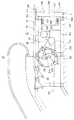
本実施例のエスカレータ10の構造について、図1に基づいて説明する。
(1) Structure of
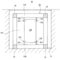
建屋には、エスカレータ10の設置及び搬入のために、エスカレータ10のトラス12よりも若干広い設置空間であるピット11が設けられている。このピット11には、エスカレータ10の本体であるトラス12が設置される。トラス12は、棒状の金属材であるフレーム13,54,58を箱形に組み合わせて形成されている。
The building is provided with a
トラス12の上階側端部にある機械室14には、エスカレータ10を駆動するための駆動装置16が設けられている。この駆動装置16は、駆動モータ18、駆動モータ18の出力軸に接続された減速機20、駆動モータ18と減速機20との間に設けられたブレーキを有している。減速機20の出力軸には、駆動小スプロケット22が取り付けられている。
A
一方、駆動軸24には、不図示の駆動大スプロケットが取り付けられ、前記した駆動小スプロケット22と駆動大スプロケットには、無端の駆動チェーン26が掛け渡されている。駆動軸24の両端には、左右一対の踏段スプロケット28,28が取り付けられている。トラス12の下階側には不図示の左右一対の踏段スプロケットが取り付けられ、上階側の踏段スプロケット28,28との間に無端の踏段チェーン30,30が掛け渡されている。この左右一対の踏段チェーン30,30の間には踏段32が複数取り付けられている。踏段32には、前車輪34と後車輪36とがそれぞれ設けられ、それぞれ異なる不図示のガイドレールに沿って移動自在となっている。
On the other hand, a drive large sprocket (not shown) is attached to the
建屋におけるピット11の後面46の上端部には、段差を設けて水平な支床部42が設けられている。そして、トラス12の後面40の上端部には、逆L字状の支持金具44が突出し、支床部42の上に載置できる。これによって、機械室14があるトラス12の後端部は、ピット11内部に設置できる。この場合に、トラス12の後面40と、ピット11の後面46との間には空間48が形成される。
At the upper end of the
(2)制御装置38の構造、
機械室14には、駆動モータ18、ブレーキ、安全スイッチなどを制御するための制御装置38が設けられている。この制御装置38には、作業者がエスカレータ10を制御、点検するためのコンピュータよりなる制御部、操作スイッチ、表示部などが設けられている。
(2) the structure of the
The
制御装置38は、図1に示すように機械室14の最も奥にある側面(以下、「後面」という)40に前後方向に移動自在に設けられている。後面40は、図5に示すようにトラス12を構成する上フレーム54,下フレーム58、左右フレームによって囲まれた面であって、これらフレーム54,58の間は開口している。制御装置38は、直方体であって、その両側面の上下部にそれぞれボルト50,52が螺合するためのネジ孔が開口している。
As shown in FIG. 1, the
トラス12の後面40の天井部にある上フレーム54からは左右一対の金属製のL字状の取り付け部材56が吊り下げられている。また、トラス12の後面40の底面部にある下フレーム58から上方へ逆L字状の取り付け部材60が立設されている。
A pair of left and right metal L-
逆L字状の取り付け部材56の水平部分には、長孔62が前後方向に貫通し、この長孔62の両端部及び中央部分には円弧状の溝64がそれぞれ開口している。
A
取り付け部材60の水平部分にも同様に、長孔66が前後方向に貫通し、この長孔62の両端部及び中央部分には円弧状の溝68がそれぞれ開口している。
Similarly, a
制御装置38は、図5に示すように、左右一対の取り付け部材56,56及び左右一対の取り付け部材60,60の間にボルト50,52で固定される。以下その固定方法について順番に説明する。
As shown in FIG. 5, the
(4)トラス12の設置時
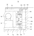
トラス12をピット11に設置する時の制御装置38の固定方法について図2に基づいて説明する。
(4) At the time of installation of the truss 12 A method of fixing the
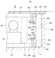
トラス12をピット11に設置する時には、制御装置38を機械室14内部に収納しておく。すなわち、図2に示すように、取り付け部材56,60の長孔62,66の最も左側に制御装置38のネジ孔を合わせ、ボルト50,52によって制御装置38を固定する。
When the
これによって、トラス12を搬送したり、ピット11に設置及び搬入したりする場合に、制御装置38がその作業の邪魔になることがない。
As a result, when the
但し、制御装置38と駆動装置16の間にある空間70は最も狭い空間となっている。
However, the
(5)トラス12の設置後
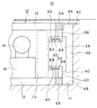
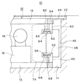
トラス12をピット11に設置した後の制御装置38の固定方法について図3、図4に基づいて説明する。
(5) After Installation of Truss 12 A method for fixing the
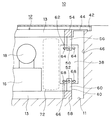
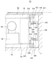
トラス12をピット11に設置した後は、制御装置38をピット11とトラス12の後面40との間の空間48に水平方向(前後方向)に移動させる。すなわち、図3、図4に示すように、ボルト50,52を外し、制御装置38を長孔62,66に沿って水平方向に移動させ、機械室14の後面40から空間48に突出させる。この突出させる量は空間48の幅にもよるが、この空間の奥行きが小さい場合は、図3に示す位置のように長孔62,66の中央部の溝68の位置でボルト50,52を固定する。また、空間48の奥行きがさらに広い場合には、図4に示すように、長孔62,66の最も右側にある64,68の位置でボルト50,52を固定する。
After the
これによって、制御装置16は、従来はデット空間であった空間48に設置することができ、また、図3に示す位置では、駆動装置16との間の空間72が空間70よりも広くなり、また、図4に示す位置では、駆動装置16と制御装置38との間が最も広い空間74となる。したがって、作業者は、空間70よりも広くなった空間72又は空間74で制御装置38を操作できる。
As a result, the
(6)効果
本実施例によれば、トラス12の設置を行う場合には、制御装置38を機械室14内部に収納して作業できるため、制御装置38はその作業に邪魔になることがない。
(6) Effect According to the present embodiment, when the
また、トラス12の設置後には、制御装置16は、従来はデット空間であった空間48に設置でき、機械室14における作業、点検空間が広くなる。
In addition, after the
次に、本発明に係る実施例2のエスカレータ10について図6〜図8に基づいて説明する。
Next, the
本実施例と実施例1の異なる点は、長孔62,66を設ける位置が異なる点にある。本実施例では、長孔62,66を制御装置38の両側面に水平方向(前後方向)にそれぞれ設ける。また、取り付け部材56,60には、それぞれネジ孔を設けておく。
The difference between this embodiment and Embodiment 1 is that the positions where the
実施例1と同様に本実施例でも、トラス12を設置する時は、図6に示すように、制御装置38が機械室14内部に収納するために、長孔62,66の右端部の位置で取り付け部材56,60を合わせ、ボルト50,52で固定する。
Similarly to the first embodiment, in this embodiment, when the
次に、トラス12をピット11に設置した後は、空間48の大きさに合わせて、図7又は図8に示すように、長孔62,66の中央部の溝64,68又は左端部にある溝64,68に取り付け部材56,60を合わせ、ボルト50,52で固定する。
Next, after the
本実施例においても、トラス12を設置する場合には、機械室14内部に制御装置38を収納できる。また、トラス12の設置後には、制御装置16は、従来はデット空間であった空間48に設置でき、機械室14における作業、点検空間が広くなる。
Also in the present embodiment, when the
次に、本発明に係る実施例3のエスカレータ10について図9に基づいて説明する。
Next, the
本実施例と実施例1の異なる点は、トラス12に取り付け部材56,60を設けるのでなく、ピット11の後面46に制御装置38の取り付け部材76を設置する。
The difference between the present embodiment and the first embodiment is that the mounting
トラス12の搬入、設置時には、制御装置38を外しておき、トラス12をピット11に設置した後、ピット11の取り付け部材76を設置し、その後に制御装置38を取り付け部材76に設置する。
When the
本実施例においても、トラス12の設置後は、制御装置16は、従来はデット空間であった空間48に設置することができ、機械室14における作業、点検空間が広くなる。
Also in the present embodiment, after the
上記各実施例では、エスカレータ10で説明したが、これに代えて動く歩道でも本発明の実施形態を適用することができる。
In each of the above-described embodiments, the
上記各実施例では、制御装置38を設置する空間として、トラス12の後面40とピット11の後面46との間の空間48としたが、これに限らずトラス12の左側面又は右側面とピット11の左側面又は右側面の間の空間に制御装置38を設置してもよい。なお、本発明におけるトラスの側面とは、左側面、右側面に加えて後面や前面も含むものとする。
In each of the above embodiments, the space for installing the
上記では本発明の一実施形態を説明したが、この実施形態は、例として提示したものであり、発明の範囲を限定することは意図していない。これら新規な実施形態は、その他の様々な形態で実施されることが可能であり、発明の主旨を逸脱しない範囲で、種々の省略、置き換え、変更を行うことができる。これら実施形態やその変形は、発明の範囲や要旨に含まれるとともに、特許請求の範囲に記載された発明とその均等の範囲に含まれる。 Although one embodiment of the present invention has been described above, this embodiment is presented as an example and is not intended to limit the scope of the invention. These novel embodiments can be implemented in various other forms, and various omissions, replacements, and changes can be made without departing from the spirit of the invention. These embodiments and modifications thereof are included in the scope and gist of the invention, and are included in the invention described in the claims and the equivalents thereof.
10・・・エスカレータ、11・・・ピット、12・・・トラス、14・・・機械室
16・・・駆動装置、38・・・制御装置、40・・・機械室の後面、46・・・ピットの後面、48・・・空間、50・・・ボルト、52・・・ボルト、56・・・取り付け部材、60・・・取り付け部材、62・・・長孔、64・・・溝、66・・・長孔、68・・・溝
DESCRIPTION OF
Claims (5)
前記側面と前記ピットの間の空間に前記制御装置を移動させる移動手段と、
を有することを特徴とする乗客コンベア。 A control device for a passenger conveyor arranged on the side of the truss facing the pit where the truss is arranged;
Moving means for moving the control device to a space between the side surface and the pit;
Passenger conveyor characterized by having.
前記長孔に沿って前記制御装置が移動自在であって、前記長孔を用いて前記制御装置を、前記取り付け部材にボルトで取り付ける、
ことを特徴とする請求項1に記載の乗客コンベア。 The moving means is a long hole opened in a mounting member provided in the frame of the truss;
The control device is movable along the long hole, and the control device is attached to the attachment member with a bolt using the long hole.
The passenger conveyor according to claim 1.
前記長孔に沿って前記制御装置が移動自在であって、前記長孔を用いて前記制御装置を、前記トラスのフレームに設けられた取り付け部材にボルトで取り付ける、
ことを特徴とする請求項2に記載の乗客コンベア。 The moving means is a long hole opened in the control device;
The control device is movable along the long hole, and the control device is bolted to a mounting member provided on a frame of the truss using the long hole.
The passenger conveyor according to claim 2.
ことを特徴とする請求項2又は3に記載の乗客コンベア。 A groove for positioning the control device in stages is opened in the elongated hole.
The passenger conveyor according to claim 2 or 3, characterized in that.
ことを特徴とする乗客コンベア。 A mounting member for installing a control device for a passenger conveyor is provided in the pit in a space between the side surface of the truss facing the pit where the truss is arranged and the pit.
A passenger conveyor characterized by that.
Priority Applications (1)
| Application Number | Priority Date | Filing Date | Title |
|---|---|---|---|
| JP2011004189A JP2012144336A (en) | 2011-01-12 | 2011-01-12 | Passenger conveyor |
Applications Claiming Priority (1)
| Application Number | Priority Date | Filing Date | Title |
|---|---|---|---|
| JP2011004189A JP2012144336A (en) | 2011-01-12 | 2011-01-12 | Passenger conveyor |
Publications (1)
| Publication Number | Publication Date |
|---|---|
| JP2012144336A true JP2012144336A (en) | 2012-08-02 |
Family
ID=46788336
Family Applications (1)
| Application Number | Title | Priority Date | Filing Date |
|---|---|---|---|
| JP2011004189A Pending JP2012144336A (en) | 2011-01-12 | 2011-01-12 | Passenger conveyor |
Country Status (1)
| Country | Link |
|---|---|
| JP (1) | JP2012144336A (en) |
Cited By (2)
| Publication number | Priority date | Publication date | Assignee | Title |
|---|---|---|---|---|
| WO2015037070A1 (en) * | 2013-09-11 | 2015-03-19 | 株式会社日立製作所 | Passenger conveyor equipment |
| CN110775797A (en) * | 2018-07-27 | 2020-02-11 | 奥的斯电梯公司 | Misalignment monitoring in people conveyors |
-
2011
- 2011-01-12 JP JP2011004189A patent/JP2012144336A/en active Pending
Cited By (4)
| Publication number | Priority date | Publication date | Assignee | Title |
|---|---|---|---|---|
| WO2015037070A1 (en) * | 2013-09-11 | 2015-03-19 | 株式会社日立製作所 | Passenger conveyor equipment |
| CN105492364A (en) * | 2013-09-11 | 2016-04-13 | 株式会社日立制作所 | Passenger conveyor equipment |
| JP6037023B2 (en) * | 2013-09-11 | 2016-11-30 | 株式会社日立製作所 | Passenger conveyor equipment |
| CN110775797A (en) * | 2018-07-27 | 2020-02-11 | 奥的斯电梯公司 | Misalignment monitoring in people conveyors |
Similar Documents
| Publication | Publication Date | Title |
|---|---|---|
| WO2017106986A1 (en) | Bidirectional rail conveying apparatus | |
| NO20062421L (en) | Elevator cabin with submersible cabin roof | |
| JP2009184771A (en) | Passenger conveyer and renewal method of the same | |
| JP2008285310A (en) | Passenger conveyer, gap adjustment method, and gap adjuster | |
| JP2012144336A (en) | Passenger conveyor | |
| JP2013249166A (en) | Passenger detecting device of passenger conveyor | |
| CN105492364A (en) | Passenger conveyor equipment | |
| US9950903B2 (en) | Truss construction for a passenger conveyor comprising a single wall profile | |
| CN101376480B (en) | Passenger Conveyor | |
| AR054177A1 (en) | INSTALLATION WITH A SUSTAINING MEDIA FOR THE OPERATION OF AN ELEVATOR CABIN, AND A CORRESPONDING SUBSTANCE MEANS | |
| JP5748329B2 (en) | Renewal method of passenger conveyor | |
| JP5937240B1 (en) | Passenger conveyor | |
| JP7167836B2 (en) | Working step of passenger conveyor and working method using the working step | |
| CN204588414U (en) | A kind of counterweight housing of elevator | |
| JP6370007B1 (en) | Passenger conveyor installation method and passenger conveyor | |
| AR049230A1 (en) | OPERATION FOR AN ELEVATOR INSTALLATION | |
| JPH11165973A (en) | Replacing method of escalator step link and guide rail device therefor | |
| CN106241582B (en) | Passenger conveyors | |
| JP5814454B1 (en) | Escalator | |
| CN101898716A (en) | Drives for passenger conveyors | |
| HK1243988A1 (en) | Passenger transport device | |
| TW200710753A (en) | Computer-assisted method of providing components for lifts, escalators and moving walkways, and corresponding delivery units | |
| EA032528B1 (en) | Passenger transport device | |
| JP6077058B2 (en) | Passenger conveyor | |
| UA119087C2 (en) | Passenger tranport device with auxiliary brake |