JP2012144353A - Substrate conveyance apparatus and substrate conveyance method - Google Patents
Substrate conveyance apparatus and substrate conveyance method Download PDFInfo
- Publication number
- JP2012144353A JP2012144353A JP2011005219A JP2011005219A JP2012144353A JP 2012144353 A JP2012144353 A JP 2012144353A JP 2011005219 A JP2011005219 A JP 2011005219A JP 2011005219 A JP2011005219 A JP 2011005219A JP 2012144353 A JP2012144353 A JP 2012144353A
- Authority
- JP
- Japan
- Prior art keywords
- substrate
- holding
- holding unit
- fixed base
- lifting
- Prior art date
- Legal status (The legal status is an assumption and is not a legal conclusion. Google has not performed a legal analysis and makes no representation as to the accuracy of the status listed.)
- Pending
Links
- 239000000758 substrate Substances 0.000 title claims abstract description 506
- 238000000034 method Methods 0.000 title claims description 23
- 230000007246 mechanism Effects 0.000 claims abstract description 220
- 230000008859 change Effects 0.000 claims description 7
- 230000032258 transport Effects 0.000 description 64
- 210000000078 claw Anatomy 0.000 description 23
- 238000011144 upstream manufacturing Methods 0.000 description 15
- 238000010586 diagram Methods 0.000 description 12
- 238000012423 maintenance Methods 0.000 description 6
- 238000010438 heat treatment Methods 0.000 description 5
- 230000001133 acceleration Effects 0.000 description 3
- 238000001816 cooling Methods 0.000 description 3
- 230000003028 elevating effect Effects 0.000 description 3
- 230000008569 process Effects 0.000 description 3
- 238000009434 installation Methods 0.000 description 2
- 230000005540 biological transmission Effects 0.000 description 1
- 230000000694 effects Effects 0.000 description 1
- 239000011521 glass Substances 0.000 description 1
- 230000020169 heat generation Effects 0.000 description 1
- 239000004973 liquid crystal related substance Substances 0.000 description 1
Images
Landscapes
- Container, Conveyance, Adherence, Positioning, Of Wafer (AREA)
Abstract
Description
本発明は、処理台上の基板を搬送する基板搬送装置及び基板搬送方法に関する。 The present invention relates to a substrate transfer apparatus and a substrate transfer method for transferring a substrate on a processing table.
薄型基板を対象に熱加工処理を行う場合には、複数の処理台に基板を順次搬送する基板搬送装置が用いられる。図7は、従来の基板搬送装置700を示す模式図である。基板搬送装置700は、基板を裁置する裁置台3と、基板を持ち上げ移動させる基板移動機構4とを備える。図7(a)は基板aを搬送する基板搬送装置700を示し、図7(b)は基板aと異なる大きさの基板bを搬送する基板搬送装置700を示す。裁置台3と基板移動機構4とが協働することで、基板aや、基板bを順次搬送し得る。基板移動機構4は基板保持部分40を有している。基板保持部分40は階段形状であるため、階段形状に整合する大きさの基板a及び基板bを、機械部品の段取り替えを行わずに搬送することができる。
When thermal processing is performed on a thin substrate, a substrate transfer device that sequentially transfers the substrate to a plurality of processing stands is used. FIG. 7 is a schematic view showing a conventional
しかしながら、基板保持部分の階段形状は固定されているため階段形状を変更することはできない。従って、基板保持部分40の階段形状に整合しない大きさの基板を搬送する場合には、基板保持部分40を段取り替えするか、基板保持部分40の階段形状を作り変えなければならなかった。特に、裁置台3が加熱装置としても機能する場合には、搬送を停止し、また加熱も停止する必要があるため、段取り替えに伴う処理台の温度の低下や再上昇に伴う時間ロスが大きく、作業効率やエネルギー効率が悪かった。
However, since the staircase shape of the substrate holding portion is fixed, the staircase shape cannot be changed. Therefore, when a substrate having a size that does not match the step shape of the
本発明は、搬送する基板の大きさに応じて基板保持機構の大きさを調整し得る基板搬送装置を提供することを目的とする。 An object of the present invention is to provide a substrate transport apparatus that can adjust the size of a substrate holding mechanism in accordance with the size of a substrate to be transported.
上記課題を解決するために、本発明の基板搬送装置の特徴的な構成は、処理台上の基板を搬送する基板搬送装置であって、処理台から基板を持上げる基板持上げ機構と、基板の大きさに合わせて開閉し、持上げた基板を保持する基板保持機構とを備える。 In order to solve the above problems, a characteristic configuration of a substrate transfer apparatus according to the present invention is a substrate transfer apparatus that transfers a substrate on a processing table, a substrate lifting mechanism that lifts the substrate from the processing table, A substrate holding mechanism that opens and closes in accordance with the size and holds the lifted substrate.
本発明の基板搬送装置によれば、基板保持機構の大きさは固定されておらず、搬送する基板の大きさに応じて基板保持機構の大きさを調整し得る。その結果、基板保持機構の部品の段取り替えを行うことなく、様々な大きさの基板搬送に対応し得る基板搬送装置を実現することができる。 According to the substrate transfer apparatus of the present invention, the size of the substrate holding mechanism is not fixed, and the size of the substrate holding mechanism can be adjusted according to the size of the substrate to be transferred. As a result, it is possible to realize a substrate transfer apparatus that can handle transfer of various sizes of substrates without changing the components of the substrate holding mechanism.
本発明に係る基板搬送装置の好適な実施形態によれば、処理台は、第1固定台と第2固定台とを含み、基板保持機構は、第1固定台と第2固定台との間を移動し、基板持上げ機構と基板保持機構との協働により、基板を第1固定台から第2固定台に搬送する。 According to a preferred embodiment of the substrate transfer apparatus of the present invention, the processing table includes a first fixed table and a second fixed table, and the substrate holding mechanism is between the first fixed table and the second fixed table. And the substrate is transported from the first fixing base to the second fixing base by the cooperation of the substrate lifting mechanism and the substrate holding mechanism.
本発明に係る基板搬送装置の好適な実施形態によれば、基板保持機構は、基板の一方を保持する第1保持部と、基板の一方とは異なる他の一方を保持する第2保持部とを備え、第1保持部と第2保持部とが基板の搬送方向に沿って移動し、第1保持部と第2保持部との距離を変更する。従って、基板保持機構は基板の搬送方向に沿って開閉する。その結果、基板の搬送方向に対して直行方向に開閉する機構を備えた基板搬送装置と比べて、設置面積を小さくすることができる。 According to a preferred embodiment of the substrate transfer apparatus of the present invention, the substrate holding mechanism includes a first holding unit that holds one of the substrates, and a second holding unit that holds the other one different from one of the substrates. The first holding unit and the second holding unit move along the substrate transport direction, and the distance between the first holding unit and the second holding unit is changed. Accordingly, the substrate holding mechanism opens and closes along the substrate transport direction. As a result, the installation area can be reduced as compared with a substrate transfer apparatus having a mechanism that opens and closes in a direction perpendicular to the substrate transfer direction.
本発明に係る基板搬送装置の好適な実施形態によれば、基板の搬送方向に沿って設けられたガイドレールを更に備え、第1保持部と第2保持部とは、基板の大きさに合わせて開閉するためにガイドレール上を移動し、さらに第1保持部と第2保持部とは、基板を第1固定台から第2固定台に搬送するためにガイドレール上を移動する。従って、基板の大きさに合わせて開閉するための移動と、基板を第1固定台から第2固定台に搬送するための移動とを別々のガイドレール上で行う場合と比べてガイドレールの本数を節約することができ、また基板搬送装置コンパクト化することができる。 According to a preferred embodiment of the substrate transfer apparatus according to the present invention, the substrate transfer device further includes guide rails provided along the substrate transfer direction, and the first holding unit and the second holding unit are adapted to the size of the substrate. The first holding part and the second holding part move on the guide rail to transport the substrate from the first fixed base to the second fixed base. Therefore, the number of guide rails compared to the case where the movement for opening and closing according to the size of the board and the movement for transporting the board from the first fixed base to the second fixed base are performed on separate guide rails. Can be saved, and the substrate transfer apparatus can be made compact.
本発明に係る基板搬送装置の好適な実施形態によれば、基板保持機構は、回転駆動機構を更に備え、第1保持部と第2保持部とは回転駆動機構に係止され、回転駆動機構の回転によって、第1保持部と第2保持部とが遠近移動する。従って、回転駆動機構の回転によって、基板保持機構を開閉することができる。その結果、基板保持機構の開閉動作を単純な構造で実現できる。 According to a preferred embodiment of the substrate transport apparatus of the present invention, the substrate holding mechanism further includes a rotation driving mechanism, and the first holding unit and the second holding unit are locked to the rotation driving mechanism, and the rotation driving mechanism. The first holding part and the second holding part move far and near by the rotation of. Therefore, the substrate holding mechanism can be opened and closed by the rotation of the rotation driving mechanism. As a result, the opening / closing operation of the substrate holding mechanism can be realized with a simple structure.
本発明に係る基板搬送装置の好適な実施形態によれば、第1固定台と第2固定台とは、基板の全面を保持する。従って、基板の全面を均一処理することができる。特に固定台が加熱台又は冷却台として機能する場合には、基板の全面を均一に加熱又は冷却することができる。 According to a preferred embodiment of the substrate transfer apparatus according to the present invention, the first fixed base and the second fixed base hold the entire surface of the substrate. Therefore, the entire surface of the substrate can be uniformly processed. In particular, when the fixed table functions as a heating table or a cooling table, the entire surface of the substrate can be uniformly heated or cooled.
本発明に係る基板搬送装置の好適な実施形態によれば、第1固定台は、第1温度で発熱する第1発熱部を備え、第2固定台は、第2温度で発熱する第2発熱部を備える。従って、第1温度と第2温度とが同じ場合でも、異なる場合でも、基板の搬送中に様々な温度で基板を熱処理することができる。 According to a preferred embodiment of the substrate transfer apparatus of the present invention, the first fixed base includes the first heat generating part that generates heat at the first temperature, and the second fixed base generates the second heat generated at the second temperature. A part. Therefore, regardless of whether the first temperature and the second temperature are the same or different, the substrate can be heat-treated at various temperatures during the transfer of the substrate.
本発明に係る基板搬送方法の好適な実施形態によれば、処理台上の基板を搬送する基板搬送方法であって、処理台から基板を持上げる基板持上げ工程と、基板の大きさに合わせて開閉し、持上げた基板を保持する基板保持工程とを包含する。 According to a preferred embodiment of the substrate transport method according to the present invention, there is provided a substrate transport method for transporting a substrate on a processing table, in accordance with a substrate lifting process for lifting the substrate from the processing table and the size of the substrate. A substrate holding step of opening and closing and holding the lifted substrate.
本発明に係る基板搬送方法の好適な実施形態によれば、処理台から基板を持上げる基板持上げ機構と、基板の大きさに応じて開閉し、持上げた基板を保持する基板保持機構とを備えた基板搬送装置において、処理台は、第1固定台と第2固定台とを含み、基板保持工程において、基板保持機構が第1固定台と第2固定台との間を移動する工程を実行し、基板持上げ工程と基板保持工程とにより、基板を第1固定台から第2固定台に搬送する工程を実行する。 According to a preferred embodiment of the substrate transport method according to the present invention, a substrate lifting mechanism that lifts the substrate from the processing table, and a substrate holding mechanism that opens and closes according to the size of the substrate and holds the lifted substrate are provided. In the substrate transfer apparatus, the processing table includes a first fixing table and a second fixing table, and in the substrate holding process, the substrate holding mechanism performs a step of moving between the first fixing table and the second fixing table. Then, a step of transporting the substrate from the first fixed base to the second fixed base is executed by the substrate lifting step and the substrate holding step.
本発明に係る基板搬送方法の好適な実施形態によれば、基板保持機構は、基板の一方を保持する第1保持部と、基板の一方とは異なる他の一方を保持する第2保持部と、第1保持部と第2保持部とが係止されている回転駆動機構とを備え、基板保持工程において、回転駆動機構の回転よって、第1保持部と第2保持部とが遠近移動する工程を実行する。 According to a preferred embodiment of the substrate transport method of the present invention, the substrate holding mechanism includes a first holding unit that holds one of the substrates, and a second holding unit that holds the other one different from one of the substrates. And a rotation driving mechanism in which the first holding unit and the second holding unit are locked. In the substrate holding step, the first holding unit and the second holding unit move in the near and far directions by the rotation of the rotation driving mechanism. Execute the process.
本発明に係る基板搬送方法の好適な実施形態によれば、基板持上げ機構は、第1基板持上げ機構と第2基板持上げ機構とを含み、第1基板持上げ機構によって第1固定台から基板を持上げる工程と、基板の大きさに合わせて第1保持部と第2保持部との距離を縮め、持上げた基板を基板保持機構によって保持する工程と、第1基板持上げ機構を降ろす工程と、基板保持機構を第1固定台から第2固定台に移動する工程と、第2基板持上げ機構によって基板保持機構から基板を持上げる工程と、第1保持部と第2保持部との距離を伸ばし、持上げた基板を基板保持機構から離す工程と、第2基板持上げ機構を降ろし、基板を第2固定台に乗せる工程と、基板保持機構を第2固定台から第1固定台に移動する工程とを包含する。 According to a preferred embodiment of the substrate transport method of the present invention, the substrate lifting mechanism includes a first substrate lifting mechanism and a second substrate lifting mechanism, and the first substrate lifting mechanism holds the substrate from the first fixed base. A step of raising, a step of reducing the distance between the first holding unit and the second holding unit in accordance with the size of the substrate, holding the lifted substrate by the substrate holding mechanism, a step of lowering the first substrate lifting mechanism, and a substrate A step of moving the holding mechanism from the first fixing base to the second fixing base, a step of lifting the substrate from the substrate holding mechanism by the second substrate lifting mechanism, and extending a distance between the first holding portion and the second holding portion, Separating the lifted substrate from the substrate holding mechanism, lowering the second substrate lifting mechanism, placing the substrate on the second fixing base, and moving the substrate holding mechanism from the second fixing base to the first fixing base. Include.
図1〜図6を参照して、本発明の基板搬送装置及び基板搬送方法に関する実施形態を説明する。本発明は、以下に説明する実施形態や図面に記載される構成に限定されることを意図せず、当該構成と均等な構成も含む。 With reference to FIGS. 1-6, embodiment regarding the board | substrate conveyance apparatus and board | substrate conveyance method of this invention is described. The present invention is not intended to be limited to the configurations described in the embodiments and drawings described below, and includes configurations equivalent to those configurations.
[基板搬送装置]
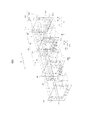
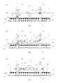
図1は、本発明に係る基板搬送装置100を示す模式図である。基板搬送装置100は、処理台A上の基板Bを搬送する。基板搬送装置100は、第1基板持上げ機構110と基板保持機構120とを備える。
[Substrate transfer device]
FIG. 1 is a schematic view showing a
第1基板持上げ機構110は、処理台Aから基板Bを持上げる。基板保持機構120は、基板Bの大きさに合わせて開閉し、第1基板持上げ機構110によって持上げられた基板Bを保持する。処理台Aは、第1固定台A1と第2固定台A2とを含む。基板保持機構120は、第1固定台A1と第2固定台A2との間を移動する可動ユニットである。第1基板持上げ機構110と基板保持機構120との協働により、基板Bを第1固定台A1から第2固定台A2に搬送する。その結果、基板Bは方向αに沿って搬送される。
The first
基板搬送装置100は第2基板持上げ機構130を更に備える。第1基板持上げ機構110及び第2基板持上げ機構130は、基台に固定されている固定ユニットである。第1基板持上げ機構110は、第1昇降手段112と第1支持ピン群114とを備える。第2基板持上げ機構130は、第2昇降手段132と第2支持ピン群134とを備える。第1基板持上げ機構110及び第2基板持上げ機構130の詳細は、図2を参照して後述する。
The
基板保持機構120は、第1基板B1の一方(基板Bの搬送方向αに対して上流側)を保持する第1保持部121と、第1基板B1の一方とは異なる他の一方(基板Bの搬送方向αに対して下流側)を保持する第2保持部123と、第1連結部材122と、第2連結部材124とを備える。第1保持部121は基板Bの搬送方向αに対して上流側の保持部であり、第2保持部123は基板Bの搬送方向αに対して下流側の保持部である。第1保持部121と第2保持部123とが基板の搬送方向αに沿って移動し、第1保持部121と第2保持部123との距離を変更する。
The
第1連結部材122は、複数の上流側保持部を連結部a1、連結部a2及び連結部a3で連結する。第2連結部材124は、複数の下流側保持部を連結部で連結する。具体的には、第2連結部材124は、第2保持部123を連結部b1で連結し、保持部143を連結部b2で連結し、保持部163を連結部b3で連結している。
The
第1保持部121は、第1スライダ121aと第2スライダ121bと保持アーム121cと第1保持爪群121dとを備える。第1スライダ121aと第2スライダ121bとは、基板Bの搬送方向αに沿った第1保持部121の移動をガイドする。
The
第1保持爪群121dは、保持アーム121cに設けられている。第1保持爪群121dは第1基板B1の一方(基板Bの搬送方向αに対して上流側)を直接保持する。第1保持爪群121dは3つの保持爪を含み、3つの保持爪は、第1基板B1の搬送方向αに直行するように並ぶ。
The first holding claw group 121d is provided on the holding
複数の上流側保持部及び複数の下流側保持部(第2保持部123、保持部143、保持部163)は、第1保持部121と同様の構成を有する。例えば、第2保持部123は、第2保持爪群123dを備える。第2保持爪群123dは、第2保持部123が備える保持アームに設けられている。第2保持爪群123dは第1基板B1の一方(基板Bの搬送方向αに対して下流側)を直接保持する。第2保持爪群123dは3つの保持爪を含み、3つの保持爪は、第1基板B1の搬送方向αに直行するように並ぶ。
The plurality of upstream holding units and the plurality of downstream holding units (second holding
第1保持爪群121dと第2保持爪群123dとは、互いに向かい合うように配置されている。第1保持部121と第2保持部123とは第1基板B1の大きさに合わせて移動し、第1保持爪群121dと第2保持爪群123dとによって第1基板B1を保持する。
The first holding claw group 121d and the second holding claw group 123d are arranged so as to face each other. The
基板搬送装置100はガイドレール170を更に備える。ガイドレール170は第1ガイドレール170aと第2ガイドレール170bとを含む。第1ガイドレール170aと第2ガイドレール170bとは基板の搬送方向αに沿って互いに平行に基台C(図示せず。)の上に設置されている。第1ガイドレール170aには第1スライダ121aが、第2ガイドレール170bには第2スライダ121bが取り付けてある。
The
基板搬送装置100は、ウォーキングビーム式基板搬送装置である。ウォーキングビーム式によれば、処理台A(第1固定台A1及び第2固定台A2)を固定し、基板保持機構120を基板Bの搬送方向に沿って第1固定台A1と第2固定台A2との間で往復移動させることで、第1基板持上げ機構110上の基板Bを1ストローク分ずつ移動させ得る。なお、1ストロークは第1固定台A1の中央から第2固定台A2の中央までの距離に対応する。例えば、基板搬送装置100によれば、第1保持部121と第2保持部123とは、基板Bを第1固定台A1から第2固定台A2に1ストローク分搬送するためにガイドレール170上を移動する。
The
基板搬送装置100では、基板保持機構120が基板Bの大きさに合わせて開閉するので、大きさの異なる基板を搬送する際に、機械部品の段取り替えや作り変えを行う必要がない。保持爪の数や配置、さらに支持ピンの数や配置を適切に選択することで、無段階の大きさの基板を取り扱い得る。また、保持爪の形状がL字形であれば、搬送による基板の脱落や基板の位置ずれを防止することができる。その結果、加減速を大きくして搬送時間を短縮した動作が可能となる。
In the
本発明の基板搬送装置100では、基板Bの大きさは、α方向の長さ(縦の長さ)が1200mmであり、横の長さが2200mmであるが、基板保持機構120が基板Bの大きさに合わせて開閉するので、大きさの異なる基板(縦1500mm、横1700mmの基板や縦1400mm、横2400mmの基板)を搬送する際でも、基板搬送装置100の段取り替えや作り変えを行う必要がない。
In the
本発明の基板搬送装置100は処理台Aから基板Bを持上げる第1基板持上げ機構110と、基板Bの大きさに合わせて開閉し、持上げた基板Bを保持する基板保持機構120とを備える。従って、基板保持機構120の大きさは固定されておらず、搬送する基板Bの大きさに応じて基板保持機構120の大きさを調整し得る。その結果、基板保持機構120の部品の段取り替えを行うことなく、様々な大きさの基板搬送に対応し得る基板搬送装置100を実現することができる。段取り替えなく取り扱え得る基板の大きさが無段階となる。
The
さらに、基板搬送装置100の好適な特徴構成によれば、基板保持機構100は、基板Bの一方を保持する第1保持部121と、基板Bの一方とは異なる他の一方を保持する第2保持部123とを備え、第1保持部121と第2保持部123とが基板Bの搬送方向αに沿って移動し、第1保持部121と第2保持部123との距離を変更する。従って、基板保持機構100は基板Bの搬送方向αに沿って開閉する。その結果、基板Bの搬送方向αに対して直行方向に開閉する機構を備えた基板搬送装置と比べて、設置面積を小さくすることができる。
Furthermore, according to a preferred characteristic configuration of the
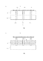
図2は、第1基板持上げ機構110を示す模式図である。図2(a)は、第1固定台A1に第1基板B1を降ろした第1基板持上げ機構110を示し、図2(b)は第1固定台A1から第1基板B1を持上げた第1基板持上げ機構110を示す。図1を参照して説明したように、第1固定台A1は基台(図示せず)に固定されている。第1固定台A1は、所定間隔で複数の貫通孔(貫通孔A1a、貫通孔A1b、貫通孔A1c)を有す。
FIG. 2 is a schematic diagram showing the first
第1基板持上げ機構110は、第1昇降手段112と第1支持ピン群114とを備える。第1支持ピン群114は支持ピン114a、支持ピン114b及び支持ピン114cを含む。支持ピン114aは貫通孔A1aに、支持ピン114bは貫通孔A1bに、支持ピン114cは貫通孔A1cに、第1固定台A1の載置面から突出しないように第1昇降手段112側から挿入されている。
The first
第1支持ピン群114は第1昇降手段112に連結されている。第1昇降手段112は、第1支持ピン群114が第1固定台A1に内在する状態から第1支持ピン群114が第1固定台A1から突出する状態に変更させるために、第1支持ピン群114をβ方向に沿って往復移動させる。第1昇降手段112が第1支持ピン群114を上げることで、第1基板持上げ機構110は第1固定台A1から第1基板B1を持ち上げる。第1昇降手段112が第1支持ピン群114を下げることで第1基板持上げ機構110は第1固定台A1に第1基板B1を降ろす。
The first
なお、第2基板持上げ機構130も第1基板持上げ機構110と同様の構成を有し、同様の作用効果を奏する。具体的には、第2基板持上げ機構130は、第2昇降手段132と第2支持ピン群134とを備える。第2昇降手段132が第2支持ピン群134を上げることで、第2基板持上げ機構130は第2固定台A2から第2基板B2を持ち上げる。第2昇降手段132が第2支持ピン群134を下げることで、第2基板持上げ機構130は第2固定台A2に第2基板B2を降ろす。
The second
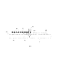
図3は、基板保持機構120の駆動機構200を示す模式図である。駆動機構200には、基板保持機構120(図示せず)が連結されており、駆動機構200の駆動によって基板保持機構120が移動する。基板保持機構120と駆動機構200とは、基板Bの搬送方向αに設けられたガイドレール上を移動する。
FIG. 3 is a schematic diagram showing the
駆動機構200は、支持ベース210と、スライダ220と、スライダ230と、支持ベース210に固定された回転駆動部240と、回転駆動部240に取り付けられたピニオンギア250と、基台Cに固定されたラック260とを備える。スライダ220とスライダ230とは、ガイドレール170に取り付けられている。回転駆動部240からの駆動力がピニオンギア250に伝わり、ピニオンギア250のδ方向に沿った回転によって駆動機構200がガイドレール170上を移動する。
The
基板保持機構120と駆動機構200とは共にガイドレール170に設置されている。従って、基板保持機構120と駆動機構200とを別々のガイドレールに設置する場合と比べてガイドレールの本数を節約することができ、更に基板搬送装置100をコンパクトにすることができる。
The
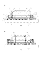
図4は、第1保持部121及び第2保持部123の第1回転駆動機構300を示す模式図である。図4(a)は第1保持部121と第2保持部123とが離れている状態(開状態)を示し、図4(b)は第1保持部121と第2保持部123とが近づいている状態(閉状態)を示す。第1保持部121と第2保持部123とは第1回転駆動機構300に連結され、第1回転駆動機構300の回転方向の切り替えによって、第1保持部121と第2保持部123とがガイドレール170上を遠近移動(開閉移動)する。
FIG. 4 is a schematic diagram illustrating the first
第1回転駆動機構300は、支持ベース210に固定された第1固定手段301と、第1固定手段301に固定された第1タイミングプーリ302と、支持ベース210に固定された第2固定手段303と、第2固定手段303に固定された第2タイミングプーリ304と、第1回転手段305と、タイミングベルト306とを備える。第1保持部121が連結部a1でタイミングベルト306に連結されている。第2保持部123が連結部b1でタイミングベルト306に連結されている。
The first
第1タイミングプーリ302と第2タイミングプーリ304とタイミングベルト306と第1回転手段305とによって、基板保持機構120(第1保持部121及び第2保持部123)に対する第1回転駆動機構300の駆動・伝達機能が生じる。第1回転手段305は第1タイミングプーリ302に連結されている。第1回転手段305の回転方向の切り替えによって、第1保持部121と第2保持部123とが互いに逆方向へ移動する。
Driving the first
図4(a)に示すように、第1タイミングプーリ302がε1方向(時計回り)に回転することで第1保持部121はα1方向(基板Bの搬送方向αに対して上流方向)に移動し、第2保持部123はα2方向(基板Bの搬送方向αに対して下流方向)に移動する。第1保持部121と第2保持部123とが離れる方向に移動することで、基板保持機構120は開状態になる。図4(b)に示すように、第1タイミングプーリ302がε2方向(反時計回り)に回転することで第1保持部121はα2方向(基板Bの搬送方向αに対して下流方向)に移動し、第2保持部123はα1方向(基板Bの搬送方向αに対して上流方向)に移動する。第1保持部121と第2保持部123とが近づく方向に移動することで、基板保持機構120は閉状態になる。
As shown in FIG. 4A, when the
基板保持機構120の開閉距離(例えば、第1保持部121と第2保持部123との距離)は、第1回転駆動機構300の回転の程度に対応する。従って、搬送する基板の大きさに合うよう、予め第1回転駆動機構300の回転の程度を設定しておくことで、種々の大きさの基板搬送が可能な基板搬送装置100を実現し得る。例えば、基板B(大きさx)、基板Y(大きさy)、基板Z(大きさz)の各々の大きさに合わせて、予め第1回転駆動機構300の回転の程度(例えば、基板Bに対してはレベルA、基板Yに対してはレベルB、基板Zに対してはレベルC)を設定し、搬送する基板の大きさに合わせてレベルを変更する。例えば、複数の基板Bを搬送する時には、第1回転駆動機構300の回転の程度をレベルAに設定する。複数の基板Bの搬送が終わり、複数の基板Yを搬送する時には、第1回転駆動機構300の回転の程度をレベルBに設定する。さらに複数の基板Yの搬送が終わって、複数の基板Zを搬送する時には、第1回転駆動機構300の回転の程度をレベルCに設定する。その結果、搬送する基板の大きさに合うよう基板保持機構120が開閉し、基板搬送装置100の段取り替えや作り変えの手間を省くことができる。
The opening / closing distance of the substrate holding mechanism 120 (for example, the distance between the
本発明の基板搬送装置100の好適な特徴構成によれば、基板Bの搬送方向に沿って設けられたガイドレール170を更に備え、第1保持部121と第2保持部123とは、基板Bの大きさに合わせて開閉するためにガイドレール170上を移動し、さらに第1保持部121と第2保持部123とは、基板Bを第1固定台A1から第2固定台A2に搬送するためにガイドレール170上を移動する。従って、基板Bの大きさに合わせて開閉するための移動と、基板Bを第1固定台A1から第2固定台A2に搬送するための移動とを別々のガイドレール上で行う場合と比べてガイドレールの本数を節約することができ、また基板搬送装置100をコンパクトにすることができる。
According to a preferred characteristic configuration of the
本発明の基板搬送装置100の好適な特徴構成によれば、基板保持機構120は、第1回転駆動機構300を更に備え、第1保持部121と第2保持部123とは第1回転駆動機構300に係止され、第1回転駆動機構300の回転によって、第1保持部121と第2保持部123とが遠近移動する。従って、第1回転駆動機構300の回転によって、基板保持機構120を開閉することができる。その結果、基板保持機構120の開閉動作を単純な構造で実現できる。
According to a preferred characteristic configuration of the
[基板搬送方法]
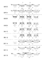
図5は、基板搬送装置100の基板搬送手順を示す模式図である。基板搬送装置100によって本発明の基板搬送方法が実行される。図1から図5を参照して、基板搬送装置100の基板搬送手順であるステップS602〜ステップS618を説明する。
[Substrate transport method]
FIG. 5 is a schematic diagram illustrating a substrate transfer procedure of the
ステップS602:第1固定台A1は第1基板B1を保持し、第2固定台A2は第2基板B2を保持している。第1支持ピン群114は降下しており第1基板B1を支持しておらず、第2支持ピン群134は降下しており第2基板B2を支持していない。基板保持機構120は開状態である。
Step S602: The first fixing base A1 holds the first substrate B1, and the second fixing base A2 holds the second substrate B2. The first
ステップS604:第1支持ピン群114は上昇し、第1固定台A1から第1基板B1を持上げる。第2支持ピン群134は上昇し、第2固定台A2から第2基板B2を持上げる。第1支持ピン群114は第1基板B1を支持し、第2支持ピン群134は第2基板B2を支持する。即ち、第1基板持上げ機構110によって第1固定台A1から第1基板B1を持上げ、第2基板持上げ機構130によって第2固定台A2から第2基板B2を持上げる。第1基板B1は第1固定台A1から150mmの高さまで持上げられ、第2基板B2は第2固定台A2から150mmの高さまで持上げられる。
Step S604: The first
ステップS606:第1保持部121と第2保持部123とは第1基板B1に向かって互いに近づく方向にガイドレール170上を移動する。即ち、第1基板B1の大きさに合わせて第1保持部121と第2保持部123との距離を縮める。基板保持機構120は閉状態である。
Step S606: The
ステップS608:基板保持機構120によって第1基板B1、第2基板B2を持ち上げた状態で第1基板持上げ機構110と第2基板持上げ機構130を降下(即ち、第1支持ピン群114と第2支持ピン群134とを降下)させる。基板保持機構120は第1基板B1及び第2基板B2を保持する。
Step S608: The first
ステップS610:基板保持機構120(第1保持部121と第2保持部123)によって第1基板B1を持ち上げた状態で、基板保持機構120は第1固定台A1から第2固定台A2に500mm/secの速さで1ストロークだけ下流側にガイドレール170上を移動する。1ストロークは第1固定台A1の中央から第2固定台A2の中央までの距離(2400mm)である。
Step S610: In a state where the first substrate B1 is lifted by the substrate holding mechanism 120 (the
ステップS612:第1基板持上げ機構110と第2基板持上げ機構130とによって基板保持機構120から基板を持ち上げる。即ち、第1支持ピン群114が上昇して第1固定台A1から突出し、搬送されてきた次の基板を支持する。第2支持ピン群134が上昇して第2固定台A2から突出し、第1基板B1を支持する。
Step S612: The substrate is lifted from the
ステップS614:第1保持部121と第2保持部123とは第1基板B1から離れる方向にガイドレール170上を移動する。即ち、基板保持機構120から基板Bを持ち上げた状態で第1保持部121と第2保持部123との距離を伸ばし、持上げた基板から基板保持機構120を離す。基板保持機構120は開状態になる。
Step S614: The
ステップS616:第1基板持上げ機構110を降ろし、第1支持ピン群114が支持していた基板を第1固定台A1に乗せる。第1支持ピン群114が下降して第1固定台A1に内在した状態になることで、支持していた基板は第1固定台A1に保持される。第2基板持上げ機構130を降ろし、第1基板B1を第2固定台A2に乗せる。第2支持ピン群134が下降して第2固定台A2に内在した状態になることで、第1基板B1は第2固定台A2に保持される。
Step S616: The first
ステップS618:基板保持機構120(第1保持部121と第2保持部123)は第2固定台A2から第1固定台A1にガイドレール170上を移動する。基板保持機構120が1ストロークだけ上流側に移動することで、基板保持機構120は開始時の位置に戻る。
Step S618: The substrate holding mechanism 120 (the
以上、図5を参照して説明したように、基板搬送装置100によってステップS604〜ステップS610を実行することで、基板保持機構120は下流方向に移動し、第1基板B1を第1固定台A1から第2固定台A2に搬送し得る。基板搬送装置100によってステップS612〜ステップS618を実行することで、基板保持機構120は第1基板B1を第2固定台A2に降ろし、基板保持機構120は上流方向に移動する。
As described above with reference to FIG. 5, by performing Steps S604 to S610 by the
[回転駆動機構]
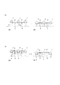
図6は、第1回転駆動機構300の他の例を示す模式図である。図6(a)は、第2回転駆動機構310を示す。基板搬送装置100は第1回転駆動機構300に換えて第2回転駆動機構310を備え得る。第2回転駆動機構310は、支持ベース210に固定された第3固定手段311と、第3固定手段311に固定された第2回転手段312とを備える。第1保持部121が連結部a1で第1連結部材122に連結されている。第2保持部123が連結部b1で第2連結部材124に連結されている。第1連結部材122と第2連結部材124とは第2回転手段312にスライド可能に係止されている。具体的には、第1連結部材122と第2連結部材124とは第2回転手段312に歯車で係止され、第2回転手段312の回転方向の切り替えによって、第1保持部121と第2保持部123とが互いに逆方向へスライドする。
[Rotation drive mechanism]
FIG. 6 is a schematic diagram illustrating another example of the first
例えば、第2回転手段312がε1方向(時計回り)に回転することで第1保持部121はα1方向(基板Bの搬送方向αに対して上流方向)に移動し、第2保持部123はα2方向(基板Bの搬送方向αに対して下流方向)に移動する。第1保持部121と第2保持部123とが離れる方向に移動することで、基板保持機構120は開状態になる。例えば、第2回転手段312がε1方向とは逆方向(反時計回り)に回転することで第1保持部121はα2方向(基板Bの搬送方向αに対して下流方向)に移動し、第2保持部123はα1方向(基板Bの搬送方向αに対して上流方向)に移動する。第1保持部121と第2保持部123とが近づく方向に移動することで、基板保持機構120は閉状態になる。
For example, when the second
図6(b)は、第3回転駆動機構320を示す。基板搬送装置100は第1回転駆動機構300に換えて第3回転駆動機構320を備え得る。第3回転駆動機構320は、支持ベース210に固定された第4固定手段321と、第4固定手段321に固定された第3回転手段322と、第1保持部121に固定された第1連結軸323と、第2保持部123に固定された第2連結軸324とを備える。更に第1保持部121が連結部a1で第1連結部材122に連結されている。また第2保持部123が連結部b1で第2連結部材124に連結されている。
FIG. 6B shows the third
第3回転手段322と第1連結軸323とはボルトとナットの関係にある。第3回転手段322がσ1方向に回転することで第1連結軸323が伸びるように、第3回転手段322と第1連結軸323とには互いに噛み合う溝が掘ってある。第3回転手段322と第2連結軸324とはボルトとナットの関係にある。第3回転手段322がσ1方向に回転することで第2連結軸324が伸びるように、第3回転手段322と第2連結軸324とには互いに噛み合う溝が掘ってある。具体的には、第1連結軸323と第2連結軸324とは第3回転手段322に噛み合うように係止されており、第3回転手段322の回転方向の切り替えによって、第1保持部121と第2保持部123とが互いに逆方向へスライドする。
The third
例えば、第3回転手段322がσ1方向に回転することで第1連結軸323が伸び、第1保持部121はα1方向(基板Bの搬送方向αに対して上流方向)に移動する。同様に第3回転手段322がσ1方向に回転することで第2連結軸324が伸び、第2保持部123はα2方向(基板Bの搬送方向αに対して下流方向)に移動する。第1保持部121と第2保持部123とが離れる方向に移動することで、基板保持機構120は開状態になる。第3回転手段322がσ1方向とは逆方向に回転することで第1連結軸323が縮み、第1保持部121はα2方向(基板Bの搬送方向αに対して下流方向)に移動する。同様に第3回転手段322がσ1方向とは逆方向に回転することで第2連結軸324が縮み、第2保持部123はα1方向(基板Bの搬送方向αに対して上流方向)に移動する。第1保持部121と第2保持部123とが近づく方向に移動することで、基板保持機構120は閉状態になる。
For example, when the third
図6(c)は、第4回転駆動機構330を示す。基板搬送装置100は第1回転駆動機構300に換えて第4回転駆動機構330を備え得る。第4回転駆動機構330は、第5固定手段331と、第5固定手段331に固定された第4回転手段332と、第1保持部121に固定された第1ナット333と、第2保持部123に固定された第2ナット334とを備える。更に第4回転駆動機構330は、第1回転支持部材335と、第2回転支持部材336と、ネジ軸337とを備える。第5固定手段331と第1回転支持部材335と第2回転支持部材336とは支持ベース210に固定されている。
FIG. 6C shows the fourth
第1回転支持部材335と第2回転支持部材336とはネジ軸337を支持している。また、ネジ軸337は、第1ナット333と第2ナット334とを介して第4回転手段332に固定されている。第4回転手段332がσ1方向に回転することで第1保持部121と第2保持部123とが反対方向に移動するように、第1ナット333と第2ナット334とネジ軸337とには互いに噛み合う溝が掘ってある。具体的には、ネジ軸337の両側(第1回転支持部材335側と第2回転支持部材336側)には互いに逆方向(逆ネジの関係)に溝が掘ってある。従って、第1保持部121と第2保持部123とが互いに逆方向へスライドする。
The first
例えば、第4回転手段332がσ1方向に回転することで、第1保持部121はα1方向(基板Bの搬送方向αに対して上流方向)に移動する。同様に第4回転手段332がσ1方向に回転することで第2保持部123はα2方向(基板Bの搬送方向αに対して下流方向)に移動する。第1保持部121と第2保持部123とが離れる方向に移動することで、基板保持機構120は開状態になる。また、第4回転手段332がσ1方向とは逆方向に回転することで第1保持部121はα2方向(基板Bの搬送方向αに対して下流方向)に移動する。第4回転手段332がσ1方向とは逆方向に回転することで第2保持部123はα1方向(基板Bの搬送方向αに対して上流方向)に移動する。第1保持部121と第2保持部123とが近づく方向に移動することで、基板保持機構120は閉状態になる。
For example, when the
なお、回転駆動機構の構成は、第1回転駆動機構300、第2回転駆動機構310、第3回転駆動機構320、第4回転駆動機構330に限定されない。第1保持部121と第2保持部123とが回転手段に係止され、回転手段の回転によって第1保持部121と第2保持部123とが遠近移動する限りは、回転駆動機構の構成は任意である。
The configuration of the rotation drive mechanism is not limited to the first
以上、図1から図6を参照して、本発明の基板搬送装置と基板搬送方法とを説明した。本発明の基板搬送装置および基板搬送方法によれば、基板保持機構の大きさは固定されておらず、搬送する基板の大きさに応じて基板保持機構の大きさや基板保持機構の開閉幅を調整し得る。その結果、基板保持機構の部品の段取り替えを行うことなく、様々な大きさの基板搬送に対応し得る基板搬送装置を実現することができる。 The substrate transport apparatus and the substrate transport method of the present invention have been described above with reference to FIGS. According to the substrate transfer apparatus and the substrate transfer method of the present invention, the size of the substrate holding mechanism is not fixed, and the size of the substrate holding mechanism and the opening / closing width of the substrate holding mechanism are adjusted according to the size of the substrate to be transferred. Can do. As a result, it is possible to realize a substrate transfer apparatus that can handle transfer of various sizes of substrates without changing the components of the substrate holding mechanism.
本発明の実施形態によれば、基板保持機構120が基板の大きさに合わせて開閉し、持上げた基板を保持し得る限りは基板搬送装置100がウォーキングビーム式であることに限定されない。
第1保持部121と第2保持部123の近接離反運動は、回転駆動機構の使用に限定されない。その他の公知のスライド機構を使用し得る。
According to the embodiment of the present invention, the
The approaching / separating movement of the
本発明の実施形態によれば、第1固定台A1と第2固定台A2の大きさは同じである。例えば、第1固定台A1のα方向の長さ(縦の長さ)及び第2固定台A2のα方向の長さ(縦の長さ)は1700mm、第1固定台A1の横の長さ及び第2固定台A2の横の長さは2500mmであるが、大きさは任意に決め得る。また、1ストロークは第1固定台A1の中央から第2固定台A2の中央までの距離に対応し、その距離は2400mmであるが、第1固定台A1の中央から第2固定台A2の中央までの距離は、第1固定台A1及び第2固定台A2の大きさに依存し、任意であり得る。 According to the embodiment of the present invention, the first fixed base A1 and the second fixed base A2 have the same size. For example, the α-direction length (vertical length) of the first fixing base A1 and the α-direction length (vertical length) of the second fixing base A2 are 1700 mm, and the horizontal length of the first fixing base A1. The horizontal length of the second fixing base A2 is 2500 mm, but the size can be arbitrarily determined. One stroke corresponds to the distance from the center of the first fixed base A1 to the center of the second fixed base A2, and the distance is 2400 mm, but the center of the first fixed base A1 to the center of the second fixed base A2 The distance up to depends on the size of the first fixed base A1 and the second fixed base A2, and may be arbitrary.
本発明の実施形態によれば、基板Bの大きさについては、α方向の長さ(縦の長さ)が1200mmであり、横の長さが2200mmであるが、縦1500mm、横1700mmの基板や縦1400mm、横2400mmの基板でもあり得る。更に、これらとは異なる大きさの基板でも搬送し得る。 According to the embodiment of the present invention, as for the size of the substrate B, the α-direction length (vertical length) is 1200 mm and the horizontal length is 2200 mm, but the vertical 1500 mm and horizontal 1700 mm substrate. Alternatively, the substrate may be 1400 mm long and 2400 mm wide. Furthermore, even a substrate having a size different from these can be transferred.
基板を固定する固定台の大きさと基板の大きさとの関係は任意である。第1固定台A1と第2固定台A2とが基板よりも大きく、又は基板と同じ大きさである場合は、第1固定台A1と第2固定台A2とは基板の全面を保持し得る。第1固定台A1と第2固定台A2とが基板の全面を保持する場合は、基板の全面を均一処理することができる。特に固定台が加熱台として機能する場合には、基板の全面を均一に加熱することができる。また、固定台が冷却台として機能する場合には、基板の全面を均一に冷却することができる。なお、本発明の実施形態によれば、固定台が基板の全面を保持する構成に限定されない。固定台の大きさが基板の大きさよりも小さく、固定台が基板の全面を保持することができない構成も、本発明の範囲である。 The relationship between the size of the fixing base for fixing the substrate and the size of the substrate is arbitrary. When the first fixing base A1 and the second fixing base A2 are larger than the substrate or the same size as the substrate, the first fixing base A1 and the second fixing base A2 can hold the entire surface of the substrate. When the first fixing base A1 and the second fixing base A2 hold the entire surface of the substrate, the entire surface of the substrate can be uniformly processed. In particular, when the fixed base functions as a heating base, the entire surface of the substrate can be heated uniformly. Further, when the fixed base functions as a cooling base, the entire surface of the substrate can be uniformly cooled. Note that according to the embodiment of the present invention, the fixing base is not limited to the configuration for holding the entire surface of the substrate. A configuration in which the size of the fixing base is smaller than the size of the substrate and the fixing base cannot hold the entire surface of the substrate is also within the scope of the present invention.
本発明の実施形態によれば、基板保持機構120は500mm/secの速さで移動するが、基板保持機構120の移動速度や加減速度は任意である。保持爪の形状がL字形であれば、搬送による基板の脱落や基板の位置ずれを防止することができるので、基板保持機構120の加減速を大きくして搬送時間を短縮した動作が可能となる。
According to the embodiment of the present invention, the
本発明の実施形態によれば、第1固定台A1は、第1温度で発熱する第1発熱部を備え得る。更に第2固定台A2は、第2温度で発熱する第2発熱部を備え得る。発熱温度に応じて基板に熱が加えられる。基板への加熱温度、冷却温度は、処理工程の数や、処理内容に応じて任意である。例えば、第1温度と第2温度とは、40℃〜200℃である。第1温度と第2温度とが同じ場合でも、異なる場合でも、基板の搬送中に様々な温度で基板を熱処理することができる。 According to the embodiment of the present invention, the first fixed base A1 may include a first heat generating part that generates heat at the first temperature. Furthermore, the second fixing base A2 may include a second heat generating part that generates heat at the second temperature. Heat is applied to the substrate in accordance with the heat generation temperature. The heating temperature and cooling temperature for the substrate are arbitrary depending on the number of processing steps and the content of processing. For example, the first temperature and the second temperature are 40 ° C to 200 ° C. Whether the first temperature and the second temperature are the same or different, the substrate can be heat-treated at various temperatures during the transfer of the substrate.
本発明の実施形態によれば、第1連結部材122及び第2連結部材124には各々3つの保持部が連結されているが、連結される保持部の数は、限定されない。基板搬送装置の規模に応じて、また、処理工程の数に応じて、連結される保持部の数は任意に決め得る。
According to the embodiment of the present invention, three holding portions are connected to each of the first connecting
本発明の実施形態によれば、第1支持ピン群114や第2支持ピン群134に含まれる支持ピンの数は、限定されない。基板を持上げ得る限りは、支持ピンの数は1つ、さらにそれ以上の数であり得る。また、第1保持爪群121dや第2保持爪群123dに含まれる保持爪の数は、限定されない。基板を保持し得る限りは、保持爪の数は1つ、さらにそれ以上の数であり得る。
According to the embodiment of the present invention, the number of support pins included in the first
本発明の基板搬送装置及び基板搬送方法によれば、搬送する基板の大きさに応じて基板保持機構の大きさを調整し得る基板搬送装置が実現される。例えば、液晶表示装置やプラズマ表示装置に含まれるガラス基板の処理に利用可能である。 According to the substrate transfer device and the substrate transfer method of the present invention, a substrate transfer device capable of adjusting the size of the substrate holding mechanism in accordance with the size of the substrate to be transferred is realized. For example, it can be used for processing a glass substrate included in a liquid crystal display device or a plasma display device.
A 処理台
A1 第1固定台
A2 第2固定台
B 基板
B1 第1基板
B2 第2基板
100 基板搬送装置
110 第1基板持上げ機構
112 第1昇降手段
114 第1支持ピン群
120 基板保持機構
121 第1保持部
122 第1連結部材
123 第2保持部
124 第2連結部材
130 第2基板持上げ機構
A processing base A1 first fixing base A2 second fixing base B substrate B1 first substrate B2
Claims (11)
前記処理台から前記基板を持上げる基板持上げ機構と、
前記基板の大きさに合わせて開閉し、前記持上げた基板を保持する基板保持機構と
を備える、基板搬送装置。 A substrate transfer device for transferring a substrate on a processing table,
A substrate lifting mechanism for lifting the substrate from the processing table;
A substrate transfer device comprising: a substrate holding mechanism that opens and closes according to the size of the substrate and holds the lifted substrate.
前記基板保持機構は、前記第1固定台と前記第2固定台との間を移動し、
前記基板持上げ機構と前記基板保持機構との協働により、前記基板を前記第1固定台から前記第2固定台に搬送する、請求項1に記載の基板搬送装置。 The processing table includes a first fixed table and a second fixed table,
The substrate holding mechanism moves between the first fixed base and the second fixed base,
The substrate transfer apparatus according to claim 1, wherein the substrate is transferred from the first fixed base to the second fixed base by cooperation of the substrate lifting mechanism and the substrate holding mechanism.
前記基板の一方を保持する第1保持部と、
前記基板の前記一方とは異なる他の一方を保持する第2保持部と
を備え、
前記第1保持部と前記第2保持部とが前記基板の搬送方向に沿って移動し、前記第1保持部と前記第2保持部との距離を変更する、請求項1又は請求項2に記載の基板搬送装置。 The substrate holding mechanism is
A first holding unit for holding one of the substrates;
A second holding portion for holding the other one of the substrates different from the one,
The first holding unit and the second holding unit move along a transport direction of the substrate, and change a distance between the first holding unit and the second holding unit. The board | substrate conveyance apparatus of description.
前記第1保持部と前記第2保持部とは、前記基板の大きさに合わせて開閉するために前記ガイドレール上を移動し、
さらに前記第1保持部と前記第2保持部とは、前記基板を前記第1固定台から前記第2固定台に搬送するために前記ガイドレール上を移動する、請求項3に記載の基板搬送装置。 A guide rail provided along the transport direction of the substrate;
The first holding part and the second holding part move on the guide rail to open and close according to the size of the substrate,
The substrate transfer according to claim 3, wherein the first holding unit and the second holding unit move on the guide rail in order to transfer the substrate from the first fixed base to the second fixed base. apparatus.
前記第1保持部と前記第2保持部とは前記回転駆動機構に係止され、
前記回転駆動機構の回転によって、前記第1保持部と前記第2保持部とが遠近移動する、請求項3又は請求項4に記載の基板搬送装置。 The substrate holding mechanism further includes a rotation driving mechanism,
The first holding part and the second holding part are locked to the rotation drive mechanism,
5. The substrate transfer apparatus according to claim 3, wherein the first holding unit and the second holding unit move in a near-far direction by rotation of the rotation drive mechanism.
前記第2固定台は、第2温度で発熱する第2発熱部を備える、請求項2から請求項6のうちの一項に記載の基板搬送装置。 The first fixing base includes a first heat generating part that generates heat at a first temperature,
The substrate transfer apparatus according to claim 2, wherein the second fixing base includes a second heat generating portion that generates heat at a second temperature.
前記処理台から前記基板を持上げる基板持上げ工程と、
前記基板の大きさに合わせて開閉し、前記持上げた基板を保持する基板保持工程と
を包含する、基板搬送方法。 A substrate transfer method for transferring a substrate on a processing table,
A substrate lifting step of lifting the substrate from the processing table;
And a substrate holding step of holding the lifted substrate that opens and closes in accordance with the size of the substrate.
前記処理台は、第1固定台と第2固定台とを含み、
前記基板保持工程において、前記基板保持機構が前記第1固定台と前記第2固定台との間を移動する工程を実行し、
前記基板持上げ工程と前記基板保持工程とにより、前記基板を前記第1固定台から前記第2固定台に搬送する工程を実行する、請求項8に記載の基板搬送方法。 In a substrate transport apparatus comprising a substrate lifting mechanism that lifts the substrate from the processing table, and a substrate holding mechanism that opens and closes according to the size of the substrate and holds the lifted substrate.
The processing table includes a first fixed table and a second fixed table,
In the substrate holding step, the substrate holding mechanism performs a step of moving between the first fixed base and the second fixed base;
The substrate transfer method according to claim 8, wherein a step of transferring the substrate from the first fixed base to the second fixed base is executed by the substrate lifting step and the substrate holding step.
前記基板の一方を保持する第1保持部と、
前記基板の前記一方とは異なる他の一方を保持する第2保持部と、
前記第1保持部と前記第2保持部とが係止されている回転駆動機構と
を備え、
前記基板保持工程において、前記回転駆動機構の回転よって、前記第1保持部と前記第2保持部とが遠近移動する工程を実行する、請求項9に記載の基板搬送方法。 The substrate holding mechanism is
A first holding unit for holding one of the substrates;
A second holding unit for holding the other one of the substrates different from the one;
A rotation drive mechanism in which the first holding part and the second holding part are locked;
The substrate transfer method according to claim 9, wherein, in the substrate holding step, the step of moving the first holding unit and the second holding unit in the near and far directions is performed by the rotation of the rotation driving mechanism.
前記1基板持上げ機構によって前記第1固定台から前記基板を持上げる工程と、
前記基板の大きさに合わせて前記第1保持部と前記第2保持部との距離を縮め、持上げた基板を前記基板保持機構によって保持する工程と、
前記第1基板持上げ機構を降ろす工程と、
前記基板保持機構を前記第1固定台から前記第2固定台に移動する工程と、
前記第2基板持上げ機構によって前記基板保持機構から前記基板を持上げる工程と、
前記第1保持部と前記第2保持部との距離を伸ばし、前記持上げた基板を前記基板保持機構から離す工程と、
前記第2基板持上げ機構を降ろし、前記基板を前記第2固定台に乗せる工程と、
前記基板保持機構を前記第2固定台から前記第1固定台に移動する工程と
を包含する、請求項8から請求項10に記載の基板搬送方法。 The substrate lifting mechanism includes a first substrate lifting mechanism and a second substrate lifting mechanism,
Lifting the substrate from the first fixed base by the one substrate lifting mechanism;
Reducing the distance between the first holding unit and the second holding unit according to the size of the substrate, and holding the lifted substrate by the substrate holding mechanism;
Lowering the first substrate lifting mechanism;
Moving the substrate holding mechanism from the first fixed base to the second fixed base;
Lifting the substrate from the substrate holding mechanism by the second substrate lifting mechanism;
Extending the distance between the first holding unit and the second holding unit, and separating the lifted substrate from the substrate holding mechanism;
Lowering the second substrate lifting mechanism and placing the substrate on the second fixed base;
The substrate transfer method according to claim 8, further comprising: moving the substrate holding mechanism from the second fixed base to the first fixed base.
Priority Applications (1)
| Application Number | Priority Date | Filing Date | Title |
|---|---|---|---|
| JP2011005219A JP2012144353A (en) | 2011-01-13 | 2011-01-13 | Substrate conveyance apparatus and substrate conveyance method |
Applications Claiming Priority (1)
| Application Number | Priority Date | Filing Date | Title |
|---|---|---|---|
| JP2011005219A JP2012144353A (en) | 2011-01-13 | 2011-01-13 | Substrate conveyance apparatus and substrate conveyance method |
Publications (1)
| Publication Number | Publication Date |
|---|---|
| JP2012144353A true JP2012144353A (en) | 2012-08-02 |
Family
ID=46788349
Family Applications (1)
| Application Number | Title | Priority Date | Filing Date |
|---|---|---|---|
| JP2011005219A Pending JP2012144353A (en) | 2011-01-13 | 2011-01-13 | Substrate conveyance apparatus and substrate conveyance method |
Country Status (1)
| Country | Link |
|---|---|
| JP (1) | JP2012144353A (en) |
Citations (4)
| Publication number | Priority date | Publication date | Assignee | Title |
|---|---|---|---|---|
| JPH023909A (en) * | 1988-06-20 | 1990-01-09 | Tokyo Electron Ltd | heating device |
| JPH05326532A (en) * | 1992-05-15 | 1993-12-10 | Tokyo Ohka Kogyo Co Ltd | Baking device |
| JPH0633827U (en) * | 1992-03-16 | 1994-05-06 | 株式会社ダイトー | Walking beam adjustment mechanism |
| JP2009227420A (en) * | 2008-03-24 | 2009-10-08 | Ngk Insulators Ltd | Walking beam conveying device |
-
2011
- 2011-01-13 JP JP2011005219A patent/JP2012144353A/en active Pending
Patent Citations (4)
| Publication number | Priority date | Publication date | Assignee | Title |
|---|---|---|---|---|
| JPH023909A (en) * | 1988-06-20 | 1990-01-09 | Tokyo Electron Ltd | heating device |
| JPH0633827U (en) * | 1992-03-16 | 1994-05-06 | 株式会社ダイトー | Walking beam adjustment mechanism |
| JPH05326532A (en) * | 1992-05-15 | 1993-12-10 | Tokyo Ohka Kogyo Co Ltd | Baking device |
| JP2009227420A (en) * | 2008-03-24 | 2009-10-08 | Ngk Insulators Ltd | Walking beam conveying device |
Similar Documents
| Publication | Publication Date | Title |
|---|---|---|
| US8998561B2 (en) | Gripping device, transfer device, processing device, and manufacturing method for electronic device | |
| CN108028218B (en) | Substrate transfer robot and substrate processing system | |
| CN105706543B (en) | Component Mounting Machine | |
| JP5755794B2 (en) | Transfer robot with variable hands of four robot arms | |
| JPS63133545A (en) | Substrate transferring transporting device for thermal treatment equipment | |
| CN107187840A (en) | A kind of feeder | |
| CN102646612A (en) | Reconfigurable guide pin design for centering wafers of different sizes | |
| TW201112201A (en) | Panel substrate conveyor equipment and display panel module assembly equipment | |
| KR101255480B1 (en) | Substrate processing apparatus and substrate processing method | |
| KR102058008B1 (en) | Electronic Device Handler | |
| CN113088871A (en) | Film forming apparatus | |
| CN108699692B (en) | Film forming device | |
| CN106104786A (en) | Substrate transfer system and method | |
| KR101471900B1 (en) | Substrate processing apparatus | |
| JP6616892B2 (en) | Deposition equipment | |
| KR20220070985A (en) | Die transfer module and die bonding apparatus including the same | |
| CN102819195B (en) | Exposure apparatus and exposure method, and exposure unit and use method for exposure unit | |
| JP2017059777A (en) | Conveyance device and solder ball print system | |
| JP2020061400A (en) | Substrate holding device | |
| CN115417159A (en) | Substrate conveying device | |
| CN217452608U (en) | Cutting device | |
| JP5506203B2 (en) | Display panel substrate transfer device and display panel module assembly device | |
| JP2013110268A (en) | Substrate transfer apparatus | |
| KR100730459B1 (en) | Glass cell automatic loading device of liquid crystal display | |
| JP5635357B2 (en) | Substrate transfer device and transfer unit |
Legal Events
| Date | Code | Title | Description |
|---|---|---|---|
| A621 | Written request for application examination |
Free format text: JAPANESE INTERMEDIATE CODE: A621 Effective date: 20130801 |
|
| A977 | Report on retrieval |
Free format text: JAPANESE INTERMEDIATE CODE: A971007 Effective date: 20140324 |
|
| A131 | Notification of reasons for refusal |
Free format text: JAPANESE INTERMEDIATE CODE: A131 Effective date: 20140610 |
|
| A02 | Decision of refusal |
Free format text: JAPANESE INTERMEDIATE CODE: A02 Effective date: 20141014 |