JP2012144396A - Cutting machine of brittle material - Google Patents

Cutting machine of brittle material Download PDF

Info

Publication number
JP2012144396A
JP2012144396A JP2011004292A JP2011004292A JP2012144396A JP 2012144396 A JP2012144396 A JP 2012144396A JP 2011004292 A JP2011004292 A JP 2011004292A JP 2011004292 A JP2011004292 A JP 2011004292A JP 2012144396 A JP2012144396 A JP 2012144396A
Authority
JP
Japan
Prior art keywords
pushing
glass
scribe groove
brittle material
processing
Prior art date
Legal status (The legal status is an assumption and is not a legal conclusion. Google has not performed a legal analysis and makes no representation as to the accuracy of the status listed.)
Pending
Application number
JP2011004292A
Other languages
Japanese (ja)
Inventor
Ryoji Koseki
良治 小関
Tadashi Oshima
正 大嶋
Current Assignee (The listed assignees may be inaccurate. Google has not performed a legal analysis and makes no representation or warranty as to the accuracy of the list.)
Shibuya Corp
Original Assignee
Shibuya Kogyo Co Ltd
Priority date (The priority date is an assumption and is not a legal conclusion. Google has not performed a legal analysis and makes no representation as to the accuracy of the date listed.)
Filing date
Publication date
Application filed by Shibuya Kogyo Co Ltd filed Critical Shibuya Kogyo Co Ltd
Priority to JP2011004292A priority Critical patent/JP2012144396A/en
Publication of JP2012144396A publication Critical patent/JP2012144396A/en
Pending legal-status Critical Current

Links

Images

Landscapes

  • Processing Of Stones Or Stones Resemblance Materials (AREA)
  • Re-Forming, After-Treatment, Cutting And Transporting Of Glass Products (AREA)

Abstract

PROBLEM TO BE SOLVED: To provide a cutting machine of a brittle material which is suitable, for example, for cutting plate glass so as to have a desired size.SOLUTION: A processing head 2 for cutting plate glass W includes a scribe groove forming means 7 for forming a scribe groove on a cutting projected line S1 on the upper surface of the glass W, and a pushing means 8 arranged on the furthermore rear side in the moving direction, for depressing a scrap part WS on the furthermore outward than the scribe groove. The pushing means 8 includes a plurality of pushing rollers 22 arranged along the moving direction so that each height thereof is gradually lowered in proportion to the backward distance of the location in succession in the moving direction. According to this invention, since the scrap part WS is gradually depressed by the plurality of pushing rollers 22 after the scribe groove is formed on the upper surface of the glass W, the glass W can be cut easily along the cutting projected line S1.

Description

本発明は脆性材料の割断装置に関し、より詳しくは、例えば板状のガラスを所要の大きさに割断する場合に好適な脆性材料の割断装置に関する。   The present invention relates to a brittle material cleaving apparatus, and more particularly to a brittle material cleaving apparatus suitable for, for example, cleaving plate-like glass into a required size.

従来、ガラス板等の脆性材料を割断する割断装置として、例えば特許文献1が知られている。この特許文献1の割断装置においては、先ず、カッター43によってガラス板32の表面にけがき溝(スクライブ溝)を形成し、その後、上記カッター43に追従して移動される押し込み手段(固定ローラ体49、曲げローラ体50)の曲げローラ体50によって上記けがき溝よりもガラス板32のスクラップ部分を押し下げることにより、上記けがき溝に沿ってガラス板32を割断するようになっている。   Conventionally, for example, Patent Document 1 is known as a cleaving apparatus for cleaving a brittle material such as a glass plate. In the cleaving device of Patent Document 1, first, a scribing groove (scribe groove) is formed on the surface of the glass plate 32 by the cutter 43, and then the pushing means (fixed roller body) moved following the cutter 43 is moved. 49, the bending roller body 50 of the bending roller body 50) pushes down the scrap portion of the glass plate 32 rather than the above-mentioned scribing groove, whereby the glass plate 32 is cut along the above-mentioned scribing groove.

特開平10−338534号公報JP-A-10-338534

ところで、この特許文献1の割断装置においては、次のような問題点が指摘されている。すなわち、特許文献1の押し込み手段は固定ローラ体49と曲げローラ体50とを備えており、曲げローラ体50によってけがき溝より外方となるスクラップ部分を押圧して曲げるようにしている。その際に、曲げローラ体50は急激な折り曲げ力をガラス板32に掛けることになるため、強い力で割断された加工後のガラス板32の割断面が荒れてしまうことがある。そして、最悪の場合にはカッター43のけがき溝よりも先行する位置までクラックが伸びてガラス板32が不良品になるという問題があった。
また、上記特許文献1の割断装置においては、曲げローラ体50によるガラス板32の曲げ量(押し込み量)は、固定ローラ体49の軸心と曲げローラ体50の軸心とが成す傾斜角度によって決定されるので、ガラス板32の曲げ量(押し込み量)の微調整が困難であった。さらに、特許文献1の割断装置においては、カッター43と押し込み手段(固定ローラ体49、曲げローラ体50)とが隔てた移動方向における間隔を調整することができず、しかも、押し込み手段(固定ローラ体49、曲げローラ体50)は、先行するカッター43の移動軌跡に対して直交方向に移動することができない。そのため、特許文献1の割断装置においては、押し込み手段(固定ローラ体49、曲げローラ体50)によってガラス板を押し下げる際の条件を調整できないという問題があった。
By the way, in the cleaving apparatus of this patent document 1, the following problems are pointed out. That is, the pushing means of Patent Document 1 includes a fixed roller body 49 and a bending roller body 50, and the bending roller body 50 presses and bends a scrap portion that is outside the scribing groove. At that time, since the bending roller body 50 applies an abrupt bending force to the glass plate 32, the cut surface of the processed glass plate 32 that is cleaved by a strong force may be roughened. In the worst case, the crack extends to a position preceding the scribing groove of the cutter 43 and the glass plate 32 becomes defective.
Further, in the cleaving device of Patent Document 1, the bending amount (pushing amount) of the glass plate 32 by the bending roller body 50 depends on the inclination angle formed by the axis of the fixed roller body 49 and the axis of the bending roller body 50. Therefore, it is difficult to finely adjust the bending amount (pushing amount) of the glass plate 32. Furthermore, in the cleaving device of Patent Document 1, the distance in the moving direction between the cutter 43 and the pushing means (fixed roller body 49, bending roller body 50) cannot be adjusted, and the pushing means (fixed roller) The body 49 and the bending roller body 50) cannot move in a direction orthogonal to the movement locus of the preceding cutter 43. For this reason, the cleaving device of Patent Document 1 has a problem in that the conditions for pressing down the glass plate by the pushing means (fixed roller body 49, bending roller body 50) cannot be adjusted.

すなわち、請求項1に記載した本発明は、脆性材料にスクライブ溝を形成するスクライブ溝形成手段と、スクライブ溝が形成された脆性材料における所要部分を押し込む押し込み手段とを備え、上記スクライブ溝形成手段および押し込み手段を同一方向に、かつ、該スクライブ溝形成手段を押し込み手段よりも先行させて移動させることにより、脆性材料をスクライブ溝に沿って割断するようにした脆性材料の割断装置において、
上記押し込み手段は、上記スクライブ溝形成手段よりも移動方向の後方側に配置されており、また、上記押し込み手段は、上記脆性材料の所要部分を押し込む際の押し込み量が移動方向の前方よりも後側が大きくなるように構成されていることを特徴とするものである。
That is, the present invention described in claim 1 includes scribe groove forming means for forming a scribe groove in a brittle material, and pushing means for pushing a required portion in the brittle material in which the scribe groove is formed, and the scribe groove forming means described above. In the brittle material cleaving apparatus that cleaves the brittle material along the scribe groove by moving the push means in the same direction and the scribe groove forming means in advance of the push means,
The pushing means is arranged on the rear side in the moving direction with respect to the scribe groove forming means, and the pushing means has a pushing amount when pushing a required portion of the brittle material behind the front in the moving direction. The side is configured to be large.

このような構成によれば、スクライブ溝形成手段の後から押し込み手段が移動する際に、該押し込み手段による脆性材料の押し込み量は後方側が大きくなるので、スクライブ溝が形成された割断予定線に沿って脆性材料を無理なく確実に割断することができる。   According to such a configuration, when the pushing means moves after the scribe groove forming means, the pushing amount of the brittle material by the pushing means becomes larger on the rear side, and therefore, along the planned cutting line where the scribe grooves are formed. Therefore, the brittle material can be cleaved without difficulty.

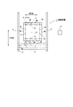
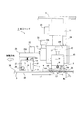
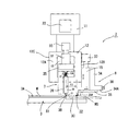
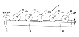
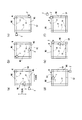
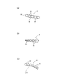
本発明の一実施例を示す概略の平面図。1 is a schematic plan view showing an embodiment of the present invention. 図1に示す加工ヘッドの左側面図。The left view of the processing head shown in FIG. 図2の正面図。The front view of FIG. 図2の要部の配置関係を示す拡大図。The enlarged view which shows the arrangement | positioning relationship of the principal part of FIG. 図1に示す割断装置の作動工程を示す平面図であり、図5(a)は一方の加工ヘッドにより割断予定線S1に沿ってガラスを割断する工程を示し、図5(b)は他方の加工ヘッドにより割断予定線S2に沿ってガラスを割断する工程を示し、図5(c)は一方の加工ヘッドを90度回転させた退避状態を示し、図5(d)は一方の加工ヘッドで割断予定線S3に沿ってガラスを割断するとともに、他方の加工ヘッドを90度回転させた退避状態を示し、図5(e)は他方の加工ヘッドにより割断予定線S4に沿ってガラスを割断する工程を示し、さらに図5(f)は他方の加工ヘッドによりガラスの割断が完了した状態を示している。It is a top view which shows the operation | movement process of the cleaving apparatus shown in FIG. 1, Fig.5 (a) shows the process of cleaving glass along the cutting line S1 with one process head, FIG.5 (b) is the other. FIG. 5 (c) shows a retracted state in which one processing head is rotated by 90 degrees, and FIG. 5 (d) shows one of the processing heads. FIG. 5E shows a retracted state in which the glass is cut along the planned cutting line S3 and the other processing head is rotated by 90 degrees, and FIG. 5E shows that the other processing head cuts the glass along the planned cutting line S4. The process is shown, and FIG. 5 (f) shows a state where the cleaving of the glass is completed by the other processing head. 本発明の押し込み手段に関する他の実施例を示す概略の正面図であり、図6(a)は複数の押し込みローラに無端状ベルトを架け渡した実施例を示し、図6(b)は外径が徐々に大きくなる複数の押し込みローラを用いた実施例を示し、さらに、図6(c)は外径が同一の複数の押し込みローラを軸心が徐々に下がるように配置した実施例を示している。FIG. 6 (a) is a schematic front view showing another embodiment relating to the pushing means of the present invention, FIG. 6 (a) shows an embodiment in which an endless belt is bridged over a plurality of pushing rollers, and FIG. 6 (b) is an outer diameter. Fig. 6 (c) shows an embodiment in which a plurality of pushing rollers having the same outer diameter are arranged so that the axis is gradually lowered. Yes.

以下図示実施例について本発明を説明すると、図1ないし図3において1は脆性材料としての板状のガラスWを割断する割断装置である。この割断装置1は一対の加工ヘッド2、2’を備えており、加工テーブル3上にガラスWが搬入されたら、上記加工ヘッド2,2’によってガラスWを割断予定線S1〜S4に沿って割断するようになっており、それによって所定寸法の正方形の製品W’を切り出すようになっている。
割断装置1は、所要の間隔を隔てて水平面のY方向に配置された左右一対のY方向ベース4、4’と、上記Y方向と直交するX方向に配置されるとともに両端部を上記Y方向ベース4,4’上に載置された一対のX方向ベース5、5’と、上記各Y方向ベース4,4’の間であって、かつX方向ベース5、5’よりも低い位置に水平に配置された加工テーブル3と、上記各X方向ベース5、5’の下面にX方向に移動可能に取り付けられた一対の加工ヘッド2、2’と、これら加工ヘッド2、2’等の駆動源の作動を制御する制御装置6とを備えている。
The present invention will be described below with reference to the illustrated embodiments. In FIGS. 1 to 3, reference numeral 1 denotes a cleaving apparatus for cleaving a plate-like glass W as a brittle material. The cleaving apparatus 1 includes a pair of processing heads 2 and 2 ′. When the glass W is loaded onto the processing table 3, the processing heads 2 and 2 ′ cut the glass W along the planned cutting lines S1 to S4. The product is cut, thereby cutting out a square product W ′ having a predetermined size.
The cleaving device 1 is arranged in a pair of left and right Y-direction bases 4 and 4 ′ arranged in the Y direction on the horizontal plane with a required interval, and arranged in the X direction orthogonal to the Y direction and has both ends at the Y direction. Between the pair of X-direction bases 5 and 5 ′ placed on the bases 4 and 4 ′ and the Y-direction bases 4 and 4 ′ and at a position lower than the X-direction bases 5 and 5 ′. A processing table 3 disposed horizontally, a pair of processing heads 2 and 2 ′ attached to the lower surfaces of the X-direction bases 5 and 5 ′ so as to be movable in the X direction, and the processing heads 2 and 2 ′. And a control device 6 for controlling the operation of the drive source.

加工テーブル3は正方形に形成されるとともに、隣り合う2辺が上記X方向とY方向に平行となるように固定して配置されている。加工テーブル3の載置面3Aは所定高さで水平に維持されるとともに、載置面3Aの形状は、製品W’と同じ寸法の正方形となるように隣接外方部分3Cよりも所定高さ(1〜15mm程度)盛り上げて形成されている(図3参照)。そのため、載置面3Aの輪郭となる四辺3Bは、隣接外方部分3Cよりも高さが高い段部となり、かつX方向またはY方向と平行になっている。また、加工テーブル3の載置面3Aの全域にわたって多数の図示しない吸引孔を開口させてあり、これらの吸引孔に負圧源から負圧を作用させることにより、載置面3A上に供給されたガラスWを吸着・保持できるようになっている。   The processing table 3 is formed in a square shape, and is fixedly arranged so that two adjacent sides are parallel to the X direction and the Y direction. The mounting surface 3A of the processing table 3 is maintained horizontally at a predetermined height, and the mounting surface 3A has a predetermined height higher than the adjacent outer portion 3C so as to be a square having the same dimensions as the product W ′. It is formed by raising (about 1 to 15 mm) (see FIG. 3). Therefore, the four sides 3B that are the outline of the placement surface 3A are stepped portions that are higher than the adjacent outer portion 3C, and are parallel to the X direction or the Y direction. In addition, a large number of suction holes (not shown) are opened over the entire area of the mounting surface 3A of the processing table 3, and the suction holes are supplied onto the mounting surface 3A by applying a negative pressure from a negative pressure source. The glass W can be adsorbed and held.

割断装置1の加工対象となるガラスWの厚さは、0.5mm〜2.3mmであって、予め略正方形に切り揃えられている。そして、被加工物としてのガラスWは、図示しないロボットハンドにより加工テーブル3の載置面3A上に供給されるとともに、割断された後の製品W’は上記ロボットハンドによって保持されて加工テーブル3上から排出されるようになっている。本実施例では、上記ロボットハンドによってガラスWが載置面3Aに供給されると、このガラスWの隣合う2辺がX方向またはY方向と揃うように位置決めされるとともに、ガラスWの四辺は載置面3Aの四辺3Bよりも外方側まで張り出した状態となる。そして、このように位置決めされたガラスWは、上記多数の吸引孔に作用する負圧によって載置面3A上に水平状態で吸着・保持されるようになっている。   The thickness of the glass W to be processed by the cleaving device 1 is 0.5 mm to 2.3 mm, and is preliminarily cut into a substantially square shape. The glass W as the workpiece is supplied onto the mounting surface 3A of the processing table 3 by a robot hand (not shown), and the product W ′ after being cut is held by the robot hand and processed by the processing table 3. It comes to be discharged from the top. In the present embodiment, when the glass W is supplied to the placement surface 3A by the robot hand, the two adjacent sides of the glass W are positioned so as to be aligned with the X direction or the Y direction, and the four sides of the glass W are It will be in the state protruded to the outward side rather than the four sides 3B of the mounting surface 3A. And the glass W positioned in this way is attracted | sucked and hold | maintained in a horizontal state on the mounting surface 3A by the negative pressure which acts on the said many suction holes.

各X方向ベース5,5’は、Y方向ベース4,4’に設けられた図示しないY方向移動手段によって各々独立してY方向ベース4,4’上をY方向に平行移動されるようになっている。各加工ヘッド4,4’は、各X方向ベース5,5’に設けられた図示しないX方向移動手段によってX方向ベース5(5’)に沿ってX方向に平行移動されるようになっている。上記Y方向移動手段およびX方向移動手段の作動は、制御装置6によって制御されるようになっている。制御装置6は、Y方向移動手段およびX方向移動手段の作動を制御することにより、各加工ヘッド2,2’をX方向又はY方向に移動させることができる。
後に詳述するが、制御装置6がX方向移動手段およびY方向移動手段を介して各加工ヘッド2,2’を載置面3Aの四辺3Bに沿ってX方向またはY方向に移動させると、スクライブ溝形成手段7によってガラスWの上面に割断予定線S1〜S4に沿ってスクライブ溝が形成され、その後、該スクライブ溝よりも外方となるスクラップ部分WSが押し込み手段8によって押し下げられる。これにより、割断予定線S1〜S4に沿ってガラスWが直線状に割断されるので、所定寸法の正方形の製品W’が切り出されるようになっている。
なお、上記X方向移動手段およびY方向移動手段の構成は、例えば特開2008−132616号公報で公知であるため、それらの詳細な構成の説明は省略する。
The X direction bases 5 and 5 ′ are independently translated in the Y direction on the Y direction bases 4 and 4 ′ by Y direction moving means (not shown) provided on the Y direction bases 4 and 4 ′. It has become. Each processing head 4, 4 ′ is translated in the X direction along the X direction base 5 (5 ′) by an X direction moving means (not shown) provided on each X direction base 5, 5 ′. Yes. The operations of the Y direction moving means and the X direction moving means are controlled by the control device 6. The control device 6 can move each machining head 2, 2 ′ in the X direction or the Y direction by controlling the operation of the Y direction moving means and the X direction moving means.
As will be described in detail later, when the control device 6 moves the machining heads 2 and 2 ′ in the X direction or the Y direction along the four sides 3B of the mounting surface 3A via the X direction moving unit and the Y direction moving unit, A scribe groove is formed on the upper surface of the glass W by the scribe groove forming means 7 along the planned cutting lines S <b> 1 to S <b> 4, and thereafter, the scrap portion WS that is outward from the scribe groove is pushed down by the pushing means 8. Thereby, since the glass W is cut linearly along the cutting planned lines S1 to S4, a square product W ′ having a predetermined size is cut out.
Note that the configurations of the X-direction moving unit and the Y-direction moving unit are well known in, for example, Japanese Patent Application Laid-Open No. 2008-132616, and a detailed description thereof will be omitted.

しかして、図2ないし図3に示すように、一方のX方向ベース5に配置された加工ヘッド2は、上端部をX方向ベース5にX方向に移動可能に取り付けられた鉛直方向のヘッドベース11と、このヘッドベース11の下部に昇降自在に取り付けられたサイコロ形のユニットフレーム12と、このユニットフレーム12の正面となる側面12Aに昇降ガイド13を介して昇降自在に設けられた上記スクライブ溝形成手段7と、上記側面12Aに隣接するユニットフレーム12の左方の側面12Bに昇降ガイド15を介して昇降自在に設けられた押し込み手段8とを備えている。
ヘッドベース11の下部にユニットフレーム12が取り付けられ、該ユニットフレーム12にスクライブ溝形成手段7と押し込み手段8が設けられているので、前述したX方向移動手段によってヘッドベース11をX方向ベース5の長手方向に移動させることで、加工ヘッド2全体がX方向ベース5に沿ってX方向に移動することができる。本実施例では、図2に示すように、ガラスWを割断するために加工ヘッド2が割断予定線S1に沿って移動される際には、移動方向前方側、つまり加工方向の前方側にスクライブ溝形成手段7のスクライバー21を位置させるとともに、加工方向の後方側に押し込み手段8を位置させるようにしている。それにより、加工ヘッド2が割断予定線S1に沿って移動される際には、割断予定線S1となるガラスWの上面にスクライバー21によって先ずスクライブ溝が形成され、その直後に該スクライブ溝よりも外方まで張り出したスクラップ部分WSが押し込み手段8の複数の押し込みローラ22によって押し下げられるようになっている。そのため、ガラスWの上面における割断予定線S1のスクライブ溝からガラスWの下面までクラックが到達して、割断予定線S1のとおりにガラスWが割断されるようになっている。つまり、内方側となる正方形の製品W’とそれよりも外方のスクラップ部分WSとが分離されるようになっている。
As shown in FIGS. 2 to 3, the machining head 2 arranged on one X-direction base 5 has a vertical head base attached to the X-direction base 5 so that its upper end is movable in the X-direction. 11, a dice-shaped unit frame 12 attached to the lower part of the head base 11 so as to be movable up and down, and the scribe groove provided on the side surface 12A which is the front surface of the unit frame 12 via the lifting guide 13 Forming means 7 and pushing means 8 provided on the left side surface 12B of the unit frame 12 adjacent to the side surface 12A so as to be movable up and down via a lifting guide 15 are provided.
Since the unit frame 12 is attached to the lower part of the head base 11 and the scribe groove forming means 7 and the pushing means 8 are provided in the unit frame 12, the head base 11 is attached to the X direction base 5 by the X direction moving means described above. By moving in the longitudinal direction, the entire machining head 2 can move in the X direction along the X direction base 5. In the present embodiment, as shown in FIG. 2, when the processing head 2 is moved along the planned cutting line S1 in order to cleave the glass W, the scribing is performed forward in the movement direction, that is, in front of the processing direction. The scriber 21 of the groove forming means 7 is positioned, and the pushing means 8 is positioned on the rear side in the processing direction. Thereby, when the processing head 2 is moved along the planned cutting line S1, a scribe groove is first formed on the upper surface of the glass W that becomes the planned cutting line S1 by the scriber 21, and immediately after that the scribe groove The scrap portion WS projecting outward is pushed down by a plurality of pushing rollers 22 of the pushing means 8. Therefore, a crack reaches from the scribe groove of the cutting planned line S1 on the upper surface of the glass W to the lower surface of the glass W, and the glass W is cut as the cutting planned line S1. That is, the square product W ′ on the inner side is separated from the scrap portion WS on the outer side.

ヘッドベース11における中央部よりも下部は、上部に対して回転自在となっており、かつ図示しない連動機構を介してモータ23と連動している。モータ23は制御装置6によって制御されるようになっており、制御装置6は所要時にモータ23を正逆に所定量回転させるようになっている。それにより、上記連動機構を介してヘッドベース11の下部は、ヘッドベース11の鉛直方向の軸心を中心として交互に90度回動されるので、ユニットフレーム12とそれに設けられたスクライブ溝形成手段7および押し込み手段8も水平面で90度回転される。それにより、ユニットフレーム12に設けられたスクライブ溝形成手段7がX方向に移動可能な状態と、Y方向に移動可能な状態に切り換えられるようになっている。つまり、加工ヘッド2は、X方向の割断予定線S1に沿って移動することができるとともに、Y方向の割断予定線S3に沿って移動することができるようになっている。   The lower part of the head base 11 than the central part is rotatable with respect to the upper part, and is interlocked with the motor 23 via an interlocking mechanism (not shown). The motor 23 is controlled by the control device 6, and the control device 6 rotates the motor 23 by a predetermined amount in the forward and reverse directions when necessary. Thereby, the lower part of the head base 11 is rotated 90 degrees alternately around the vertical axis of the head base 11 through the interlocking mechanism, so that the unit frame 12 and the scribe groove forming means provided on the unit frame 12 are provided. 7 and pushing means 8 are also rotated 90 degrees in the horizontal plane. Thereby, the scribe groove forming means 7 provided in the unit frame 12 can be switched between a state movable in the X direction and a state movable in the Y direction. That is, the machining head 2 can move along the planned cutting line S1 in the X direction and can move along the planned cutting line S3 in the Y direction.

ユニットフレーム12はヘッドベース11の下部に対して昇降可能に取り付けられており、ヘッドベース11に設けられたエアシリンダ24によってユニットフレーム12は昇降されるようになっている。つまり、エアシリンダ24によってユニットフレーム12を昇降させることで、スクライブ溝形成手段7および押し込み手段8を上昇端位置と下降端位置とに昇降させることができる。上記ユニットフレーム12は、エアシリンダ24が上死点の時に上昇端となる待機位置となり、他方、エアシリンダ24が下死点の少し手前の高さとなると、図示しないストッパによりユニットフレーム12の下降端位置が規制されるようになっている。ユニットフレーム12が下降端位置にある時がスクライブ溝形成手段7および押し込み手段8がガラスWに加工を施すことが可能な加工位置となっている。   The unit frame 12 is attached to the lower part of the head base 11 so as to be movable up and down, and the unit frame 12 is moved up and down by an air cylinder 24 provided on the head base 11. That is, by raising and lowering the unit frame 12 by the air cylinder 24, the scribe groove forming means 7 and the pushing means 8 can be raised and lowered to the rising end position and the falling end position. The unit frame 12 is in a standby position that is an ascending end when the air cylinder 24 is at the top dead center. The position is regulated. When the unit frame 12 is at the lower end position, the scribe groove forming means 7 and the pushing means 8 are processing positions at which the glass W can be processed.

次に、スクライブ溝形成手段7は、昇降ガイド13に昇降自在に取り付けられたL字形のブラケット25と、このブラケット25に支持ピン26を介して揺動自在に取り付けられたL字形のアーム27と、このアーム27の水平部27Aに鉛直下方に向けて連結されたホルダ28と、このホルダ28の下端部に回転自在に取り付けられた円盤状の上記スクライバー21とを備えている。
スクライバー21はホルダ28の下端に回転自在に設けられており、スクライバー21の外周部全域は断面が鋭角となっている。このスクライバー21の外周部がガラスWの上面に押圧された状態で回転されることで、ガラスWの上面にスクライブ溝が形成されるようになっている。
アーム27の水平部27Aとその上方のブラケット25の水平部25Aとにわたって引っ張りばね31が設けられており、それによって、アーム27の水平部27とホルダ28およびスクライバー21は常時ブラケット25の水平部25Aに向けて上方へ付勢されている。他方、ブラケット25の水平部25Aには、プッシャ32Aを下方に向けてエアシリンダ32が取り付けられており、上記プッシャ32Aはホルダ28の上端に当接されている。これにより、エアシリンダ32によってホルダ28を介してスクライバー21に所定圧力が加えられており、その状態でスクライバー21によってガラスWの上面にスクライブ溝が形成されるようになっている。
そして、前述したモータ23によってユニットフレーム12を水平面で90度交互に回転させた際には、上記アーム27の水平部27Aの伸びる方向およびスクライバー21により形成されるスクライブ溝の延びる方向がX方向またはY方向と平行となるように構成されている。本実施例においては、加工ヘッド2がX方向又はY方向に移動される際には、スクライブ溝形成手段7が押し込み手段8よりも先行して移動するようになっている。
ブラケット25は昇降ガイド13に昇降自在に取り付けられており、また、このブラケット25は、ユニットフレーム12に取り付けられたサーボモータ33に連動して昇降可能となっている。サーボモータ33の作動は制御装置6によって制御されるようになっており、制御装置6はサーボモータ33を介してブラケット25の高さを、つまり、スクライバー21の高さを所定高さに設定可能となっている。これにより、スクライバー21によってガラスWにスクライブ溝を形成する際の切り込み深さを調整できるようになっている。スクライブ溝形成手段7は以上のように構成されている。
Next, the scribe groove forming means 7 includes an L-shaped bracket 25 attached to the elevating guide 13 so as to be movable up and down, and an L-shaped arm 27 attached to the bracket 25 via a support pin 26 so as to be swingable. The holder 27 is connected to the horizontal portion 27A of the arm 27 vertically downward, and the disc-shaped scriber 21 is rotatably attached to the lower end portion of the holder 28.
The scriber 21 is rotatably provided at the lower end of the holder 28, and the entire outer peripheral portion of the scriber 21 has an acute angle in cross section. A scribe groove is formed on the upper surface of the glass W by rotating in a state where the outer peripheral portion of the scriber 21 is pressed against the upper surface of the glass W.
A tension spring 31 is provided across the horizontal portion 27A of the arm 27 and the horizontal portion 25A of the bracket 25 above the arm 27, whereby the horizontal portion 27 of the arm 27, the holder 28 and the scriber 21 are always in the horizontal portion 25A of the bracket 25. It is urged upward toward. On the other hand, an air cylinder 32 is attached to the horizontal portion 25A of the bracket 25 with the pusher 32A facing downward, and the pusher 32A is in contact with the upper end of the holder 28. Thereby, a predetermined pressure is applied to the scriber 21 by the air cylinder 32 via the holder 28, and in this state, a scribe groove is formed on the upper surface of the glass W by the scriber 21.
When the unit frame 12 is alternately rotated 90 degrees on the horizontal plane by the motor 23 described above, the extending direction of the horizontal portion 27A of the arm 27 and the extending direction of the scribe groove formed by the scriber 21 are the X direction or It is configured to be parallel to the Y direction. In this embodiment, when the machining head 2 is moved in the X direction or the Y direction, the scribe groove forming means 7 moves before the pushing means 8.
The bracket 25 is attached to the elevating guide 13 so as to be movable up and down, and the bracket 25 can be raised and lowered in conjunction with a servo motor 33 attached to the unit frame 12. The operation of the servo motor 33 is controlled by the control device 6, and the control device 6 can set the height of the bracket 25 via the servo motor 33, that is, the height of the scriber 21 to a predetermined height. It has become. Thereby, the cutting depth when the scribe groove is formed in the glass W by the scriber 21 can be adjusted. The scribe groove forming means 7 is configured as described above.

次に、押し込み手段8は、昇降ガイド15に昇降自在に設けられた板状のブラケット34と、このブラケット34における下部の水平部34Aに水平方向に移動可能に取り付けられたローラホルダ35と、このローラホルダ35に回転自在に取り付けられた複数の押し込みローラ22とを備えている。
ブラケット34は、ユニットフレーム12に設けられたサーボモータ37に連動して昇降されるようになっており、このサーボモータ37の作動は制御装置6によって制御されるようになっている。制御装置6はサーボモータ37を介してブラケット34の高さを、つまり、ローラホルダ35に設けられた押し込みローラ22の高さを所要の高さに設定可能となっている。
Next, the push-in means 8 includes a plate-like bracket 34 provided on the elevating guide 15 so as to be movable up and down, a roller holder 35 attached to a lower horizontal portion 34A of the bracket 34 so as to be movable in the horizontal direction, And a plurality of push rollers 22 rotatably attached to the roller holder 35.
The bracket 34 is moved up and down in conjunction with a servo motor 37 provided on the unit frame 12, and the operation of the servo motor 37 is controlled by the control device 6. The control device 6 can set the height of the bracket 34 via the servo motor 37, that is, the height of the pushing roller 22 provided in the roller holder 35 to a required height.

ローラホルダ35には、ユニットフレーム12の側面12Bの長手方向に沿って、つまり、上記スクライバー21が移動される際の移動方向に沿って所定間隔で複数の貫通孔35Aが穿設されており、これらの貫通孔35Aに各押し込みローラ22の支持軸を着脱自在に嵌合できるようになっている。
本実施例においては、移動方向においてスクライバー21よりも後方側に押し込みローラ22が配置されており、かつ、スクライバー21の移動軌跡に対して、直交方向に距離L3ずらして各押し込みローラ22が配置されている。上記ホルダ35の貫通孔35Aは、押し込みローラ22の数よりも多く形成されており、押し込みローラ22を選択的に貫通孔35Aのいずれかに取り付けることができるようになっている。そのため、移動方向の先頭となる押し込みローラ22を嵌合させる貫通孔35Aを変更することで、スクライバー21と先頭の押し込みローラ22との移動方向において隔てた距離L1を変更することができるとともに、先頭の押し込みローラ22と最後尾の押し込みローラ22との移動方向における距離L2を変更できるようになっている。
そして、本実施例においては、ホルダ35の貫通孔35Aは合計11個形成されており、それらの貫通孔35Aは、移動方向の前方側のものに対して後方側に位置するものが、徐々に高さが低くなるように形成されている。これにより、先頭の貫通孔35Aから最後尾の貫通孔35Aまでを結ぶ仮想の直線が、加工テーブル3上のガラスWの上面に対して5°傾斜するようになっている。そのため、同一外径を有する複数の押し込みローラ22を所要位置の貫通孔35Aに取り付けると、押し込みローラ22下端外周部を結ぶ仮想の直線と、加工テーブル3上のガラスWの上面とが成す角度も5°となる(図4参照)。このように、複数の押し込みローラ22は、加工方向後方側に位置する程、ガラスWを押し込む際の押し込み量が大きくなるように配置されている。
そして、サーボモータ37によって加工位置となる下降端に押し込みローラ22が位置した状態では、加工方向の先頭の押し込みローラ22の下端外周の高さは、スクライバー21の下端外周部の高さと同じか僅かに低い位置に保持され、移動方向(加工方向)の順次後方側に位置する押し込みローラの下端外周の高さは、スクライバー21の下端外周部よりも徐々に高さが低い位置に保持されるようになっている。そのため、スクライバー21によって割断予定線S1にスクライブ溝が形成された直後に、移動方向の先頭位置の押し込みローラ22から順次後方側に位置する各押し込みローラ22が、スクライブ溝よりも外方位置のスクラップ部分WSを僅かずつ徐々に下方へ押し込むようになっている(図2〜図4参照)。それによって、割断予定線S1に形成されたスクライブ溝からガラスWの下面までクラックが伸長して、割断予定線S1に沿ってガラスWが割断されるようになっている。
さらに、本実施例においては、ローラホルダ35は、ブラケット34の水平部34Aに案内されて移動方向に対して直交方向に移動可能となっており、水平部34Aとローラホルダ35にわたって設けられた調整ねじ38を作業者が正逆に回転させることで、スクライバー21の移動軌跡(スクライブ溝)に対して押し込みローラ22が直交方向に隔てた距離L3を調整できるようになっている。押し込み手段8は以上のように構成されている。
X方向ベース5の加工ヘッド2は以上のように構成されており、この加工ヘッド2は前述したモータ23によって回転されることで、スクライバー21が移動方向の前方側となるようにX方向あるいはY方向に90°移動方向を切り換えられるようになっている。
他方のX方向ベース5’に配置された加工ヘッド2’も上述した加工ヘッド2と実質的に同様に構成されているが、加工ヘッド2’においては、スクライブ溝形成手段7を挟んでユニットフレーム12の反対側(右方)の側壁12Cに押し込み手段8が配置されている。加工ヘッド2’のその他の構成は、加工ヘッド2と同じである。このように加工ヘッド2’の押し込み手段8を上記加工ヘッド2のものとは反対側の側壁12Cに配置するのは、割断予定線S2、S4に沿って加工ヘッド2’によりガラスWを割断する際に、移動方向(加工方向)の右方側にスクラップ部分WSが生じるからである。
The roller holder 35 is provided with a plurality of through holes 35A at predetermined intervals along the longitudinal direction of the side surface 12B of the unit frame 12, that is, along the moving direction when the scriber 21 is moved. The support shafts of the push rollers 22 can be detachably fitted into the through holes 35A.
In this embodiment, push rollers 22 are arranged behind the scriber 21 in the movement direction, and the push rollers 22 are arranged at a distance L3 in the orthogonal direction with respect to the movement locus of the scriber 21. ing. The number of through-holes 35A of the holder 35 is larger than the number of push-in rollers 22, and the push-in rollers 22 can be selectively attached to any of the through-holes 35A. Therefore, by changing the through-hole 35A in which the pushing roller 22 that is the leading in the moving direction is fitted, the distance L1 that is separated in the moving direction between the scriber 21 and the leading pushing roller 22 can be changed, and the leading The distance L2 in the moving direction between the first push roller 22 and the last push roller 22 can be changed.
In the present embodiment, a total of 11 through-holes 35A of the holder 35 are formed, and those through-holes 35A that are located on the rear side with respect to the front side in the moving direction are gradually It is formed to have a low height. Thereby, a virtual straight line connecting the leading through hole 35A to the last through hole 35A is inclined by 5 ° with respect to the upper surface of the glass W on the processing table 3. Therefore, when a plurality of push rollers 22 having the same outer diameter are attached to the through hole 35A at a required position, an angle formed between a virtual straight line connecting the outer periphery of the lower ends of the push rollers 22 and the upper surface of the glass W on the processing table 3 is also obtained. 5 ° (see FIG. 4). In this way, the plurality of push rollers 22 are arranged so that the push amount when the glass W is pushed increases as the push rollers 22 are located on the rear side in the processing direction.
In the state where the pushing roller 22 is positioned at the lower end that is the machining position by the servo motor 37, the height of the outer periphery of the lower end of the pushing roller 22 at the head in the machining direction is the same as or slightly the height of the outer circumference of the lower end of the scriber 21. So that the height of the outer periphery of the lower end of the push-in roller located at the rear side in the moving direction (processing direction) is gradually lower than the outer periphery of the lower end of the scriber 21. It has become. Therefore, immediately after the scribe groove is formed on the planned cutting line S1 by the scriber 21, the push rollers 22 sequentially positioned on the rear side from the push roller 22 at the head position in the moving direction are scrapped at the outer positions than the scribe groove. The portion WS is gradually pushed downward little by little (see FIGS. 2 to 4). Thereby, the crack extends from the scribe groove formed in the planned cutting line S1 to the lower surface of the glass W, and the glass W is cut along the planned cutting line S1.
Further, in this embodiment, the roller holder 35 is guided by the horizontal portion 34A of the bracket 34 and can move in the direction orthogonal to the moving direction, and an adjustment provided across the horizontal portion 34A and the roller holder 35. When the operator rotates the screw 38 in the forward and reverse directions, the distance L3 at which the pushing roller 22 is separated in the orthogonal direction with respect to the movement locus (scribe groove) of the scriber 21 can be adjusted. The pushing means 8 is configured as described above.
The machining head 2 of the X direction base 5 is configured as described above, and this machining head 2 is rotated by the motor 23 described above, so that the scriber 21 is on the front side in the movement direction. The direction of movement by 90 ° can be switched in the direction.
The machining head 2 ′ disposed on the other X-direction base 5 ′ is also configured in substantially the same manner as the machining head 2 described above. However, in the machining head 2 ′, the unit frame is sandwiched by the scribe groove forming means 7. The pushing means 8 is disposed on the side wall 12 </ b> C on the opposite side (right side) of 12. The other configuration of the machining head 2 ′ is the same as that of the machining head 2. The reason why the pushing means 8 of the machining head 2 ′ is arranged on the side wall 12C opposite to that of the machining head 2 is to break the glass W by the machining head 2 ′ along the planned cutting lines S2 and S4. This is because the scrap portion WS is generated on the right side of the moving direction (processing direction).

以上の構成において、割断装置1の各加工ヘッド2,2’によるガラスWの割断工程は次のようにして行われる。
先ず、両方の加工ヘッド2,2’が加工テーブル3上から外れた退避位置に停止した状態において、図示しないロボットハンドにより加工対象となるガラスWが加工テーブル3の載置面3A上に搬入されると、該載置面3Aに導入されている負圧によってガラスWは吸着保持される。この時点で、正方形のガラスWの四辺は、X方向又はY方向と平行となるように位置決めされた状態となる(図1参照)。
このように加工テーブル3にガラスWが搬入される際には、各加工ヘッド2、2’は加工テーブル3上から外れた退避位置にあるが、各加工ヘッド2,2’のユニットフレーム12は、エアシリンダ24によって上昇端の待機位置に停止している。そのため、各加工ヘッド2、2’のスクライバー21と各押し込みローラ22は、加工テーブル3上のガラスWの上面よりも上方に支持されている。
In the above configuration, the cleaving process of the glass W by the processing heads 2 and 2 ′ of the cleaving apparatus 1 is performed as follows.
First, in a state where both the processing heads 2 and 2 ′ are stopped at the retracted position removed from the processing table 3, the glass W to be processed is carried onto the placement surface 3 </ b> A of the processing table 3 by a robot hand (not shown). Then, the glass W is adsorbed and held by the negative pressure introduced into the mounting surface 3A. At this point, the four sides of the square glass W are positioned so as to be parallel to the X direction or the Y direction (see FIG. 1).
As described above, when the glass W is carried into the processing table 3, each processing head 2, 2 'is in a retracted position removed from the processing table 3, but the unit frame 12 of each processing head 2, 2' is The air cylinder 24 is stopped at the rising end standby position. Therefore, the scriber 21 and each push roller 22 of each processing head 2, 2 ′ are supported above the upper surface of the glass W on the processing table 3.

次に、加工テーブル3にガラス板Wが搬入されると、上記X方向移動手段とY方向移動手段によって、一方の加工ヘッド2は、割断予定線S1の延長線上となる位置まで移動され、他方の加工ヘッド2’のスクライバー21はX方向ベースの一端上においてガラスWに向けてX方向に移動可能な状態で停止する。その後、両加工ヘッド2、2’のエアシリンダ24によってユニットフレーム12が上方の待機位置から下降端の加工位置まで下降する。これにより、各加工ヘッド2、2’のスクライバー21は、加工テーブル3上のガラスWの上面にスクライブ溝を形成可能な高さに支持されるとともに、押し込みローラ22も加工テーブル3上のガラスWの上面を押し下げることができる高さに支持される。
この状態からY方向移動手段によって一方の加工ヘッド2がガラスWに向けてY方向に所定速度で移動されるとともに、スクライバー21がガラスWの上面に当接した後はエアシリンダ32によりスクライバー21に対して所要の圧力が掛けられる。それにより、加工ヘッド2の移動方向(加工方向)前方に位置するスクライバー21がガラスWの上面における割断予定線S1の始端から順次終端に向けて転動することで、該割断予定線S1上に深さが浅い直線状のスクライブ溝が形成される(図5(a)参照)。また、このように先行するスクライバー21の移動に追従して押し込み手段8の複数の押し込みローラ22は、その先頭のものから後続するものが順次、上記スクライブ溝が形成された割断予定線S1よりも外方のスクラップ部分WSを徐々に押し下げる(図2〜図4参照)。このように複数の押し込みローラ22は、加工方向において後方に位置するものほど高さが低くなっている。つまり、複数の押し込みローラ22は、加工方向において後方に位置するものほど押し込み量が大きくなっている。そのため、割断予定線S1に形成されたスクライブ溝を境として、そこよりも外方となるスクラップ部分WSが複数の押し込みローラ22によって徐々に押し下げられる。それにより、ガラスWの上面のスクライブ溝からガラスWの下面までクラックが生じることで、割断予定線S1に沿ってガラスWの一辺が切り離される(図2、図5(a)、図5(b)参照)。
Next, when the glass plate W is carried into the processing table 3, the one processing head 2 is moved to a position on the extension line of the cutting planned line S1 by the X-direction moving means and the Y-direction moving means, and the other The scriber 21 of the machining head 2 ′ stops in a state of being movable in the X direction toward the glass W on one end of the X direction base. Thereafter, the unit cylinder 12 is lowered from the upper standby position to the lower end processing position by the air cylinders 24 of both processing heads 2 and 2 '. As a result, the scriber 21 of each processing head 2, 2 ′ is supported at a height at which a scribe groove can be formed on the upper surface of the glass W on the processing table 3, and the push roller 22 also has the glass W on the processing table 3. Is supported at a height at which the upper surface of the can be pushed down.
From this state, one processing head 2 is moved in the Y direction at a predetermined speed toward the glass W by the Y direction moving means, and after the scriber 21 comes into contact with the upper surface of the glass W, the air cylinder 32 moves the scriber 21 to the scriber 21. On the other hand, the required pressure is applied. As a result, the scriber 21 positioned in the front of the processing head 2 in the moving direction (processing direction) rolls sequentially from the start end of the cutting planned line S1 on the upper surface of the glass W toward the end, so that the cutting target line S1 A linear scribe groove having a shallow depth is formed (see FIG. 5A). Further, the plurality of push rollers 22 of the push means 8 following the movement of the preceding scriber 21 are sequentially from the head of the push rollers 22 sequentially from the planned cutting line S1 in which the scribe groove is formed. The outer scrap portion WS is gradually pushed down (see FIGS. 2 to 4). As described above, the plurality of push rollers 22 are lower in height as they are located rearward in the processing direction. That is, the pushing amount of the plurality of pushing rollers 22 is larger as the pushing roller 22 is located rearward in the processing direction. For this reason, the scrap portion WS that is outward from the scribe groove formed in the planned cutting line S <b> 1 is gradually pushed down by the plurality of pushing rollers 22. Thereby, a crack is generated from the scribe groove on the upper surface of the glass W to the lower surface of the glass W, so that one side of the glass W is cut along the planned cutting line S1 (FIGS. 2, 5A, 5B). )reference).

加工ヘッド2によるガラスWの割断が割断予定線S1の半ば程度まで進んだ段階において、Y方向移動手段によって他方の加工ヘッド2’が割断予定線S2の延長線上の位置まで移動された後に、X方向移動手段により加工ヘッド2’はガラスWの割断予定線S2に向けて所定速度で移動される。そのため、X方向に移動される加工ヘッド2’の移動方向(加工方向)前方となるスクライバー21がガラスWの上面の割断予定線S2上を始端部から終端部に向けて転動する。これにより、割断予定線S2上に直線状のスクライブ溝が形成される(図5(a)、図5(b)参照)。また、先行するスクライバー21の移動に追従して押し込み手段8の複数の押し込みローラ22は、上述した加工ヘッド2の場合と同様に、先頭のものから後続するものが順次割断予定線S2よりも外方(右方)のスクラップ部分WSを押し下げる。このように、高さが徐々に低くなる(押し込み量が徐々に大きくなる)複数の押し込みローラ22によってスクラップ部分WSが押し下げられることにより、割断予定線S2のスクライブ溝からガラスWの下面までクラックが生じて、割断予定線S2に沿ってガラスWの一辺が切り離される(図5(b)、図5(c)参照)。
他方、先行した加工ヘッド2は、割断予定線S1に沿ってガラスWの1辺を割断したら、モータ23により時計方向に90°回転されて、移動方向をX方向に切り換えられるとともに、X方向移動手段とY方向移動手段によって、割断予定線S3の延長線上となる退避位置に待機する(図5(c)参照)。
この後、他方の加工ヘッド2’による割断予定線S2に沿ったガラスWの割断が終了すると、加工ヘッド2は、X方向移動手段によってガラスWに向けてX方向に所定速度で移動される。それにより、加工ヘッド2の移動方向前方に位置するスクライバー21がガラスWの上面の割断予定線S3上を始端部から終端部に向けて転動することで、該割断予定線S3上に直線状のスクライブ溝が形成される(図5(c)、図5(d)参照)。また、先行するスクライバー21の移動に追従して押し込み手段8の複数の押し込みローラ22は、先頭のものから後続するものが順次、割断予定線S3よりも外方(左方)のスクラップ部分WSを押し下げる。複数の押し込みローラ22によってスクラップ部分WSが徐々に押し下げられることにより、ガラスWの上面のスクライブ溝からガラスWの下面までクラックが生じて、割断予定線S3に沿ってガラスWの一辺が割断されて切り離される(図5(d)、図5(e)参照)。
After the cutting of the glass W by the processing head 2 has progressed to about the middle of the planned cutting line S1, the other processing head 2 'is moved to a position on the extension line of the planned cutting line S2 by the Y-direction moving means, and then X The processing head 2 ′ is moved at a predetermined speed toward the planned cutting line S 2 of the glass W by the direction moving means. Therefore, the scriber 21 in front of the movement direction (processing direction) of the processing head 2 ′ moved in the X direction rolls on the planned cutting line S <b> 2 on the upper surface of the glass W from the start end portion toward the end portion. As a result, a linear scribe groove is formed on the planned cutting line S2 (see FIGS. 5A and 5B). Further, the plurality of pushing rollers 22 of the pushing means 8 following the movement of the preceding scriber 21 are sequentially separated from the planned cutting line S2 from the leading one in the same manner as the processing head 2 described above. Push down the scrap part WS on the right side. As described above, the scrap portion WS is pushed down by the plurality of pushing rollers 22 whose height is gradually lowered (the amount of pushing is gradually increased), so that a crack is generated from the scribe groove of the planned cutting line S2 to the lower surface of the glass W. It arises and one side of the glass W is cut along the planned cutting line S2 (see FIGS. 5B and 5C).
On the other hand, when the preceding processing head 2 cuts one side of the glass W along the planned cutting line S1, it is rotated 90 ° clockwise by the motor 23 to switch the moving direction to the X direction and move in the X direction. By the means and the Y-direction moving means, it stands by at the retracted position that is on the extension line of the planned cutting line S3 (see FIG. 5C).
Thereafter, when the cutting of the glass W along the planned cutting line S2 by the other processing head 2 ′ is completed, the processing head 2 is moved toward the glass W at a predetermined speed in the X direction by the X direction moving means. As a result, the scriber 21 located in front of the processing head 2 in the moving direction rolls on the planned cutting line S3 on the upper surface of the glass W from the starting end portion toward the terminal end portion. Are formed (see FIGS. 5C and 5D). Further, the plurality of push rollers 22 of the push means 8 following the movement of the preceding scriber 21 are sequentially followed by the scrap portion WS outward (leftward) from the planned cutting line S3. Press down. The scrap portion WS is gradually pushed down by the plurality of pushing rollers 22, so that a crack is generated from the scribe groove on the upper surface of the glass W to the lower surface of the glass W, and one side of the glass W is cut along the planned cutting line S <b> 3. They are separated (see FIG. 5 (d) and FIG. 5 (e)).

他方の加工ヘッド2’は、上記一方の加工ヘッド2が割断予定線S3に沿ってガラスWを割断している間に、割断予定線S2に沿ってガラスWの1辺の割断を終了するようになっており、その後、モータ23により加工ヘッド2’は反時計方向に90°回転されて、移動方向をY方向に切り換えられるとともに、X方向移動手段とY方向移動手段によって割断予定線S4の延長線上となる退避位置に待機する(図5(c)、図5(d)参照)。
この後、上記加工ヘッド2による割断予定線S3に沿ったガラスWの一辺の割断が半ばまで進んだ段階で、加工ヘッド2’はY方向移動手段によってガラスWに向けてY方向に所定速度で移動される(図5(d)、図5(e)参照)。それにより、加工ヘッド2’の移動方向前方に位置するスクライバー21がガラスWの上面の割断予定線S4上を始端部から終端部に向けて転動することで、該割断予定線S4上に直線状のスクライブ溝が形成される。このように先行するスクライバー21の移動に追従して押し込み手段8の複数の押し込みローラ22は、先頭のものから後続するものが順次、割断予定線S4よりも外方(右方)のスクラップ部分WSを押し下げる。このように複数の押し込みローラ22によってスクライブ溝よりも外方(右方)のスクラップ部分WSが押し下げられることにより、ガラスWの上面のスクライブ溝からガラスWの下面までクラックが生じて、割断予定線S4に沿ってガラスWの一辺が切り離される(図5(e)、図5(f)参照)。
この時までには、一方の加工ヘッド2による割断予定線S3に沿ったガラスWの一辺の割断は終了しており、加工ヘッド2はX方向移動手段およびY方向移動手段によって加工テーブル3上から外れた退避位置に停止している(図5(e)、図5(f)参照)。
このようにして、割断予定線S1〜S4のとおりにガラスWの四辺が割断されて、スクラップ部分WSが切り離されるようになっており、それによって製品W’が切り出されるようになっている。このように本実施例においては、正方形のガラスWにおける隣り合う辺を各割断予定線S1〜S4に沿って各加工ヘッド2,2’によって割断することで、製品W’を切り出すようにしている。
そして、加工テーブル3上の製品W’は、図示しないロボットハンドによって保持されて加工テーブル3上から排出されるようになっており、その後、ロボットハンドによって新たな加工対象となるガラスWが加工テーブル3上に搬入される。
なお、ガラスWの上面に各加工ヘッド2,2’のスクライバー21によってスクライブ溝を形成する際の切り込みの深さは、上記サーボモータ33によるスクライバー21の支持高さを変更することで調整することができる。また、押し込み手段8の押し込みローラ22によってスクラップ部分WSを押し下げる押し込み量は、サーボモータ37によって押し込みローラ22の支持高さを変えることで調整することができる。このように、本実施例においては、スクライバー21と先頭の押し込みローラ22との距離L1、押し込みローラ22の配置長さL2およびスクライバー21の移動軌跡に対する押し込みローラ22の直交方向での距離L3を調整することができるので、ガラスWの材質や厚さに応じて最適な割断のための加工条件を選択することができる。
The other processing head 2 ′ ends the cleaving of one side of the glass W along the planned cutting line S2 while the one processing head 2 is cutting the glass W along the planned cutting line S3. After that, the machining head 2 ′ is rotated 90 ° counterclockwise by the motor 23 to switch the movement direction to the Y direction, and the cutting line S4 is cut by the X direction movement means and the Y direction movement means. It stands by at the retracted position on the extension line (see FIGS. 5C and 5D).
Thereafter, when the cutting of one side of the glass W along the planned cutting line S3 by the processing head 2 has progressed to the middle, the processing head 2 ′ is moved toward the glass W by the Y-direction moving means at a predetermined speed in the Y direction. It is moved (see FIG. 5 (d) and FIG. 5 (e)). As a result, the scriber 21 located in front of the processing head 2 ′ in the moving direction rolls on the planned cutting line S4 on the upper surface of the glass W from the starting end portion toward the terminal end portion. A scribe groove is formed. In this way, the plurality of pushing rollers 22 of the pushing means 8 following the movement of the preceding scriber 21 are sequentially from the head to the scrap portion WS outward (rightward) from the cutting planned line S4. Press down. Thus, by pushing down the scrap part WS outward (right side) from the scribe groove by the plurality of pushing rollers 22, a crack is generated from the scribe groove on the upper surface of the glass W to the lower surface of the glass W, and the planned cutting line One side of the glass W is cut along S4 (see FIGS. 5E and 5F).
By this time, the cutting of one side of the glass W along the planned cutting line S3 by one of the processing heads 2 has been completed, and the processing head 2 is removed from the processing table 3 by the X direction moving means and the Y direction moving means. It has stopped at the retracted position (see FIGS. 5 (e) and 5 (f)).
In this way, the four sides of the glass W are cleaved as indicated by the planned cutting lines S1 to S4, and the scrap portion WS is cut off, thereby cutting out the product W ′. Thus, in the present embodiment, the product W ′ is cut out by cleaving adjacent sides in the square glass W by the processing heads 2 and 2 ′ along the respective planned cutting lines S1 to S4. .
The product W ′ on the processing table 3 is held by a robot hand (not shown) and is discharged from the processing table 3. Thereafter, the glass W to be newly processed by the robot hand is moved to the processing table. 3 is carried in.
The depth of the cut when the scriber 21 of each processing head 2, 2 ′ is formed on the upper surface of the glass W is adjusted by changing the support height of the scriber 21 by the servo motor 33. Can do. Further, the amount of pushing down the scrap portion WS by the pushing roller 22 of the pushing means 8 can be adjusted by changing the support height of the pushing roller 22 by the servo motor 37. As described above, in this embodiment, the distance L1 between the scriber 21 and the leading pushing roller 22, the arrangement length L2 of the pushing roller 22, and the distance L3 in the orthogonal direction of the pushing roller 22 with respect to the movement trajectory of the scriber 21 are adjusted. Therefore, it is possible to select processing conditions for optimal cleaving according to the material and thickness of the glass W.

上述した本実施例の割断装置1によれば、押し込み手段8の複数の押し込みローラ22は、移動方向(加工方向)の前方のものに対して後方のものが順次押し込み量が大きくなっている。したがって、押し込みローラ22がスクラップ部分WSを押し下げる際には、移動方向後方側の押し込みローラ22による折り曲げる力が徐々に大きくなる。そのため、スクライブ溝に先行してガラスWにクラックが入ることを確実に防止することができ、無理なく確実にガラスWを割断することができる。そのため、割断後におけるガラスWの割断面が荒れることを防止することができる。
また、本実施例によれば、ローラホルダ35に形成する貫通孔35Aの位置を変更することにより、複数の押し込みローラ22によるスクラップ部分WSの押し込み量を容易に設定することができる。また、本実施例の押し込み手段8は、上述した従来の割断装置のものと比較して簡易な構成でありながら、ガラスWを安定して割断することが可能である。
さらに、本実施例においては、被加工物であるガラスWの材質や厚さ等の違いに応じて押し込み手段8の押し込みローラ22の押し込み量を調整することができるので、ガラスWを割断する際の加工精度を向上させることができる。
According to the cleaving device 1 of this embodiment described above, the plurality of pushing rollers 22 of the pushing means 8 are sequentially pushed in a larger amount in the rear direction than in the moving direction (processing direction). Therefore, when the pushing roller 22 pushes down the scrap portion WS, the bending force by the pushing roller 22 on the rear side in the moving direction gradually increases. Therefore, it is possible to reliably prevent the glass W from being cracked prior to the scribe groove, and the glass W can be cleaved without difficulty. For this reason, it is possible to prevent the fractured surface of the glass W after cleaving from becoming rough.
Further, according to the present embodiment, by changing the position of the through hole 35 </ b> A formed in the roller holder 35, the pushing amount of the scrap portion WS by the plurality of pushing rollers 22 can be easily set. Further, the pushing means 8 of the present embodiment can break the glass W stably while having a simple configuration as compared with that of the conventional cleaving apparatus described above.
Furthermore, in this embodiment, the amount of pushing of the pushing roller 22 of the pushing means 8 can be adjusted according to the difference in the material, thickness, etc. of the glass W that is the workpiece. The machining accuracy can be improved.

次に、図6(a)〜図6(c)は、本発明の加工ヘッド2(2’)の押し込み手段8に用いる複数の押し込みローラ22の配置に関する他の実施例を示したものである。すなわち、図6(a)は、複数の押し込みローラ22の外周部にわたって1本の無端状ベルト51を掛け渡したものであり、図6(b)は移動方向における後方側に位置するもの程、押し込みローラ22の外径を徐々に大きくしたものである。さらに、図6(c)は、複数の押し込みローラ22を移動方向の後方側に位置する程、徐々に高さを低くして、各押し込みローラ22の下端外周部を結ぶ仮想線L10が凸状の円弧となるようにしたものである。
図6(a)〜図6(c)に示した各実施例の押し込み手段8を採用することで、上述した第1実施例と同様の作用・効果を得ることができる。
なお、上述した各実施例においては、被加工物として0.5〜2.3mm厚の板状のガラスWを想定しているが、被加工物としては、その他の種類の脆性材料や異なる厚さであっても良く、また、ガラスW,製品W’の形状は上述した各実施例における正方形に限らず、長方形や、その他の多角形状であっても良いことは勿論である。
Next, FIGS. 6A to 6C show another embodiment relating to the arrangement of a plurality of pushing rollers 22 used for the pushing means 8 of the machining head 2 (2 ′) of the present invention. . That is, FIG. 6A shows a case where one endless belt 51 is stretched over the outer peripheral portions of the plurality of pushing rollers 22, and FIG. 6B shows a position located on the rear side in the moving direction. The outer diameter of the pushing roller 22 is gradually increased. Further, FIG. 6 (c) shows that the virtual lines L10 connecting the lower end outer peripheral portions of the push rollers 22 are convexly lowered as the push rollers 22 are positioned rearward in the moving direction. It is made to become a circular arc.
By adopting the pushing means 8 of each embodiment shown in FIGS. 6A to 6C, the same operation and effect as the first embodiment described above can be obtained.
In each of the above-described embodiments, a plate-like glass W having a thickness of 0.5 to 2.3 mm is assumed as a workpiece, but other types of brittle materials or different thicknesses are used as the workpiece. Of course, the shapes of the glass W and the product W ′ are not limited to the squares in the above-described embodiments, but may be rectangular or other polygonal shapes.

1‥割断装置 7‥スクライブ溝形成手段
8‥押し込み手段 22‥押し込みローラ
W‥ガラス(脆性材料)
DESCRIPTION OF SYMBOLS 1 ... Cleaving device 7 ... Scribing groove forming means 8 ... Pushing means 22 ... Pushing roller W ... Glass (brittle material)

Claims (3)

脆性材料にスクライブ溝を形成するスクライブ溝形成手段と、スクライブ溝が形成された脆性材料における所要部分を押し込む押し込み手段とを備え、上記スクライブ溝形成手段および押し込み手段を同一方向に、かつ、該スクライブ溝形成手段を押し込み手段よりも先行させて移動させることにより、脆性材料をスクライブ溝に沿って割断するようにした脆性材料の割断装置において、
上記押し込み手段は、上記スクライブ溝形成手段よりも移動方向の後方側に配置されており、また、上記押し込み手段は、上記脆性材料の所要部分を押し込む際の押し込み量が移動方向の前方よりも後側が大きくなるように構成されていることを特徴とする脆性材料の割断装置。
A scribe groove forming means for forming a scribe groove in the brittle material; and a pushing means for pushing a required portion of the brittle material in which the scribe groove is formed, wherein the scribe groove forming means and the pushing means are arranged in the same direction and the scribe groove. In the brittle material cleaving apparatus that cleaves the brittle material along the scribe groove by moving the groove forming means ahead of the pushing means,
The pushing means is arranged on the rear side in the moving direction with respect to the scribe groove forming means, and the pushing means has a pushing amount when pushing a required portion of the brittle material behind the front in the moving direction. A brittle material cleaving device characterized in that the side is configured to be large.
上記押し込み手段は、上記スクライブ溝形成手段よりも移動方向の後方側であって、かつ上記スクライブ溝形成手段の移動軌跡に対して直交方向にずれた位置に配置されており、また、上記押し込み手段は、移動方向に沿って配置される複数の押し込みローラを備えており、それらの押し込みローラは、移動方向の後方側に位置するほど徐々に脆性材料の押し込み量が大きくなるように配置されていることを特徴とする請求項1に記載の脆性材料の割断装置。   The pushing means is arranged behind the scribe groove forming means in the movement direction and at a position shifted in a direction orthogonal to the movement locus of the scribe groove forming means, and the pushing means Comprises a plurality of pushing rollers arranged along the moving direction, and these pushing rollers are arranged so that the pushing amount of the brittle material gradually increases as it is located on the rear side in the moving direction. The brittle material cleaving apparatus according to claim 1. 上記スクライブ溝形成手段の移動軌跡に対する上記押し込み手段の直交方向の距離、または、上記スクライブ溝形成手段と上記押し込み手段との移動方向における距離を調整する調整機構を備えることを特徴とする請求項1又は請求項2に記載の脆性材料の割断装置。   2. An adjustment mechanism for adjusting a distance in a direction perpendicular to the pushing means with respect to a movement locus of the scribe groove forming means or a distance in a moving direction between the scribe groove forming means and the pushing means. Alternatively, the brittle material cleaving device according to claim 2.
JP2011004292A 2011-01-12 2011-01-12 Cutting machine of brittle material Pending JP2012144396A (en)

Priority Applications (1)

Application Number Priority Date Filing Date Title
JP2011004292A JP2012144396A (en) 2011-01-12 2011-01-12 Cutting machine of brittle material

Applications Claiming Priority (1)

Application Number Priority Date Filing Date Title
JP2011004292A JP2012144396A (en) 2011-01-12 2011-01-12 Cutting machine of brittle material

Publications (1)

Publication Number Publication Date
JP2012144396A true JP2012144396A (en) 2012-08-02

Family

ID=46788385

Family Applications (1)

Application Number Title Priority Date Filing Date
JP2011004292A Pending JP2012144396A (en) 2011-01-12 2011-01-12 Cutting machine of brittle material

Country Status (1)

Country Link
JP (1) JP2012144396A (en)

Cited By (1)

* Cited by examiner, † Cited by third party
Publication number Priority date Publication date Assignee Title
TWI614198B (en) * 2015-10-21 2018-02-11 Splitting process equipment and method thereof

Citations (2)

* Cited by examiner, † Cited by third party
Publication number Priority date Publication date Assignee Title
JPH10338534A (en) * 1997-06-03 1998-12-22 Toshiba Corp Scribe device, break device, glass cutting device and scribe method
WO2009133832A1 (en) * 2008-04-28 2009-11-05 三星ダイヤモンド工業株式会社 Brittle material breaking apparatus and brittle material breaking method

Patent Citations (2)

* Cited by examiner, † Cited by third party
Publication number Priority date Publication date Assignee Title
JPH10338534A (en) * 1997-06-03 1998-12-22 Toshiba Corp Scribe device, break device, glass cutting device and scribe method
WO2009133832A1 (en) * 2008-04-28 2009-11-05 三星ダイヤモンド工業株式会社 Brittle material breaking apparatus and brittle material breaking method

Cited By (1)

* Cited by examiner, † Cited by third party
Publication number Priority date Publication date Assignee Title
TWI614198B (en) * 2015-10-21 2018-02-11 Splitting process equipment and method thereof

Similar Documents

Publication Publication Date Title
KR101574616B1 (en) Glass plate scribing method and scribing apparatus
KR100889308B1 (en) Scribing device and method and substrate cutting device using same
EP2279983A2 (en) Method and Apparatus for Processing Brittle Material Substrate
WO2006040988A1 (en) Method and apparatus for scribing brittle material board and system for breaking brittle material board
JP5786091B2 (en) Thin glass material cutting device
JPWO2004096721A1 (en) Brittle substrate cutting system and brittle substrate cutting method
US20060042433A1 (en) Method and device for scribing fragile material substrate
KR20150123694A (en) Method and apparatus for breaking
TWI650291B (en) Scribe method and scoring device
JP2011096941A (en) Break device
TWI527674B (en) Method and apparatus for scribing brittle material substrate
JPH10338534A (en) Scribe device, break device, glass cutting device and scribe method
JP4027700B2 (en) Scribe and break device
TW201615577A (en) Scribing method and scribing device
JP2018015903A (en) Scribing method and scribing device
WO2004009311A1 (en) Method of scribing on brittle matetrial, scribe head, and scribing apparatus with the scribe head
JP2012076425A (en) Separation device for brittle material substrate
KR20160003583A (en) Scribing apparatus and scribing method for tempered glass substrate
JP2016108158A (en) Method for dividing brittle material substrate, and processing apparatus
TWI672279B (en) Scribing method and scribing device
JP2009263200A (en) Device and method for scribing brittle material
KR101756072B1 (en) Apparatus and method of breaking a non-metalic material by using a roller
JP3890992B2 (en) Method and apparatus for forming groove for cutting mother glass substrate
TWI650293B (en) Scribe tool
KR100642902B1 (en) Glass substrate cutting device

Legal Events

Date Code Title Description
A621 Written request for application examination

Free format text: JAPANESE INTERMEDIATE CODE: A621

Effective date: 20131227

A131 Notification of reasons for refusal

Free format text: JAPANESE INTERMEDIATE CODE: A131

Effective date: 20140423

A977 Report on retrieval

Free format text: JAPANESE INTERMEDIATE CODE: A971007

Effective date: 20140423

A02 Decision of refusal

Free format text: JAPANESE INTERMEDIATE CODE: A02

Effective date: 20140819