JP2012145157A - Rotating device and method for manufacturing the rotating device - Google Patents
Rotating device and method for manufacturing the rotating device Download PDFInfo
- Publication number
- JP2012145157A JP2012145157A JP2011003093A JP2011003093A JP2012145157A JP 2012145157 A JP2012145157 A JP 2012145157A JP 2011003093 A JP2011003093 A JP 2011003093A JP 2011003093 A JP2011003093 A JP 2011003093A JP 2012145157 A JP2012145157 A JP 2012145157A
- Authority
- JP
- Japan
- Prior art keywords
- hole
- adhesive
- peripheral surface
- bearing unit
- rotating device
- Prior art date
- Legal status (The legal status is an assumption and is not a legal conclusion. Google has not performed a legal analysis and makes no representation as to the accuracy of the status listed.)
- Pending
Links
- 238000004519 manufacturing process Methods 0.000 title claims description 17
- 238000000034 method Methods 0.000 title claims description 15
- 229920005989 resin Polymers 0.000 claims abstract description 107
- 239000011347 resin Substances 0.000 claims abstract description 107
- 239000000853 adhesive Substances 0.000 claims description 153
- 230000001070 adhesive effect Effects 0.000 claims description 150
- 230000002093 peripheral effect Effects 0.000 claims description 134
- 230000001133 acceleration Effects 0.000 claims description 9
- 239000011248 coating agent Substances 0.000 claims description 8
- 238000000576 coating method Methods 0.000 claims description 8
- 239000003822 epoxy resin Substances 0.000 claims description 7
- 229920000647 polyepoxide Polymers 0.000 claims description 7
- 238000010438 heat treatment Methods 0.000 claims description 5
- 229910000838 Al alloy Inorganic materials 0.000 claims description 2
- 238000012935 Averaging Methods 0.000 claims description 2
- 230000004323 axial length Effects 0.000 claims description 2
- 230000005611 electricity Effects 0.000 abstract description 2
- 230000003068 static effect Effects 0.000 abstract description 2
- 239000003292 glue Substances 0.000 abstract 2
- 238000005520 cutting process Methods 0.000 description 24
- PXHVJJICTQNCMI-UHFFFAOYSA-N Nickel Chemical compound [Ni] PXHVJJICTQNCMI-UHFFFAOYSA-N 0.000 description 12
- 238000012360 testing method Methods 0.000 description 8
- 238000012986 modification Methods 0.000 description 7
- 230000004048 modification Effects 0.000 description 7
- 238000009826 distribution Methods 0.000 description 6
- 238000003780 insertion Methods 0.000 description 6
- 230000037431 insertion Effects 0.000 description 6
- 229910052759 nickel Inorganic materials 0.000 description 6
- 230000000694 effects Effects 0.000 description 5
- 229910000831 Steel Inorganic materials 0.000 description 4
- 230000000052 comparative effect Effects 0.000 description 4
- 230000007423 decrease Effects 0.000 description 4
- 239000000463 material Substances 0.000 description 4
- 238000007747 plating Methods 0.000 description 4
- 239000010959 steel Substances 0.000 description 4
- 238000002474 experimental method Methods 0.000 description 3
- 229910052751 metal Inorganic materials 0.000 description 3
- 239000002184 metal Substances 0.000 description 3
- 238000000926 separation method Methods 0.000 description 3
- XEEYBQQBJWHFJM-UHFFFAOYSA-N Iron Chemical compound [Fe] XEEYBQQBJWHFJM-UHFFFAOYSA-N 0.000 description 2
- 239000004020 conductor Substances 0.000 description 2
- 239000000470 constituent Substances 0.000 description 2
- 238000013461 design Methods 0.000 description 2
- 238000004070 electrodeposition Methods 0.000 description 2
- 230000014509 gene expression Effects 0.000 description 2
- 239000000314 lubricant Substances 0.000 description 2
- 239000002245 particle Substances 0.000 description 2
- 238000003825 pressing Methods 0.000 description 2
- 238000012545 processing Methods 0.000 description 2
- 239000010935 stainless steel Substances 0.000 description 2
- 229910001220 stainless steel Inorganic materials 0.000 description 2
- 229920001187 thermosetting polymer Polymers 0.000 description 2
- ZOXJGFHDIHLPTG-UHFFFAOYSA-N Boron Chemical compound [B] ZOXJGFHDIHLPTG-UHFFFAOYSA-N 0.000 description 1
- 229910000881 Cu alloy Inorganic materials 0.000 description 1
- 101150032984 DHS1 gene Proteins 0.000 description 1
- 229910052779 Neodymium Inorganic materials 0.000 description 1
- 101100435897 Petunia hybrida DAHP1 gene Proteins 0.000 description 1
- 101100333991 Saccharomyces cerevisiae (strain ATCC 204508 / S288c) EXO1 gene Proteins 0.000 description 1
- BQCADISMDOOEFD-UHFFFAOYSA-N Silver Chemical compound [Ag] BQCADISMDOOEFD-UHFFFAOYSA-N 0.000 description 1
- 229910052796 boron Inorganic materials 0.000 description 1
- 230000008859 change Effects 0.000 description 1
- 230000007797 corrosion Effects 0.000 description 1
- 238000005260 corrosion Methods 0.000 description 1
- 230000003247 decreasing effect Effects 0.000 description 1
- 230000006866 deterioration Effects 0.000 description 1
- 238000004512 die casting Methods 0.000 description 1
- 230000004907 flux Effects 0.000 description 1
- 239000011521 glass Substances 0.000 description 1
- 230000005484 gravity Effects 0.000 description 1
- 230000006872 improvement Effects 0.000 description 1
- 238000007689 inspection Methods 0.000 description 1
- 229910052742 iron Inorganic materials 0.000 description 1
- 230000001678 irradiating effect Effects 0.000 description 1
- 238000010030 laminating Methods 0.000 description 1
- 230000005389 magnetism Effects 0.000 description 1
- 238000013508 migration Methods 0.000 description 1
- 230000005012 migration Effects 0.000 description 1
- 238000000465 moulding Methods 0.000 description 1
- QEFYFXOXNSNQGX-UHFFFAOYSA-N neodymium atom Chemical compound [Nd] QEFYFXOXNSNQGX-UHFFFAOYSA-N 0.000 description 1
- 239000000843 powder Substances 0.000 description 1
- 230000008569 process Effects 0.000 description 1
- 229910052761 rare earth metal Inorganic materials 0.000 description 1
- 150000002910 rare earth metals Chemical class 0.000 description 1
- 238000010008 shearing Methods 0.000 description 1
- 230000035939 shock Effects 0.000 description 1
- 229910052709 silver Inorganic materials 0.000 description 1
- 239000004332 silver Substances 0.000 description 1
- 238000005507 spraying Methods 0.000 description 1
Images





Classifications
-
- G—PHYSICS
- G11—INFORMATION STORAGE
- G11B—INFORMATION STORAGE BASED ON RELATIVE MOVEMENT BETWEEN RECORD CARRIER AND TRANSDUCER
- G11B33/00—Constructional parts, details or accessories not provided for in the other groups of this subclass
- G11B33/14—Reducing influence of physical parameters, e.g. temperature change, moisture, dust
- G11B33/1493—Electro-Magnetic Interference [EMI] or Radio Frequency Interference [RFI] shielding; grounding of static charges
-
- F—MECHANICAL ENGINEERING; LIGHTING; HEATING; WEAPONS; BLASTING
- F16—ENGINEERING ELEMENTS AND UNITS; GENERAL MEASURES FOR PRODUCING AND MAINTAINING EFFECTIVE FUNCTIONING OF MACHINES OR INSTALLATIONS; THERMAL INSULATION IN GENERAL
- F16C—SHAFTS; FLEXIBLE SHAFTS; ELEMENTS OR CRANKSHAFT MECHANISMS; ROTARY BODIES OTHER THAN GEARING ELEMENTS; BEARINGS
- F16C35/00—Rigid support of bearing units; Housings, e.g. caps, covers
- F16C35/02—Rigid support of bearing units; Housings, e.g. caps, covers in the case of sliding-contact bearings
-
- G—PHYSICS
- G11—INFORMATION STORAGE
- G11B—INFORMATION STORAGE BASED ON RELATIVE MOVEMENT BETWEEN RECORD CARRIER AND TRANSDUCER
- G11B25/00—Apparatus characterised by the shape of record carrier employed but not specific to the method of recording or reproducing, e.g. dictating apparatus; Combinations of such apparatus
- G11B25/04—Apparatus characterised by the shape of record carrier employed but not specific to the method of recording or reproducing, e.g. dictating apparatus; Combinations of such apparatus using flat record carriers, e.g. disc, card
- G11B25/043—Apparatus characterised by the shape of record carrier employed but not specific to the method of recording or reproducing, e.g. dictating apparatus; Combinations of such apparatus using flat record carriers, e.g. disc, card using rotating discs
-
- F—MECHANICAL ENGINEERING; LIGHTING; HEATING; WEAPONS; BLASTING
- F16—ENGINEERING ELEMENTS AND UNITS; GENERAL MEASURES FOR PRODUCING AND MAINTAINING EFFECTIVE FUNCTIONING OF MACHINES OR INSTALLATIONS; THERMAL INSULATION IN GENERAL
- F16C—SHAFTS; FLEXIBLE SHAFTS; ELEMENTS OR CRANKSHAFT MECHANISMS; ROTARY BODIES OTHER THAN GEARING ELEMENTS; BEARINGS
- F16C2226/00—Joining parts; Fastening; Assembling or mounting parts
- F16C2226/30—Material joints
- F16C2226/40—Material joints with adhesive
-
- F—MECHANICAL ENGINEERING; LIGHTING; HEATING; WEAPONS; BLASTING
- F16—ENGINEERING ELEMENTS AND UNITS; GENERAL MEASURES FOR PRODUCING AND MAINTAINING EFFECTIVE FUNCTIONING OF MACHINES OR INSTALLATIONS; THERMAL INSULATION IN GENERAL
- F16C—SHAFTS; FLEXIBLE SHAFTS; ELEMENTS OR CRANKSHAFT MECHANISMS; ROTARY BODIES OTHER THAN GEARING ELEMENTS; BEARINGS
- F16C2370/00—Apparatus relating to physics, e.g. instruments
- F16C2370/12—Hard disk drives or the like
Landscapes
- Engineering & Computer Science (AREA)
- General Engineering & Computer Science (AREA)
- Mechanical Engineering (AREA)
- Mounting Of Bearings Or Others (AREA)
- Rotational Drive Of Disk (AREA)
- Vibration Dampers (AREA)
- Sliding-Contact Bearings (AREA)
- Connection Of Motors, Electrical Generators, Mechanical Devices, And The Like (AREA)
Abstract
Description
本発明は、回転機器およびそれを製造する方法に関する。 The present invention relates to a rotating device and a method for manufacturing the same.
ハードディスクドライブなどのディスク駆動装置は、小型化、大容量化が進み、種々の電子機器に搭載されている。特にノートパソコンや携帯型音楽再生機器などの携帯型の電子機器へのディスク駆動装置の搭載が進んでいる。従来では例えば特許文献1に記載のディスク駆動装置が提案されている。
Disk drive devices such as hard disk drives are becoming smaller and larger in capacity, and are mounted on various electronic devices. In particular, the mounting of disk drive devices in portable electronic devices such as notebook computers and portable music playback devices is advancing. Conventionally, for example, a disk drive device described in
携帯型の電子機器に搭載されるディスク駆動装置に対しては、デスクトップPC(Personal Computer)などの据置型の電子機器に搭載されるものと比べて、落下などの衝撃にも耐えうるように耐衝撃性のさらなる向上が求められている。 Disk drive devices mounted on portable electronic devices are more resistant to shocks such as dropping than those mounted on stationary electronic devices such as desktop PCs (Personal Computers). There is a need for further improvement in impact properties.
ハードディスクドライブでは、磁気記録ディスクの回転によってその磁気記録ディスクが帯電することがある。この帯電によって磁気記録ディスクと記録再生ヘッドとの間に放電が生じると、その放電によってノイズが増加しリード/ライトエラーの頻度が高まる虞がある。また、磁気記録ディスクや記録再生ヘッドがダメージを受けうる。そこで、磁気記録ディスクに蓄積される静電気を除去するために軸受とベースとの間に導電性樹脂を塗布することが考えられる。 In a hard disk drive, the magnetic recording disk may be charged by the rotation of the magnetic recording disk. If a discharge occurs between the magnetic recording disk and the recording / reproducing head due to this charging, noise may increase due to the discharge and the frequency of read / write errors may increase. Further, the magnetic recording disk and the recording / reproducing head can be damaged. Therefore, it is conceivable to apply a conductive resin between the bearing and the base in order to remove static electricity accumulated in the magnetic recording disk.
しかしながら一般に導電性樹脂は接着剤などと比べて剥がれやすくそれ自体も脆いので、ハードディスクドライブのなかでは衝撃に弱いほうの部材である。したがって導電性樹脂を使用するのであれば、その導電性樹脂に関しても耐衝撃性を向上する必要がある。 However, in general, a conductive resin is easy to peel off compared to an adhesive or the like, and itself is brittle. Therefore, in a hard disk drive, it is a member that is vulnerable to impact. Therefore, if a conductive resin is used, it is necessary to improve the impact resistance of the conductive resin.
このような課題は、ハードディスクドライブに限らず他の種類の回転機器でも起こりうる。 Such a problem can occur not only in the hard disk drive but also in other types of rotating devices.
本発明はこうした状況に鑑みてなされたものであり、その目的は耐衝撃性に優れた回転機器の提供にある。 This invention is made | formed in view of such a condition, The objective is to provide the rotary apparatus excellent in impact resistance.
本発明のある態様は、回転機器に関する。この回転機器は、記録ディスクが載置されるべきハブと、ハブを回転自在に支持する軸受ユニットと、貫通孔が設けられ、当該貫通孔に軸受ユニットが接着固定されるベースと、を備える。軸受ユニットは、貫通孔の周面と対向する円筒状の外周面と、外周面のハブとは反対側に設けられ外周面の直径よりも小さな直径を有するガイド面と、を含む。軸受ユニットと貫通孔とに介在する接着剤は、ガイド面と貫通孔の周面とで挟まれる端部空間に界面を有する。端部空間のうちの残りの部分の少なくとも一部にはガイド面から貫通孔の周面に亘って連続的に導電性樹脂が塗布される。貫通孔の周面のうちガイド面と半径方向に対向する部分について、導電性樹脂と接触する部分の軸方向の長さは接着剤と接触する部分の軸方向の長さよりも長い。 One embodiment of the present invention relates to a rotating device. This rotating device includes a hub on which a recording disk is to be placed, a bearing unit that rotatably supports the hub, and a base in which a through hole is provided and the bearing unit is bonded and fixed to the through hole. The bearing unit includes a cylindrical outer peripheral surface facing the peripheral surface of the through hole, and a guide surface that is provided on the opposite side of the outer peripheral surface from the hub and has a diameter smaller than the diameter of the outer peripheral surface. The adhesive interposed between the bearing unit and the through hole has an interface in the end space sandwiched between the guide surface and the peripheral surface of the through hole. A conductive resin is continuously applied to at least a part of the remaining portion of the end space from the guide surface to the peripheral surface of the through hole. Of the peripheral surface of the through-hole, the length in the axial direction of the portion in contact with the conductive resin is longer than the length in the axial direction of the portion in contact with the adhesive.
この態様によると、貫通孔の周面のうちガイド面と半径方向に対向する部分について、導電性樹脂と接触する部分の軸方向の長さを長くできる。 According to this aspect, the axial length of the portion in contact with the conductive resin can be increased with respect to the portion of the peripheral surface of the through hole facing the guide surface in the radial direction.
本発明の別の態様もまた、回転機器である。この回転機器は、記録ディスクが載置されるべきハブと、ハブを回転自在に支持する軸受ユニットと、貫通孔が設けられ、当該貫通孔に軸受ユニットが接着固定されるベースと、を備える。軸受ユニットは、貫通孔の周面と対向する円筒状の外周面と、外周面のハブとは反対側に設けられ外周面の直径よりも小さな直径を有するガイド面と、を含む。ガイド面には凹部が設けられる。軸受ユニットと貫通孔とに介在する接着剤は、凹部の少なくとも一部を満たすと共に、貫通孔の周面のハブとは反対側の周端よりも半径方向外側に拡がっている。ベースのハブとは反対側の表面からガイド面に亘って連続的に導電性樹脂が塗布される。 Another embodiment of the present invention is also a rotating device. This rotating device includes a hub on which a recording disk is to be placed, a bearing unit that rotatably supports the hub, and a base in which a through hole is provided and the bearing unit is bonded and fixed to the through hole. The bearing unit includes a cylindrical outer peripheral surface facing the peripheral surface of the through hole, and a guide surface that is provided on the opposite side of the outer peripheral surface from the hub and has a diameter smaller than the diameter of the outer peripheral surface. A recess is provided on the guide surface. The adhesive interposed between the bearing unit and the through hole fills at least a part of the recess, and spreads outward in the radial direction from the peripheral end of the peripheral surface of the through hole opposite to the hub. The conductive resin is continuously applied from the surface opposite to the hub of the base to the guide surface.
この態様によると、接着剤で凹部の少なくとも一部を満たすことができる。 According to this aspect, at least a part of the recess can be filled with the adhesive.
本発明のさらに別の態様もまた、回転機器である。この回転機器は、記録ディスクが載置されるべきハブと、ハブを回転自在に支持する軸受ユニットと、貫通孔が設けられ、当該貫通孔に軸受ユニットが接着固定されるベースと、を備える。軸受ユニットは、貫通孔の周面と対向する円筒状の外周面と、外周面のハブとは反対側に設けられ外周面の直径よりも小さな直径を有するガイド面と、を含む。軸受ユニットと貫通孔とに介在する接着剤は、ガイド面と貫通孔の周面とで挟まれる端部空間に界面を有する。端部空間のうちの残りの部分の少なくとも一部にはガイド面から貫通孔の周面に亘って連続的に導電性樹脂が塗布され、端部空間の体積は接着剤の体積の66%から200%の範囲とされる。 Yet another embodiment of the present invention is also a rotating device. This rotating device includes a hub on which a recording disk is to be placed, a bearing unit that rotatably supports the hub, and a base in which a through hole is provided and the bearing unit is bonded and fixed to the through hole. The bearing unit includes a cylindrical outer peripheral surface facing the peripheral surface of the through hole, and a guide surface that is provided on the opposite side of the outer peripheral surface from the hub and has a diameter smaller than the diameter of the outer peripheral surface. The adhesive interposed between the bearing unit and the through hole has an interface in the end space sandwiched between the guide surface and the peripheral surface of the through hole. At least a part of the remaining portion of the end space is coated with conductive resin continuously from the guide surface to the peripheral surface of the through hole, and the volume of the end space is from 66% of the volume of the adhesive. The range is 200%.
この態様によると、端部空間の体積との関係で好適な量の接着剤を使用できる。 According to this aspect, a suitable amount of adhesive can be used in relation to the volume of the end space.
本発明のさらに別の態様は方法である。この方法は、上記の回転機器のうちのひとつを製造する方法であって、貫通孔の周面に接着剤を周状に塗布するステップと、貫通孔に軸受ユニットを、軸受ユニットのガイド面を先にして挿入するステップと、周状に塗布された接着剤を所定の硬化の度合いまで硬化させることで軸受ユニットをベースに仮固着するステップと、軸受ユニットからベースに亘って連続的に導電性樹脂を塗布するステップと、少なくとも塗布された導電性樹脂を熱処理によって硬化させるステップと、を含む。 Yet another aspect of the present invention is a method. This method is a method of manufacturing one of the rotating devices described above, in which a step of applying an adhesive circumferentially to the peripheral surface of the through hole, a bearing unit in the through hole, and a guide surface of the bearing unit are provided. The step of inserting first, the step of temporarily fixing the bearing unit to the base by curing the circumferentially applied adhesive to a predetermined degree of curing, and the conductive unit continuously from the bearing unit to the base Applying a resin; and curing at least the applied conductive resin by heat treatment.
なお、以上の構成要素の任意の組み合わせや、本発明の構成要素や表現を方法、装置、システムなどの間で相互に置換したものもまた、本発明の態様として有効である。 Note that any combination of the above-described constituent elements, and those obtained by replacing the constituent elements and expressions of the present invention with each other among methods, apparatuses, systems, etc. are also effective as an aspect of the present invention.
本発明によれば、耐衝撃性に優れた回転機器を提供できる。 According to the present invention, it is possible to provide a rotating device having excellent impact resistance.
以下、本発明を好適な実施の形態をもとに図面を参照しながら説明する。各図面に示される同一または同等の構成要素、部材には、同一の符号を付するものとし、適宜重複した説明は省略する。また、各図面における部材の寸法は、理解を容易にするために適宜拡大、縮小して示される。また、各図面において実施の形態を説明する上で重要ではない部材の一部は省略して表示する。 The present invention will be described below based on preferred embodiments with reference to the drawings. The same or equivalent components and members shown in the drawings are denoted by the same reference numerals, and repeated descriptions are appropriately omitted. In addition, the dimensions of the members in each drawing are appropriately enlarged or reduced for easy understanding. Also, in the drawings, some of the members that are not important for describing the embodiment are omitted.
本発明者らの検討によると、携帯型の電子機器に搭載されたハードディスクドライブに実使用上で加えられうる衝撃は大抵、2msの間に15000m/s2程度の加速度を受けるのと同等の衝撃以下である。したがって、2msの間に15000m/s2の試験衝撃加速度を受けても正常な動作を維持するハードディスクドライブは、携帯型の電子機器に搭載して実際に使用しても衝撃による問題をほぼ生じないと考えられる。 According to the study by the present inventors, the impact that can be applied to a hard disk drive mounted on a portable electronic device in most cases is usually equivalent to receiving an acceleration of about 15000 m / s 2 in 2 ms. It is as follows. Therefore, a hard disk drive that maintains normal operation even when subjected to a test impact acceleration of 15000 m / s 2 in 2 ms hardly causes problems due to impact even if it is mounted on a portable electronic device and actually used. it is conceivable that.
本発明者らは上記の試験衝撃加速度を使用して衝撃実験を繰り返し、導電性樹脂を介した導通の耐衝撃性について以下の知見を得た。
ハードディスクドライブが衝撃を受けた結果導電性樹脂を介した導通が不安定となる理由には少なくとも以下の2つがある。
(1)衝撃によって導電性樹脂がベースや軸受から剥がれ導通が絶たれる。すなわち、導電性樹脂とベースや軸受との接触、接着が衝撃によってダメージを受ける。
(2)衝撃によって導電性樹脂にクラックが生じ導通が絶たれる。すなわち、導電性樹脂そのものが衝撃によってダメージを受ける。本発明者らは以下の理由によってクラックが生じると考える。ハードディスクドライブが衝撃を受けると軸受がベースに対して振動する。この振動により発生する応力が導電性樹脂の狭い領域に集中し、その領域に剪断が生じてクラックが生じる。
The inventors of the present invention repeated the impact experiment using the above-described test impact acceleration, and obtained the following knowledge about the impact resistance of conduction through the conductive resin.
There are at least two reasons why conduction through the conductive resin becomes unstable as a result of the impact of the hard disk drive.
(1) The conductive resin is peeled off from the base and the bearing due to the impact and the conduction is cut off. That is, contact and adhesion between the conductive resin and the base or bearing are damaged by impact.
(2) The conductive resin is cracked by the impact and the conduction is cut off. That is, the conductive resin itself is damaged by impact. The present inventors consider that cracks occur for the following reasons. When the hard disk drive receives an impact, the bearing vibrates with respect to the base. The stress generated by this vibration is concentrated in a narrow region of the conductive resin, and shearing occurs in that region to cause a crack.
したがって、導電性樹脂を介した導通の耐衝撃性を高めるためには、導電性樹脂とベースや軸受との接触の耐衝撃性を高めるか、または導電性樹脂への応力の集中を回避してクラックの発生を抑えるか、もしくはその両方を行うとよいことが本発明者らによって認識された。 Therefore, in order to increase the impact resistance of conduction through the conductive resin, increase the impact resistance of the contact between the conductive resin and the base or bearing, or avoid concentration of stress on the conductive resin. It has been recognized by the present inventors that the generation of cracks should be suppressed or both.
実施の形態に係る回転機器は、ディスク駆動装置、特に磁気記録ディスクを搭載するハードディスクドライブとして好適に用いられる。第1および第2の実施の形態に係る回転機器は図1(a)、(b)と図2と図3(a)、(b)とを参照して以下に説明される構成を共通に有する。 The rotating device according to the embodiment is suitably used as a disk drive device, particularly a hard disk drive on which a magnetic recording disk is mounted. The rotating device according to the first and second embodiments has the same configuration described below with reference to FIGS. 1 (a) and 1 (b), FIG. 2 and FIGS. 3 (a) and 3 (b). Have.
(共通構成)
図1(a)、(b)は、回転機器1を示す上面図および側面図である。図1(a)は、回転機器1の上面図である。図1(a)では、回転機器1の内側の構成を示すため、トップカバー2を外した状態が示される。回転機器1は、ベース4と、ロータ6と、磁気記録ディスク8と、データリード/ライト部10と、トップカバー2と、を備える。
以降ベース4に対してロータ6が搭載される側を上側として説明する。
(Common configuration)
FIGS. 1A and 1B are a top view and a side view showing the
Hereinafter, the side on which the
磁気記録ディスク8は、直径が65mmのガラス製の2.5インチ型磁気記録ディスクであり、その中央の孔の直径は20mm、厚みは0.65mmである。
磁気記録ディスク8は、ロータ6に載置され、ロータ6の回転に伴って回転する。ロータ6は、図1(a)では図示しない軸受ユニット12を介してベース4に対して回転可能に取り付けられる。
ベース4は以下のようにして形成される。まず、アルミニウムの合金をダイカストにより所望の形状に成型する。次に、成型物の表面をエポキシ樹脂などによりコーティングする。その後、コーティングの一部を切削加工により除去し、例えば後述の切削部106mを形成する。このように、ベース4は全体的には絶縁層で覆われつつ、他の部材との導通を図るために一部では金属表面を露出させる構成とされる。
ベース4は、回転機器1の底部を形成する底板部4aと、磁気記録ディスク8の載置領域を囲むように底板部4aの外周に沿って形成された外周壁部4bと、を有する。外周壁部4bの上面4cには、6つのねじ穴22が設けられる。
The
The
The
The
データリード/ライト部10は、記録再生ヘッド(不図示)と、スイングアーム14と、ボイスコイルモータ16と、ピボットアセンブリ18と、を含む。記録再生ヘッドは、スイングアーム14の先端部に取り付けられ、磁気記録ディスク8にデータを記録し、磁気記録ディスク8からデータを読み取る。ピボットアセンブリ18は、スイングアーム14をベース4に対してヘッド回転軸Sの周りに揺動自在に支持する。ボイスコイルモータ16は、スイングアーム14をヘッド回転軸Sの周りに揺動させ、記録再生ヘッドを磁気記録ディスク8の上面上の所望の位置に移動させる。ボイスコイルモータ16およびピボットアセンブリ18は、ヘッドの位置を制御する公知の技術を用いて構成される。
The data read / write unit 10 includes a recording / reproducing head (not shown), a
図1(b)は回転機器1の側面図である。トップカバー2は、6つのねじ20を用いてベース4の外周壁部4bの上面4cに固定される。6つのねじ20は、6つのねじ穴22にそれぞれ対応する。特にトップカバー2と外周壁部4bの上面4cとは、それらの接合部分から回転機器1の内側へリークが生じないように互いに固定される。ここで回転機器1の内側とは具体的には、ベース4の底板部4aと、ベース4の外周壁部4bと、トップカバー2と、で囲まれる清浄空間24である。この清浄空間24は密閉されるように、つまり外部からのリークインもしくは外部へのリークアウトが無いように設計される。清浄空間24は、パーティクルが除去された清浄な空気で満たされる。これにより、磁気記録ディスク8へのパーティクルなどの異物の付着が抑えられ、回転機器1の動作の信頼性が高められている。
FIG. 1B is a side view of the
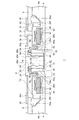
図2は、図1(a)のA−A線断面図である。回転機器1は、積層コア40と、コイル42と、をさらに備える。積層コア40は円環部とそこから半径方向(すなわち回転軸Rに直交する方向)外側に伸びる12本の突極とを有し、ベース4の上面4d側に固定される。積層コア40は、4枚の薄型電磁鋼板を積層しカシメにより一体化して形成される。積層コア40の表面には電着塗装や粉体塗装などによる絶縁塗装が施される。それぞれの突極にはコイル42が巻回される。このコイル42に3相の略正弦波状の駆動電流が流れることにより突極に沿って駆動磁束が発生する。ベース4の上面4dには、ロータ6の回転軸Rを中心とする円環状の環状壁部4eが設けられる。積層コア40は環状壁部4eの外周面4gに圧入されもしくは隙間ばめによって接着固定される。
FIG. 2 is a cross-sectional view taken along line AA in FIG. The
ベース4には、ロータ6の回転軸Rを中心とする貫通孔4hが設けられる。軸受ユニット12は、ハウジング44と、スリーブ46と、を含み、ロータ6をベース4に対して回転自在に支持する。ハウジング44はベース4の貫通孔4hに接着により固定される。ハウジング44は、円筒部と底部とが一体に形成された有底カップ形状を有し、その底部を下にしてベース4に対して接着固定される。
The
ハウジング44の外周面44aは銅合金にニッケルメッキを施して形成されるが、その外周面44aのうちハウジング44を貫通孔4hに接着するための接着剤と接触すべき領域の少なくとも一部ではニッケルメッキが除去される。言い換えると、ハウジング44の外周面44aは接着剤と接触する部分の少なくとも一部を除いてニッケルメッキの層を有する。例えば、ハウジング44の外周面44a全体をニッケルメッキした後、除去すべき部分のニッケルメッキを切削により除去することができる。この場合、ニッケルメッキを除去した部分で接着剤の結合力が向上し得る。
The outer
スリーブ46は、ハウジング44の内側の側面に接着により固定される円筒状の部材である。スリーブ46の上端には径方向外側に向けて張り出した張出部46aが形成されている。この張出部46aは、フランジ30と協働してロータ6の軸方向すなわち回転軸R方向の移動を制限する。
The
スリーブ46にはシャフト26が収まる。シャフト26およびハブ28およびフランジ30と軸受ユニット12との間の空間には潤滑剤48が注入される。
スリーブ46の内周面には、上下に離間した1組のヘリングボーン形状のラジアル動圧溝50が形成される。ハウジング44の上面に対向するフランジ30の下面には、ヘリングボーン形状の第1スラスト動圧溝(不図示)が形成される。張出部46aの下面に対向するフランジ30の上面には、ヘリングボーン形状の第2スラスト動圧溝(不図示)が形成される。ロータ6の回転時には、これらの動圧溝が潤滑剤48に生成する動圧によって、ロータ6は半径方向および回転軸R方向に支持される。
The
On the inner peripheral surface of the
なお、1組のヘリングボーン形状のラジアル動圧溝をシャフト26に形成してもよい。また、第1スラスト動圧溝をハウジング44の上面に形成してもよく、第2スラスト動圧溝を張出部46aの下面に形成してもよい。
A pair of herringbone-shaped radial dynamic pressure grooves may be formed in the
ロータ6は、シャフト26と、ハブ28と、フランジ30と、円筒状マグネット32と、を含む。ハブ28のディスク載置面28a上に磁気記録ディスク8が載置される。ハブ28の上面28bには3つのディスク固定用ねじ穴34がロータ6の回転軸Rの周りに120度間隔で設けられている。クランパ36は、3つのディスク固定用ねじ穴34に螺合される3つのディスク固定用ねじ38によってハブ28の上面28bに圧着されると共に磁気記録ディスク8をハブ28のディスク載置面28aに圧着させる。
The
ハブ28は、軟磁性を有する例えばSUS430F等の鉄鋼材料から形成される。ハブ28は、鉄鋼板を例えばプレス加工や切削加工することにより形成され、略カップ状の所定の形状に形成される。ハブ28の鉄鋼材料としては、例えば、大同特殊鋼株式会社が供給する商品名DHS1のステンレスはアウトガスが少なく、加工容易である点で好ましい。また、同様に同社が供給する商品名DHS2のステンレスはさらに耐食性が良好な点でより好ましい。
The
シャフト26は、ハブ28の中心に設けられた孔28cであってロータ6の回転軸Rと同軸に設けられた孔28cに圧入と接着とを併用した状態で固着される。フランジ30は円環形状を有し、フランジ30の断面は、逆L字形状を有する。フランジ30は、ハブ28の下垂部28dの内周面28eに接着により固定される。
The
円筒状マグネット32は、略カップ形状のハブ28の内側の円筒面に相当する円筒状内周面28fに接着固定される。円筒状マグネット32は、ネオジウム、鉄、ホウ素などの希土類材料によって形成され、積層コア40の12本の突極と径方向に対向する。円筒状マグネット32にはその周方向(回転軸Rを中心とし回転軸Rに垂直な円の接線方向)に16極の駆動用着磁が施される。円筒状マグネット32の表面には電着塗装やスプレー塗装などによる防錆処理が施される。
The
貫通孔4hの下側の縁には熱硬化型の導電性樹脂52がベース4からハウジング44にかけて塗布される。この導電性樹脂52は主成分としてエポキシ樹脂を含まない。例えば、金属などの導電性を有する材料を主成分とした導電性樹脂を使用してもよい。より具体的には、エポキシ樹脂以外の成分が80%以上含まれる導電性樹脂を使用してもよい。これにより、エポキシ樹脂の泳動によって生じうる、ベース4のコーティング領域の外観の劣化を抑えることができる。
A thermosetting
導電性を有する材料としては銀ペーストなどの種々の材料を用いることができる。例えば、ニッケルペーストは導電性の経時変化が少なく安価である点で好ましい。主成分としてエポキシ樹脂を含まない導電性樹脂としては種々のものを用いることができる。例えば、スリーボンド社製の製品番号3317は、ニッケルペーストを主成分としエポキシ樹脂を含まない導電性樹脂であって1液性であるため、2液混合のような手間がかからず塗布作業の機械化に有利である。 Various materials such as silver paste can be used as the conductive material. For example, nickel paste is preferable in that it is less expensive with little change in conductivity over time. Various conductive resins that do not contain an epoxy resin as a main component can be used. For example, product number 3317 manufactured by ThreeBond Co., Ltd. is a one-component conductive resin that contains nickel paste as a main component and does not contain an epoxy resin. Is advantageous.
(第1の実施の形態)
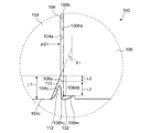
図3は、第1の実施の形態に係る回転機器100の断面のうち導電性樹脂102が塗布される部分を拡大して示す拡大断面図である。図3は図2の破線の円で囲まれる領域に対応する。
(First embodiment)
FIG. 3 is an enlarged cross-sectional view showing an enlarged portion to which the
回転機器100の軸受ユニットに含まれるハウジング104は、ベース106の貫通孔106hの周面106haと対向する円筒状の外周面104aと、その外周面104aの下側に設けられその外周面104aの直径D1よりも小さな直径を有するガイド面104bと、を含む。
The
ガイド面104bは、外周面104aの下端からハウジング104の底面104cに至るまで連続的に縮径する形状を有し、特に円錐面の一部となっている。ガイド面104bは、ガイド面104bが回転軸Rとなす角度θ1が10°から45°の範囲となるように形成される。この場合加工がより容易となる。ガイド面104bは、回転軸R方向に沿った長さL1が0.5mmから2mmの範囲の長さとなるように形成される。
The
ハウジング104と貫通孔106hとに連続的に介在する接着剤108は、ガイド面104bと貫通孔106hの周面106haとで挟まれる端部空間110に界面108aを有する。端部空間110は回転軸Rを中心とした環状の空間であり、その断面は略台形である。端部空間110のうちの残りの部分、すなわち接着剤108によって満たされている部分以外の部分、の少なくとも一部には、ガイド面104bから貫通孔106hの周面106haに亘って連続的に導電性樹脂102が塗布される。
The adhesive 108 continuously interposed between the
貫通孔106hの周面106haのうちガイド面104bと半径方向に対向する対向周面106hbについて、導電性樹脂102と接触する部分の回転軸R方向の長さL2は接着剤108と接触する部分の回転軸R方向の長さL3よりも長い。特に、対向周面106hbについて、導電性樹脂102と接触する部分の面積は5mm2から20mm2の範囲にある。
Of the peripheral surface 106ha of the through
ベース106には貫通孔106hの下側の周端106hcから半径方向外側に向けて切削した切削部106mが設けられる。導電性樹脂102は、ガイド面104b、界面108a、周面106ha、切削部106mの表面、のそれぞれに沿うように塗布される。導電性樹脂102の下側の端面には凹部112が設けられる。このような凹部112を設けない場合と比べて、凹部112を設けた場合凹部112の体積分導電性樹脂102の塗布量を削減できる。これにより回転機器100の総重量を低減できると共に、ひとつの回転機器100の製造に必要な導電性樹脂102の量を低減してコストを削減できる。
The
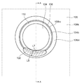
図4は、ベース106の下面106kのうち貫通孔106hの周端106hc付近を拡大して示す拡大下面図である。図4のA−A線は図2の断面に対応する。導電性樹脂102は端部空間110の一部を占め、特に貫通孔106hの周端106hcのうちの所定の長さL7の部分を覆うように塗布される。すなわち、導電性樹脂102の周方向における長さはL7である。
FIG. 4 is an enlarged bottom view showing the vicinity of the
導電性樹脂102は、導電性樹脂102の周方向における長さL7が導電性樹脂102の半径方向の幅L8の1.5倍以上となるように塗布される。これにより、導電性樹脂102そのものの耐衝撃性や導電性樹脂102とハウジング104やベース106との導通の耐衝撃性が向上しうる。
The
端部空間110の体積V1と接着剤108の体積V2との関係について説明する。
図5は、第1の実施の形態に係る回転機器100について、ベース106の貫通孔106hにハウジング104がガイド面104b側から挿入される前の状態を示す部分断面図である。貫通孔106hの周面106ha上方に一周に亘って接着剤108が塗布され、ハウジング104は貫通孔106hに上から挿入される。
The relationship between the volume V1 of the
FIG. 5 is a partial cross-sectional view showing a state before the
ガイド面104bの回転軸R方向の長さL1は、貫通孔106hの周面106haの直径D4とガイド面104bの最小直径D3(すなわち、ガイド面104bの下側の周端の直径)との差の2分の1である半径差uより大きい。また、端部空間110の体積V1は接着剤108の体積V2の66%から200%の範囲とされる。
The length L1 of the
本実施の形態に係る回転機器100によると、接着剤108と導電性樹脂102とが共存する端部空間110を形成するためにガイド面104bがテーパ状とされる。端部空間110に接着剤108がまったくないとハウジング104とベース106との接着強度が十分に得られない可能性がある。また、ハウジング104の外周面104aと貫通孔106hの周面106haとの隙間において接着剤108によって埋められない部分ができると、接着強度の点でさらに好ましくない。したがって、ハウジング104が挿入された後の端部空間110はある程度の接着剤108を有する。言い換えると、回転機器100の設計上の寸法等から塗布すべき接着剤108の量として、ハウジング104の外周面104aと貫通孔106hの周面106haとの隙間を満たして端部空間110に少しはみ出る程度の量が算出され、その量の接着剤108が実際に塗布される。これにより、隙間の体積や塗布量が設計値からばらついても隙間において接着剤108によって埋められれない部分が発生する可能性が低減される。
また、端部空間110の大部分が接着剤108で占められてしまうと、導電性樹脂102とハウジング104、ベース106との接触面積が減少して、ハウジング104とベース106との間の導通確保の点で難が生じうる。したがって、対向周面106hbについて、導電性樹脂102と接触する部分の回転軸R方向の長さL2は接着剤108と接触する部分の回転軸R方向の長さL3よりも長い。これにより、端部空間110に入り込んだ接着剤の分だけハウジング104とベース106との接着強度を確保しつつ、導電性樹脂102とガイド面104bとの接触面積および導電性樹脂102と周面106haとの接触面積を稼ぐことができる。その結果、回転機器100が衝撃を受けた場合でも、ハウジング104とベース106との接着固定はダメージを受けにくく、かつ、導電性樹脂102はガイド面104bや周面106haから剥がれにくくなる。
According to the
In addition, when most of the
また、導電性樹脂102は、金属部分が露出された切削部106mの表面とも接触しているので、導電性樹脂102とベース106との導通はより確かなものとされる。さらに、切削部106mにおいて、塗布される導電性樹脂102の回転軸R方向の高さを切削深さ以下にしてもよい。塗布後の導電性樹脂102が製造設備などに触れて汚染する可能性が低くなる。
Further, since the
ガイド面104bの回転軸R方向の長さL1について、その長さL1が短すぎると、回転機器100が所定の試験衝撃加速度を受けた際に導電性樹脂102とハウジング104との接触を維持できない虞がある。そこで、本実施の形態に係る回転機器100では、ガイド面104bの回転軸R方向の長さL1を0.5mm以上とすることで導電性樹脂102とハウジング104との接触の耐衝撃性を確保している。
If the length L1 of the
また、ガイド面104bの回転軸R方向の長さL1が長すぎると、回転機器100はその分厚くなりうる。そこで、本実施の形態に係る回転機器100では、ガイド面104bの回転軸R方向の長さL1を2mm以下とすることで回転機器100の厚みの増大を抑えている。
特に、ガイド面104bの回転軸R方向の長さL1を0.7mm〜1.5mmの範囲とすると、回転機器の大型化を押さえつつ導電性樹脂102を介した導通の耐衝撃性をより維持しやすくなるのでより好適である。
If the length L1 of the
In particular, when the length L1 of the
対向周面106hbのうち導電性樹脂102と接触する部分の面積について、その面積が小さすぎると所定の試験衝撃加速度を受けた際に導電性樹脂102とベース106との接触を維持できない虞がある。そこで、本実施の形態に係る回転機器100では、対向周面106hbのうち導電性樹脂102と接触する部分の面積を5mm2以上とすることで導電性樹脂102とベース106との接触の耐衝撃性を確保している。
Regarding the area of the portion of the opposed peripheral surface 106hb that contacts the
また、対向周面106hbのうち導電性樹脂102と接触する部分の面積が大きすぎると、回転機器100はその分厚くなりうる。そこで、本実施の形態に係る回転機器100では、対向周面106hbのうち導電性樹脂102と接触する部分の面積を20mm2以下とすることで回転機器100の厚みの増大を抑えている。
特に、対向周面106hbのうち導電性樹脂102と接触する部分の面積を7mm2〜13mm2の範囲とすると、回転機器の大型化を押さえつつ導電性樹脂102を介した導通の耐衝撃性をより維持しやすくなるのでより好適である。
Moreover, if the area of the part which contacts the
In particular, if the area of the portion in contact with the
また、本実施の形態に係る回転機器100では、貫通孔106hの下側の周端106hc付近に切削部106mが設けられ、導電性樹脂102はこの切削部106mにも塗布される。したがって、切削部106mの切削深さ分だけ導電性樹脂102を厚く塗布できる。これにより、回転機器100が衝撃を受けた場合でも導電性樹脂102にクラックが発生しにくくなる。
In
端部空間110の体積V1が大きいと、ハウジング104を貫通孔106hに挿入する際、貫通孔106hの周面106haに塗布された接着剤108の大半は端部空間110に捕えられ、ガイド面104bに当たる。ガイド面104bがベース106に対して相対的に移動すると、ガイド面104bは接着剤108を貫通孔106hの周面106haに押しつけるように作用する。その結果、接着剤108はより円滑にベース106とハウジング104との間に浸透する。
When the volume V1 of the
また、ガイド面104bは下向きに縮径していくテーパ状となっているので、ガイド面104bが設けられていない場合と比較して、ハウジング104が挿入される際の接着剤108全体を回転軸R方向下側に向けて押し出そうとする力は小さくなる。したがって、接着剤108が引きちぎられて接着剤108に回転軸R方向の分断が生じる可能性を低減できる。つまり、ハウジング104挿入の際、より多くの接着剤108が端部空間110に集められるので、ハウジング104の底面104cに押しのけられる接着剤108はないか、あっても微量である。
Further, since the
端部空間110の体積V1が接着剤108の体積V2に対して小さすぎると、接着剤108は端部空間110内に収まりきらず、ハウジング104の底面104cに押し出される割合が増えうる。端部空間110の体積V1が接着剤108の体積V2の66%以上である場合には、ハウジング104の挿入中、接着剤108はほぼ端部空間110内に収まると考えられる。
If the volume V <b> 1 of the
また、端部空間110の体積V1が接着剤108の体積V2に対して小さすぎると、接着剤108のうちガイド面104bによって貫通孔106hの周面106haに押しつけられる部分の割合が小さくなる。するとハウジング104とベース106との間に浸透した接着剤108に分断が生じる可能性が高まる。端部空間110の体積V1が接着剤108の体積V2の2/3である66%以上である場合には、有意に接着剤108の分断を減らすことができると考えられる。
If the volume V1 of the
端部空間110の体積V1が接着剤108の体積V2に対して大きすぎると、ガイド面104bの回転軸R方向の長さL1が長くなり、回転機器をその分大きくする必要がある。あるいはまた、回転機器の大きさを一定に保ちつつ長さL1を長くすると、その分だけ軸受ユニットの回転軸R方向の長さを短くすることとなり、軸受の剛性が低下し、ハブの回転精度が低下する可能性がある。端部空間110の体積V1が接着剤108の体積V2の2倍である200%以下である場合にはそのような影響は大きくないと考えられる。
If the volume V1 of the
ハウジング104を挿入する際、接着剤108が概ねガイド面104bに当たるための半径差uの条件について考察する。
ハウジング104を挿入する前に貫通孔106hの周面106ha上方に一周に亘って塗布された接着剤108の断面を、長径/短径比が2の半楕円で近似する。この半楕円の短径を2Hとし、貫通孔106hの周面106haの直径D4は短径2Hよりも十分大きいとした場合、接着剤108の体積V2は以下の式1で表される。

The cross section of the adhesive 108 applied over the entire circumference 106ha of the through-
(第2の実施の形態)
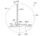
図6は、第2の実施の形態に係る回転機器200の断面のうち導電性樹脂202が塗布される部分を拡大して示す拡大断面図である。図6は図2の破線の円で囲まれる領域に対応する。
(Second Embodiment)
FIG. 6 is an enlarged cross-sectional view showing an enlarged portion to which the
回転機器200の軸受ユニットに含まれるハウジング204は、ベース206の貫通孔206hの周面206haと対向する円筒状の外周面204aと、その外周面204aの下側に設けられその外周面204aの直径D2よりも小さな直径を有するガイド面204bと、を含む。
The
ガイド面204bは、外周面204aの下端からハウジング204の底面204cに至るまで、後述の環状凹部210を除いて連続的に縮径する形状を有する。ガイド面204bは、そのガイド面204bが回転軸Rとなす角度θ2が10°から45°の範囲となるように形成される。この場合、加工がより容易となる。
The
ガイド面204bの回転軸R方向の途中には、回転軸Rを中心として環状に環状凹部210が設けられる。ハウジング204と貫通孔206hとに連続的に介在する接着剤208は、環状凹部210の少なくとも一部、本実施の形態では全部、を満たす。
In the middle of the
ベース206には貫通孔206hの下側の周端206hcから半径方向外側に向けて切削した切削部206mが設けられる。切削部206mは、回転軸Rを中心としたディスク形状を有し回転軸Rと略直交する切削面206maと、円筒状の側面206mbと、を有する。接着剤208は切削面206maの少なくとも一部を覆うように塗布される。すなわち、接着剤208は貫通孔206hの周面206haの下側の周端206hcよりも半径方向外側に拡がっている。
The
導電性樹脂202は、ベース206の下面の一部である切削面206maからガイド面204bに亘って連続的に塗布される。特に導電性樹脂202は、ガイド面204b、接着剤208の界面208a、切削面206ma、のそれぞれに沿うように塗布される。第1の実施の形態に係る回転機器100と同様に、回転機器200を下から見た場合に、導電性樹脂202は貫通孔206hの周端206hcのうちの所定の長さの部分を覆うように塗布される。
The
環状凹部210および切削部206mは、貫通孔206hの周面206haの下側の周端206hcが環状凹部210と半径方向に対向するように形成される。特に回転軸R方向において、環状凹部210と貫通孔206hの周面206haの下側の周端206hcとは位置が揃っている。
The
本実施の形態に係る回転機器200によると、接着剤208は環状凹部210の少なくとも一部を満たすと共に、貫通孔206hの周面206haの下側の周端206hcよりも半径方向外側に拡がっている。したがって接着剤208は環状凹部210に食い込んでいるので、回転機器200が衝撃を受けた場合でも、その食い込んだ部分が環状凹部210から受ける回転軸R方向の力によって接着剤208は下側に隆起しにくくなる。さらに、接着剤208は周端206hcを覆っているので導電性樹脂202は角部である周端206hcに接しない。これらの結果、導電性樹脂202に加わる応力を分散させることができ、衝撃によって導電性樹脂202にクラックが生じる可能性を低減できる。
According to the
周端206hcよりも環状凹部を下側に設けると、環状凹部の少なくとも一部に接着剤を入れる都合上接着剤の界面がよりハウジング204の底面204cに近づく。すると、導電性樹脂をベース206の下面からはみ出さないように塗布することが難しくなる。
また、周端206hcよりも環状凹部を上側に設けると、接着剤を切削面206maにも接触させる都合上接着剤の界面と環状凹部との回転軸R方向における距離が大きくなりうる。すると、環状凹部による接着剤の隆起規制効果は小さくなりうる。
したがって、本実施の形態に係る回転機器200では、所望の量の導電性樹脂202をベース206の下面からはみ出さないように塗布可能としつつ所望の接着剤208の隆起規制効果を得ることができるよう、貫通孔206hの周面206haの下側の周端206hcは環状凹部210と半径方向に対向する。
When the annular recess is provided below the peripheral end 206hc, the interface of the adhesive is closer to the
If the annular recess is provided on the upper side of the peripheral end 206hc, the distance between the interface of the adhesive and the annular recess in the direction of the rotation axis R can be increased for the purpose of bringing the adhesive into contact with the cutting surface 206ma. As a result, the effect of restricting the protrusion of the adhesive by the annular recess can be reduced.
Therefore, in the
環状凹部210の形状を、所定の試験衝撃加速度を受けた場合でもハウジング204とベース206との間の電気抵抗が所定値以下に維持されるように実験により定めてもよい。例えば、本発明者らによる実験によると、環状凹部210の間口を0.1mm〜0.3mm、奥行きを0.1mm〜0.3mmとした場合、所定の試験衝撃加速度を受けた際にも導電性樹脂にクラックは発生しなかった。
The shape of the
図7は、第2の実施の形態の変形例に係る回転機器250の断面のうち導電性樹脂252が塗布される部分を拡大して示す拡大断面図である。図7は図2の破線の円で囲まれる領域に対応する。
FIG. 7 is an enlarged cross-sectional view showing an enlarged portion to which the
ハウジング254のガイド面254bは、回転軸Rを中心とした環状の環状凹部260と、環状凹部260の下側に設けられた回転軸Rを中心とした環状の環状凸部262と、を有する。環状凸部262は環状凹部260を庇状に覆っている。環状凹部260および環状凸部262は、所定の試験衝撃加速度を受けた場合でもハウジング254とベース206との間の電気抵抗が所定値以下に維持される形状を有する。
The
ハウジング254と貫通孔206hとに連続的に介在する接着剤258は、環状凹部260の全部を満たすと共に、環状凸部262の一部を覆う。接着剤258は貫通孔206hの周面206haの下側の周端206hcよりも半径方向外側に拡がっている。
導電性樹脂252は、切削面206maからガイド面254bに亘って連続的に塗布される。
環状凹部260および切削部206mは、貫通孔206hの周面206haの下側の周端206hcが環状凹部260と半径方向に対向するように形成される。
The adhesive 258 continuously interposed between the
The
The
本変形例によると、第2の実施の形態に係る回転機器200によって奏される作用効果に加えて以下の作用効果が奏される。
本変形例に係る回転機器250によると、接着剤258が環状凹部260と環状凸部262の両方から受ける回転軸R方向の力によって接着剤258は下側により隆起しにくくなる。その結果、導電性樹脂252に加わる応力を分散させることができ、衝撃によって導電性樹脂252にクラックが生じる可能性をより低減できる。
According to this modification, in addition to the operational effects achieved by the
According to the
(製造方法)
第1の実施の形態に係る回転機器100の製造方法の一例を説明する。第2の実施の形態に係る回転機器200やその変形例に係る回転機器250も同様の製造方法で製造できることは、本明細書に触れた当業者には明らかである。
(Production method)
An example of a method for manufacturing the
ロータ6、スリーブ46およびハウジング104を含むハブユニットを組み立てる。また、別途ベース106、積層コア40およびコイル42を含むベースユニットを組み立てる。
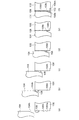
図8(a)〜(f)は、ハブユニットをベースユニットに取り付ける際の様子を示す部分断面図である。
A hub unit including the
FIGS. 8A to 8F are partial cross-sectional views illustrating a state when the hub unit is attached to the base unit.
図8(a)はベース106の貫通孔106hにハウジング104がガイド面104b側から挿入される前の状態を示す部分断面図であり、図5に対応する。ハウジング104の挿入前に、貫通孔106hの周面106ha上方に周状に接着剤108が塗布される。ハウジング104は貫通孔106hにガイド面104bを先にして挿入される。図8(b)は接着剤108がガイド面104bに接触するときの状態を示す部分断面図である。本製造方法では、ハウジング104の挿入の際、接着剤108はハブユニットのなかではまずガイド面104bに接触する。
FIG. 8A is a partial cross-sectional view showing a state before the
その後、図8(c)、(d)、(e)に示されるように接着剤108をハウジング104とベース106との間に浸透させるように徐々にハウジング104を貫通孔106hに挿入し、所定の位置で挿入を止める。この挿入の際、ガイド面104bによって接着剤108は貫通孔106hの周面106haに押しつけられるようにしてハウジング104とベース106との間に浸透する。
Thereafter, as shown in FIGS. 8C, 8D, and 8E, the
なお、この挿入の際、ガイド面104bが接着剤108に接触した後、ガイド面104bが接着剤108に接触した状態でハウジング104をベース106に対して周方向に動かしてもよい、すなわち回転させてもよい。あるいはまた、この挿入の際、ガイド面104bが接着剤108に接触した後、ガイド面104bが接着剤108に接触した状態でハウジング104をベース106に対して回転軸R方向に往復運動させてもよい。あるいはまた、ガイド面104bが接着剤108に接触した後、ガイド面104bが接着剤108に接触した状態でハウジング104を半回転させ、そのまま戻さないでその位置で貫通孔106hに挿入してもよい。これらの場合、接着剤108が均されるのでハウジング104とベース106との間における接着剤108の分布のムラが軽減され、接着剤108の分断の発生が抑えられる。
In this insertion, after the
ハウジング104が所定の位置まで挿入されると、接着剤108は所定の硬化の度合いまで硬化される。これによりハウジング104はベース106に仮固着される。所定の硬化の度合いは、接着剤108について予め定められている硬化の条件を満たす硬化によって得られる接着強度よりも低い接着強度を実現する硬化の度合いであり、例えば重力によってハウジング104とベース106との位置関係がずれなくなる程度の硬化の度合いである。接着剤108が紫外線硬化型の接着剤である場合は、接着剤108に適量の紫外線が照射されハウジング104とベース106とが仮固着される。
なお、接着剤108の界面は、図3に示されるように回転軸Rにほぼ直交するような界面108aであってもよく、図8(e)、(f)に示されるように少し斜めの界面108bであってもよい。
When the
Note that the interface of the adhesive 108 may be an
図8(f)は、導電性樹脂102が塗布された状態を示す部分断面図である。仮固着の後、ハウジング104のガイド面104bからベース106の切削部106mに亘って連続的に導電性樹脂102が塗布される。そのように塗布された導電性樹脂102は熱処理によって硬化される。接着剤108が熱硬化型である場合には、導電性樹脂102の熱処理に合わせて接着剤108が仮固着の状態からさらに硬化されてもよい。熱処理としては例えば導電性樹脂102を塗布した後のハブユニットおよびベースユニットを高温雰囲気中に所定時間静置することがある。
FIG. 8F is a partial cross-sectional view showing a state where the
導電性樹脂102が硬化された後、ベース106の一方の側と他方の側との間のリークの有無が検査される。特に、貫通孔106hからのリークの有無が検査される。この検査では、ベース106の一方の面を含んで画成され、その面からのリークが無ければ密閉されている空間を大気圧よりも高い圧力とし、その空間の圧力の低下の速度を測定する。この場合、回転機器100の製造の一連の流れの中でリーク検査まで行うことができるので好適である。
After the
ハウジング104が貫通孔106hに挿入される前に貫通孔106hの周面106haに塗布される接着剤108の量は、挿入の際接着剤108がハブユニットのなかではまずガイド面104bに接触するような量としている。特に、ハウジング104の挿入前において、回転軸Rを含む断面で見たときの接着剤108の半径方向の高さの最大値を、周方向で平均した平均値hは以下の式4を満たす。
図9(a)〜(f)は、比較例に係る回転機器について、ハブユニットをベースユニットに取り付ける際の様子を示す部分断面図である。図9(a)はベース506の貫通孔506hにハウジング504が挿入される前の状態を示す部分断面図である。接着剤508は貫通孔506hの周面に周状に塗布される。次に、ハウジング504が貫通孔506hの上側から挿入される(図9(b))。さらに、ハウジング504が貫通孔506hの奥に向かって挿入される。この際、ハウジング504を押す力は接着剤508に対して回転軸方向下側に働き、半径方向で貫通孔506hの周面に向かう向きには殆ど働かない。つまり、接着剤508の全体には回転軸方向下側向きの力が働く。接着剤508のうち貫通孔506hの周面の近傍に存在する部分にのみその周面に残ろうとする粘着力(あるいは摩擦力)が働く。
FIGS. 9A to 9F are partial cross-sectional views showing a state when the hub unit is attached to the base unit in the rotating device according to the comparative example. FIG. 9A is a partial cross-sectional view showing a state before the
その結果、塗布された接着剤508の大部分はハウジング504の底面に押し出されてベース506の下面側に移動する。塗布された接着剤508のうち一部がその粘着力により貫通孔506hの周面に随伴してハウジング504とベース506との間に残るに過ぎないので、そのようにして残る接着剤の割合は小さい(図9(c))。ハウジング504が貫通孔506hの奥に向かってさらに挿入される。この際、接着剤508は回転軸方向下側に引っ張られる力により引きちぎられて回転軸方向の途中で容易に分断される(図9(d))。ハウジング504が所定の位置まで挿入される。この際、接着剤508は回転軸方向でさらに分断される(図9(e))。このような接着剤508の分断は周方向に均等に生じることは少なく、ランダムに生じる場合が多い。このため、全体として周方向にも分断を生じやすい。接着剤508が硬化された後導電性樹脂502がその上から塗布されるが、塗布された導電性樹脂502はベース506の下面から盛り上がる(図9(f))。
As a result, most of the applied adhesive 508 is pushed out to the bottom surface of the
図10(a)、(b)は、ハウジングとベースとの間での接着剤の分布の様子を示す説明図である。図10(a)は、比較例に係る回転機器について、貫通孔506hの周面506haに付着する接着剤508の分布の様子を示す説明図である。図10(a)は、貫通孔506hを回転軸に沿った面で2分割し、その一方を斜め上方から見た図である。図10(a)に示されるように、比較例に係る回転機器では、接着剤508の分布には回転軸方向にも周方向にも多くのムラがあり、接着剤508は多くの箇所で分断されている。したがって、この分断された部分がつながってリークの経路を形成する可能性がある。
FIGS. 10A and 10B are explanatory views showing the state of distribution of the adhesive between the housing and the base. Fig.10 (a) is explanatory drawing which shows the mode of distribution of the
これに対して第1の実施の形態に係る回転機器100の製造方法では、ハウジング104の挿入の際、ガイド面104bが接着剤108を貫通孔106hの周面106haに押しつける。したがって、ハウジング104とベース106との間の接着剤108の分断は抑えられ、よりリークタイトな回転機器が実現される。図10(b)は、第1の実施の形態に係る回転機器100について、貫通孔106hの周面106haに付着する接着剤108の分布の様子を示す説明図である。図10(b)は、貫通孔106hを回転軸Rに沿った面で2分割し、その一方を斜め上方から見た図である。貫通孔106hの周面106ha上には接着剤108がより均一にムラなく分布している。部分56は、接着剤108が存在しない部分56である。
On the other hand, in the manufacturing method of the
回転機器100では、接着剤108を接着剤108が一周に亘って分断がなく連続的に存在する連続層108cとそうでない非連続層108dとに分けるとき、連続層108cの回転軸R方向の長さL4、L6の合計(L4+L6)は非連続層108dの回転軸R方向の長さL5の合計(L5)よりも大きい。その結果、リークの発生が抑えられる。
In the
ハウジング104の底面104cに接着剤108が付着すると、製造工程における治具、工具や設備にその接着剤が付着する虞がある。またそのような接着剤を除去するには手間がかかり、除去せずに残しておくと回転機器の外観の品位を損ねかねない。この点について本製造方法では、ハウジング104の底面104cに接着剤108は付着しないか、したとしても微量、例えばガイド面104bに付着している量よりも少ない量、である。したがって、回転機器100製造のための治具、工具に接着剤108が付着する可能性を低減でき、外観の品位を保ちうる。
If the adhesive 108 adheres to the
なお、ハウジング104が貫通孔106hに挿入される前に、貫通孔106hの周面106haに接着剤を回転軸R方向で複数箇所塗布してもよい。すなわち、接着剤を貫通孔106hの周面106haの回転軸R方向に離間した位置に分けて塗布してもよい。
Note that, before the
以上、実施の形態に係る回転機器の構成と動作およびそのような回転機器の製造方法について説明した。これらの実施の形態は例示であり、それらの各構成要素の組み合わせにいろいろな変形例が可能なこと、またそうした変形例も本発明の範囲にあることは当業者に理解されるところである。あるいはまた、実施の形態同士の組み合わせも可能である。例えば、第1の実施の形態に係る回転機器100のガイド面104bに、第2の実施の形態に係る回転機器200の環状凹部210と同様の環状凹部を設けてもよい。
The configuration and operation of the rotating device according to the embodiment and the method for manufacturing such a rotating device have been described above. It is to be understood by those skilled in the art that these embodiments are exemplifications, and that various modifications can be made to combinations of the respective components, and such modifications are within the scope of the present invention. Alternatively, the embodiments can be combined. For example, an annular recess similar to the
第1および第2の実施の形態では、円筒状マグネット32が積層コア40の外側に位置する、いわゆるアウターロータ型の回転機器について説明したが、これに限られない。たとえば円筒状マグネットが積層コアの内側に位置する、いわゆるインナーロータ型のディスク駆動装置であってもよい。
In the first and second embodiments, the so-called outer rotor type rotating device in which the
第1および第2の実施の形態では、軸受ユニットがベースに固定され、シャフトが軸受ユニットに対して回転する場合について説明したが、たとえばシャフトがベースに固定され、軸受ユニットがハブと共にシャフトに対して回転するようなシャフト固定型であってもよい。この場合、シャフトとベースとは別体で形成され、シャフトをベースに設けられた孔に挿入して接着固定する際に、第1または第2の実施の形態に係る技術的思想を適用できる。 In the first and second embodiments, the case where the bearing unit is fixed to the base and the shaft rotates relative to the bearing unit has been described. For example, the shaft is fixed to the base, and the bearing unit is attached to the shaft together with the hub. It may be a fixed shaft type that rotates. In this case, the shaft and the base are formed separately, and the technical idea according to the first or second embodiment can be applied when the shaft is inserted into a hole provided in the base and fixed.
第1および第2の実施の形態では、ベースに直接軸受ユニットが取り付けられる場合について説明したが、これに限られない。例えば、ロータ、軸受ユニット、積層コア、コイルおよびベースからなるブラシレスモータを別途形成した上で、そのブラシレスモータをシャーシに取り付ける構成としてもよい。 In the first and second embodiments, the case where the bearing unit is directly attached to the base has been described, but the present invention is not limited to this. For example, a brushless motor including a rotor, a bearing unit, a laminated core, a coil, and a base may be separately formed, and the brushless motor may be attached to the chassis.
第1および第2の実施の形態では積層コアを用いる場合について説明したが、コアは積層コアでなくてもよい。 In the first and second embodiments, the case where a laminated core is used has been described, but the core may not be a laminated core.
第1の実施の形態では、ガイド面104bはハウジング104の表面に形成される場合について説明したが、これに限られず、ハウジングの底面にガイド面を側面として有するガイド部材を接着等により固定するなど、ハウジングとは異なる部材にガイド面を設けてもよい。
In the first embodiment, the case where the
第1および第2の実施の形態において、導電性樹脂を塗布した領域を製造情報を表示するシールで覆ってもよい。特にこのシールは貫通孔を塞ぎ、導電性樹脂102を塗布した領域および貫通孔とハウジングとの接着部を覆ってもよい。この場合、導電性樹脂102および接着部を保護することができる。
In the first and second embodiments, the region to which the conductive resin is applied may be covered with a seal that displays manufacturing information. In particular, this seal may block the through hole and cover the region where the
100 回転機器、 102 導電性樹脂、 104b ガイド面、 106 ベース、 106h 貫通孔、 106ha 周面、 106hc 周端、 108 接着剤、 110 端部空間、 112 凹部、 200 回転機器、 202 導電性樹脂、 204b ガイド面、 206 ベース、 206h 貫通孔、 206ha 周面、 206hc 周端、 208 接着剤、 210 環状凹部、 250 回転機器。 100 rotating device, 102 conductive resin, 104b guide surface, 106 base, 106h through hole, 106ha peripheral surface, 106hc peripheral end, 108 adhesive, 110 end space, 112 recess, 200 rotating device, 202 conductive resin, 204b Guide surface, 206 base, 206h through hole, 206ha peripheral surface, 206hc peripheral end, 208 adhesive, 210 annular recess, 250 rotating device.
Claims (20)
前記ハブを回転自在に支持する軸受ユニットと、
貫通孔が設けられ、当該貫通孔に前記軸受ユニットが接着固定されるベースと、を備え、
前記軸受ユニットは、前記貫通孔の周面と対向する円筒状の外周面と、前記外周面の前記ハブとは反対側に設けられ前記外周面の直径よりも小さな直径を有するガイド面と、を含み、
前記軸受ユニットと前記貫通孔とに介在する接着剤は、前記ガイド面と前記貫通孔の周面とで挟まれる端部空間に界面を有し、
前記端部空間のうちの残りの部分の少なくとも一部には前記ガイド面から前記貫通孔の周面に亘って連続的に導電性樹脂が塗布され、
前記貫通孔の周面のうち前記ガイド面と半径方向に対向する部分について、前記導電性樹脂と接触する部分の軸方向の長さは前記接着剤と接触する部分の軸方向の長さよりも長いことを特徴とする回転機器。 A hub on which the recording disk should be placed;
A bearing unit that rotatably supports the hub;
A through hole is provided, and a base to which the bearing unit is bonded and fixed to the through hole.
The bearing unit includes a cylindrical outer peripheral surface facing the peripheral surface of the through hole, and a guide surface that is provided on the opposite side of the outer peripheral surface from the hub and has a diameter smaller than the diameter of the outer peripheral surface. Including
The adhesive interposed between the bearing unit and the through hole has an interface in an end space sandwiched between the guide surface and the peripheral surface of the through hole,
A conductive resin is continuously applied from the guide surface to the peripheral surface of the through hole on at least a part of the remaining portion of the end space,
Of the peripheral surface of the through-hole, the length of the portion facing the guide surface in the radial direction is longer than the length of the portion in contact with the adhesive in the axial direction. Rotating equipment characterized by that.
前記ハブを回転自在に支持する軸受ユニットと、
貫通孔が設けられ、当該貫通孔に前記軸受ユニットが接着固定されるベースと、を備え、
前記軸受ユニットは、前記貫通孔の周面と対向する円筒状の外周面と、前記外周面の前記ハブとは反対側に設けられ前記外周面の直径よりも小さな直径を有するガイド面と、を含み、
前記ガイド面には凹部が設けられ、
前記軸受ユニットと前記貫通孔とに介在する接着剤は、前記凹部の少なくとも一部を満たすと共に、前記貫通孔の周面の前記ハブとは反対側の周端よりも半径方向外側に拡がっており、
前記ベースの前記ハブとは反対側の表面から前記ガイド面に亘って連続的に導電性樹脂が塗布されることを特徴とする回転機器。 A hub on which the recording disk should be placed;
A bearing unit that rotatably supports the hub;
A through hole is provided, and a base to which the bearing unit is bonded and fixed to the through hole.
The bearing unit includes a cylindrical outer peripheral surface facing the peripheral surface of the through hole, and a guide surface that is provided on the opposite side of the outer peripheral surface from the hub and has a diameter smaller than the diameter of the outer peripheral surface. Including
The guide surface is provided with a recess,
The adhesive interposed in the bearing unit and the through hole fills at least a part of the recess and extends radially outward from the peripheral end of the peripheral surface of the through hole opposite to the hub. ,
A rotating device, wherein a conductive resin is continuously applied from a surface of the base opposite to the hub to the guide surface.
前記ハブを回転自在に支持する軸受ユニットと、
貫通孔が設けられ、当該貫通孔に前記軸受ユニットが接着固定されるベースと、を備え、
前記軸受ユニットは、前記貫通孔の周面と対向する円筒状の外周面と、前記外周面の前記ハブとは反対側に設けられ前記外周面の直径よりも小さな直径を有するガイド面と、を含み、
前記軸受ユニットと前記貫通孔とに介在する接着剤は、前記ガイド面と前記貫通孔の周面とで挟まれる端部空間に界面を有し、
前記端部空間のうちの残りの部分の少なくとも一部には前記ガイド面から前記貫通孔の周面に亘って連続的に導電性樹脂が塗布され、
前記端部空間の体積は前記接着剤の体積の66%から200%の範囲とされることを特徴とする回転機器。 A hub on which the recording disk should be placed;
A bearing unit that rotatably supports the hub;
A through hole is provided, and a base to which the bearing unit is bonded and fixed to the through hole.
The bearing unit includes a cylindrical outer peripheral surface facing the peripheral surface of the through hole, and a guide surface that is provided on the opposite side of the outer peripheral surface from the hub and has a diameter smaller than the diameter of the outer peripheral surface. Including
The adhesive interposed between the bearing unit and the through hole has an interface in an end space sandwiched between the guide surface and the peripheral surface of the through hole,
A conductive resin is continuously applied from the guide surface to the peripheral surface of the through hole on at least a part of the remaining portion of the end space,
The rotary device according to claim 1, wherein a volume of the end space is in a range of 66% to 200% of a volume of the adhesive.
前記軸受ユニットの外周面は、前記接着剤と接触する部分の少なくとも一部を除いてニッケルメッキの層を有することを特徴とする請求項1から13のいずれかに記載の回転機器。 The base is formed of an aluminum alloy;
14. The rotating device according to claim 1, wherein an outer peripheral surface of the bearing unit has a nickel-plated layer except for at least a part of a portion in contact with the adhesive.
前記貫通孔の周面に接着剤を周状に塗布するステップと、
前記貫通孔に前記軸受ユニットを、前記軸受ユニットの前記ガイド面を先にして挿入するステップと、
周状に塗布された接着剤を所定の硬化の度合いまで硬化させることで前記軸受ユニットを前記ベースに仮固着するステップと、
前記軸受ユニットから前記ベースに亘って連続的に導電性樹脂を塗布するステップと、
少なくとも塗布された導電性樹脂を熱処理によって硬化させるステップと、を含むことを特徴とする方法。 A method for manufacturing the rotating device according to any one of claims 1 to 14,
Applying an adhesive circumferentially to the peripheral surface of the through hole;
Inserting the bearing unit into the through hole with the guide surface of the bearing unit first;
Temporarily fixing the bearing unit to the base by curing a circumferentially applied adhesive to a predetermined degree of curing;
Applying conductive resin continuously from the bearing unit to the base;
Curing at least the applied conductive resin by heat treatment.
Priority Applications (2)
| Application Number | Priority Date | Filing Date | Title |
|---|---|---|---|
| JP2011003093A JP2012145157A (en) | 2011-01-11 | 2011-01-11 | Rotating device and method for manufacturing the rotating device |
| US13/335,513 US8638526B2 (en) | 2011-01-11 | 2011-12-22 | Rotating device |
Applications Claiming Priority (1)
| Application Number | Priority Date | Filing Date | Title |
|---|---|---|---|
| JP2011003093A JP2012145157A (en) | 2011-01-11 | 2011-01-11 | Rotating device and method for manufacturing the rotating device |
Publications (1)
| Publication Number | Publication Date |
|---|---|
| JP2012145157A true JP2012145157A (en) | 2012-08-02 |
Family
ID=46455048
Family Applications (1)
| Application Number | Title | Priority Date | Filing Date |
|---|---|---|---|
| JP2011003093A Pending JP2012145157A (en) | 2011-01-11 | 2011-01-11 | Rotating device and method for manufacturing the rotating device |
Country Status (2)
| Country | Link |
|---|---|
| US (1) | US8638526B2 (en) |
| JP (1) | JP2012145157A (en) |
Cited By (1)
| Publication number | Priority date | Publication date | Assignee | Title |
|---|---|---|---|---|
| JP2017027644A (en) * | 2015-07-24 | 2017-02-02 | 日本電産株式会社 | Spindle motor and disk drive device |
Families Citing this family (10)
| Publication number | Priority date | Publication date | Assignee | Title |
|---|---|---|---|---|
| GB2467967B (en) | 2009-02-24 | 2015-04-22 | Dyson Technology Ltd | Rotor assembly |
| JP2012145157A (en) * | 2011-01-11 | 2012-08-02 | Alphana Technology Co Ltd | Rotating device and method for manufacturing the rotating device |
| GB2487921B (en) * | 2011-02-08 | 2013-06-12 | Dyson Technology Ltd | Rotor for a turbomachine |
| US8873198B1 (en) * | 2011-09-30 | 2014-10-28 | Nidec Corporation | Motor and disk drive apparatus |
| US8824097B2 (en) * | 2011-09-30 | 2014-09-02 | Nidec Corporation | Motor and disk drive apparatus |
| CN104728133B (en) * | 2013-12-20 | 2019-12-10 | 日本电产株式会社 | fan with cooling device |
| US9721608B2 (en) * | 2015-03-13 | 2017-08-01 | Nidec Corporation | Spindle motor and disk drive apparatus |
| JP2017028895A (en) * | 2015-07-24 | 2017-02-02 | 日本電産株式会社 | Spindle motor and disk drive |
| CN107299954A (en) * | 2017-06-27 | 2017-10-27 | 北京航空航天大学 | The semi-active type bump leveller that a kind of mechanical adjustment is combined with Electromagnetic Control |
| CN113067972B (en) * | 2021-03-12 | 2023-04-18 | 新思考电机有限公司 | Shell assembly, driving device, camera module and electronic equipment |
Family Cites Families (18)
| Publication number | Priority date | Publication date | Assignee | Title |
|---|---|---|---|---|
| US5459361A (en) * | 1992-07-14 | 1995-10-17 | Nippon Densan Corporation | Spindle motor |
| US6512654B2 (en) * | 1997-10-03 | 2003-01-28 | Matsushita Electric Industrial Co., Ltd. | Magnetic disk driving apparatus with bearing fixed with conductive adhesive |
| JP2000175405A (en) * | 1998-10-01 | 2000-06-23 | Seiko Instruments Inc | Spindle motor |
| JP4590714B2 (en) * | 2000-10-23 | 2010-12-01 | パナソニック株式会社 | Brushless motor and manufacturing method thereof |
| US7005768B2 (en) * | 2002-11-26 | 2006-02-28 | Nidec Corporation | Dynamic bearing device, producing method thereof, and motor using the same |
| US7866047B2 (en) * | 2005-03-18 | 2011-01-11 | Nidec Corporation | Sleeve-unit manufacturing method |
| US7088023B1 (en) * | 2005-04-22 | 2006-08-08 | Nidec Corporation | Motor unit, manufacturing method therefor and recording disk driving apparatus |
| JP4571593B2 (en) | 2006-01-30 | 2010-10-27 | アルファナテクノロジー株式会社 | motor |
| US8092090B2 (en) * | 2006-03-06 | 2012-01-10 | Ntn Corporation | Fluid dynamic bearing device |
| JP2008101772A (en) * | 2006-09-20 | 2008-05-01 | Nippon Densan Corp | Manufacturing method of sleeve unit, sleeve unit and motor |
| JP2008092612A (en) * | 2006-09-29 | 2008-04-17 | Nippon Densan Corp | Manufacturing method for motor, motor, and recording disk drive |
| JP5312895B2 (en) * | 2008-10-14 | 2013-10-09 | Ntn株式会社 | Hydrodynamic bearing device |
| JP2010165421A (en) * | 2009-01-16 | 2010-07-29 | Nippon Densan Corp | Spindle motor, disk driving device using the same, and method for manufacturing spindle motor |
| JP5519196B2 (en) * | 2009-06-24 | 2014-06-11 | サムスン電機ジャパンアドバンスドテクノロジー株式会社 | Disk drive |
| US8300353B2 (en) * | 2009-11-19 | 2012-10-30 | Alphana Technology Co., Ltd. | Disk drive device having function of discharging static electricity |
| JP5660704B2 (en) * | 2010-05-11 | 2015-01-28 | サムスン電機ジャパンアドバンスドテクノロジー株式会社 | Rotating device and method of manufacturing rotating device |
| JP2012145157A (en) * | 2011-01-11 | 2012-08-02 | Alphana Technology Co Ltd | Rotating device and method for manufacturing the rotating device |
| JP2012151940A (en) * | 2011-01-17 | 2012-08-09 | Alphana Technology Co Ltd | Rotary apparatus and manufacturing method of the same |
-
2011
- 2011-01-11 JP JP2011003093A patent/JP2012145157A/en active Pending
- 2011-12-22 US US13/335,513 patent/US8638526B2/en not_active Expired - Fee Related
Cited By (1)
| Publication number | Priority date | Publication date | Assignee | Title |
|---|---|---|---|---|
| JP2017027644A (en) * | 2015-07-24 | 2017-02-02 | 日本電産株式会社 | Spindle motor and disk drive device |
Also Published As
| Publication number | Publication date |
|---|---|
| US8638526B2 (en) | 2014-01-28 |
| US20120176700A1 (en) | 2012-07-12 |
Similar Documents
| Publication | Publication Date | Title |
|---|---|---|
| US8638526B2 (en) | Rotating device | |
| US8427779B2 (en) | Disk drive device with bearing with improved impact resistance | |
| JP5660704B2 (en) | Rotating device and method of manufacturing rotating device | |
| JP2014033487A (en) | Rotary device | |
| JP2014105783A (en) | Rotary equipment | |
| JP2013255412A (en) | Rotary apparatus | |
| JP2013145021A (en) | Rotating device | |
| JP2013179727A (en) | Rotary apparatus | |
| JP2013224705A (en) | Rotating device and manufacturing method thereof | |
| JP2014040893A (en) | Rotary apparatus | |
| JP2013133865A (en) | Fluid dynamic bearing unit and rotating device | |
| JP2014203482A (en) | Disk drive device | |
| JP2015050788A (en) | Rotary apparatus | |
| JP2014234841A (en) | Rotary device | |
| JP2014219065A (en) | Rotary device | |
| JP2012163203A (en) | Rotating device | |
| JP2015152102A (en) | Rotation device | |
| JP2014032713A (en) | Rotary equipment | |
| US20150092300A1 (en) | Rotary device | |
| JP2015019510A (en) | Rotary apparatus | |
| JP2014207037A (en) | Rotary apparatus | |
| JP2014207031A (en) | Disk drive apparatus | |
| JP2015152080A (en) | Rotary equipment | |
| JP2013218752A (en) | Disk drive | |
| JP2014192916A (en) | Rotary apparatus |