JP2012145265A - Box for air conditioning with damper - Google Patents
Box for air conditioning with damper Download PDFInfo
- Publication number
- JP2012145265A JP2012145265A JP2011003563A JP2011003563A JP2012145265A JP 2012145265 A JP2012145265 A JP 2012145265A JP 2011003563 A JP2011003563 A JP 2011003563A JP 2011003563 A JP2011003563 A JP 2011003563A JP 2012145265 A JP2012145265 A JP 2012145265A
- Authority
- JP
- Japan
- Prior art keywords
- damper
- air
- box
- duct
- air conditioning
- Prior art date
- Legal status (The legal status is an assumption and is not a legal conclusion. Google has not performed a legal analysis and makes no representation as to the accuracy of the status listed.)
- Pending
Links
Images



Landscapes
- Duct Arrangements (AREA)
Abstract
Description
この発明は、ダクトおよび吹出口、吸込口との間に配設されるダンパ付空調用ボックスに関する。 The present invention relates to a damper-equipped air conditioning box disposed between a duct, an air outlet, and a suction port.
空気調和機で温度、湿度や清浄度を調整された空気(給気)は、ダクトなどを介して送気され、天井部や室(居室空間)の側壁部などに設けられた吹出口から居室空間へ供給される。居室空間へ供給する空気の流量や風向などは、居室空間の使用目的に応じて調整する必要がある。 Air (air supply) whose temperature, humidity, and cleanness are adjusted by an air conditioner is sent through a duct, etc., and is sent to the room from the air outlet provided on the ceiling or the side wall of the room (room space). Supplied to the space. It is necessary to adjust the flow rate and direction of air supplied to the living room space according to the purpose of use of the living room space.
そこで、円胴体内に配設した調節筒を回動させて、接続筒基部の開口と調節筒の連通口とを開通又は遮絶し或いは両口の重合度によって開通度を自由に調整できるようにした天井内吊下型空気吹出口接続ユニットに関する技術(例えば、特許文献1参照。)や、通風口内に配設され、回動自在な風向調節ダンパに関する技術(例えば、特許文献2参照。)が知られている。 Therefore, the adjustment cylinder disposed in the cylinder is rotated so that the opening of the connection cylinder base and the communication opening of the adjustment cylinder are opened or closed, or the degree of opening can be freely adjusted by the degree of polymerization of both the openings. The technology related to the ceiling suspended air outlet connection unit (see, for example, Patent Document 1) and the technology related to the wind direction adjusting damper that is disposed in the ventilation opening and is rotatable (see, for example, Patent Document 2). It has been known.
また、箱形状のチャンバの風入部に移動自在に配置され、横断面形状が風入部の横断面形状に対応し風入部の上流側に向けて縮形形成されるダンパなどを備えてなる給気ダクト用風向調整装置に関する技術(例えば、特許文献3参照。)や、チャンバ内部の断面積を空気調和機からの送風方向に沿って上流側から下流側へ連続的に減少させて下流端を閉塞したチャンバ胴部を有し、このチャンバ胴部に対し送風方向に沿って位置が異なる少なくとも上流側の吹き出し口と下流側の吹き出し口を設け、これらの吹き出し口に前記ダクトを接続するように構成した空調用チャンバに関する技術(例えば、特許文献4参照。)が知られている。さらにまた、チャンバ本体内に風向調整体を配設し、チャンバ本体内に流入した気流をチャンバ本体中央から側方に案内して気流の直進を防ぐことにより、チャンバ本体奥端部に集中していた気流の勢いを分散し、各側壁の出口側開口部に気流をより均一に分配する空気調和用チャンバに関する技術(例えば、特許文献5参照。)が知られている。 Further, an air supply provided with a damper or the like that is movably disposed in the airflow portion of the box-shaped chamber and whose cross-sectional shape corresponds to the cross-sectional shape of the airflow portion and is formed in a reduced shape toward the upstream side of the airflow portion. The technology related to the duct wind direction adjusting device (see, for example, Patent Document 3) and the cross-sectional area inside the chamber are continuously reduced from the upstream side to the downstream side along the air blowing direction from the air conditioner to block the downstream end. The chamber body is provided with at least an upstream outlet and a downstream outlet that are different from each other in the air blowing direction with respect to the chamber body, and the duct is connected to these outlets. A technique (for example, refer to Patent Document 4) related to the air conditioning chamber is known. Furthermore, a wind direction adjusting body is provided in the chamber body, and the airflow flowing into the chamber body is guided from the center of the chamber body to the side to prevent the airflow from going straight, thereby concentrating on the inner end of the chamber body. A technique (for example, refer to Patent Document 5) relating to an air conditioning chamber that disperses the momentum of the airflow and distributes the airflow more uniformly to the outlet openings on the side walls is known.
しかしながら、特許文献1から5に記載されたいずれの技術でも、ダクトなどの送気設備または空調用ボックスにダンパ(風向調整体)などを配設する必要があった。そのため、部品点数が多く、また構造が複雑になるとともに、大規模な構築物の場合には空調用ボックスの数も多くなるため高コストを招き、さらにダンパの取付けに多大な労力を要するという問題があった。より詳しくは、例えば図6に示すように、空気調和機を通した空気(給気)が給気ダクト101から搬送され、多数の空調用ボックス100を経て、居室空間の天井などに設置された吹出口(アネモ)Vから吹き出す場合について説明する。この場合、給気ダクト101から空調用ボックス100への吹込口(空調用ボックス100の上流側)に、ダンパVDをそれぞれ設置する必要がある。このように、空調用ボックス100を多数設置する際に、ダクトと空調用ボックス100との間に、接続されるダクト数と同数のダンパVDを設置、調整する必要があり、多大な労力を要するものであった。また、材料費も多く要するものであった。
However, in any of the techniques described in
この発明は、前記の課題を解決し、簡単な構造でダンパの取付け労力を大幅に低減可能なダンパ付空調用ボックスを提供することを目的としている。 An object of the present invention is to provide a damper-equipped air conditioning box that solves the above-described problems and can significantly reduce the installation effort of the damper with a simple structure.
前記の課題を解決するために、請求項1の発明は、ダクトが接続可能な箱形のボックス本体部と、前記ボックス本体部の一つの面に形成される開口部と、前記ボックス本体部の他の面に切り起こしによって前記他の面と一体に形成され、前記ダクトと前記開口部とを連通する空気流量調整用のダンパと、を備えたことを特徴とする。
In order to solve the above problems, the invention of
この発明によれば、ダンパがボックス本体部の他の面に切り起こしによって他の面と一体に形成され、ダクトと開口部とが連通される。 According to the present invention, the damper is integrally formed with the other surface by cutting and raising the other surface of the box main body portion, and the duct and the opening portion are communicated with each other.
請求項2の発明は、請求項1に記載のダンパ付空調用ボックスにおいて、前記ダンパは、前記ボックス本体部の前記他の面に対向して形成された山型の軌跡を描く切れ目を有する第1の切り込み部と第2の切り込み部とを互いに接近するように前記ボックス本体部の内側または外側に折り曲げることにより構成されている、ことを特徴とする。 According to a second aspect of the present invention, in the air conditioning box with a damper according to the first aspect, the damper has a notch that forms a mountain-shaped trajectory formed to face the other surface of the box body. The first cut portion and the second cut portion are configured to be bent inside or outside the box main body portion so as to approach each other.
請求項3の発明は、請求項1または2に記載のダンパ付空調用ボックスにおいて、前記第1の切り込み部は山型の底辺部がミシン目で形成され、前記第2の切り込み部は山型の底辺部がミシン目で形成されている、ことを特徴とする。 According to a third aspect of the present invention, in the air conditioning box with a damper according to the first or second aspect, the first cut portion is formed with a mountain-shaped bottom side perforation, and the second cut portion is a mountain shape. The bottom side of each is formed with perforations.
請求項4の発明は、請求項1から3のいずれか1項に記載のダンパ付空調用ボックスにおいて、前記ボックス本体部は略水平な上面および底面を有し、前記ダンパは、前記ボックス本体部の複数の側面に形成され、前記開口部は前記ボックスの底面に形成されている、ことを特徴とする。 According to a fourth aspect of the present invention, in the air conditioning box with a damper according to any one of the first to third aspects, the box body has a substantially horizontal upper surface and a bottom surface, and the damper has the box body. The opening is formed on the bottom surface of the box.
請求項1に記載の発明によれば、空気流量調整用のダンパがダクトとの接続部、例えばボックス本体部の側面に形成されるので、従来技術のようにボックス以外の部位に新たにダンパを設ける必要がなく、ダンパの取付け労力を大幅に低減することができる。また、ダンパは、ボックス本体部の側面に切り起こしによって側面と一体に形成されるので、ダンパを構成する部品点数を少なくでき、構造を簡素化し、設置場所を省スペース化することができる。さらにまた、ダンパの切り起こし角度を変えることで、ダンパの形状、つまり、空気の流路の開口度をかえることができるので、ダンパを通過する空気を所定の流量に調節自在である。 According to the first aspect of the present invention, since the damper for adjusting the air flow rate is formed on the connecting portion with the duct, for example, on the side surface of the box main body, a damper is newly added to a portion other than the box as in the prior art. There is no need to provide the damper, and the mounting effort of the damper can be greatly reduced. Further, since the damper is integrally formed with the side surface by cutting and raising the side surface of the box body, the number of parts constituting the damper can be reduced, the structure can be simplified, and the installation space can be saved. Furthermore, the shape of the damper, that is, the opening degree of the air flow path can be changed by changing the cut-and-raised angle of the damper, so that the air passing through the damper can be adjusted to a predetermined flow rate.
請求項2に記載の発明によれば、ダンパは、第1の切り込み部と第2の切り込み部とを互いに接近するようにボックス本体部の内側に折り曲げることにより構成されているので、第1の切り込み部と第2の切り込み部との折り曲げ角度を調整することにより、空気流量調整を容易に行うことができる。
According to the invention described in
請求項3に記載の発明によれば、ミシン目によって第1の切り込み部と第2の切込部とを容易に折り曲げることができる。
According to invention of
請求項4に記載の発明によれば、複数のダンパから流入する空気は、ボックス本体部の内部において衝突して、底面に形成された開口部から押し出されるので、部品点数の少ない簡易な構造でも効率的に空気を混合することができる。 According to the invention described in claim 4, since the air flowing in from the plurality of dampers collides inside the box body and is pushed out from the opening formed in the bottom surface, even with a simple structure with a small number of parts. Air can be mixed efficiently.
以下、この発明を図示の実施の形態に基づいて説明する。 The present invention will be described below based on the illustrated embodiments.
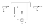
図1ないし図5は、この発明の実施の形態を示している。この実施の形態において、空調設備は、図5に示すように例えば、空気調和機101を通した空気(給気)を搬送する給気ダクトSAと、外気を取り込み外調器102で混合された空気(外気)SOAを搬送する外気ダクトOAとから搬送されるそれぞれの空気(給気と外気)をダンパ付空調用ボックス1で混合し、居室空間の天井などに設置された吹出口(アネモ)Vから吹き出すものである。図5の実施の形態では、還気と外気の混合を従来のように空気調和機101内ではなく、ダンパ付空調用ボックス1で行うようにしている。これにより、新鮮外気を給気受入の末端まで確実に搬送するとともに、外気流入量の個別調整を可能にしている。なお、外調機による温調は省略してもよい。
1 to 5 show an embodiment of the present invention. In this embodiment, as shown in FIG. 5, for example, the air-conditioning equipment is mixed with an air supply duct SA that conveys air (air supply) that has passed through the
ダンパ付空調用ボックス1は、図1に示すように、主として、箱状のボックス本体部2と、給気ダクトSAと接続される第1のダンパ3と、外気ダクトOAと接続される第2のダンパ4とを備えている。
As shown in FIG. 1, the damper-equipped
ボックス本体部2は、略1mmの板厚の鉄板で形成された1辺の長さが略300mmの立方体状で、図1に示すように、一の面としての底面2aに略円状に開口部21が形成されている。底面2aの開口部21には、後述するように吹出口Vが配設されるようになっている。そして、接続されるダクトは直径略100mmのフレキシブルダクトである。
The
ボックス本体部2の他の面としての一つの側面2bに、図1〜図3に示すように、切り起こしによって側面2bと一体に形成され、給気ダクトSAと開口部21とをそれぞれ連通する空気流量調整用の第1のダンパ3が配設されている。
As shown in FIGS. 1 to 3, one
第1のダンパ3は円弧状の軌跡を描く第1の切り込み部31と、第1の切り込み部31の基端部(半円状の円弧の立ち上がる起点部でありミシン目31b)を中心とした略線対称で、円弧状の軌跡を描く第2の切り込み部32とによって形成されている。すなわち、第1の切り込み部31と第2の切り込み部32とは同一円周上に位置している。第1の切り込み部31は、円弧状の切れ目31aと基端部側の直線状のミシン目31bとで構成されている。第2の切り込み部32は、第1の切り込み部31と同様に構成されている。この円弧状の切れ目31aと32aは、同一円周上にd2だけ間隔をおいて形成されている。また、ミシン目31bと32bとの間は、d1(<d2)だけ間隔をおいて形成されている。つまり、ミシン目31bと32bの切れ込み方向は、円弧状の切れ目31aと32aの端部よりも円弧の内側に形成されている。そして、この第1の切り込み部31と第2の切り込み部32とは、ミシン目31bと32bから切起こし可能(折曲可能)となっている。そして、図1に示すように、第1の切り込み部31と第2の切り込み部32とを互いに接近するようにボックス本体部2の内側または外側に折り曲げ立設させるべく第1のダンパ3が構成されている。ここで、第1の切り込み部31と第2の切り込み部32の折曲方向は、後日の保守を考慮するとボックス本体部2の内側が望ましいが、試運転時のみの調整であればボックス本体部2の外側に折り曲げてもよい。また、この第1の切り込み部31と第2の切り込み部32の折曲角度は調節自在で、折曲角度が大きいほど(第1の切り込み部31と第2の切り込み部32が立設するほど)開度は大きくなり、折曲角度が小さいほど開度は小さくなる。つまり、第1の切り込み部31と第2の切り込み部32を折り曲げるほど大きな風量の空気が供給される。
The
この第1のダンパ3の開口部(円弧状の切れ目31と32とで形成される円周上)には、給気ダクトSAとしてのフレキシブルダクトがカラー(図示略)を介して接続されるようになっている。なお、カラーはボックス本体部2にスポット溶接されている。
A flexible duct as an air supply duct SA is connected to an opening of the first damper 3 (on the circumference formed by the arc-shaped
ボックス本体部2の他の側面2cには、図1〜図3に示すように、第1のダンパ3と同様に、切り起こしによって他の側面2cと一体に形成され、外気ダクトOAと開口部21とをそれぞれ連通する空気流量調整用の第2のダンパ4が配設されている。
As shown in FIGS. 1 to 3, the
第2のダンパ4は円弧状の軌跡を描く第1の切り込み部41と、第1の切り込み部41の基端部(半円状の円弧の立ち上がる起点部でありミシン目31b)を中心とした略線対称で、円弧状の軌跡を描く第2の切り込み部42とによって形成されている。すなわち、第1の切り込み部41と第2の切り込み部42とは同一円周上に位置している。第1の切り込み部41は、円弧状の切れ目41aと基端部側の直線状のミシン目41bとで構成されている。第2の切り込み部42は、第1の切り込み部31と同様に構成されている。この円弧状の切れ目41aと42aは、同一円周上にd2だけ間隔をおいて形成されている。また、ミシン目41bと42bとの間は、d1(<d2)だけ間隔をおいて形成されている。つまり、ミシン目41bと42bの切れ込み方向は、円弧状の切れ目41aと42aの端部よりも円弧の内側に形成されている。そして、この第1の切り込み部41と第2の切り込み部42とは、ミシン目41bと42bから切起こし可能(折曲可能)となっている。そして、図1に示すように、第1の切り込み部41と第2の切り込み部42とを互いに接近するようにボックス本体部2の内側または外側に折り曲げ立設させるべく第2のダンパ4が構成されている。ここで、第1の切り込み部41と第2の切り込み部42の折曲方向は、後日の保守を考慮するとボックス本体部2の内側が望ましいが、試運転時のみの調整であればボックス本体部2の外側に折り曲げてもよい。また、この第1の切り込み部41と第2の切り込み部42の折曲角度は調節自在で、折曲角度が大きいほど(第1の切り込み部41と第2の切り込み部42が立設するほど)開度は大きくなり、折曲角度が小さいほど開度は小さくなる。つまり、第1の切り込み部41と第2の切り込み部42を折り曲げるほど大きな風量の空気が供給される。
The second damper 4 is centered on a
この第2のダンパ4の開口部(円弧状の切れ目41と42とで形成される円周上)には、外気ダクトOAとしてのフレキシブルダクトがカラーを介して接続されるようになっている。なお、カラーはボックス本体部2にスポット溶接されている。以上により、温調済の還気と新鮮外気を試運転時に好適な割合で混合できる。
A flexible duct as an outside air duct OA is connected to the opening of the second damper 4 (on the circumference formed by the arc-shaped
このような構成のダンパ付空調用ボックス1によって、給気ダクトSAから搬送される給気は、第1のダンパ3によって流量が調節され、外気ダクトOAから搬送される外気は、第2のダンパ4によって流量が調節される。そして、ダンパ付空調用ボックス1において、吹出口Vから吹き出される空気は所定の流量となっている。第1のダンパ3と第2のダンパ4から流入する空気は、ボックス本体部2の内部において衝突して、底面に形成された開口部21から押し出されるので、部品点数の少ない簡易な構造でも効率的に空気を混合することができる。
With the
次に、このような構成のダンパ付空調用ボックス1の取付け方法および作用について説明する。
Next, the mounting method and operation of the damper-equipped
まず、空調設備の施工に際して、給気ダクトSAや外気ダクトOAなどが天井近傍に配設される。次に、給気ダクトSAや外気ダクトOAなどの下方に、すなわち、天井面から所定距離だけ下方に天井下地R1、天井ボードR2が、吹出口Vの配設位置を除いて配設される。ここで、天井下地R1、天井ボードR2と天井面との間に形成された空間を天井裏といい、居室空間の天井面を第2の天井面という。 First, when constructing an air conditioning facility, an air supply duct SA, an outside air duct OA, and the like are disposed near the ceiling. Next, the ceiling base R1 and the ceiling board R2 are disposed below the air supply duct SA, the outside air duct OA, etc., that is, below the ceiling surface by a predetermined distance except for the position where the air outlet V is disposed. Here, the space formed between the ceiling base R1 and the ceiling board R2 and the ceiling surface is referred to as the ceiling back, and the ceiling surface of the living room space is referred to as the second ceiling surface.
また、ダンパ付空調用ボックス1の第1のダンパ3、第2のダンパ4をダンパ付空調用ボックス1の内側に切起こして立設させ、ダンパ付空調用ボックス1の第1のダンパ3の開口部に給気ダクトSAとの接続用のカラーを、第2のダンパ4の開口部に外気ダクトOAとの接続用のカラーを、それぞれスポット溶接などで配設しておく。
In addition, the
そして、天井下地R1、天井ボードR2に開口部(吹出口Vの配設位置)21を構成する前に、ダンパ付空調用ボックス1を、天井スラブに設けた吊ボルト(図示略)によって吊っておく。また、第1のダンパ3側のカラーに給気ダクトSAを接続し、第2のダンパ4側のカラーに外気ダクトOAをバンド等で接続する。さらに、ダンパ付空調用ボックス1やカラーなどの外周には断熱材が貼り付けられる。
And before constructing the opening part 21 (disposition position of the blower outlet V) 21 in the ceiling base R1 and the ceiling board R2, the
そして、開口部21を形成した後、居室空間側から図4に示すようにダンパ付空調用ボックス1の底面2aの開口部21に接続用のダクト(短管)を介して吹出口Vが配設される。
After the
つぎに、空気調和機101を試運転して吹出口Vから吹き出される空気の流量などを測定し、所定値(設計値)となっているか否かが確認される。所定値となっていない場合は、吹出口Vのフェース部、例えばアネモであれば中コーン(図示略)が取外されて、吹出口V側からダンパ付空調用ボックス1の内部へ手が挿入されて、第1のダンパ3、第2のダンパ4の折曲角度が調節されることによって開度が調整される。
Next, the
このようにして、図4に示すように、第2の天井面には所定の位置に吹出口Vが設置されて、空調設備の施工が完了する。そして、給気ダクトSAから搬送された給気は第1のダンパ3によって、所定の流量に調節されてダンパ付空調用ボックス1に搬送され、外気ダクトOAから搬送された外気SOAは第2のダンパ4によって、所定の流量に調節されてダンパ付空調用ボックス1に搬送される。そして、ダンパ付空調用ボックス1において、給気と外気SOAとが混合されて吹出口Vから居室空間へ吹き出されるようになっている。
In this manner, as shown in FIG. 4, the outlet V is installed at a predetermined position on the second ceiling surface, and the construction of the air conditioning equipment is completed. Then, the air supplied from the air supply duct SA is adjusted to a predetermined flow rate by the
以上のように、この実施の形態に係る発明によれば、空気流量調整用の第1のダンパ3、第2のダンパ4は、ボックス本体部2の側面2b、2cに切り起こしによって側面2b、2cと一体に形成されているので、従来技術のようにボックス本体部2以外の部位に新たにダンパを設ける必要がなく、ダンパの取付け労力を大幅に低減可能である。また、第1のダンパ3、第2のダンパ4はボックス本体部2の側面と一体に形成されているので、ダンパを構成する部品点数を少なくでき構造を簡素化するとともに、設置場所を省スペース化することができる。さらに、第1のダンパ3、第2のダンパ4の切り起こし角度を変えることで、第1のダンパ3、第2のダンパ4の形状、つまり、空気の流路の開度をかえることができるので、第1のダンパ3、第2のダンパ4を通過する空気を所定の流量に調節自在である。
As described above, according to the invention according to the present embodiment, the
また、流量を調節するため第1のダンパ3、第2のダンパ4は第1の切り込み部31、41と第2の切り込み部32、42とを互いに接近するようにボックス本体部2の内側に折り曲げ立設させることで構成されているので、第1の切り込み部31、41と第2の切り込み部32、42との折り曲げ角度を調整することにより、空気流量調整を容易に行うことができる。また、第1のダンパ3、第2のダンパ4はミシン目によって第1の切り込み部31、41と第2の切込部32、42とを容易に折り曲げることができる。
Further, in order to adjust the flow rate, the
また、第1のダンパ3と第2のダンパ4とから流入する空気は、ボックス本体部2の内部において衝突して、底面に形成された開口部21から押し出されるので、部品点数の少ない簡易な構造でも効率的に空気を混合することができる。
Further, the air flowing in from the
さらに、ダンパ付空調用ボックス1の設置は、天井裏に給気ダクトSAや外気ダクトOAなどを配設した後に、吹出口Vの配設位置に設けられた開口部21から、つまり、居室空間側から行うことができるので、施工が容易である。
Furthermore, the
以上、この発明の実施の形態について説明したが、具体的な構成は、上記の実施の形態に限られるものではなく、この発明の要旨を逸脱しない範囲の設計の変更等があっても、この発明に含まれる。例えば、この実施の形態ではダンパ付空調用ボックス1の側面をダクト接続の開口として、ここにはダンパを設けず、底面の吹出口接続部のダクトに本発明のダンパを設けてもよい。また、ダンパ付空調用ボックス1には第1のダンパ3、第2のダンパ4を備えるようにして説明したが、いずれか一方のみにダンパを配設するようにしてもよい。また、上記の実施の形態では、第1の切り込み部31、41、第2の切り込み部32、42はいずれも円弧状の軌跡を描くようにしたが、切り込み部が描く軌跡は三角形状や四角形状などの多角形状であっても、円弧以外の曲線状であってもよい。
Although the embodiment of the present invention has been described above, the specific configuration is not limited to the above embodiment, and even if there is a design change or the like without departing from the gist of the present invention, Included in the invention. For example, in this embodiment, the side surface of the damper-equipped
さらに、この実施の形態ではダンパ付空調用ボックス1を空気調和機からの給気に使用する場合について説明したが、空気調和機への還気に使用できること、すなわち吹込口ボックスとして使用することはもちろんである。
Furthermore, although this embodiment demonstrated the case where the
1 ダンパ付空調用ボックス
2 ボックス本体部
2a 底面(一の面)
2b 一つの側面(他の面)
2c 他の側面
3 第1のダンパ
31 第1の切り込み部
32 第2の切り込み部
4 第2のダンパ
41 第1の切り込み部
42 第2の切り込み部
V 吹出口
R1 天井下地
R2 天井ボード
SA 給気ダクト
OA 外気ダクト
1 Air-conditioning box with
2b One side (other side)
2c
Claims (4)
前記ボックス本体部の一つの面に形成される開口部と、
前記ボックス本体部の他の面に切り起こしによって前記他の面と一体に形成され、前記ダクトと前記開口部とを連通する空気流量調整用のダンパと、
を備えたことを特徴とするダンパ付空調用ボックス。 A box-shaped box body to which a duct can be connected;
An opening formed in one surface of the box body,
A damper for adjusting the air flow rate formed integrally with the other surface by cutting and raising the other surface of the box body, and communicating the duct and the opening;
A box for air conditioning with a damper, characterized by comprising
前記ダンパは、前記ボックス本体部の複数の側面に形成され、前記開口部は前記ボックスの底面に形成されている、ことを特徴とする請求項1から3のいずれか1項に記載のダンパ付空調用ボックス。 The box body has a substantially horizontal top and bottom surface,
The damper according to any one of claims 1 to 3, wherein the damper is formed on a plurality of side surfaces of the box body, and the opening is formed on a bottom surface of the box. Air conditioning box.
Priority Applications (1)
| Application Number | Priority Date | Filing Date | Title |
|---|---|---|---|
| JP2011003563A JP2012145265A (en) | 2011-01-12 | 2011-01-12 | Box for air conditioning with damper |
Applications Claiming Priority (1)
| Application Number | Priority Date | Filing Date | Title |
|---|---|---|---|
| JP2011003563A JP2012145265A (en) | 2011-01-12 | 2011-01-12 | Box for air conditioning with damper |
Publications (1)
| Publication Number | Publication Date |
|---|---|
| JP2012145265A true JP2012145265A (en) | 2012-08-02 |
Family
ID=46789001
Family Applications (1)
| Application Number | Title | Priority Date | Filing Date |
|---|---|---|---|
| JP2011003563A Pending JP2012145265A (en) | 2011-01-12 | 2011-01-12 | Box for air conditioning with damper |
Country Status (1)
| Country | Link |
|---|---|
| JP (1) | JP2012145265A (en) |
Cited By (1)
| Publication number | Priority date | Publication date | Assignee | Title |
|---|---|---|---|---|
| CN113154544A (en) * | 2021-04-25 | 2021-07-23 | 珠海格力电器股份有限公司 | Protection device of air outlet equipment, air conditioner and protection control method of air conditioner |
Citations (4)
| Publication number | Priority date | Publication date | Assignee | Title |
|---|---|---|---|---|
| JPH08270974A (en) * | 1995-03-30 | 1996-10-18 | Mitsubishi Electric Corp | Air conditioner |
| JPH09196454A (en) * | 1996-01-24 | 1997-07-31 | Matsushita Seiko Co Ltd | Quantity-of-air adjuster |
| JP3043110U (en) * | 1997-04-21 | 1997-11-11 | 富士空調工業株式会社 | Air conditioning damper device |
| JP2001280678A (en) * | 2000-03-31 | 2001-10-10 | Kimura Kohki Co Ltd | Blowout unit |
-
2011
- 2011-01-12 JP JP2011003563A patent/JP2012145265A/en active Pending
Patent Citations (4)
| Publication number | Priority date | Publication date | Assignee | Title |
|---|---|---|---|---|
| JPH08270974A (en) * | 1995-03-30 | 1996-10-18 | Mitsubishi Electric Corp | Air conditioner |
| JPH09196454A (en) * | 1996-01-24 | 1997-07-31 | Matsushita Seiko Co Ltd | Quantity-of-air adjuster |
| JP3043110U (en) * | 1997-04-21 | 1997-11-11 | 富士空調工業株式会社 | Air conditioning damper device |
| JP2001280678A (en) * | 2000-03-31 | 2001-10-10 | Kimura Kohki Co Ltd | Blowout unit |
Cited By (1)
| Publication number | Priority date | Publication date | Assignee | Title |
|---|---|---|---|---|
| CN113154544A (en) * | 2021-04-25 | 2021-07-23 | 珠海格力电器股份有限公司 | Protection device of air outlet equipment, air conditioner and protection control method of air conditioner |
Similar Documents
| Publication | Publication Date | Title |
|---|---|---|
| JP5667270B1 (en) | Grill-type induction outlet | |
| WO2017166935A1 (en) | Indoor air conditioning unit | |
| JPWO2009020173A1 (en) | Blower and air conditioner | |
| CN105546648B (en) | Air conditioner indoor unit and air-conditioning system | |
| CN107166514A (en) | Indoor apparatus of air conditioner | |
| JP2016164463A (en) | Air conditioner indoor unit | |
| JP7217596B2 (en) | air conditioning system | |
| CN106052063A (en) | Air deflector and air conditioner | |
| JP6184190B2 (en) | Low temperature blowout device | |
| JP2012145265A (en) | Box for air conditioning with damper | |
| EP3130860B1 (en) | Air conditioner | |
| JP5502665B2 (en) | Air outlet device | |
| CN209181084U (en) | Air conditioner | |
| JP2017142029A (en) | Air conditioning outlet and air conditioning system using the same | |
| CN107490067B (en) | Indoor unit and air conditioning system | |
| JP5966149B2 (en) | Air conditioner | |
| JP2002039606A (en) | Air supply fan unit | |
| CN107687671B (en) | Indoor units and air conditioning systems | |
| CN207379017U (en) | Air supply device and air conditioning system using same | |
| JP2006183930A (en) | Chamber for air-conditioning equipment | |
| JP6700582B2 (en) | Air conditioning system | |
| JP2014126347A (en) | Air supply chamber | |
| JP6153141B2 (en) | Air conditioner | |
| JP6465769B2 (en) | Branch chamber | |
| JP2008209039A (en) | Air supply equalizing device and air supply outlet device |
Legal Events
| Date | Code | Title | Description |
|---|---|---|---|
| A621 | Written request for application examination |
Free format text: JAPANESE INTERMEDIATE CODE: A621 Effective date: 20131031 |
|
| A977 | Report on retrieval |
Free format text: JAPANESE INTERMEDIATE CODE: A971007 Effective date: 20140515 |
|
| A131 | Notification of reasons for refusal |
Free format text: JAPANESE INTERMEDIATE CODE: A131 Effective date: 20140520 |
|
| A521 | Written amendment |
Free format text: JAPANESE INTERMEDIATE CODE: A523 Effective date: 20140710 |
|
| A02 | Decision of refusal |
Free format text: JAPANESE INTERMEDIATE CODE: A02 Effective date: 20150203 |