JP2012145341A - Method for determining packing leak from exhaust gas sensor installation section and program for the same - Google Patents
Method for determining packing leak from exhaust gas sensor installation section and program for the same Download PDFInfo
- Publication number
- JP2012145341A JP2012145341A JP2011001568A JP2011001568A JP2012145341A JP 2012145341 A JP2012145341 A JP 2012145341A JP 2011001568 A JP2011001568 A JP 2011001568A JP 2011001568 A JP2011001568 A JP 2011001568A JP 2012145341 A JP2012145341 A JP 2012145341A
- Authority
- JP
- Japan
- Prior art keywords
- exhaust gas
- gas sensor
- packing
- output
- sensor
- Prior art date
- Legal status (The legal status is an assumption and is not a legal conclusion. Google has not performed a legal analysis and makes no representation as to the accuracy of the status listed.)
- Pending
Links
Images


Landscapes
- Investigating Or Analyzing Materials By The Use Of Electric Means (AREA)
Abstract
Description
本発明は、主として、燃焼機器からの排ガス中に含まれる一酸化炭素などの濃度を検出する排ガスセンサがパッキンを介して取り付けられている場合に、そのパッキン部から外部への排ガスの漏れを判定するための方法とプログラムに関するものである。 In the present invention, when an exhaust gas sensor that detects the concentration of carbon monoxide or the like contained in exhaust gas from a combustion device is attached via a packing, leakage of the exhaust gas from the packing portion to the outside is mainly determined. It relates to a method and a program.
下記特許文献1に開示されるように、ボイラまたは給湯器などの燃焼機器には、排ガス中の一酸化炭素の濃度を検出するCOセンサなど、各種の排ガスセンサが設けられる。この種の排ガスセンサの中には、排ガスセンサ付近の排ガスの流速の変化により出力に影響を受けるものもある。
As disclosed in the following
従って、パッキンを用いて排ガスセンサが設けられている状況で、パッキンの劣化などにより、パッキン部から排ガスが漏れる場合には、これを検知しなければ、正確な測定ができないことになる。つまり、パッキン部から排ガスが漏れる場合、パッキンが正常に機能している場合と比較して、排ガスの流れが変わるので、排ガスセンサにおける流速の違いにより、排ガスセンサの出力に誤差を生じるおそれがある。 Therefore, in the situation where the exhaust gas sensor is provided using the packing, when exhaust gas leaks from the packing part due to deterioration of the packing or the like, accurate measurement cannot be performed unless this is detected. In other words, when the exhaust gas leaks from the packing part, the flow of the exhaust gas changes as compared with the case where the packing functions normally, and therefore there is a risk of causing an error in the output of the exhaust gas sensor due to the difference in the flow velocity of the exhaust gas sensor. .
本発明が解決しようとする課題は、燃焼機器からの排ガス中に含まれる一酸化炭素などの濃度を検出する排ガスセンサの設置部にパッキンを有する場合に、そのパッキン部から外部への排ガスの漏れを判定することにある。 The problem to be solved by the present invention is that when there is a packing in the installation part of the exhaust gas sensor for detecting the concentration of carbon monoxide or the like contained in the exhaust gas from the combustion equipment, the leakage of the exhaust gas from the packing part to the outside It is in judging.
本発明は、前記課題を解決するためになされたもので、請求項1に記載の発明は、排ガス中の一酸化炭素、二酸化炭素、酸素または窒素酸化物の濃度を検出する排ガスセンサの設置部にパッキンを有する排ガス測定装置を備え、この排ガス測定装置が燃焼機器からの排ガス路に設けられたシステムに適用され、前記パッキンの箇所から外部への排ガスの漏れを判定する方法であって、前記排ガスセンサは、排ガスの流速の変化により出力に影響を受けるセンサであり、前記燃焼機器の停止中における前記排ガスセンサの出力と、前記燃焼機器のプレパージ中における前記排ガスセンサの出力とに基づき、前記パッキンの箇所から外部への排ガスの漏れを判定することを特徴とする排ガスセンサ設置部のパッキン漏れ判定方法である。
The present invention has been made in order to solve the above-mentioned problems, and the invention according to
請求項1に記載の発明によれば、燃焼機器の停止中における排ガスセンサの出力と、燃焼機器のプレパージ中における排ガスセンサの出力とに基づき、パッキン部から外部への排ガスの漏れを判定することができる。つまり、停止中もプレパージ中も、燃料の燃焼はなされていない状態であるから、排ガスセンサは外気と同様の環境にさらされ、排ガスセンサの出力は同等のはずであるところ、出力に設定以上の差が生じれば、パッキン部からの漏れによる流速変化の影響と判定することができる。 According to the first aspect of the present invention, the leakage of the exhaust gas from the packing part to the outside is determined based on the output of the exhaust gas sensor while the combustion device is stopped and the output of the exhaust gas sensor during the pre-purge of the combustion device. Can do. In other words, the fuel is not combusted during both stoppage and pre-purge, so the exhaust gas sensor is exposed to the same environment as the outside air, and the output of the exhaust gas sensor should be the same, but the output exceeds the set value. If a difference arises, it can be determined that the influence of the flow velocity change due to leakage from the packing portion.
請求項2に記載の発明は、前記プレパージ中の前記排ガスセンサの出力として、前記プレパージの終盤における出力を用いることを特徴とする請求項1に記載の排ガスセンサ設置部のパッキン漏れ判定方法である。
The invention according to
請求項2に記載の発明によれば、燃焼機器内に溜まっていたガスを外部へ放出するプレパージの終盤における出力を、プレパージ中の排ガスセンサの出力として採用することで、燃焼機器内に溜まっていたガスの影響を防止して、パッキン部からの漏れ判定を正確に行うことができる。 According to the second aspect of the present invention, the output at the end of the pre-purge for releasing the gas accumulated in the combustion equipment to the outside is adopted as the output of the exhaust gas sensor during the pre-purge, so that the gas is accumulated in the combustion equipment. This makes it possible to accurately determine the leakage from the packing portion by preventing the influence of the gas.
請求項3に記載の発明は、前記燃焼機器は、ボイラまたは給湯器であり、前記排ガスセンサは、接触燃焼式のCOセンサであることを特徴とする請求項1または請求項2に記載の排ガスセンサ設置部のパッキン漏れ判定方法である。
The invention according to
請求項3に記載の発明によれば、ボイラまたは給湯器における接触燃焼式のCOセンサについても、そのセンサ設置部のパッキンからの排ガスの漏れを監視しつつ、正確に一酸化炭素濃度を測定することができる。 According to the third aspect of the present invention, the carbon monoxide concentration is accurately measured for the catalytic combustion type CO sensor in the boiler or water heater while monitoring the leakage of the exhaust gas from the packing of the sensor installation portion. be able to.
さらに、請求項4に記載の発明は、排ガス中の一酸化炭素、二酸化炭素、酸素または窒素酸化物の濃度を検出する排ガスセンサの設置部にパッキンを有する排ガス測定装置を備え、この排ガス測定装置が燃焼機器からの排ガス路に設けられたシステムに適用され、前記パッキンの箇所から外部への排ガスの漏れを判定するプログラムであって、前記排ガスセンサは、排ガスの流速の変化により出力に影響を受けるセンサであり、前記燃焼機器のプレパージ直前における前記排ガスセンサの出力を検出するステップと、前記燃焼機器のプレパージ中における前記排ガスセンサの出力を検出するステップと、前記各ステップで検出した前記排ガスセンサの出力の差に基づき、前記パッキンの箇所から外部への排ガスの漏れを判定するステップとをコンピュータに実行させるためのプログラムである。
Furthermore, the invention described in
請求項4に記載の発明によれば、燃焼機器の停止中における排ガスセンサの出力と、燃焼機器のプレパージ中における排ガスセンサの出力とに基づき、パッキン部から外部への排ガスの漏れを判定することができる。つまり、停止中もプレパージ中も、燃料の燃焼はなされていない状態であるから、排ガスセンサは外気と同様の環境にさらされ、排ガスセンサの出力は同等のはずであるところ、出力に設定以上の差が生じれば、パッキン部からの漏れによる流速変化の影響と判定することができる。
According to the invention described in
本発明によれば、燃焼機器からの排ガス中に含まれる一酸化炭素などの濃度を検出する排ガスセンサの設置部にパッキンを有する場合に、そのパッキン部から外部への排ガスの漏れを判定することができる。 According to the present invention, when there is a packing in the installation part of the exhaust gas sensor that detects the concentration of carbon monoxide or the like contained in the exhaust gas from the combustion device, the leakage of the exhaust gas from the packing part to the outside is determined. Can do.
以下、本発明の具体的実施例を図面に基づいて詳細に説明する。
図1は、本発明のパッキン漏れ判定方法が適用されるシステムの一実施例を示す概略図である。
Hereinafter, specific embodiments of the present invention will be described in detail with reference to the drawings.
FIG. 1 is a schematic diagram showing an embodiment of a system to which the packing leakage determination method of the present invention is applied.
本実施例のパッキン漏れ判定方法は、燃焼機器1からの排ガス路(排気筒2)に排ガス測定装置3が設けられたシステムに適用される。燃焼機器1は、油やガスなどの燃料を燃焼させる機器であり、その種類を特に問わないが、典型的にはボイラ4または給湯器である。
The packing leakage determination method of the present embodiment is applied to a system in which an exhaust
図示例では、燃焼機器1はボイラ4とされ、このボイラ4は、缶体5、バーナ6および送風機7などを備える。バーナ6は、油またはガスなどの燃料と、送風機7からの燃焼用空気とが供給され、缶体5内で燃料の燃焼を図る。これにより、缶体5内の水は、加熱され蒸気化される。そして、その蒸気は、各種の蒸気使用設備へ送られる。缶体5内で燃焼後の排ガスは、排気筒2を介して外部へ排出される。なお、燃焼機器1が給湯器の場合、蒸気に代えて温水を得ようする点は異なるが、同様の構成といえる。
In the illustrated example, the
排ガス路は、典型的には排気筒2、つまり煙道または煙突から構成される。そして、排ガス中の一酸化炭素、二酸化炭素、酸素または窒素酸化物の濃度を検出するために、排気筒2には、排ガス測定装置3が取り付けられる。
The exhaust gas path is typically composed of an
排ガス測定装置3は、排ガス中の一酸化炭素、二酸化炭素、酸素または窒素酸化物の濃度を検出する排ガスセンサ8を備える。本発明のパッキン漏れ判定方法が有効に機能するのは、排ガスセンサ8が、たとえば接触燃焼式のCOセンサのように、排ガスセンサ8への排ガスの流速の変化により出力に影響を受けてしまうセンサである。
The exhaust
排ガスセンサ8は、排気筒2の周側壁やこれに設けられる測定口などに直接に設けてもよいが、本実施例では、排気筒2の周側壁に抽出パイプ9を介して設けられる。いずれにしても、排ガスセンサ8の設置部から外部へ排ガスが漏れ出ないように、排ガスセンサ8はパッキン10を介して取り付けられる。
The
図示例の抽出パイプ9は、排気筒2の周側壁から離隔するに従って上方へ傾斜するよう設けられる。抽出パイプ9は、排気筒2を通る排ガスの一部を、取出し路11を介して取り出し、この取出し路11の端部で折り返して、戻し路12を介して排気筒2へ戻す構成とされる。そして、戻し路12に設けられた上方への凹部13(図2)内に、排ガスセンサ8が下向きに設けられる。
The extraction pipe 9 in the illustrated example is provided so as to be inclined upward as it is separated from the peripheral side wall of the
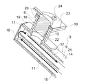
図2は、排ガス測定装置3の基端部を拡大して示す斜視断面図である。図1および図2に示すように、本実施例の抽出パイプ9は、断面矩形の外パイプ14と、この外パイプ14の断面下半分にはめ込まれる断面矩形の内パイプ15とから構成される。外パイプ14は、基端部が端壁16で閉塞される一方、先端部は開口されている。一方、内パイプ15は、基端部が前記端壁16と離隔して配置されることで、内パイプ15の基端部と外パイプ14の端壁16との間に、折返し開口17が形成される。また、内パイプ15は、外パイプ14の先端部よりも十分延出して設けられると共に、先端部が開口されている。
FIG. 2 is an enlarged perspective sectional view of the base end portion of the exhaust
このような構成であるから、外パイプ14および内パイプ15の各先端部を排気筒2内に開口させれば、内パイプ15内が前記取出し路11、外パイプ14内で且つ内パイプ15外が前記戻し路12として機能する。つまり、排気筒2の排ガスは、内パイプ15の先端部から導入され、内パイプ15の先端部から基端部へ移動し、折返し開口17から内パイプ15外で外パイプ14内に導出され、外パイプ14の基端部から先端部へ移動し、外パイプ14の先端部から排気筒2内へ戻される。なお、図1では、外パイプ14の先端部は、排気筒2の周側壁において開口され、内パイプ15の先端部は、排気筒2内に突入された状態で開口されている。
With such a configuration, if the tip ends of the
抽出パイプ9には、センサ取付筒18を介して排ガスセンサ8が設けられる。センサ取付筒18は、円筒状または角筒状であり、軸方向両端部にフランジ(下方フランジ19、上方フランジ20)を備える。そして、センサ取付筒18は、下方フランジ19が、外パイプ14の上壁21に気密状態に固定される。なお、外パイプ14の上壁21には、センサ取付筒18の中空穴と対応した位置に、予め穴が開けられている。このようにして、排ガスの戻し路12には、上方への凹部13が設けられる。
An
センサ取付筒18の中空穴で構成される凹部13には、排ガスセンサ8が設けられる。本実施例では、排ガスセンサ8は、円柱状の本体部22の上端部に、フランジ23が設けられてなる。従って、排ガスセンサ8は、本体部22が、センサ取付筒18の中空穴に上方から差し込まれ、フランジ23が、センサ取付筒18の上方フランジ20にパッキン10を介して重ね合わせてネジ24で固定される。両フランジ20,23間にパッキン10を挟み込むことで、両フランジ20,23間の隙間を封止し、センサ取付筒18を介して外部へ排ガスが逃げることが防止される。
The
排ガスセンサ8は、制御器(図示省略)に接続され、制御器では、所定のプログラムに従い、排ガスセンサ8の出力に基づき、排ガスセンサ8の設置部のパッキン10の箇所から外部への排ガスの漏れを検知する。以下、このパッキン漏れ判定方法について説明する。
The
図3は、排ガスセンサ(たとえば接触燃焼式COセンサ)8の出力と経過時間との関係の一例を示す概略図である。この図に示すように、通常、燃焼機器1は、停止状態(待機中)S1からプレパージ工程S2を介して燃焼工程S3へ移行する。
FIG. 3 is a schematic diagram illustrating an example of the relationship between the output of the exhaust gas sensor (for example, the catalytic combustion CO sensor) 8 and the elapsed time. As shown in this figure, normally, the
燃焼機器の停止S1中、バーナ6および送風機7は停止している。一方、プレパージ工程S2では、バーナ6を停止した状態で、送風機7を作動させる。つまり、バーナ6による燃料の燃焼は停止した状態で、送風機7から缶体5内へ空気を送り込んで排気筒2から放出することで、缶体5内および排気筒2内の換気が図られる。その後、バーナ6を作動させて、バーナ6からの燃料に着火し、バーナ6からの燃料を燃焼させる燃焼工程S3へ移行する。燃焼工程S3では、適宜、燃焼量を調整してもよい。
During the stop S1 of the combustion equipment, the
燃焼機器1の停止S1中もプレパージ工程S2中も、燃料の燃焼はなされていない状態である。従って、排ガスセンサ8は、外気と同様の環境にさらされ、排ガスセンサ8の出力は同等のはずである。理想的には、図3において線Aで示すように、プレパージ工程S2中の排ガスセンサ8の出力は、停止S1中の排ガスセンサ8の出力と変わらない。
The fuel is not burned during the stop S1 of the
ところが、もし、パッキン10の劣化などにより、パッキン10の箇所から排ガスが外部へ漏れ出るとする。この場合、排ガスは、排ガスセンサ8を介して外部へ漏れ出るので、排ガスセンサ8の出力は、流速の影響を受けた出力となる。たとえば、図3において線Bまたは線Cで示すように、前述した理想状態(線A)とはずれた出力となる。
However, it is assumed that exhaust gas leaks from the location of the packing 10 due to deterioration of the packing 10 or the like. In this case, since the exhaust gas leaks outside through the
そこで、燃焼機器1の停止S1中における排ガスセンサ8の出力と、燃焼機器1のプレパージ工程S2中における排ガスセンサ8の出力とに基づき、パッキン10の箇所から外部への排ガスの漏れを判定することができる。具体的には、制御器は、停止S1中の排ガスセンサ8の出力と、プレパージ工程S2中の排ガスセンサ8の出力とを得て、両者に設定以上の差が生じれば、パッキン部10からの漏れがあると判定する。そして、漏れがあると判定した場合には、その旨の警報を発し、メンテナンスを要求すればよい。
Therefore, the leakage of the exhaust gas from the location of the packing 10 to the outside is determined based on the output of the
ところで、プレパージ工程S2の初期には、缶体5内に残っていたガスの影響を受ける可能性があるので、プレパージ工程S2の終盤(たとえば図3における時間T2)における出力と、停止中(たとえばプレパージ直前の時間T1)の出力とを比較するのが好ましい。
By the way, in the initial stage of the pre-purge process S2, there is a possibility of being affected by the gas remaining in the
前述したように、制御器は、パッキン10の箇所から外部への排ガスの漏れを判定するプログラムを備え、このプログラムで上述のとおり、パッキン漏れの判定が可能とされる。つまり、燃焼機器1の停止中(たとえばプレパージ直前の時間T1)における排ガスセンサ8の出力を検出するステップと、燃焼機器1のプレパージ工程S2中(たとえばプレパージ終盤の時間T2)における排ガスセンサ8の出力を検出するステップと、前記各ステップで検出した排ガスセンサ8の出力の差に基づき、パッキン10の箇所から外部への排ガスの漏れを判定するステップとを含んでいる。
As described above, the controller includes a program for determining leakage of exhaust gas from the location of the packing 10 to the outside, and this program enables determination of packing leakage as described above. That is, the step of detecting the output of the
本実施例のパッキン漏れ判定方法およびそのプログラムによれば、排ガスセンサ8の設置部におけるパッキン10から外部への排ガスの漏れを、簡易に判定することができる。しかも、排ガスセンサ8の出力は、排ガスセンサ8への気体の流速だけでなく温度などにも影響するが、燃焼機器1のプレパージ工程S2中とその直前の出力とを比較することで、温度などの影響も受けない構成となる。
According to the packing leakage determination method and its program of the present embodiment, it is possible to easily determine the leakage of exhaust gas from the packing 10 to the outside in the installation portion of the
本発明の排ガスセンサ設置部のパッキン漏れ判定方法およびそのプログラムは、上記実施例の構成に限らず適宜変更可能である。特に、燃焼機器1からの排ガス路に排ガスセンサ8を設ける構成、たとえば抽出パイプ9やそれへの排ガスセンサ8の取付構造については適宜に変更可能である。要は、排ガスの流速の変化により出力に影響を受ける排ガスセンサ8の設置部にパッキン10を備えるシステムであれば、燃焼機器1や排ガス測定装置3の構成は適宜に変更可能である。
The packing leak determination method and program for the exhaust gas sensor installation section of the present invention are not limited to the configuration of the above-described embodiment, and can be changed as appropriate. In particular, the configuration in which the
1 燃焼機器
2 排気筒(排ガス路)
3 排ガス測定装置
4 ボイラ
8 排ガスセンサ
9 抽出パイプ
10 パッキン
S1 燃焼機器の停止中
S2 プレパージ工程
S3 燃焼工程
1
DESCRIPTION OF
Claims (4)
前記排ガスセンサは、排ガスの流速の変化により出力に影響を受けるセンサであり、
前記燃焼機器の停止中における前記排ガスセンサの出力と、前記燃焼機器のプレパージ中における前記排ガスセンサの出力とに基づき、前記パッキンの箇所から外部への排ガスの漏れを判定する
ことを特徴とする排ガスセンサ設置部のパッキン漏れ判定方法。 An exhaust gas measuring device having a packing is provided at the installation part of the exhaust gas sensor for detecting the concentration of carbon monoxide, carbon dioxide, oxygen or nitrogen oxide in the exhaust gas, and this exhaust gas measuring device is provided in the exhaust gas path from the combustion equipment. A method for determining leakage of exhaust gas from a location of the packing to the outside applied to a system,
The exhaust gas sensor is a sensor that is affected by output due to a change in the flow rate of exhaust gas,
Exhaust gas leaking from the location of the packing to the outside is determined based on the output of the exhaust gas sensor when the combustion device is stopped and the output of the exhaust gas sensor during pre-purge of the combustion device. Packing leak judgment method for the sensor installation part.
ことを特徴とする請求項1に記載の排ガスセンサ設置部のパッキン漏れ判定方法。 The packing leak determination method for an exhaust gas sensor installation unit according to claim 1, wherein the output at the end of the pre-purge is used as the output of the exhaust gas sensor during the pre-purge.
前記排ガスセンサは、接触燃焼式のCOセンサである
ことを特徴とする請求項1または請求項2に記載の排ガスセンサ設置部のパッキン漏れ判定方法。 The combustion device is a boiler or a water heater,
The said exhaust gas sensor is a contact combustion-type CO sensor. The packing leak determination method of the exhaust gas sensor installation part of Claim 1 or Claim 2 characterized by the above-mentioned.
前記排ガスセンサは、排ガスの流速の変化により出力に影響を受けるセンサであり、
前記燃焼機器のプレパージ直前における前記排ガスセンサの出力を検出するステップと、
前記燃焼機器のプレパージ中における前記排ガスセンサの出力を検出するステップと、
前記各ステップで検出した前記排ガスセンサの出力の差に基づき、前記パッキンの箇所から外部への排ガスの漏れを判定するステップと
をコンピュータに実行させるためのプログラム。 An exhaust gas measuring device having a packing is provided at the installation part of the exhaust gas sensor for detecting the concentration of carbon monoxide, carbon dioxide, oxygen or nitrogen oxide in the exhaust gas, and this exhaust gas measuring device is provided in the exhaust gas path from the combustion equipment. A program that is applied to a system and determines leakage of exhaust gas from a location of the packing to the outside,
The exhaust gas sensor is a sensor that is affected by output due to a change in the flow rate of exhaust gas,
Detecting the output of the exhaust gas sensor immediately before the pre-purge of the combustion device;
Detecting the output of the exhaust gas sensor during pre-purge of the combustion device;
A program for causing a computer to execute a step of determining leakage of exhaust gas from the location of the packing to the outside based on a difference in output of the exhaust gas sensor detected in each step.
Priority Applications (1)
| Application Number | Priority Date | Filing Date | Title |
|---|---|---|---|
| JP2011001568A JP2012145341A (en) | 2011-01-07 | 2011-01-07 | Method for determining packing leak from exhaust gas sensor installation section and program for the same |
Applications Claiming Priority (1)
| Application Number | Priority Date | Filing Date | Title |
|---|---|---|---|
| JP2011001568A JP2012145341A (en) | 2011-01-07 | 2011-01-07 | Method for determining packing leak from exhaust gas sensor installation section and program for the same |
Publications (1)
| Publication Number | Publication Date |
|---|---|
| JP2012145341A true JP2012145341A (en) | 2012-08-02 |
Family
ID=46789059
Family Applications (1)
| Application Number | Title | Priority Date | Filing Date |
|---|---|---|---|
| JP2011001568A Pending JP2012145341A (en) | 2011-01-07 | 2011-01-07 | Method for determining packing leak from exhaust gas sensor installation section and program for the same |
Country Status (1)
| Country | Link |
|---|---|
| JP (1) | JP2012145341A (en) |
Cited By (3)
| Publication number | Priority date | Publication date | Assignee | Title |
|---|---|---|---|---|
| JP2012145523A (en) * | 2011-01-14 | 2012-08-02 | Miura Co Ltd | Exhaust gas measuring device |
| CN105181257A (en) * | 2015-08-14 | 2015-12-23 | 中国神华能源股份有限公司 | Oxygen-rich combustion air leak monitoring method and system |
| JP2016114312A (en) * | 2014-12-16 | 2016-06-23 | 三浦工業株式会社 | Gas burning boiler |
-
2011
- 2011-01-07 JP JP2011001568A patent/JP2012145341A/en active Pending
Cited By (3)
| Publication number | Priority date | Publication date | Assignee | Title |
|---|---|---|---|---|
| JP2012145523A (en) * | 2011-01-14 | 2012-08-02 | Miura Co Ltd | Exhaust gas measuring device |
| JP2016114312A (en) * | 2014-12-16 | 2016-06-23 | 三浦工業株式会社 | Gas burning boiler |
| CN105181257A (en) * | 2015-08-14 | 2015-12-23 | 中国神华能源股份有限公司 | Oxygen-rich combustion air leak monitoring method and system |
Similar Documents
| Publication | Publication Date | Title |
|---|---|---|
| JP5545451B2 (en) | Exhaust gas measuring device | |
| MX2009008076A (en) | Method of detecting a partial flame failure in a gas turbine engine and a gas turbine engine. | |
| JP2010159739A (en) | System and method for detecting flame in fuel nozzle of gas turbine | |
| JP2010159739A5 (en) | ||
| JP2012145341A (en) | Method for determining packing leak from exhaust gas sensor installation section and program for the same | |
| CN104048995B (en) | Improvement diffuser for flue gas measurement apparatus in situ diagnoses | |
| CN205941425U (en) | Oxygen sensor dew point detection device | |
| CN109612111B (en) | Method for controlling gas water heater with storage tank | |
| KR20110021551A (en) | Air pressure sensor abnormality detection method in air proportional boiler | |
| KR101938569B1 (en) | Exhaust-pipe deviation detection and combustion control method of boiler | |
| KR100717119B1 (en) | Detection method of wind pressure sensor abnormality in air proportional control boiler using wind pressure sensor | |
| KR20150090440A (en) | Combustion conversion method for preventiong incomplete combustion of boiler | |
| JP2011141085A (en) | Tube leakage detection method | |
| TWI650519B (en) | Flame current detecting and analyzing method of hot-water heater, and hot-water heater having the same | |
| EP3327351B1 (en) | Method for operating a fan assisted, atmospheric gas burner appliance | |
| JP5319308B2 (en) | Open combustion equipment | |
| JP4688564B2 (en) | Ignition failure detection device | |
| JP6375927B2 (en) | Gas fired boiler | |
| EP2447609A1 (en) | Method for operating a fan assisted, atmospheric gas burner | |
| JP7725181B1 (en) | Regenerative combustion equipment | |
| JP5295676B2 (en) | Exhaust system | |
| KR100717118B1 (en) | Detachment Method of Hose in Air Proportional Boiler Using Wind Pressure Sensor | |
| JP4209356B2 (en) | Ignition detection device for air preheater | |
| JP4642799B2 (en) | Combustion equipment | |
| JPH1026346A (en) | Controller for boiler |