JP2012146331A - Cooling system for electronic equipment - Google Patents
Cooling system for electronic equipment Download PDFInfo
- Publication number
- JP2012146331A JP2012146331A JP2012093212A JP2012093212A JP2012146331A JP 2012146331 A JP2012146331 A JP 2012146331A JP 2012093212 A JP2012093212 A JP 2012093212A JP 2012093212 A JP2012093212 A JP 2012093212A JP 2012146331 A JP2012146331 A JP 2012146331A
- Authority
- JP
- Japan
- Prior art keywords
- refrigerant
- evaporator
- circulation line
- compressor
- cooling
- Prior art date
- Legal status (The legal status is an assumption and is not a legal conclusion. Google has not performed a legal analysis and makes no representation as to the accuracy of the status listed.)
- Pending
Links
- 238000001816 cooling Methods 0.000 title claims abstract description 115
- 239000003507 refrigerant Substances 0.000 claims abstract description 109
- 238000005259 measurement Methods 0.000 claims abstract description 4
- 238000005057 refrigeration Methods 0.000 claims description 19
- 238000001704 evaporation Methods 0.000 claims description 4
- 239000002826 coolant Substances 0.000 claims description 3
- 238000009423 ventilation Methods 0.000 claims 1
- 239000007788 liquid Substances 0.000 description 17
- 238000000034 method Methods 0.000 description 14
- 238000004378 air conditioning Methods 0.000 description 11
- 230000000694 effects Effects 0.000 description 5
- XLYOFNOQVPJJNP-UHFFFAOYSA-N water Substances O XLYOFNOQVPJJNP-UHFFFAOYSA-N 0.000 description 5
- 230000006835 compression Effects 0.000 description 4
- 238000007906 compression Methods 0.000 description 4
- 238000010586 diagram Methods 0.000 description 4
- 238000005192 partition Methods 0.000 description 3
- 238000012545 processing Methods 0.000 description 3
- 238000007664 blowing Methods 0.000 description 2
- KYKAJFCTULSVSH-UHFFFAOYSA-N chloro(fluoro)methane Chemical compound F[C]Cl KYKAJFCTULSVSH-UHFFFAOYSA-N 0.000 description 2
- 238000007796 conventional method Methods 0.000 description 2
- 238000005265 energy consumption Methods 0.000 description 2
- 230000008020 evaporation Effects 0.000 description 2
- 230000010365 information processing Effects 0.000 description 2
- 230000008016 vaporization Effects 0.000 description 2
- 238000009825 accumulation Methods 0.000 description 1
- 239000000498 cooling water Substances 0.000 description 1
- 230000006866 deterioration Effects 0.000 description 1
- 238000011161 development Methods 0.000 description 1
- 238000007599 discharging Methods 0.000 description 1
- 238000005516 engineering process Methods 0.000 description 1
- 230000005484 gravity Effects 0.000 description 1
- 230000020169 heat generation Effects 0.000 description 1
- 230000001737 promoting effect Effects 0.000 description 1
- 238000005507 spraying Methods 0.000 description 1
- 238000009834 vaporization Methods 0.000 description 1
Images


Landscapes
- Cooling Or The Like Of Electrical Apparatus (AREA)
Abstract
【課題】コンピュータ及びサーバ等の精密動作が要求され且つそれ自体からの発熱量が大きな電子機器を、小さなランニングコストで効率的に冷却することができる電子機器の冷却システムを提供する。
【解決手段】電子機器を冷却する蒸発器と、気化した冷媒を外気によって冷却して凝縮させる冷却塔と、前記気化した冷媒を圧縮する圧縮機と、前記蒸発器と前記冷却塔との間で前記冷媒が自然循環するように接続された第1の循環ラインと、前記蒸発器と前記圧縮機を前記冷媒が循環するように接続された第2の循環ラインと、前記第1の循環ラインと前記第2の循環ラインに流す前記冷媒の冷媒量を開閉弁の開閉により切り替える切換手段と、前記切替手段を制御する制御手段と、外気センサと、を有し、前記制御手段は、前記外気センサの測定結果及び前記冷媒の冷媒流量に基づき前記切替手段を開閉操作する電子機器の冷却システム。
【選択図】 図1An electronic device cooling system capable of efficiently cooling an electronic device that requires precise operation such as a computer and a server and generates a large amount of heat from itself at a low running cost.
An evaporator that cools an electronic device, a cooling tower that cools and condenses vaporized refrigerant with outside air, a compressor that compresses the vaporized refrigerant, and the evaporator and the cooling tower. A first circulation line connected so that the refrigerant naturally circulates; a second circulation line connected such that the refrigerant circulates through the evaporator and the compressor; and the first circulation line; A switching unit that switches a refrigerant amount of the refrigerant that flows to the second circulation line by opening and closing an on-off valve; a control unit that controls the switching unit; and an outside air sensor, wherein the control unit includes the outside air sensor. The electronic apparatus cooling system that opens and closes the switching means based on the measurement result of the refrigerant and the refrigerant flow rate of the refrigerant.
[Selection] Figure 1
Description
本発明は電子機器の冷却システムに係り、特に、コンピュータ及びサーバ等の精密動作が要求され且つそれ自体からの発熱量が大きな電子機器を効率的に冷却するための電子機器の冷却システムに関する。 The present invention relates to an electronic device cooling system, and more particularly to an electronic device cooling system for efficiently cooling an electronic device that requires precise operation of a computer, a server, and the like and generates a large amount of heat from itself.
近年、情報処理技術の向上やインタネット環境の発達に伴って、必要とされる情報処理量が増大しており、各種の情報を大量に処理するためのデータ処理センターがビジネスとして脚光をあびている。このデータ処理センターのサーバルームには、コンピュータやサーバ等の電子機器が集約された状態で多数設置され、昼夜にわたって連続稼働されている。一般的に、サーバルームにおける電子機器の設置は、ラックマウント方式が主流になっている。ラックマウント方式は、電子機器を機能単位別に分割して収納するラック(筐体)を、キャビネットに段積みする方式であり、キャビネットはサーバルームの床上に多数整列配置されている。これら情報を処理する電子機器は、処理速度や処理能力が急速に向上してきており電子機器からの発熱量も上昇の一途をたどっている。 In recent years, with the improvement of information processing technology and the development of the Internet environment, the amount of information processing required has increased, and a data processing center for processing a large amount of various types of information has attracted attention as a business. In the server room of this data processing center, a large number of electronic devices such as computers and servers are installed in an integrated state, and are continuously operated day and night. In general, the rack mount method is the mainstream for installing electronic devices in a server room. The rack mount system is a system in which racks (casings) that divide and store electronic devices into functional units are stacked in a cabinet, and a large number of cabinets are arranged on the floor of a server room. Electronic devices that process such information are rapidly increasing in processing speed and processing capacity, and the amount of heat generated from the electronic devices is steadily increasing.
一方、これらの電子機器は、動作に一定の温度環境が必要とされ、正常に動作するための温度環境が比較的低く設定されているため、電子機器が高温状態に置かれるとシステム停止等のトラブルを引き起こす。このため、サーバルーム内を冷房するための空調機を運転する空調動力も大幅に増加しているのが実情であり、企業経営におけるコスト削減の観点のみならず地球環境の保全の観点からも、空調動力の削減が急務となっている。 On the other hand, these electronic devices require a certain temperature environment for operation, and the temperature environment for normal operation is set to be relatively low. Cause trouble. For this reason, the fact is that the air conditioning power for operating the air conditioner for cooling the server room is also greatly increasing, not only from the viewpoint of cost reduction in corporate management, but also from the viewpoint of conservation of the global environment, There is an urgent need to reduce air conditioning power.
このような背景から、特許文献1や特許文献2にみられるように、電子機器を効率的に冷却するための技術が提案されている。特許文献1には、後部カバーと前部カバーと側面取付け式の冷却空気サブフレームとを電子機器に取り付けると共に、冷却空気サブフレーム内にファンと熱交換器を設けることにより、電子機器を介して冷風が閉ループで流れる流路を形成することが提案されている。 From such a background, as seen in Patent Document 1 and Patent Document 2, techniques for efficiently cooling electronic devices have been proposed. In Patent Document 1, a rear cover, a front cover, and a side-mounted cooling air subframe are attached to an electronic device, and a fan and a heat exchanger are provided in the cooling air subframe, so that It has been proposed to form a flow path through which cold air flows in a closed loop.
また、特許文献2には、内部に蒸発器とファンを搭載した電子機器収納用ラック群を備えた電算機室用空調システムにおいて、室外から取り入れられた冷却用空気を床下の内部空間に流動させ、蒸発器を通じて電子機器収納用ラックに収納された電子機器を冷却すると共に、電子機器収納用ラックの背面に搭載される凝縮器を冷却して電子機器収納用ラックの背面又は上方の空間を流動し、換気装置を介して室外に排出することが提案されている。また、特許文献3は、電子機器の冷却の発明ではないが、蒸発器と凝縮器との間で冷媒を自然循環させる技術が紹介されている。 Further, in Patent Document 2, in a computer room air conditioning system including an electronic equipment storage rack group in which an evaporator and a fan are mounted, cooling air taken from outside flows into an internal space under the floor. The electronic device stored in the electronic device storage rack is cooled through the evaporator, and the condenser mounted on the back surface of the electronic device storage rack is cooled to flow in the space above or above the electronic device storage rack. However, it has been proposed to discharge the air through the ventilator. Moreover, although patent document 3 is not invention of cooling of an electronic device, the technique which circulates a refrigerant | coolant naturally between an evaporator and a condenser is introduced.
ところで、従来の電子機器の冷却システムは、電子機器の冷却を空調機による冷却のみならず、電子機器に直接取り付けた冷却器を併用することで、空調機の空調動力を削減する効果を期待できる。 By the way, the cooling system of the conventional electronic device can expect the effect of reducing the air-conditioning power of an air conditioner by using not only the cooling by an air conditioner but also the cooler directly attached to the electronic device. .
しかしながら、空調動力は削減される反面、電子機器に直接取り付けた冷却器の運転動力が加算されるため、トータル的な省エネの観点からみると未だ十分とは言えない。した
がって、更なる省エネによるランニングコストの低減が要望されている。
However, while the air conditioning power is reduced, the operating power of the cooler directly attached to the electronic device is added, so that it is still not sufficient from the viewpoint of total energy saving. Accordingly, there is a demand for further reduction in running cost by energy saving.
本発明はこのような事情に鑑みてなされたもので、コンピュータ及びサーバ等の精密動作が要求され且つそれ自体からの発熱量が大きな電子機器を、小さなランニングコストで効率的に冷却することができる電子機器の冷却システムを提供することを目的とする。 The present invention has been made in view of such circumstances, and can efficiently cool an electronic device that requires precise operation such as a computer and a server and generates a large amount of heat from itself at a low running cost. An object is to provide a cooling system for electronic equipment.
本発明は前記目的を達成するために、複数の電子機器が配設された機器ルームと、前記複数の電子機器に近接してそれぞれ設けられ、前記電子機器から発生する熱で冷媒を気化させることにより該電子機器を冷却する蒸発器と、前記蒸発器よりも高所に設けられ、前記気化した冷媒を外気によって冷却して凝縮させる冷却塔と、前記気化した冷媒を圧縮する圧縮機と、前記蒸発器と前記冷却塔との間で前記冷媒が自然循環するように接続された第1の循環ラインと、前記第1の循環ラインを分岐させて前記圧縮機に接続することによって、前記蒸発器と前記圧縮機を含む冷凍サイクルを前記冷媒が循環するように接続された第2の循環ラインと、前記第1の循環ラインと前記第2の循環ラインに流す前記冷媒の冷媒量を開閉弁の開閉により切り替える切換手段と、前記切替手段を制御する制御手段と、外気の温湿度を測定する外気センサと、を有し、前記制御手段は、前記外気センサの測定結果及び前記冷媒の冷媒流量に基づき前記切替手段を開閉操作することを特徴とする電子機器の冷却システムを提供する。 In order to achieve the above object, the present invention provides a device room in which a plurality of electronic devices are arranged and a proximity to the plurality of electronic devices, respectively, and vaporizes the refrigerant with heat generated from the electronic devices. An evaporator that cools the electronic device according to the above, a cooling tower that is provided at a higher position than the evaporator, cools the vaporized refrigerant with outside air and condenses, a compressor that compresses the vaporized refrigerant, and A first circulation line connected so that the refrigerant naturally circulates between the evaporator and the cooling tower; and the first circulation line is branched and connected to the compressor, thereby the evaporator. And a second circulation line connected so that the refrigerant circulates through a refrigeration cycle including the compressor, and an amount of refrigerant of the refrigerant flowing through the first circulation line and the second circulation line Cut by opening and closing Switching means for switching, control means for controlling the switching means, and an outside air sensor for measuring the temperature and humidity of the outside air, the control means based on the measurement result of the outside air sensor and the refrigerant flow rate of the refrigerant An electronic device cooling system characterized by opening and closing a switching means.
本発明者は、機器ルームに複数配設された電子機器によって安定した発熱量が得られることに着目した。そして、電子機器の近傍に蒸発器を配設すれば、蒸発器と冷却塔との間で冷媒が自然に循環する自然循環ラインを構築でき、消費エネルギーの小さい冷却システムが得られるという知見を得た。さらに、その冷媒を用いて冷凍サイクルを構築すれば、自然循環ラインでの冷却量が不足する場合にも、消費エネルギーが小さく且つ安定した冷却システムを構築できるという知見を得た。 The inventor paid attention to the fact that a stable amount of heat generation can be obtained by a plurality of electronic devices arranged in the equipment room. And if an evaporator is arranged in the vicinity of the electronic equipment, a natural circulation line in which the refrigerant circulates naturally between the evaporator and the cooling tower can be constructed, and a cooling system with low energy consumption can be obtained. It was. Furthermore, it has been found that if a refrigeration cycle is constructed using the refrigerant, a cooling system that consumes less energy and is stable can be constructed even when the amount of cooling in the natural circulation line is insufficient.
本発明はこのような知見に基づいて成されたものであり、冷媒を蒸発器と冷却塔との間で自然循環させる自然循環式の冷却システムを構築する一方で、その冷媒を圧縮機により循環させる冷凍サイクルを構築するようにしたので、消費エネルギーを大幅に削減でき、且つ、安定した制御を行うことができる。特に本発明は、自然循環式の冷却システムと圧縮式の冷凍サイクルの両方で同じ冷媒を循環させるので、熱交換による熱量のロスを無くすことができ、冷却の効率化を図ることができる。 The present invention has been made based on such knowledge, and while constructing a natural circulation type cooling system that circulates the refrigerant naturally between the evaporator and the cooling tower, the refrigerant is circulated by the compressor. Since the refrigeration cycle is constructed, energy consumption can be greatly reduced, and stable control can be performed. In particular, according to the present invention, since the same refrigerant is circulated in both the natural circulation type cooling system and the compression type refrigeration cycle, loss of heat due to heat exchange can be eliminated, and cooling efficiency can be improved.
本発明は、外気の温湿度を測定するセンサを備え、該センサの測定値に基づいて前記切換手段が前記冷媒の流れを切り換えることを特徴とする。本発明によれば、外気の温湿度に基づいて、気化した冷媒の流れを冷却塔と圧縮機とで切り換えるので、冷却塔による自然循環式の冷却システムと圧縮機による冷凍サイクルとを適切な外気の温湿度で切り換えることができる。これにより、常に熱効率の良い冷却運転を行うことができる。 The present invention includes a sensor that measures the temperature and humidity of the outside air, and the switching unit switches the flow of the refrigerant based on a measurement value of the sensor. According to the present invention, since the flow of the vaporized refrigerant is switched between the cooling tower and the compressor based on the temperature and humidity of the outside air, the natural circulation type cooling system using the cooling tower and the refrigeration cycle using the compressor are appropriately connected to the outside air. The temperature and humidity can be switched. Thereby, it is possible to always perform a cooling operation with good thermal efficiency.
また、本発明は、複数の電子機器が配設された機器ルームと、前記複数の電子機器に近接してそれぞれ設けられ、前記電子機器から発生する熱で冷媒を気化させることにより該電子機器を冷却する蒸発器と、前記蒸発器よりも高所に設けられ、前記気化した冷媒を外気によって冷却して凝縮させる冷却塔と、前記気化した冷媒を圧縮する圧縮機と、前記蒸発器と前記冷却塔との間で前記冷媒が自然循環するように接続された第1の循環ラインと、前記第1の循環ラインを分岐させて前記圧縮機に接続することによって、前記蒸発器、前記圧縮機を含む冷凍サイクルを前記冷媒が循環するように接続された第2の循環ラインと、前記気化した冷媒の流れを、前記第1の循環ラインと前記第2の循環ラインとで切り替える切換手段と、前記切替手段を制御する制御手段と、前記冷却塔の出口の冷媒の温度を測定する温度センサと、前記冷却塔の出口の冷媒の圧力を測定する圧力センサと、前記制御手段は、前記温度センサ及び前記圧力センサの測定値に基づき前記切替手段を開閉操作することを特徴とする電子機器の冷却システムを提供する。 In addition, the present invention provides an equipment room in which a plurality of electronic devices are disposed, and a plurality of electronic devices provided in the vicinity of the plurality of electronic devices, and vaporizing the refrigerant with heat generated from the electronic devices. An evaporator to be cooled, a cooling tower provided at a higher position than the evaporator, for cooling and condensing the vaporized refrigerant by outside air, a compressor for compressing the vaporized refrigerant, the evaporator and the cooling A first circulation line connected so that the refrigerant naturally circulates between the tower and the first circulation line; and the evaporator and the compressor are connected by connecting to the compressor. A second circulation line connected so that the refrigerant circulates through a refrigeration cycle, and switching means for switching the flow of the vaporized refrigerant between the first circulation line and the second circulation line; Switching hand Control means for controlling the temperature, a temperature sensor for measuring the temperature of the refrigerant at the outlet of the cooling tower, a pressure sensor for measuring the pressure of the refrigerant at the outlet of the cooling tower, and the control means include the temperature sensor and the pressure An electronic device cooling system is provided that opens and closes the switching means based on a measured value of a sensor.
また本発明は、前記冷却塔は、前記外気の送風とともに散水を行うことによって前記冷媒を冷却することを特徴とする。本発明によれば、散水を行うことによって冷媒の冷却効果を高めることができる。 Moreover, the present invention is characterized in that the cooling tower cools the refrigerant by spraying water together with blowing of the outside air. According to this invention, the cooling effect of a refrigerant | coolant can be heightened by performing watering.
また本発明は、前記電子機器はサーバであると共に、前記機器ルームは、サーバルームであることを特徴とする。本発明は、精密動作が要求され且つそれ自体からの発熱量が大きな電子機器の全てに適用することができるが、電子機器がサーバで、機器ルームがサーバルームである場合に一層の効果を期待できるからである。 According to the present invention, the electronic device is a server, and the device room is a server room. The present invention can be applied to all electronic devices that require precise operation and generate a large amount of heat from itself. However, when the electronic device is a server and the device room is a server room, a further effect is expected. Because it can.
以上説明したように本発明によれば、コンピュータ及びサーバ等の精密動作が要求され且つそれ自体からの発熱量が大きな電子機器を、小さなランニングコストで効率的に冷却することができる。 As described above, according to the present invention, it is possible to efficiently cool an electronic device that requires precise operation such as a computer and a server and generates a large amount of heat from itself at a low running cost.
以下、添付図面に従って本発明に係る電子機器の冷却システムの好ましい実施の形態について詳説する。尚、電子機器の一例として、サーバルームに配設されたサーバの例で説明する。 Hereinafter, preferred embodiments of a cooling system for an electronic device according to the present invention will be described in detail with reference to the accompanying drawings. Note that an example of a server disposed in a server room will be described as an example of an electronic device.
(第1の実施の形態)
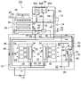
図1は、本発明の第1の実施の形態の電子機器の冷却システム10を示した概念図である。
(First embodiment)
FIG. 1 is a conceptual diagram showing a
図1に示すように、建屋12内には、サーバルーム14が形成される。そして、サーバルーム14の床面の裏側には、床下チャンバ22が形成される。サーバルーム14の床面は、不図示の複数の吹出口が配置され、後記する空調機78(図3参照)からの冷風が床下チャンバ22を通って床面からサーバルーム14に吹き出される。吹出口は、好ましくはサーバ28の前面側近傍に配置され、吹き出された冷風がサーバ28に供給されることによって、サーバ28が効率よく冷却される。尚、建屋12の構成は図1で示したものに限定するものではなく、例えばサーバルーム14を複数の部屋に仕切ったり、複数階にわたってサーバルーム14を設けたりしたりしてもよい。
As shown in FIG. 1, a
図2に示すように、サーバルーム14にはサーバラック26が配設され、サーバラック26に複数のサーバ28が段積み状態で収納される。サーバラック26には、移動用キャスタ24を設けて、移動可能に配置することが好ましい。サーバ28は、ファン30を備えており、矢印32に示すようにサーバルーム14の空気を吸い込んで排気することにより、サーバ28で発生した熱がサーバ28から排出される。尚、サーバ28の配置等の構成は、上記したものに限定されるものではなく、サーバラック26を使用しない形態等も可能である。
As shown in FIG. 2, a
図1に示すように、サーバ28の近傍には蒸発器34が設けられる。蒸発器34の内部には不図示の冷却コイルが設けられ、冷却コイル内を流れる冷媒液体がサーバ28から発生する熱風で蒸発することにより周囲から気化熱を奪いガス化する。これにより、サーバ28自体やサーバ28から排出される熱風を冷却することができる。
As shown in FIG. 1, an
一方、建屋12の屋上には冷却塔38が設けられる。冷却塔38内には、前述した冷媒が流れる螺旋状配管40が収納されており、この螺旋状配管40の上方には、水を螺旋状配管40に散水する散水管42が設けられる。また、散水管42の上方にはファン44が設けられ、外気を冷却塔38側面開口から取り込んで上面開口から排出することで、散水される水と取り込まれた外気とのカウンタカレントが形成され、散水される水が冷却される。ファン44にはインバータ43が設置され、このインバータ43が後述の制御装置72に電気的に接続される。制御装置72は、冷却塔38の出口の液冷媒の温度、圧力を測定する温度センサ45、圧力センサ47に接続され、これらの測定値に基づいてファン44の回転数を制御する。例えば、温度センサ45の測定値が設定温度になるようにファン44の回転数を制御する。
On the other hand, a
冷却塔38の螺旋状配管40には戻り配管46と供給配管48が接続される。戻り配管46及び供給配管48は床下チャンバ22を通ってサーバルーム14に配設された蒸発器34に接続される。したがって、蒸発器34でガス化した冷媒ガスは戻り配管46を通ることによって、上方に配置された冷却塔38に自然に戻され、冷却塔38によって冷却されて凝縮した後、その液化した冷媒液体が供給配管48を通ることによって、下方に配置された蒸発器34に自然に送液される。これにより、冷却塔38と蒸発器34との間には冷媒が自然循環する自然循環ライン(第1の循環ラインに相当)、即ち、内部に冷媒を封入した無動力のヒートパイプが構築される。この自然循環ラインでは、サーバ28からの発熱量が大きくなって高温の冷媒ガスを形成できることで、冷媒ガスを凝縮する冷却温度を高めに設定することができ、冷却塔38による冷却能力でも冷媒ガスを凝縮することができる。係る構成において、近年のサーバ28からの発熱量の急速な上昇により、サーバ28から発生(排出)される高温の熱を高温状態のままで蒸発器34を流れる冷媒と直熱熱交換して冷媒の蒸発を促進することにより、蒸発器34よりも高所に設置された冷却塔38へ蒸発した冷媒ガスを輸送する輸送動力を得ることができる。使用される冷媒としては、フロン、あるいは代替えフロンとしてのHFC(ハイドロフロロカーボン)等を使用することができる。また、大気圧よりも低い圧力で使用するならば、水を使用することも可能である。ここで、冷媒と表現する場合には、ガス状態の冷媒ガスと、液体状態の冷媒液体の両方を含むものであり、図1には、冷媒ガスの流れ方向を白矢印で示し、冷媒液体の流れ方向を黒矢印で示した。
A
蒸発器34には、サーバ28から排出された熱風が蒸発器34で冷却された後の風の温度を測定する温度センサ50が設けられると共に、冷却コイル36の入口には、冷却コイル36に供給する冷媒の供給流量を調整するための膨張弁52が設けられる。そして、温度センサ50による測定温度に基づいて膨張弁52の開度が自動調整される。これにより、蒸発器34で冷却された後の風の温度が設定温度よりも低くなり過ぎた場合には、膨張弁52の開度が絞られて冷媒の供給流量が減少される。
The
以上は外気温度が低い冬場の運転方法であるが、冬場と夏場で運転方法が異なる。次に夏場の運転方法を述べる。 The above is the driving method in winter when the outside air temperature is low, but the driving method is different in winter and summer. Next, the driving method in summer is described.
戻り配管58には圧縮機54が設けられる。圧縮機54の位置は本実施例では屋上であるが、屋上以外の例えばサーバルーム14内でも良い。圧縮機54は前述の冷媒を圧縮する装置であり、例えば、二段の羽根車54A、54Bをモータ54Cで高速回転させ、その遠心力で冷媒を圧縮する遠心圧縮機が用いられる。また、遠心圧縮機に限らず、ロータリー圧縮機、スクロール圧縮機でもよい。
The
圧縮機54の入口には、戻り配管46から分岐された分岐戻り配管58が接続される。また、圧縮機54の出口には分岐供給配管60が接続され、この分岐供給配管60が戻り配管46に分岐戻り配管58よりも下流側で接続される。これらの分岐戻り配管58、分岐供給配管60と、前述の戻り配管46、供給配管48とによって、冷媒の循環ライン(第2の循環ラインに相当)が形成され、圧縮機54、蒸発器34を含む冷凍サイクルが構築される。これにより、蒸発器34で蒸発した冷媒ガスは圧縮機54に導入され、圧縮機54で圧縮された後、冷却塔38で冷却されて凝縮され、蒸発器34に供給される。
A
供給配管48には、気液分離装置62が配設されている。気液分離装置62は、凝縮後の冷媒液体から冷媒ガスを確実に分離し、蒸発器34に冷媒液体を確実に送液するためのものであり、気液分離装置62で分離された冷媒ガスは、送気配管64を介して圧縮機54の中間部、即ち一段目の羽根車54Aと二段目の羽根車54Bとの間に供給される。尚、図1は、エコノマイザサイクルを適用した例であるが、これに限定するものではない。
A gas /
分岐戻り配管58、分岐供給配管60及び戻り配管46にはそれぞれ、開閉弁66、68、70が設けられる。また、気液分離装置62の入口側に弁67が設けられると共に、気液分離装置62のバイパス配管63に弁69が設けられる。開閉弁66〜70は制御装置72に接続されており、この制御装置72によって開閉弁66〜70の開閉操作が行われる。この開閉弁66〜70を開閉操作することによって、冷媒ガスの流れが切り替えられ、冷媒ガスが圧縮機54を通るか否かが選択される。すなわち、第1の循環ラインと第2の循環ラインとの切り替えが行われる。
The
制御装置72は、外気の温湿度を測定する外気センサ74に接続され、この外気センサ74の測定値に基づいて開閉弁66〜70を開閉操作する。例えば、外気の温度が低く、冷却塔38の冷却能力が大きい場合には、開閉弁66〜68を閉じて開閉弁69、70を開き、冷却塔38のみに冷媒ガスが流れるように制御する。反対に外気の温度が高く、冷却塔38の能力が不足する場合には、開閉弁69、70を閉じて開閉弁66〜68を開き、冷媒ガスが圧縮機54に流れるように制御する。これにより、例えば冬場等のように冷却塔38の冷却能力が高いときには、冷却塔38のみを利用する自然循環を行うことによって、コストを削減することができる。反対に、夏場等のように冷却塔38のみでは冷媒の冷却能力が不足する場合には、冷媒ガスを圧縮機54に流すことによって冷凍サイクルを構築するので、蒸発器34で十分な冷却を行うことができる。これにより、冷媒ガスを凝縮させるのに必要な冷熱負荷に応じてランニングコストを最も小さくすることができ、各種の冷却態様を取ることが可能となる。
The
自然循環と冷凍サイクルとの具体的な切替制御方法としては、以下の(1)〜(3)が考えられる。 The following (1) to (3) are conceivable as specific switching control methods between the natural circulation and the refrigeration cycle.
(1)外気の湿球温度、比エンタルピーによる切替方法
外気センサ74で外気の温度と湿度を計測し、それを基に、制御装置72が、外気の湿球温度あるいは外気の比エンタルピーを計算する。そして、計算した湿球温度あるいは比エンタルピーが、設定した圧縮機54の運転開始の設定値よりも大きい場合に、圧縮機54を運転して冷凍サイクル運転を行う。また、計算した湿球温度あるいは比エンタルピーが、設定した圧縮機54の運転停止の設定値よりも小さい場合に自然循環運転を行う。尚、運転が頻繁に切り替わらないように、圧縮機54の運転開始の設定値は圧縮機54の運転停止の設定値よりも大きくするとよい。
(1) Switching method by outside air wet bulb temperature and specific enthalpy The
(2)冷却負荷(あるいは冷媒流量)による切替方法
制御装置72は、冷媒の質量流量と液冷媒とガス冷媒の比エンタルピーの差により冷却負荷を求める。冷媒の質量流量は、冷媒の流量と比重により求め、その冷媒の流量は、図1に示すように、供給配管48にオリフィス71を設けると共に、そのオリフィス71の前後の差圧を差圧計73によって測定することによって求める。一方、液冷媒とガス冷媒との比エンタルピーは、それぞれの圧力と温度(すなわち、温度センサ45、圧力センサ47、温度センサ75、圧力センサ77)によって求める。制御装置72は、このように求めた冷却負荷と、外気センサ74で測定した温度と湿度から求めた外気の湿球温度との組み合わせによって図4に示す如く切替制御を行う。図4において、L1は圧縮機54の運転ラインであり、L2は圧縮機54の停止ラインであってL1よりも外側(湿球温度または冷却負荷が大きくなる側)に設定される。この例では、L1よりも内側の範囲Xにおいて圧縮機54を停止しておく。そして、L1を超えた際に圧縮機54の運転を開始し、L2よりも外側の範囲Yにおいて、定格の冷凍能力で圧縮機54を運転する。そして、L2よりも小さくなった際に、圧縮機54を停止する。
(2) Switching method by cooling load (or refrigerant flow rate) The
尚、外気の湿球温度の代わりに外気の比エンタルピーでもよい。また、多少精度が悪くなるが、冷却負荷の代わりに冷媒流量を用いてもよい。冷媒流量を用いる場合は、精度が悪くなった分の余裕をみて切り替えればよい。 The specific enthalpy of the outside air may be used instead of the wet bulb temperature of the outside air. Further, although the accuracy is somewhat deteriorated, the refrigerant flow rate may be used instead of the cooling load. When the refrigerant flow rate is used, switching may be performed with an allowance for the deterioration in accuracy.
(3)冷却塔38の出口の圧力、温度による切替方法
自然循環から冷凍サイクルへの切替は、ファン44が最大回転数で、且つ、冷却塔38の出口の液冷媒の温度(すなわち温度センサ45の測定値)が、ある設定温度よりも大きい場合に行う。また、冷凍サイクルから自然循環への切替は、冷却塔38の出口の液冷媒の圧力と温度について、予め、切替を行うテーブルを用意しておく。すなわち、それぞれの圧力値について、切替制御を行う温度のテーブルを用意しておく。そして、圧力センサ47の測定値に基づいて、切替制御を行う切替温度を求め、温度センサ45の測定値が切替温度よりも小さい場合に、冷凍サイクルから自然循環への切替制御を行う。
(3) Switching method by pressure and temperature at the outlet of the
上記の(1)〜(3)のいずれかの方法により自然循環と冷凍サイクルとの切替制御を行うことが好ましい。 It is preferable to perform switching control between the natural circulation and the refrigeration cycle by any one of the methods (1) to (3).
以上説明したように第1の実施形態の冷却システム10によれば、発熱量が大きいサーバ28の近傍に設けた蒸発器34と、それよりも高所に設けた冷却塔38との間を冷媒が自然循環する冷却システムを構築したので、サーバ28を小さなランニングコストで冷却することができる。
As described above, according to the
また、第1の実施形態によれば、冷媒ガスの流れを圧縮機54に切り替えるようにしたので、蒸発器34や圧縮機54を含む圧縮式の冷凍サイクルを構築することができ、自然循環の冷却システムで冷却量が不足した際に圧縮式の冷凍サイクルによって冷却量を確保することができる。
Further, according to the first embodiment, since the flow of the refrigerant gas is switched to the
さらに、第1の実施形態によれば、自然循環の冷却システムで用いられる冷媒を圧縮式の冷凍システムの冷媒としても兼用することによって、熱交換器が不要になり、熱交換器等を用いた場合のような熱交換に伴うロスを無くすことができ、熱効率を向上させることができる。 Furthermore, according to the first embodiment, the refrigerant used in the natural circulation cooling system is also used as the refrigerant in the compression refrigeration system, thereby eliminating the need for a heat exchanger and using a heat exchanger or the like. Loss associated with heat exchange as in the case can be eliminated, and thermal efficiency can be improved.
(第2の実施の形態)
図3は、本発明の第2の実施の形態の電子機器の冷却システム100を示した概念図である。尚、第1の実施の形態と同じ部材及び構成について省略する。
(Second Embodiment)
FIG. 3 is a conceptual diagram showing a
第2の実施の形態の冷却システム100は、第1の実施の形態の冷却システム10の構成に、サーバルーム14を冷却するための空調機78を設け、空調機78の冷熱源として前述の冷媒を使用するようにしたものである。
The
即ち、図3に示すように、サーバルーム14に隣接して機械室80が設けられ、機械室80に空調機78が設置される。空調機78の吸込口には吸込ダクト81が接続されており、この吸込ダクト81は、サーバルーム14と機械室80とを仕切る隔壁82を貫通してサーバルーム14まで延設されている。また、空調機78の吹出口には、吹出ダクト83が接続されており、この吹出ダクト83は隔壁82を貫通して床下チャンバ22まで延設されている。したがって、空調機78の送風機86を駆動することによって、サーバルーム14の空気が吸込ダクト81を介して空調機78に取り込まれ、冷却部84によって冷却された後、吹出ダクト83を介して床下チャンバ22に吹き出され、床面からサーバルーム14に吹き出される。その際、床面の吹出口をサーバ28の前面(蒸発器34の反対側)の近傍に形成することによって、床面から吹き出したエアがサーバ28に吸い込まれるように構成することが好ましい。空調機78の冷却部84には、戻り配管46から分岐された空調用戻り配管88と、供給配管48から分岐された空調用供給配管90とが接続され、冷媒が冷却部84を循環するように構成される。
That is, as shown in FIG. 3, a
上記の如く構成された第2の実施の形態の冷却システム100によれば、上記した第1の実施の形態の効果に加えて以下の効果を発揮することができる。即ち、上述した冷媒を、サーバルーム14を冷風で冷却するための空調機78の冷熱源として使用するようにしたので、空調機78を運転するためのランニングコストをも低減することができる。また、サーバ28を冷却する蒸発器34と併用することにより、従来方式(特開2004-232927に示される、床吹き出し空調で全体の空気を循環して空調する方式)の空調システムに比べ、サーバルーム14内での熱溜まり(局所的高温部位)の発生を抑制でき、全体を空調する空調機78からの給気温度を高温化することが可能となる。よって、本実施の形態では従来方式に比べて、蒸発温度が高くてよく、冷却塔38の能力を十分に活用することができる。したがって、自然循環ラインの冷媒を空調機78の冷却部84に供給することは、空調機78の省エネと、冷却塔38の能力発揮の両方に寄与する。
According to the
尚、上記した第1、第2の実施の形態における冷却システム10、100は、電子機器としてサーバ28の例で説明したが、本発明は、それ自体からの発熱量が大きな電子機器の全てに適用することができる。
Although the
10、100…冷却システム、12…建屋、14…サーバルーム、22…床下チャンバ、24…キャスタ、26…サーバラック、28…サーバ、30…サーバのファン、32…熱風、34…蒸発器、38…冷却装置、40…螺旋状配管、42…螺旋状配管、43…インバータ、44…冷水装置のファン、45…温度センサ、46…戻り配管、47…圧力センサ、48…供給配管、50…温度センサ、52…膨張弁、54…圧縮機、58…分岐戻り配管、60…分岐供給配管、62…気液分離装置、64…送気配管、66〜70…開閉弁、71…オリフィス、72…制御装置、73…差圧センサ、74…外気センサ、75…温度センサ、77…圧力センサ、78…空調機、79…ファン、80…機械室、82…隔壁、84…冷却部、86…ファン、88…空調用供給配管、90…空調用戻り配管
DESCRIPTION OF SYMBOLS 10,100 ... Cooling system, 12 ... Building, 14 ... Server room, 22 ... Under floor chamber, 24 ... Caster, 26 ... Server rack, 28 ... Server, 30 ... Server fan, 32 ... Hot air, 34 ... Evaporator, 38 DESCRIPTION OF SYMBOLS ... Cooling device, 40 ... Spiral piping, 42 ... Spiral piping, 43 ... Inverter, 44 ... Cooling water fan, 45 ... Temperature sensor, 46 ... Return piping, 47 ... Pressure sensor, 48 ... Supply piping, 50 ...
Claims (4)
前記複数の電子機器に近接してそれぞれ設けられ、前記電子機器から発生する熱で冷媒を気化させることにより該電子機器を冷却する蒸発器と、
前記蒸発器よりも高所に設けられ、前記気化した冷媒を外気によって冷却して凝縮させる冷却塔と、
前記気化した冷媒を圧縮する圧縮機と、
前記蒸発器と前記冷却塔との間で前記冷媒が自然循環するように接続された第1の循環ラインと、
前記第1の循環ラインを分岐させて前記圧縮機に接続することによって、前記蒸発器と前記圧縮機を含む冷凍サイクルを前記冷媒が循環するように接続された第2の循環ラインと、
前記第1の循環ラインと前記第2の循環ラインに流す前記冷媒の冷媒量を開閉弁の開閉により切り替える切換手段と、
前記切替手段を制御する制御手段と、
外気の温湿度を測定する外気センサと、を有し、
前記制御手段は、前記外気センサの測定結果及び前記冷媒の冷媒流量に基づき前記切替手段を開閉操作することを特徴とする電子機器の冷却システム。 An equipment room with a plurality of electronic devices,
An evaporator that is provided in the vicinity of each of the plurality of electronic devices and cools the electronic devices by evaporating a refrigerant with heat generated from the electronic devices;
A cooling tower that is provided at a higher position than the evaporator and cools and condenses the vaporized refrigerant with outside air;
A compressor for compressing the vaporized refrigerant;
A first circulation line connected so that the refrigerant naturally circulates between the evaporator and the cooling tower;
A second circulation line connected so that the refrigerant circulates in the refrigeration cycle including the evaporator and the compressor by branching the first circulation line and connecting to the compressor;
Switching means for switching a refrigerant amount of the refrigerant flowing through the first circulation line and the second circulation line by opening and closing an on-off valve;
Control means for controlling the switching means;
An outside air sensor for measuring the temperature and humidity of the outside air,
The electronic device cooling system, wherein the control means opens and closes the switching means based on a measurement result of the outside air sensor and a refrigerant flow rate of the refrigerant.
前記複数の電子機器に近接してそれぞれ設けられ、前記電子機器から発生する熱で冷媒を気化させることにより該電子機器を冷却する蒸発器と、
前記蒸発器よりも高所に設けられ、前記気化した冷媒を外気によって冷却して凝縮させる冷却塔と、
前記気化した冷媒を圧縮する圧縮機と、
前記蒸発器と前記冷却塔との間で前記冷媒が自然循環するように接続された第1の循環ラインと、
前記第1の循環ラインを分岐させて前記圧縮機に接続することによって、前記蒸発器、前記圧縮機を含む冷凍サイクルを前記冷媒が循環するように接続された第2の循環ラインと、
前記気化した冷媒の流れを、前記第1の循環ラインと前記第2の循環ラインとで切り替える切換手段と、
前記切替手段を制御する制御手段と、
前記冷却塔の出口の冷媒の温度を測定する温度センサと、
前記冷却塔の出口の冷媒の圧力を測定する圧力センサと、
前記制御手段は、前記温度センサ及び前記圧力センサの測定値に基づき前記切替手段を開閉操作することを特徴とする電子機器の冷却システム。 An equipment room with a plurality of electronic devices,
An evaporator that is provided in the vicinity of each of the plurality of electronic devices and cools the electronic devices by evaporating a refrigerant with heat generated from the electronic devices;
A cooling tower that is provided at a higher position than the evaporator and cools and condenses the vaporized refrigerant with outside air;
A compressor for compressing the vaporized refrigerant;
A first circulation line connected so that the refrigerant naturally circulates between the evaporator and the cooling tower;
A second circulation line connected so that the refrigerant circulates in the refrigeration cycle including the evaporator and the compressor by branching the first circulation line and connecting to the compressor;
Switching means for switching the flow of the vaporized refrigerant between the first circulation line and the second circulation line;
Control means for controlling the switching means;
A temperature sensor for measuring the temperature of the refrigerant at the outlet of the cooling tower;
A pressure sensor for measuring the pressure of the refrigerant at the outlet of the cooling tower;
The electronic device cooling system, wherein the control means opens and closes the switching means based on the measured values of the temperature sensor and the pressure sensor.
Priority Applications (1)
| Application Number | Priority Date | Filing Date | Title |
|---|---|---|---|
| JP2012093212A JP2012146331A (en) | 2012-04-16 | 2012-04-16 | Cooling system for electronic equipment |
Applications Claiming Priority (1)
| Application Number | Priority Date | Filing Date | Title |
|---|---|---|---|
| JP2012093212A JP2012146331A (en) | 2012-04-16 | 2012-04-16 | Cooling system for electronic equipment |
Related Parent Applications (1)
| Application Number | Title | Priority Date | Filing Date |
|---|---|---|---|
| JP2008032101A Division JP5041343B2 (en) | 2008-02-13 | 2008-02-13 | Electronic equipment cooling system |
Publications (1)
| Publication Number | Publication Date |
|---|---|
| JP2012146331A true JP2012146331A (en) | 2012-08-02 |
Family
ID=46789771
Family Applications (1)
| Application Number | Title | Priority Date | Filing Date |
|---|---|---|---|
| JP2012093212A Pending JP2012146331A (en) | 2012-04-16 | 2012-04-16 | Cooling system for electronic equipment |
Country Status (1)
| Country | Link |
|---|---|
| JP (1) | JP2012146331A (en) |
Cited By (4)
| Publication number | Priority date | Publication date | Assignee | Title |
|---|---|---|---|---|
| JP2014229065A (en) * | 2013-05-22 | 2014-12-08 | 株式会社Nttファシリティーズ | Device cooling system and control method thereof |
| WO2015075916A1 (en) * | 2013-11-20 | 2015-05-28 | 日本電気株式会社 | Electronic apparatus enclosure device and electronic apparatus cooling system |
| CN111613591A (en) * | 2020-06-01 | 2020-09-01 | 福清市凯联电子科技有限公司 | A chip cooling device that can collect condensed water |
| US11226130B2 (en) | 2017-01-16 | 2022-01-18 | Nec Corporation | Valve control device, cooling device, and valve control method |
Citations (6)
| Publication number | Priority date | Publication date | Assignee | Title |
|---|---|---|---|---|
| JPH02233923A (en) * | 1989-03-06 | 1990-09-17 | Mitsui Ginkou:Kk | Central direct expansion air conditioning device |
| JPH09159210A (en) * | 1995-12-04 | 1997-06-20 | Takenaka Komuten Co Ltd | Cooling system |
| JP2001041503A (en) * | 1999-08-03 | 2001-02-16 | Mitsubishi Electric Corp | Case cooling system for communication base station |
| JP2004211998A (en) * | 2003-01-07 | 2004-07-29 | Takasago Thermal Eng Co Ltd | Air conditioning equipment |
| JP2004233030A (en) * | 2002-12-02 | 2004-08-19 | Denso Corp | Cooling system |
| US20060232945A1 (en) * | 2005-04-18 | 2006-10-19 | International Business Machines Corporation | Apparatus and method for facilitating cooling of an electronics rack employing a heat exchange assembly mounted to an outlet door cover of the electronics rack |
-
2012
- 2012-04-16 JP JP2012093212A patent/JP2012146331A/en active Pending
Patent Citations (6)
| Publication number | Priority date | Publication date | Assignee | Title |
|---|---|---|---|---|
| JPH02233923A (en) * | 1989-03-06 | 1990-09-17 | Mitsui Ginkou:Kk | Central direct expansion air conditioning device |
| JPH09159210A (en) * | 1995-12-04 | 1997-06-20 | Takenaka Komuten Co Ltd | Cooling system |
| JP2001041503A (en) * | 1999-08-03 | 2001-02-16 | Mitsubishi Electric Corp | Case cooling system for communication base station |
| JP2004233030A (en) * | 2002-12-02 | 2004-08-19 | Denso Corp | Cooling system |
| JP2004211998A (en) * | 2003-01-07 | 2004-07-29 | Takasago Thermal Eng Co Ltd | Air conditioning equipment |
| US20060232945A1 (en) * | 2005-04-18 | 2006-10-19 | International Business Machines Corporation | Apparatus and method for facilitating cooling of an electronics rack employing a heat exchange assembly mounted to an outlet door cover of the electronics rack |
Cited By (9)
| Publication number | Priority date | Publication date | Assignee | Title |
|---|---|---|---|---|
| JP2014229065A (en) * | 2013-05-22 | 2014-12-08 | 株式会社Nttファシリティーズ | Device cooling system and control method thereof |
| WO2015075916A1 (en) * | 2013-11-20 | 2015-05-28 | 日本電気株式会社 | Electronic apparatus enclosure device and electronic apparatus cooling system |
| CN105746008A (en) * | 2013-11-20 | 2016-07-06 | 日本电气株式会社 | Electronic apparatus enclosure device and electronic apparatus cooling system |
| JPWO2015075916A1 (en) * | 2013-11-20 | 2017-03-16 | 日本電気株式会社 | Electronic device housing apparatus and electronic device cooling system |
| CN105746008B (en) * | 2013-11-20 | 2017-11-17 | 日本电气株式会社 | Electronic equipment storage device and electronic device cooling system |
| US10182517B2 (en) | 2013-11-20 | 2019-01-15 | Nec Corporation | Electronic apparatus enclosure device and electronic apparatus cooling system |
| US11226130B2 (en) | 2017-01-16 | 2022-01-18 | Nec Corporation | Valve control device, cooling device, and valve control method |
| CN111613591A (en) * | 2020-06-01 | 2020-09-01 | 福清市凯联电子科技有限公司 | A chip cooling device that can collect condensed water |
| CN111613591B (en) * | 2020-06-01 | 2020-11-27 | 福清市凯联电子科技有限公司 | A chip cooling device that can collect condensed water |
Similar Documents
| Publication | Publication Date | Title |
|---|---|---|
| JP5041343B2 (en) | Electronic equipment cooling system | |
| JP4780479B2 (en) | Electronic equipment cooling system | |
| US9404679B2 (en) | Cooling system and cooling method | |
| JP5041342B2 (en) | Electronic equipment cooling system | |
| JP5024675B2 (en) | Electronic device cooling system and cooling method | |
| US20110259573A1 (en) | Cooling system | |
| JP2011237887A (en) | Cooling method and cooling system for electronic equipment | |
| JP2009216295A (en) | Cooling system of electronic device and its operating method | |
| JP2012007865A (en) | Cooling system | |
| JP5921931B2 (en) | Air conditioning system | |
| JP2011171499A (en) | Cooling method and cooling system of electronic apparatus | |
| JP5491923B2 (en) | Electronic equipment cooling system | |
| WO2002077535A1 (en) | Air conditioner and method of installing the air conditioner | |
| JP2010160533A (en) | Server storage device | |
| JP2013257889A (en) | Cooling system of electronic equipment | |
| JP2012146331A (en) | Cooling system for electronic equipment | |
| JP2009194094A (en) | Electronic equipment cooling system | |
| JP2009193244A (en) | Electronic equipment cooling system | |
| JP4274075B2 (en) | Refrigerator and vending machine | |
| JP2011155301A (en) | Cooling system for electronic apparatus | |
| JP2011163758A (en) | Cooling system for electronic device | |
| JP4941676B2 (en) | Air conditioning system | |
| JP2012142026A (en) | Cooling system for electronic apparatus | |
| JP4605488B2 (en) | Electronic equipment cooling system | |
| JP2013003636A (en) | Server rack cooling apparatus |
Legal Events
| Date | Code | Title | Description |
|---|---|---|---|
| A621 | Written request for application examination |
Free format text: JAPANESE INTERMEDIATE CODE: A621 Effective date: 20120418 |
|
| A977 | Report on retrieval |
Free format text: JAPANESE INTERMEDIATE CODE: A971007 Effective date: 20130308 |
|
| A131 | Notification of reasons for refusal |
Free format text: JAPANESE INTERMEDIATE CODE: A131 Effective date: 20130313 |
|
| A521 | Written amendment |
Free format text: JAPANESE INTERMEDIATE CODE: A523 Effective date: 20130424 |
|
| A711 | Notification of change in applicant |
Free format text: JAPANESE INTERMEDIATE CODE: A712 Effective date: 20130612 |
|
| A02 | Decision of refusal |
Free format text: JAPANESE INTERMEDIATE CODE: A02 Effective date: 20131107 |