JP2012148332A - Method of manufacturing tailored blank material - Google Patents
Method of manufacturing tailored blank material Download PDFInfo
- Publication number
- JP2012148332A JP2012148332A JP2011010475A JP2011010475A JP2012148332A JP 2012148332 A JP2012148332 A JP 2012148332A JP 2011010475 A JP2011010475 A JP 2011010475A JP 2011010475 A JP2011010475 A JP 2011010475A JP 2012148332 A JP2012148332 A JP 2012148332A
- Authority
- JP
- Japan
- Prior art keywords
- cutting
- welding
- cut
- line
- blank material
- Prior art date
- Legal status (The legal status is an assumption and is not a legal conclusion. Google has not performed a legal analysis and makes no representation as to the accuracy of the status listed.)
- Pending
Links
- 239000000463 material Substances 0.000 title claims abstract description 118
- 238000004519 manufacturing process Methods 0.000 title claims abstract description 14
- 238000005520 cutting process Methods 0.000 claims abstract description 68
- 238000003466 welding Methods 0.000 claims abstract description 59
- 238000010008 shearing Methods 0.000 claims description 3
- 230000003466 anti-cipated effect Effects 0.000 abstract 1
- 238000000034 method Methods 0.000 description 11
- 229910000831 Steel Inorganic materials 0.000 description 6
- 239000010959 steel Substances 0.000 description 6
- 230000006872 improvement Effects 0.000 description 4
- 230000008569 process Effects 0.000 description 4
- 210000001503 joint Anatomy 0.000 description 3
- 238000000465 moulding Methods 0.000 description 3
- CURLTUGMZLYLDI-UHFFFAOYSA-N Carbon dioxide Chemical compound O=C=O CURLTUGMZLYLDI-UHFFFAOYSA-N 0.000 description 2
- 239000011324 bead Substances 0.000 description 2
- 230000007547 defect Effects 0.000 description 2
- 101100008048 Caenorhabditis elegans cut-4 gene Proteins 0.000 description 1
- 101100008049 Caenorhabditis elegans cut-5 gene Proteins 0.000 description 1
- 230000009471 action Effects 0.000 description 1
- 238000005452 bending Methods 0.000 description 1
- 229910002092 carbon dioxide Inorganic materials 0.000 description 1
- 239000001569 carbon dioxide Substances 0.000 description 1
- 238000007796 conventional method Methods 0.000 description 1
- 238000010586 diagram Methods 0.000 description 1
- 238000005304 joining Methods 0.000 description 1
- 238000003698 laser cutting Methods 0.000 description 1
- 239000002184 metal Substances 0.000 description 1
- 230000004048 modification Effects 0.000 description 1
- 238000012986 modification Methods 0.000 description 1
- 238000003825 pressing Methods 0.000 description 1
- 230000006641 stabilisation Effects 0.000 description 1
- 238000011105 stabilization Methods 0.000 description 1
Images


Landscapes
- Shearing Machines (AREA)
- Laser Beam Processing (AREA)
Abstract
【課題】突き合わせて接合する二枚のブランク材同士の隙間を溶接線方向にわたり均一化し、溶接線が曲線状の場合であっても溶接精度・品質を確保できるテーラードブランク材の製造方法を提供する。
【解決手段】切端材S1,S2分の切り代を見込んである二枚のブランク材P11,P12を予め用意し、溶接時における突き合わせ部位の両側で切端材S1,S2分の切り代だけ互いにオーバーラップするように重ね合わせた状態で上記突き合わせ部位に相当する部分を切断線8としてブランク材P11,P12を同時に切断する。切端材S1,S2を除いた切断後のそれぞれの板材P1,P2の切断線8に相当する切り口3,4同士を突き合わせて、当該突き合わせ部位を溶接線としてレーザ溶接を施す。
【選択図】図1The present invention provides a method for producing a tailored blank material that can uniform a gap between two blank materials to be joined and joined in the direction of the weld line and ensure welding accuracy and quality even when the weld line is curved. .
SOLUTION: Two blank materials P11 and P12 for which cutting margins for cutting edges S1 and S2 are anticipated are prepared in advance, and the cutting margins for cutting edges S1 and S2 are mutually exceeded on both sides of the abutting portion during welding. The blanks P11 and P12 are simultaneously cut with the portion corresponding to the abutting portion as a cutting line 8 in a state of being overlapped so as to be wrapped. Cut ends 3 and 4 corresponding to the cutting lines 8 of the respective plate materials P1 and P2 after cutting excluding the cut ends S1 and S2 are butted together, and laser welding is performed using the butted portion as a welding line.
[Selection] Figure 1
Description
本発明は、異なる種類の板材を組み合わせて溶接接合してなるテーラードブランク材の製造方法に関する。 The present invention relates to a method for manufacturing a tailored blank formed by welding different types of plate materials in combination.
自動車の車体部品等の成形要素として、板厚や材質あるいは強度が異なる複数の板材(鋼板等の金属薄板)同士を突き合わせてレーザ溶接等にて溶接接合することで一枚のものとしたテーラードブランク材が用いられることがある。特に板厚が異なる鋼板同士を突き合わせて溶接接合したものは差厚鋼板または差厚ブランク材とも称されている。このようなテーラードブランク材を用いて車体部品を所要形状にプレス成形することにより、必要な部位に必要な板厚、材質あるいは強度を持たせることができるとともに、その車体部品自体ひいては車体全体の軽量化に寄与できるとされている。 Tailored blanks made by molding a plurality of plate materials (thin metal plates such as steel plates) with different thicknesses, materials, or strengths and joining them together by laser welding or the like as molding elements for automobile body parts Materials may be used. In particular, steel plates having different thicknesses that are joined together and welded together are also called differential thickness steel plates or differential thickness blank materials. By press-molding car body parts into the required shape using such a tailored blank material, the necessary parts can have the necessary thickness, material, or strength, and the car body parts themselves and thus the weight of the entire car body It is said that it can contribute to
そして、例えば板厚が異なる二枚の板材同士を突き合わせて溶接接合してなるテーラードブランク材を製造するには、別々に切断した一方の板材と他方の板材の切り口同士を突き合わせた上でレーザ溶接等の突き合わせ溶接を施すことを基本としていて、特許文献1の図1,2には切端材の発生を伴う板取り方法と切端材の発生を伴わない板取り方法とが開示されている。
For example, in order to manufacture a tailored blank material in which two plate materials having different plate thicknesses are butted and joined together, laser welding is performed after the cut surfaces of one plate material and the other plate material which are cut separately are butted together. 1 and 2 of
しかしながら、上記特許文献1に代表されるような従来の方法において、別々に切断した(多くの場合に別々の切断刃で切断した)一方の板材と他方の板材の切り口同士を単に突き合わせただけでは、当該突き合わせ部位に隙間が発生したり、あるいは溶接線方向でその隙間が不均一になりやすく、その後の溶接精度および溶接品質が安定せず、未溶着などの溶接不良が発生する場合がある。この傾向は、特に双方の板材同士の突き合わせ部位であるところの溶接線が一直線状以外の場合、特に溶接線が曲線状のものである場合に顕著となるほか、それぞれの板材を個別に用意した別々の切断型にて切断する必要があるために、設備費の高騰を招くこととなって好ましくない。
However, in the conventional method as typified by the above-mentioned
また、特許文献1の図1に記載された方法では、切端材の発生がない点で確かに材料歩留まりの向上の上で有効であるが、先に述べたように双方の板材同士の突き合わせ部位であるところの溶接線が一直線状の場合のみ適用できるものであり、溶接線が一直線状以外の場合、特に溶接線が曲線等のように複雑形状のものである場合には、溶接精度および溶接品質の向上の上でなおも改善の余地を残している。
Further, the method described in FIG. 1 of
本発明はこのような課題に着目してなされたものであり、切端材の発生を容認することで溶接精度および溶接品質の向上を優先し、特に溶接線が曲線等のように一直線状以外の複雑形状の場合であっても安定した溶接精度および溶接品質を確保できるように考慮されたテーラードブランク材の製造方法を提供するものである。 The present invention has been made paying attention to such a problem, and gives priority to the improvement of welding accuracy and welding quality by accepting the generation of cutting material, and in particular, the welding line is other than a straight line such as a curve. It is an object of the present invention to provide a tailored blank material manufacturing method that is considered so as to ensure stable welding accuracy and welding quality even in the case of a complex shape.
請求項1に記載の発明は、少なくとも二枚の板材を突き合わせて溶接接合してなるテーラードブランク材を製造する方法であって、切端材分の切り代を見込んである独立した二枚の板材を予め用意し、溶接時における突き合わせ部位の両側で二枚の板材同士が切端材分の切り代だけ互いにオーバーラップするように重ね合わせた状態で上記突き合わせ部位に相当する部分を切断線として双方の板材を同時に切断し、切端材を除いた切断後のそれぞれの板材の上記切断線に相当する切り口同士を突き合わせて、当該突き合わせ部位を溶接線として溶接を施すことを特徴とするものである。
The invention according to
この場合において、請求項2に記載のように、上記切断線(溶接線)は一直線状以外のもの、例えば曲線状のもののほかV字状やクランク状のものを想定していて、また、溶接方法については、溶接継手として突き合わせ継手を達成できれば、レーザ溶接のほか炭酸ガス溶接あるいはプラズマ溶接、MIG溶接、マッシュシーム溶接等のいずれの方式であっても良い。
In this case, as described in
さらに、二枚の板材の同時切断は、生産性および設備の簡易さを考慮すると、請求項3に記載のように、シャー切断あるいはブランキング等のように共通の切断刃を用いたプレスせん断加工によるものが望ましい。ただし、切断線が複雑な曲線状のものである場合には、請求項4に記載のように、レーザを用いた切断加工としても良い。
Furthermore, in consideration of productivity and simplicity of equipment, the simultaneous cutting of the two plate members is a press shearing process using a common cutting blade such as shear cutting or blanking as described in
したがって、少なくとも請求項1に記載の発明では、重ね合わせた状態で同時に切断した双方の板材の切り口同士を突き合わせた上で溶接を施すことで、溶接線となるべき双方の切り口同士が正確に合致して隙間やその不均一さが発生しにくいものとなることから、溶接精度および溶接品質の安定化につながることになる。
Therefore, in at least the invention described in
請求項1に記載の発明によれば、溶接継手である突き合わせ継手での隙間の発生を抑制して、溶接精度および溶接品質の安定化を図ることができるほか、板材を切断するための切断型も一台で済むので、設備費の低廉化も同時に達成できることになる。 According to the first aspect of the present invention, it is possible to suppress the generation of a gap in the butt joint which is a welded joint, to stabilize the welding accuracy and the welding quality, and to cut the plate material. The cost of equipment can be reduced at the same time.
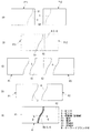
図1〜4は本発明に係るテーラードブランク材の製造方法を実施するためのより具体的な形態を示す図で、特に図1は一枚となったテーラードブランク材Wを得るまでの一連の工程説明図を示している。 1-4 is a figure which shows the more concrete form for enforcing the manufacturing method of the tailored blank material which concerns on this invention, and especially FIG. 1 is a series of processes until the tailored blank material W which became one sheet is obtained. An explanatory diagram is shown.
図1の(D)に示すように、予めブランキングまたはプリカットされて相互に独立している変形矩形状の二枚の板材(例えば鋼板)P1,P2を用意する。図2にも示すように、一方の板材P1は相対的に板厚t1が小さく、他方の板材P2は相対的に板厚t2が大きく、両者の板厚t1,t2の関係はt1<t2の関係となっていて、さらに双方の板材P1,P2の端面には最終的には互いに突き合わされて整合・合致することで溶接線となる突き合わせ面としての曲線状の切り口3または4を個別に形成してある。
As shown in FIG. 1D, two deformed rectangular plate materials (for example, steel plates) P1 and P2 that are blanked or precut in advance and are independent of each other are prepared. As shown in FIG. 2, one plate P1 has a relatively small plate thickness t1, the other plate P2 has a relatively large plate thickness t2, and the relationship between the plate thicknesses t1 and t2 is t1 <t2. In addition, the end faces of both plate materials P1 and P2 are finally abutted against each other and aligned and matched to individually form
そして、図1の(E)および図2,3に示すように、双方の板材P1,P2の切り口3,4同士を突き合わせた上でレーザ溶接に供し、上記切り口3,4同士の突き合わせ部を溶接線として突き合わせ継手の形態をもって連続的にレーザ溶接を施すことにより、板厚の異なる二枚の板材P1,P2からなる矩形平板状のテーラードブランク材Wを得る。なお、図1の(E)の符号Beは、切り口3,4同士の突き合わせ面にレーザ溶接を施すことにより形成されたビード部を示す。
Then, as shown in FIG. 1E and FIGS. 2 and 3, the
こうして得られたテーラードブランク材Wは、例えば自動車の車体部品等のプレス用素材として用いられ、周知のように曲げ加工あるいは絞り成形加工等にて所要の三次元形状に成形されることになる。 The tailored blank W obtained in this way is used, for example, as a pressing material for automobile body parts and the like, and is formed into a required three-dimensional shape by bending or drawing as is well known.
ここで、板厚の異なるそれぞれの板材P1,P2を別々の工程にて且つ別々の切断型にて切断した場合には、切り口3,4同士の合致精度を確保できず、溶接に先立って切り口3,4同士を突き合わせた際に隙間やそのばらつきによる隙間の不均一が発生して、溶接不良が発生する可能性があることは先に述べたとおりである。
Here, when the plate materials P1 and P2 having different plate thicknesses are cut in different processes and with different cutting dies, the matching accuracy between the
そこで、本実施の形態では、双方の板材P1,P2の切り口3,4同士の合致精度を確保するに際して、双方の板材P1,P2の母材同士を重ね合わせた状態で切り口3,4を共通の切断型にて同時に切断することで、それらの切り口3,4同士の合致精度を確保しようとするものである。
Therefore, in the present embodiment, when securing the matching accuracy between the
より具体的には、図1の(A)に示すように、一方の板材P1の母材となる矩形状のブランク材P11として、切り口3となるべき部分の近傍に切端材S1としての切り代を予め見込んである大きさのものを用意し、同様に他方の板材P2の母材となる矩形状のブランク材P12として、切り口4となるべき部分の近傍に切端材S2としての切り代を予め見込んである大きさのものを用意する。
More specifically, as shown in FIG. 1A, as a rectangular blank material P11 that is a base material of one plate material P1, a cutting margin as a cutting material S1 is provided in the vicinity of a portion to be the
そして、これらのブランク材P11,P12同士を重ね合わせた上で、図1の(B)および図4に示すように、共通の切断型5による同時切断に供するものとする。図4に示した切断型5はいわゆるブランキングプレス型と称されるもので、切断刃である固定式の下刃6に対して同じく切断刃である可動式の上刃7が昇降動作することで両者の噛み合いに基づくせん断作用によりブランク材P11,P12を同時切断するものである。なお、下刃6および上刃7側の切刃6a,7aは、共に図1(D)の切り口3,4の形状に合致していて、両者の間に微少なクリアランスが設定されている。
And after these blank materials P11 and P12 are piled up, as shown to (B) and FIG. 4 of FIG. 1, it shall be used for the simultaneous cutting | disconnection by the
双方のブランク材P11,P12同士を重ね合わせるに際しては、例えば図4に示すように、一方のブランク材P11を上側とし、他方のブランク材P12を下側とするとともに、溶接時における突き合わせ部位の両側、すなわち切り口3,4となるべき部位の両側で双方のブランク材P11,P12同士が切端材S1,S2分の切り代だけ互いにオーバーラップするように重ね合わせるものとする。この状態で、下刃6に対して上刃7を下降させて、一方のブランク材P11を落とし側とし、他方のブランク材P12を残り側として、上記切り口3,4に相当する部分を切断線8として双方のブランク材P11,P12を同時に切断(せん断)する。
When the two blank materials P11 and P12 are overlapped with each other, as shown in FIG. 4, for example, one blank material P11 is set as the upper side, the other blank material P12 is set as the lower side, and both sides of the butted portion at the time of welding. That is, it is assumed that the blank materials P11 and P12 are overlapped on both sides of the portion to be the
この場合において、落とし側となる一方のブランク材P11が不安定になりやすいので、必要に応じて一方のブランク材P11を下側からクッションパッド等にて支えたり、あるいは一方のブランク材P11のうち切端材S1となるべき領域を図示外のパッドにて上方から加圧拘束することが望ましい。また、一方のブランク材P11と他方のブランク材12との上下関係は当然のことながら図4とは逆であっても良い。 In this case, one blank material P11 on the dropping side tends to become unstable, so that one blank material P11 is supported by a cushion pad or the like from the lower side as necessary, or one of the blank materials P11 It is desirable to pressurize and restrain the region to be the cut material S1 from above with a pad (not shown). Also, the vertical relationship between one blank material P11 and the other blank material 12 may be reversed from that shown in FIG.
これにより、図1の(B),(C)に示すように、双方のブランク材P11,P12には共通の切断型5による切断線8をもってそれぞれに同じ形状の切り口3,4が形成されたことになり、同時に一方のブランク材P11からは一方の板材P1と切端材S1が、他方のブランク材P12からは他方の板材P2と切端材S2がそれぞれに発生することになる。また、図3に示すように、落とし側となる一方の板材P1の切り口3にはせん断による切り口面の特殊性として下面側に「だれ」が発生するとともに上向きにかえり3aが発生し、同様に、残り側となる他方の板材P2の切り口4には上面側に「だれ」が発生するとともに下向きにかえり4aが発生することになる。
As a result, as shown in FIGS. 1B and 1C, both blank materials P11 and P12 have
この後、先に図1の(D)に基づいて説明したように、切端材S1,S2を除いた切断後のそれぞれの板材P1,P2の上記切断線8に相当する切り口3,4同士を突き合わせて、その突き合わせ部位を溶接線としてレーザ溶接を施し、同図(E)および図2に示すようないわゆる一枚板となったテーラードブランク材Wを得ることになる。なお、当然のことながら、切り口3,4同士の突き合わせに際して双方の板材P1,P2は切断時の姿勢のままで表裏反転しない。 Thereafter, as described above with reference to FIG. 1D, the cut edges 3, 4 corresponding to the cutting line 8 of the respective plate materials P1, P2 after cutting excluding the cut ends S1, S2 are formed. Then, laser welding is performed using the butted portion as a welding line, and a tailored blank material W that is a so-called single plate as shown in FIG. As a matter of course, when the cut ends 3 and 4 are brought into contact with each other, both the plate materials P1 and P2 remain in the posture at the time of cutting and are not reversed.
この場合において、図3に基づいて先に述べたように、レーザ溶接に先立って双方の板材P1,P2の切り口3,4同士を突き合わせた際には、かえり3aが上向きの一方の板材P1の切り口3と、かえり4aが下向きの他方の板材P2の切り口4との組み合わせとなることから、両者の突き合わせ部には容積が比較的小さくて突き合わせ溶接に好適なV形の開先形状が形成されることになる。
In this case, as described above with reference to FIG. 3, when the cut edges 3 and 4 of both the plate materials P1 and P2 are brought into contact with each other prior to laser welding, the
このように本実施の形態によれば、双方の板材P1,P2同士の突き合わせ面となるべき切り口3,4を共通の切断型5にて同時に切断することにより、双方の切り口3,4の合致精度が著しく向上し、両者を突き合わせた際の隙間の発生やその不均一さを大幅に抑制することができる。このことは、レーザ溶接を施した際の溶接不良の発生を大幅に抑制できることにほかならず、溶接精度および溶接品質の大幅な向上が期待できるようになる。
As described above, according to the present embodiment, the
すなわち、レーザ溶接は他の溶接法に比べてレーザ光照射部のエネルギー密度が高く、形成されるビード部Beの幅寸法が小さいため、とかく溶接品質に突き合わせ部での隙間のばらつきの影響を受けやすい傾向にあるが、本実施の形態によれば、双方の板材P1,P2の切り口3,4同士の合致精度ひいては突き合わせ精度が著しく向上することによって、溶接不良の発生を未然に防止することが可能となる。 In other words, laser welding has a higher energy density in the laser beam irradiated portion than other welding methods, and the width of the bead portion Be formed is small, so the welding quality is affected by the gap variation at the butt portion anyway. Although it tends to be easy, according to the present embodiment, it is possible to prevent the occurrence of poor welding by remarkably improving the matching accuracy between the cut edges 3 and 4 of both plate materials P1 and P2, and the matching accuracy. It becomes possible.
ここで、図1に示した形態では、各板材P1,P2の切断線8(溶接線)が曲線状のものである場合について例示しているが、切断線8が一直線状以外の場合、例えば図5の(A)〜(D)に示すように、切断線8が直線同士を組み合わせた屈曲した形状であったり、あるいは直線と曲線を組み合わせた屈曲した形状のものであっても本発明を適用することが可能である。 Here, in the form shown in FIG. 1, the case where the cutting lines 8 (welding lines) of the respective plate materials P1, P2 are curved is illustrated, but when the cutting line 8 is other than a straight line, for example, As shown in FIGS. 5A to 5D, the present invention can be applied even if the cutting line 8 has a bent shape combining straight lines or a bent shape combining straight lines and curves. It is possible to apply.
また、先の形態では、切断線8での切断は共通の切断型5にて同時に切断する方式としているが、これに代えてレーザを用いた切断加工とすることも可能である。例えば切断線8の形状が曲線等の一段と複雑な形状である場合には、例えばNC制御方式のレーザ加工ヘッドまたは産業用ロボットに持たせたレーザ加工ヘッドを切断線8と同様の軌跡のもとで移動させて、重ね合わせた二枚のブランク材P11,P12を同時に切断する方式としても良い。 In the previous embodiment, the cutting line 8 is cut at the same time with the common cutting die 5, but it is also possible to use laser cutting instead. For example, when the shape of the cutting line 8 is a more complicated shape such as a curve, for example, an NC control type laser processing head or a laser processing head held by an industrial robot is based on the same locus as the cutting line 8. It is good also as a system cut | disconnected by, and cut | disconnecting the two blank materials P11 and P12 which overlap | superposed simultaneously.
さらに、先の形態では双方の板材が鋼板である場合の例を示しているが、当然のことながら鋼板以外の同種または異種の板材同士からなるテーラードブランク材にも本発明を適用することができる。 Furthermore, although the example in the case where both plate materials are steel plates is shown in the previous embodiment, the present invention can naturally be applied to tailored blank materials made of the same or different types of plate materials other than steel plates. .
3…切り口
4…切り口
5…ブランキングプレス型(切断型)
6…下刃(切断刃)
7…上刃(切断刃)
8…切断線(溶接線)
P1…板材
P2…板材
P11…ブランク材(母材)
P12…ブランク材(母材)
S1…切端材
S2…切端材
W…テーラードブランク材
3 ...
6 ... Lower blade (cutting blade)
7 ... Upper blade (cutting blade)
8 ... Cutting line (welding line)
P1 ... Plate material P2 ... Plate material P11 ... Blank material (base material)
P12 ... Blank material (base material)
S1 ... Cut material S2 ... Cut material W ... Tailored blank material
Claims (4)
切端材分の切り代を見込んである独立した二枚の板材を予め用意し、
溶接時における突き合わせ部位の両側で二枚の板材同士が切端材分の切り代だけ互いにオーバーラップするように重ね合わせた状態で上記突き合わせ部位に相当する部分を切断線として双方の板材を同時に切断し、
切端材を除いた切断後のそれぞれの板材の上記切断線に相当する切り口同士を突き合わせて、当該突き合わせ部位を溶接線として溶接を施すことを特徴とするテーラードブランク材の製造方法。 A method for producing a tailored blank material formed by welding at least two plate materials together,
Prepare two independent plate materials that allow for the cutting allowance for the cut ends,
In the state where two plates are overlapped on both sides of the abutting part at the time of welding so as to overlap each other by the cutting margin of the cut end material, both parts are cut at the same time using the portion corresponding to the abutting part as a cutting line. ,
A method for producing a tailored blank material, characterized in that cuts corresponding to the cutting lines of the respective plate materials after cutting excluding the cut end material are butted together and welding is performed using the butted portion as a welding line.
Priority Applications (1)
| Application Number | Priority Date | Filing Date | Title |
|---|---|---|---|
| JP2011010475A JP2012148332A (en) | 2011-01-21 | 2011-01-21 | Method of manufacturing tailored blank material |
Applications Claiming Priority (1)
| Application Number | Priority Date | Filing Date | Title |
|---|---|---|---|
| JP2011010475A JP2012148332A (en) | 2011-01-21 | 2011-01-21 | Method of manufacturing tailored blank material |
Publications (1)
| Publication Number | Publication Date |
|---|---|
| JP2012148332A true JP2012148332A (en) | 2012-08-09 |
Family
ID=46791129
Family Applications (1)
| Application Number | Title | Priority Date | Filing Date |
|---|---|---|---|
| JP2011010475A Pending JP2012148332A (en) | 2011-01-21 | 2011-01-21 | Method of manufacturing tailored blank material |
Country Status (1)
| Country | Link |
|---|---|
| JP (1) | JP2012148332A (en) |
Cited By (9)
| Publication number | Priority date | Publication date | Assignee | Title |
|---|---|---|---|---|
| JP2014180680A (en) * | 2013-03-19 | 2014-09-29 | Honda Motor Co Ltd | Butt-welding device, butt-welding method and tailored blank |
| JP2018513021A (en) * | 2016-02-29 | 2018-05-24 | オエティカ シュヴァイツ アーゲー | How to create a welded ring |
| WO2021087604A1 (en) | 2019-11-05 | 2021-05-14 | Magna International Inc. | Fixture assembly for supporting blanks during shearing and welding operations |
| JP2021183475A (en) * | 2020-05-22 | 2021-12-02 | 株式会社タチエス | Vehicle seat |
| WO2022138810A1 (en) * | 2020-12-25 | 2022-06-30 | 豊田鉄工株式会社 | Vehicle center pillar member and method for manufacturing same |
| JP2023059595A (en) * | 2021-10-15 | 2023-04-27 | 日本製鉄株式会社 | Hot press-formed product, tailored blank, method for producing hot press-formed product, and method for producing tailored blank |
| JP2023059596A (en) * | 2021-10-15 | 2023-04-27 | 日本製鉄株式会社 | Hot press-formed product, tailored blank, method for producing hot press-formed product, and method for producing tailored blank |
| JP7741458B1 (en) * | 2025-02-27 | 2025-09-18 | 日本製鉄株式会社 | Tailored blank and method for manufacturing tailored blank |
| JP7808758B1 (en) * | 2025-07-02 | 2026-01-30 | 日本製鉄株式会社 | Blank manufacturing method |
-
2011
- 2011-01-21 JP JP2011010475A patent/JP2012148332A/en active Pending
Cited By (17)
| Publication number | Priority date | Publication date | Assignee | Title |
|---|---|---|---|---|
| JP2014180680A (en) * | 2013-03-19 | 2014-09-29 | Honda Motor Co Ltd | Butt-welding device, butt-welding method and tailored blank |
| JP2018513021A (en) * | 2016-02-29 | 2018-05-24 | オエティカ シュヴァイツ アーゲー | How to create a welded ring |
| CN118180896A (en) * | 2019-11-05 | 2024-06-14 | 麦格纳国际公司 | Clamp assembly for supporting blanks during shearing and welding operations |
| EP4054797A4 (en) * | 2019-11-05 | 2023-12-27 | Magna International Inc | FASTENING ASSEMBLY FOR SUPPORTING BLANKS DURING SHEARING AND WELDING |
| CN114616075A (en) * | 2019-11-05 | 2022-06-10 | 麦格纳国际公司 | Clamp assembly for supporting a blank during a shearing and welding operation |
| US12179293B2 (en) | 2019-11-05 | 2024-12-31 | Magna International Inc. | Fixture assembly for supporting blanks during shearing and welding operations |
| WO2021087604A1 (en) | 2019-11-05 | 2021-05-14 | Magna International Inc. | Fixture assembly for supporting blanks during shearing and welding operations |
| CN114616075B (en) * | 2019-11-05 | 2024-04-02 | 麦格纳国际公司 | Clamp assembly for supporting blanks during shearing and welding operations |
| JP2021183475A (en) * | 2020-05-22 | 2021-12-02 | 株式会社タチエス | Vehicle seat |
| JP2022102435A (en) * | 2020-12-25 | 2022-07-07 | 豊田鉄工株式会社 | Center pillar member for vehicle and its manufacturing method |
| JP7346377B2 (en) | 2020-12-25 | 2023-09-19 | 豊田鉄工株式会社 | Center pillar components for vehicles and their manufacturing method |
| WO2022138810A1 (en) * | 2020-12-25 | 2022-06-30 | 豊田鉄工株式会社 | Vehicle center pillar member and method for manufacturing same |
| US12508644B2 (en) | 2020-12-25 | 2025-12-30 | Toyoda Iron Works Co., Ltd. | Vehicle center pillar member and method for manufacturing same |
| JP2023059596A (en) * | 2021-10-15 | 2023-04-27 | 日本製鉄株式会社 | Hot press-formed product, tailored blank, method for producing hot press-formed product, and method for producing tailored blank |
| JP2023059595A (en) * | 2021-10-15 | 2023-04-27 | 日本製鉄株式会社 | Hot press-formed product, tailored blank, method for producing hot press-formed product, and method for producing tailored blank |
| JP7741458B1 (en) * | 2025-02-27 | 2025-09-18 | 日本製鉄株式会社 | Tailored blank and method for manufacturing tailored blank |
| JP7808758B1 (en) * | 2025-07-02 | 2026-01-30 | 日本製鉄株式会社 | Blank manufacturing method |
Similar Documents
| Publication | Publication Date | Title |
|---|---|---|
| JP2012148332A (en) | Method of manufacturing tailored blank material | |
| JP5071451B2 (en) | Joining materials, joints and car bodies | |
| US7922067B2 (en) | Tailor welded blank assembly and method | |
| JP6761663B2 (en) | How to process a plate-shaped work | |
| CN105728970B (en) | The manufacturing method of welding structural body | |
| JP6505359B2 (en) | Arc welding method for Zn-based plated steel plate members | |
| JP2015000411A (en) | Panel joining method and joined panel manufactured by this panel joining method | |
| JP2012135796A (en) | Butt welding method | |
| JP2005144500A (en) | Dissimilar materials joining method | |
| JP2000071022A (en) | Collective blank and press working method of collective blank | |
| JP2022129059A (en) | Structural member for vehicle | |
| JP4786401B2 (en) | Method for manufacturing butt-welded metal sheet | |
| US8281629B2 (en) | Method of producing ring member | |
| KR101266256B1 (en) | A laser welding method | |
| JPH06226479A (en) | Assembly blank member and manufacturing method thereof | |
| JP4698940B2 (en) | Drum-like body forming method | |
| JP2014083554A (en) | Vehicle component manufacturing method | |
| JP2019018218A (en) | Cutting welding method | |
| CN201079903Y (en) | Punching apparatus capable of jointing punching component | |
| JP2015016486A (en) | Thickness difference plate and production method thereof | |
| JP4047470B2 (en) | Steel strip joining method | |
| JP7808758B1 (en) | Blank manufacturing method | |
| JP3136894U (en) | Press equipment for joining pressed workpieces | |
| JP4378635B2 (en) | Lap laser welding method | |
| JP2719979B2 (en) | Welding method |