JP2012148355A - Method and apparatus for measuring knife gap of shearing machine - Google Patents
Method and apparatus for measuring knife gap of shearing machine Download PDFInfo
- Publication number
- JP2012148355A JP2012148355A JP2011006874A JP2011006874A JP2012148355A JP 2012148355 A JP2012148355 A JP 2012148355A JP 2011006874 A JP2011006874 A JP 2011006874A JP 2011006874 A JP2011006874 A JP 2011006874A JP 2012148355 A JP2012148355 A JP 2012148355A
- Authority
- JP
- Japan
- Prior art keywords
- measuring
- jig
- blade
- knife gap
- movable blade
- Prior art date
- Legal status (The legal status is an assumption and is not a legal conclusion. Google has not performed a legal analysis and makes no representation as to the accuracy of the status listed.)
- Pending
Links
Images
Landscapes
- Shearing Machines (AREA)
Abstract
【課題】危険な部位に立ち入ることを無くして安全にナイフギャップを測定することができ、且つ精度も高い剪断装置のナイフギャップの測定方法を提供する。
【解決手段】固定刃4又は可動刃3の内側面4a,3aに接触可能な基準面12aを持つ測定冶具11を用意する。固定刃4又は可動刃3から測定冶具11の基準面12aの一部が露出するように、固定刃4又は可動刃3の内側面4a,3aに測定冶具11を着脱可能に取り付ける。測定冶具11の基準面12aの一部と直交する方向に配置されたセンサ18によって、測定冶具11の基準面12aまでの距離aを測定する。センサ18が測定した測定冶具11の基準面12aまでの距離aに基づいて、ナイフギャップgを算出する。
【選択図】図6A knife gap measuring method of a shearing device that can safely measure a knife gap without entering a dangerous part and has high accuracy is provided.
A measuring jig 11 having a reference surface 12a that can contact inner surfaces 4a, 3a of a fixed blade 4 or a movable blade 3 is prepared. The measurement jig 11 is detachably attached to the inner surfaces 4a and 3a of the fixed blade 4 or the movable blade 3 so that a part of the reference surface 12a of the measurement jig 11 is exposed from the fixed blade 4 or the movable blade 3. A distance a to the reference surface 12a of the measurement jig 11 is measured by a sensor 18 arranged in a direction orthogonal to a part of the reference surface 12a of the measurement jig 11. Based on the distance a to the reference surface 12a of the measurement jig 11 measured by the sensor 18, the knife gap g is calculated.
[Selection] Figure 6
Description
本発明は、剪断装置の固定刃の内側面と可動刃の内側面との間のナイフギャップを測定するナイフギャップの測定方法および測定装置に関する。 The present invention relates to a knife gap measuring method and a measuring device for measuring a knife gap between an inner surface of a fixed blade of a shearing device and an inner surface of a movable blade.
固定刃に向かって可動刃を移動させてワークを剪断する剪断装置として、鋼板を切断するアップカットシャー、ダウンカットシャー、ドラムシャー、及びトリマ等のシャーが知られている。例えば、厚板を製造する製鉄所の厚板工場では、所定の厚さに圧延された鋼板の形状を矩形にすべく、幅方向の両端部をダウンカットシャーであるサイドシャーで切断し、長手方向の両端部をダウンカットシャーであるエンドシャー切断している。他方、薄板を製造する製鉄所の薄板工場では、ホットコイルから切板を切り出すために、アップカットシャーであるストップカットシャー又はアップカットシャーであるダイカットシャーを使用している。 As a shearing device that shears a workpiece by moving a movable blade toward a fixed blade, shears such as an up-cut shear, a down-cut shear, a drum shear, and a trimmer that cut a steel plate are known. For example, in a steel plate factory of a steel mill that manufactures thick plates, both ends in the width direction are cut with side shears, which are down cut shears, in order to make the shape of a steel plate rolled to a predetermined thickness rectangular. Both end portions in the direction are cut with an end shear which is a down cut shear. On the other hand, in a steel plate factory of a steel mill that manufactures a thin plate, in order to cut a cut plate from a hot coil, a stop cut shear that is an up cut shear or a die cut shear that is an up cut shear is used.
剪断装置の一種であるダウンカットシャーは、固定刃としての下刃と、固定刃に向かって下降する可動刃としての上刃と、を備える。下刃は、その側面を垂直にしてフレームに固定される。上刃は、その側面を垂直にしてフレームに上下方向にスライド可能にガイドされる。下刃と上刃との間には、鋼板がテーブルローラ等の送り装置により送り込まれる。油圧シリンダ、ラックギヤ、ウォームギヤ、クランク機構等の駆動装置によって上刃を下降させると、鋼板が下刃と上刃との間に挟まれて剪断される。 A down-cut shear, which is a kind of shearing device, includes a lower blade as a fixed blade and an upper blade as a movable blade that descends toward the fixed blade. The lower blade is fixed to the frame with its side face vertical. The upper blade is guided to be vertically slidable on the frame with its side face vertical. A steel plate is fed between a lower blade and an upper blade by a feeding device such as a table roller. When the upper blade is lowered by a driving device such as a hydraulic cylinder, a rack gear, a worm gear, or a crank mechanism, the steel plate is sandwiched between the lower blade and the upper blade and sheared.
剪断面の品質に最も影響を及ぼす因子として、ナイフギャップがある。下刃の内側面と上刃の内側面とは所定の隙間を空けて平行であり、この隙間がナイフギャップと呼ばれる。ナイフギャップが過大だったり、小さ過ぎたりする場合には、鋼板の剪断面にたれ、かえり、機械割れ等の形状不良が発生するので、ナイフギャップは最適値になるように調節されている。ナイフギャップの最適値は、鋼板の板厚、鋼板の強度、温度等によって決定される。 The factor that most affects the quality of the shear surface is the knife gap. The inner surface of the lower blade and the inner surface of the upper blade are parallel to each other with a predetermined gap, and this gap is called a knife gap. When the knife gap is too large or too small, shape failure such as leaning, burring, and mechanical cracking occurs on the shearing surface of the steel sheet, and the knife gap is adjusted to an optimum value. The optimum value of the knife gap is determined by the thickness of the steel plate, the strength of the steel plate, the temperature, and the like.
ナイフギャップを最適値に調節するためには、ナイフギャップを正確に測定する必要がある。従来のナイフギャップの測定方法として、測定対象部位ごとに、人が隙間測定用のシックネスゲージ、テーパーゲージ、ダイヤルゲージ、インサイドマクロメータ、シリンダーゲージ等の測定具を用いて上下のナイフ間やナイフホルダ間の寸法を測定する方法が知られている。この測定方法は人が測定具を持って直接ナイフギャップを測定する方法であり、装置内に立ち入って、狭隘部に潜り込む作業になる。剪断装置内は危険なライン内であったり、開口部や滑りやすい等の危険な箇所が多かったりするので、危険度の高い不安全な作業になる。また、悪環境下でギャップ値を読み取る方法であるので、測定誤差が大きく、個人差があるという問題もあった。 In order to adjust the knife gap to an optimum value, it is necessary to accurately measure the knife gap. As a conventional method for measuring knife gaps, humans use a measuring instrument such as a thickness gauge, taper gauge, dial gauge, inside macrometer, cylinder gauge, etc. Methods for measuring the dimension between are known. This measurement method is a method in which a person directly measures the knife gap with a measuring tool, and enters into the apparatus and enters a narrow part. Since the shearing device is in a dangerous line or there are many dangerous parts such as openings and slippery, it is an unsafe operation with a high degree of danger. Further, since the gap value is read in a bad environment, there is a problem that measurement errors are large and there are individual differences.
このような問題を解決するため、特許文献1には、手作業による危険なナイフギャップの測定の代わりに、非接触の距離計を用いたナイフギャップ測定方法が提案されている。当該特許文献1では、下刃の側方及び上刃の側方に非接触に下刃測定用距離計及び上刃測定用距離計を配置し、下刃測定用距離計が測定した下刃の外側面までの距離、及び上刃測定用距離計が測定した上刃の内側面までの距離に基づいてナイフギャップを測定している。すなわち、下刃測定用距離計が測定した下刃の外側面までの距離に下刃の厚みを合算して下刃の内側面までの距離とみなし、上刃測定用距離計が測定した上刃の内側面までの距離からこの合算値を減算することによって、ナイフギャップを算出している。 In order to solve such a problem, Patent Document 1 proposes a knife gap measuring method using a non-contact distance meter in place of dangerous knife gap measurement by hand. In Patent Document 1, a lower blade measuring distance meter and an upper blade measuring distance meter are arranged in a non-contact manner on the side of the lower blade and the side of the upper blade, and the lower blade measured by the lower blade measuring distance meter. The knife gap is measured based on the distance to the outer surface and the distance to the inner surface of the upper blade measured by the upper blade measuring distance meter. That is, the upper blade measured by the upper blade measuring distance meter is considered as the distance to the inner surface of the lower blade by adding the thickness of the lower blade to the distance to the outer surface of the lower blade measured by the lower blade measuring distance meter The knife gap is calculated by subtracting the total value from the distance to the inner surface of.
他方、特許文献2には、手作業によるナイフギャップの測定方法であるが、下刃の内側面に所定の厚みの円板を磁石を用いて着脱可能に吸着させ、上刃の外側面と円板の外側面が同一レベルになるように厚さを異ならせた円板を順次選定し、選定した円板の厚みからナイフギャップを算出する測定方法が記載されている。例えば上刃の幅が10±0mmに対して円板の板厚が10+0.010mmであれば、ナイフギャップは+0.010mmと算出される。
On the other hand,
しかし、特許文献1に記載の測定方法にあっては、下刃測定用距離計が測定した下刃の外側面までの距離に下刃の厚みを合算した値を下刃の内側面の位置とみなしている。このため、下刃の外側面までの距離をいくら正確に測定したとしても、下刃の厚みに誤差があれば、下刃の内側面の位置を正確に測定することができない。特に下刃が摩耗したときは、下刃の厚みも変化する。さらに、ナイフギャップの測定にあたり、上刃用と下刃用の二つの距離計が必要であるという問題もある。 However, in the measuring method described in Patent Document 1, the value obtained by adding the thickness of the lower blade to the distance to the outer surface of the lower blade measured by the lower blade measuring distance meter is the position of the inner surface of the lower blade. I consider it. For this reason, no matter how accurately the distance to the outer surface of the lower blade is measured, if there is an error in the thickness of the lower blade, the position of the inner surface of the lower blade cannot be measured accurately. In particular, when the lower blade is worn, the thickness of the lower blade also changes. In addition, there is a problem that two distance meters for the upper blade and the lower blade are necessary for measuring the knife gap.
他方、特許文献2に記載の測定方法にあっては、厚みの異なる円板を順次選定する作業は手間のかかる作業になるし、従来の手作業による測定方法と同様に危険度の高い作業となる。
On the other hand, in the measurement method described in
そこで本発明は、危険な部位に立ち入ることを減らして安全にナイフギャップを測定することができ、且つ精度も高い剪断装置のナイフギャップ測定方法および測定装置を提供することを目的とする。 Accordingly, an object of the present invention is to provide a knife gap measuring method and measuring apparatus for a shearing device that can safely measure a knife gap while reducing the risk of entering a dangerous part, and have high accuracy.
上記課題を解決するために本発明の一態様は、固定刃に向かって可動刃を移動させてワークを剪断する剪断装置における、固定刃の内側面と可動刃の内側面との間のナイフギャップを測定するナイフギャップ測定方法であって、前記固定刃又は前記可動刃の内側面に接触可能な基準面を持つ測定冶具を用意する工程と、前記固定刃又は前記可動刃から前記測定冶具の基準面の一部が露出するように、前記固定刃又は前記可動刃の内側面に前記測定冶具を着脱可能に取り付ける冶具取付け工程と、前記測定冶具の基準面の一部と直交する方向に配置されたセンサによって、前記測定冶具の基準面の一部までの距離を測定する基準面測定工程と、を備え、前記センサが測定した前記測定冶具の基準面の一部までの距離に基づいて、ナイフギャップを算出する剪断装置のナイフギャップ測定方法である。 In order to solve the above-described problem, an embodiment of the present invention provides a knife gap between an inner surface of a fixed blade and an inner surface of the movable blade in a shearing device that shears a workpiece by moving the movable blade toward the fixed blade. A measurement method having a reference surface that can contact an inner surface of the fixed blade or the movable blade, and a reference of the measurement tool from the fixed blade or the movable blade. A jig mounting step for detachably mounting the measurement jig on the inner surface of the fixed blade or the movable blade, and a direction orthogonal to a part of the reference plane of the measurement jig so that a part of the surface is exposed. A reference plane measuring step for measuring a distance to a part of the reference plane of the measuring jig by a sensor, and a knife based on the distance to a part of the reference plane of the measuring jig measured by the sensor gap A knife gap measuring method of shearing device for calculating.
本発明の他の態様は、固定刃に向かって可動刃を移動させてワークを剪断する剪断装置における、固定刃の内側面と可動刃の内側面との間のナイフギャップを測定するナイフギャップ測定装置であって、前記固定刃又は前記可動刃の内側面に接触可能な基準面を有すると共に、この基準面の一部が露出するように前記固定刃又は前記可動刃の内側面に着脱可能に取り付けられる測定冶具と、前記測定冶具の基準面の一部と直交する方向に配置され、前記測定冶具の基準面の一部までの距離を測定するセンサと、を備え、前記センサが測定した前記測定冶具の基準面の一部までの距離に基づいて、ナイフギャップを算出する剪断装置のナイフギャップ測定装置である。 Another aspect of the present invention is a knife gap measurement for measuring a knife gap between the inner surface of the fixed blade and the inner surface of the movable blade in a shearing device that shears the workpiece by moving the movable blade toward the fixed blade. The apparatus has a reference surface that can contact the inner surface of the fixed blade or the movable blade, and is detachable from the inner surface of the fixed blade or the movable blade so that a part of the reference surface is exposed. A measuring jig to be attached, and a sensor that is arranged in a direction orthogonal to a part of the reference plane of the measuring jig and measures a distance to a part of the reference plane of the measuring jig, and the sensor measures A knife gap measuring device for a shearing device that calculates a knife gap based on a distance to a part of a reference plane of a measuring jig.
本発明によれば、固定刃の内側面の位置が測定冶具の基準面の位置に転写される(言い換えれば、固定刃の内側面が固定刃から露出する測定冶具の基準面に延長される)ので、測定冶具の基準面の位置を測定することによって、固定刃の内側面の位置を測定することができる。このため、ナイフギャップを正確に測定することができる。また、センサ及び測定冶具を用いてナイフギャップを測定するので、危険な部位に立ち入ることを減らして安全にナイフギャップを測定することができる。 According to the present invention, the position of the inner surface of the fixed blade is transferred to the position of the reference surface of the measurement jig (in other words, the inner surface of the fixed blade is extended to the reference surface of the measurement jig exposed from the fixed blade). Therefore, the position of the inner surface of the fixed blade can be measured by measuring the position of the reference surface of the measuring jig. For this reason, the knife gap can be accurately measured. Further, since the knife gap is measured using the sensor and the measuring jig, it is possible to measure the knife gap safely by reducing entry into a dangerous part.
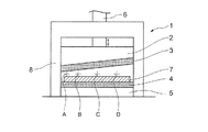
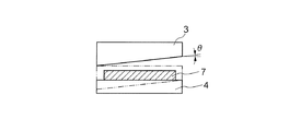
以下添付図面に基づいて本発明の一実施形態における剪断装置のナイフギャップ測定装置を詳細に説明する。図1は剪断装置の一例であるダウンカットシャーの構造を示す模式図を示し、図2は固定刃としての下刃及び可動刃としての上刃の模式図を示す。図1において、1はダウンカットシャー、2は上刃ホルダ、3は上刃、4は下刃、5は下刃ホルダ、6は上刃ホルダを鉛直方向へ移動させる切断用駆動装置、7は鋼板、8はフレームを示す。 Hereinafter, a knife gap measuring device of a shearing device according to an embodiment of the present invention will be described in detail with reference to the accompanying drawings. FIG. 1 is a schematic diagram showing a structure of a down cut shear which is an example of a shearing device, and FIG. 2 is a schematic diagram of a lower blade as a fixed blade and an upper blade as a movable blade. In FIG. 1, 1 is a down cut shear, 2 is an upper blade holder, 3 is an upper blade, 4 is a lower blade, 5 is a lower blade holder, 6 is a cutting drive device for moving the upper blade holder in the vertical direction, and 7 is A steel plate, 8 indicates a frame.
上刃3は細長い直方体形状に形成される。上刃3には、その下端部の長手方向すなわち刃幅方向に伸びる稜に刃が加工されている。正面からみて上刃3は所定のレーキ角θを有するように傾けられる。上刃3は上刃ホルダ2にボルト等の結合手段によって交換可能に保持される。門型のフレーム8には切断用シリンダ装置、クランク機構等の切断用駆動装置6が取り付けられていて、駆動装置6の下端には上刃ホルダ2が取り付けられる。上刃ホルダ2は門型のフレーム8に鉛直方向に移動可能にガイドされる。上刃ホルダ2に保持される上刃3は、駆動装置6によって鉛直方向に上下させられる。
The
下刃4は細長い直方体形状に形成される。下刃4には、その上端部の長手方向すなわち刃幅方向に伸びる稜に刃が加工されている。下刃4は下刃ホルダ5にボルト等の結合手段によって交換可能に保持される。下刃ホルダ5はフレーム8に固定されている。
The
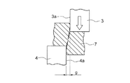
下刃4の上方には、図示しない送り装置によって鋼板7が搬送される。図2に示すように、上方に吊り下げた上刃3を降下させると、上刃3と下刃4との間に鋼板7が挟まれる。さらに上刃3を下降させると、図3に示すように鋼板7の剪断が開始する。
A
図3における上刃3と下刃4との左右方向の隙間がナイフギャップgであり、剪断性能に大きく影響する。ナイフギャップgは、互いに平行な下刃4の内側面4aと上刃3の内側面3aとの間の隙間である。ナイフギャップgが過大だったり、小さ過ぎたりする場合には、鋼板7の剪断面にたれ、かえり、機械割れ等の形状不良が発生する。このためナイフギャップgは最適値になるように調節されている。そのためには、ナイフギャップgの正確な測定が欠かせない。
A gap in the left-right direction between the
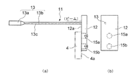
ナイフギャップgを正確に測定するために、測定冶具として下刃端面ゼロ点リセット冶具11(以下、単に冶具11という)を用意する。この冶具11は、下刃4の内側面4aに取り付けられ、下刃4の内側面4aの位置を測定するのに使用される。図4に示すように、冶具11は、正面図が長方形状に形成される板状の冶具本体12と、冶具本体12に直交する方向に伸びる柄13を備える。冶具本体12には、下刃4の内側面4aに接触可能な平らな基準面12aが形成される。下刃4の内側面4aに冶具本体12を取り付けた状態で、冶具本体12の基準面12aの一部が下刃4から露出する。冶具本体12には、冶具本体12を下刃4に着脱可能に取り付けるための一対のリング形状の磁石15a,15bが埋め込まれる。柄13は、冶具本体12に接続される小径部13bと、作業員が把持する大径部13aと、を有する。柄13の小径部13bには、長手方向に伸びるスリット13cが形成される。このスリット13cは後述するセンサ18を冶具本体12の基準面12aと直交する方向に配置するのに利用される。
In order to accurately measure the knife gap g, a lower blade end face zero point reset jig 11 (hereinafter simply referred to as a jig 11) is prepared as a measurement jig. The
下刃4に冶具を取り付ける際、上刃3は下刃4から離間させられている。作業員は冶具11の柄13をつかみ、冶具本体12を下刃4の内側面4aに吸着させる。下刃4の内側面4aと冶具本体12の基準面12aとが接触するので、下刃4の内側面4aの位置は冶具本体12の基準面12aに転写される。冶具本体12の基準面12aの一部は下刃4から露出しており、基準面12aは垂直上方向に延長されている。後述するセンサ18によって冶具本体12の基準面12aの水平方向の位置を測定することによって、下刃4の内側面4aの水平方向の位置を測定することが可能になる。
When attaching a jig to the
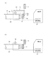
図5は、ナイフギャップgを測定する測定方法の工程図の一例を示す。この図5には、剪断装置として鋼板の幅方向の両端部を切断するサイドシャーのナイフギャップを測定する例が示されている。サイドシャーは、ナイフギャップ測定作業がその設備特性から非常に危険度が高く、本発明の測定方法を適用する意義が大きい。 FIG. 5 shows an example of a process diagram of a measuring method for measuring the knife gap g. FIG. 5 shows an example of measuring a knife gap of a side shear that cuts both ends in the width direction of a steel plate as a shearing device. The side shear is very dangerous because the knife gap measurement operation is very dangerous due to its equipment characteristics, and the measurement method of the present invention is significant.
まず、図5(a)に示すように、上刃3を上昇限の位置まで上昇させる。そして、板状の測定用鋼板19を送り装置としてのテーブルローラ20の上に載せ、搬送する。測定用鋼板19は、その幅方向の端面が下刃4に接触しないように図示しないピンチローラに挟まれている。この測定用鋼板19はセンサを取り付けるのに使用されるが、ナイフギャップ測定時のライン内立入り用の足場も兼ねている。測定用鋼板19を使用することによって、テーブルローラ20間に開口部がなくなり、測定用鋼板19上から容易に測定作業ができるようになる。
First, as shown to Fig.5 (a), the
次に、下刃4の内側面4aの所定の位置に冶具11を取り付ける。作業員は冶具11の柄13を掴んで冶具本体12を下刃4の内側面4aに冶具本体12を吸着させる。そして、測定用鋼板19の上にセンサーベース(図示せず)を固定する。ここで、冶具11の基準面12aに直交する方向にセンサ18を配置できるように、センサベースの長手方向と冶具11の柄13の長手方向が一致するようにセンサベースが位置決めされる。
Next, the
次に、センサベース上にセンサ18をセットする。センサ18には、セットの容易さから市販の非接触の光学式のセンサ(例えばキーエンス社製のIL-100)が用いられる。光学式のセンサの他に機械式のストロークセンサも使用することもできる。センサ18は、例えば市販品のマグネットスタンドを介してセンサベースに取り付けられる。
Next, the
センサ18は、下刃4の長手方向に複数配置される(図1のA〜D点参照)。例えば、刃替え測定時は3点(A,B,C)にセンサ18がセットされ、保全時には4点(A,B,C,D)にセンサ18がセットされる。
A plurality of
なお、センサ18の測定方向が、冶具11の基準面12aに対して完全に垂直になっていることが理想であるが、概ねの目分量で垂直になっていれば、精度上問題はない。センサ18の測定方向の目分量による角度誤差をΔθとすると、ナイフギャップgの測定値への影響は、単純な幾何学により、1−cos(Δθ)で与えられるからである。仮にΔθが5°の場合でもナイフギャップgへの影響は0.4%以下と微小である。
Although it is ideal that the measurement direction of the
次に、センサ18から冶具11の基準面12aまでの距離を測定する。センサ18のアンプ21は運転室等の遠隔操作室に配置される。アンプ21にはセンサ18の出力信号である距離が表示される。センサ18によって距離を測定後、センサ18のアンプ21にリセット機能がある場合は、リセットしてアンプ21の表示をゼロにする。リセット機能がない場合は、アンプ21に表示されている値を記録する。
Next, the distance from the
次に、図5(b)に示すように、冶具11を下刃4から取り外し、センサ18の測定可能な高さまで、上刃3を下降させる。そして、センサ18から上刃3の内側面3aまでの距離を測定する。アンプ21に表示されたセンサ18の出力信号の値がナイフギャップgを示しており、これを記録すれば、測定作業は完了する。センサ18にリセット機能がない場合も、アンプ21に表示されている値から、先に測定した、冶具11の基準面12aまでの距離の測定値を差し引くだけで、ナイフギャップgの値を得ることができる。
Next, as shown in FIG. 5B, the
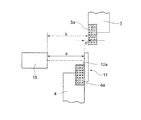
図6は、センサ18の出力信号である距離とナイフギャップgとの関係を示す模式図である。センサ18から下刃4の内側面4aまでの水平方向の距離は、冶具11の基準面12aまでの水平方向の測定「a」で表される。センサ18がリセット可能な場合には、距離「a」=0となる。
FIG. 6 is a schematic diagram showing the relationship between the distance that is the output signal of the
次に、センサ18を動かさずに、冶具11を取り外し、上刃3をセンサ18の測定可能な位置まで下降させる。この時のセンサ18の出力は、上刃3の内側面3aまでの距離「b」となる。ナイフギャップgは「b」−「a」で与えられるが、「a」をリセットしてゼロにしている場合は、「b’」が測定結果となる。このように、冶具11を使用することにより、一つのセンサ18でナイフギャップgを精度よく測定することができる。
Next, the
さらなる自動化を進めるために、センサ18のアンプ21にプログラマブルコントローラ等のコンピュータを電気的に接続し、図示しないコンピュータでナイフギャップgが適正範囲にあるか否かの良否判定を行ってもよい。この場合、コンピュータには、予めナイフギャップの適正値が入力される。コンピュータはセンサ18のアンプ21からナイフギャップgの信号を受け、ナイフギャップgが所定の適正範囲にあるかどうかを判定する。良否の判断の結果は、コンピュータのタッチパネル等の表示装置に表示されるのが望ましい。コンピュータの表示装置には、上刃3の降下量(上刃3を降下させる油圧シリンダのロッドの突出量やクランク軸の回転角度等で代替えしてもよい)も表示するのが望ましい。表示装置に上刃3の降下量を表示すれば、上刃3をセンサ18で測定可能な位置まで降下させるのが容易になる。測定したナイフギャップgは、測定ポイント(A〜D)、日付等と共にコンピュータの記憶装置に記憶されることが望ましい。
In order to advance further automation, a computer such as a programmable controller may be electrically connected to the
なお、本発明は上記実施形態に具現化されるのに限られることはなく、本発明の要旨を変更しない範囲で様々に変更可能である。 The present invention is not limited to being embodied in the above-described embodiment, and can be variously modified without changing the gist of the present invention.
本発明は、ダウンカットシャーだけでなく、アップカットシャー、ドラムシャー、トリマ、サイドシャー、スリッター、分割シャー、フライングシャー、エンドシャー、オフライン装置の剪断機等、種々の剪断装置に適用可能である。また、大型だけではなく、小型のものにも適用可能である。 The present invention can be applied not only to a down-cut shear but also to various shearing devices such as an up-cut shear, a drum shear, a trimmer, a side shear, a slitter, a split shear, a flying shear, an end shear, and an offline shear machine. . Moreover, it is applicable not only to a large size but also to a small size.
冶具は固定刃の替わりに可動刃に取り付けられてもよい。また、一つのセンサでナイフギャップを測定する替わりに、固定刃及び可動刃それぞれに対応して二つのセンサを設け、二つのセンサの出力信号からナイフギャップを算出してもよい。 The jig may be attached to the movable blade instead of the fixed blade. Further, instead of measuring the knife gap with one sensor, two sensors may be provided corresponding to each of the fixed blade and the movable blade, and the knife gap may be calculated from the output signals of the two sensors.
3…上刃(可動刃)
3a…上刃の内側面
4…下刃(固定刃)
4a…下刃の内側面
11…下刃端面ゼロ点リセット冶具(測定冶具)
12…冶具本体
12a…基準面
13…柄
15a,15b…磁石
18…センサ
g…ナイフギャップ
3 ... Upper blade (movable blade)
3a ... Inner side surface of
4a ... Inner side surface of
12 ...
Claims (9)
前記固定刃又は前記可動刃の内側面に接触可能な基準面を持つ測定冶具を用意する工程と、
前記固定刃又は前記可動刃から前記測定冶具の基準面の一部が露出するように、前記固定刃又は前記可動刃の内側面に前記測定冶具を着脱可能に取り付ける冶具取付け工程と、
前記測定冶具の基準面の一部と直交する方向に配置されたセンサによって、前記測定冶具の基準面の一部までの距離を測定する基準面測定工程と、を備え、
前記センサが測定した前記測定冶具の基準面の一部までの距離に基づいて、ナイフギャップを算出する剪断装置のナイフギャップ測定方法。 A knife gap measuring method for measuring a knife gap between an inner surface of a fixed blade and an inner surface of a movable blade in a shearing device that shears a workpiece by moving the movable blade toward the fixed blade,
Preparing a measurement jig having a reference surface that can contact the inner surface of the fixed blade or the movable blade;
A jig attachment step for detachably attaching the measurement jig to the inner surface of the fixed blade or the movable blade such that a part of the reference surface of the measurement jig is exposed from the fixed blade or the movable blade;
A reference plane measuring step of measuring a distance to a part of the reference plane of the measurement jig by a sensor arranged in a direction orthogonal to a part of the reference plane of the measurement jig,
A knife gap measuring method of a shearing device that calculates a knife gap based on a distance to a part of a reference plane of the measuring jig measured by the sensor.
前記ナイフギャップ測定方法はさらに、
前記固定刃から前記測定冶具を取り外す工程と、
前記センサが前記可動刃の内側面までの距離を測定できる位置まで、前記可動刃を前記固定刃に向かって移動させる工程と、
前記センサが前記可動刃の内側面までの距離を測定する可動刃測定工程と、を備え、
前記センサが測定した前記測定冶具の基準面の一部までの距離と前記可動刃の内側面までの距離との差に基づいて、ナイフギャップを算出する請求項1に記載の剪断装置のナイフギャップ測定方法。 In the jig attachment step, the measurement jig is detachably attached to the fixed blade,
The knife gap measuring method further includes
Removing the measuring jig from the fixed blade;
Moving the movable blade toward the fixed blade to a position where the sensor can measure the distance to the inner surface of the movable blade;
A movable blade measuring step in which the sensor measures the distance to the inner surface of the movable blade, and
The knife gap of the shearing device according to claim 1, wherein the knife gap is calculated based on a difference between a distance to a part of a reference surface of the measurement jig measured by the sensor and a distance to an inner surface of the movable blade. Measuring method.
前記可動刃測定工程において、前記センサは、前記可動刃の内側面までの距離を測定した後、前記測定冶具の基準面の一部から前記可動刃の内側面までの距離を表示することを特徴とする請求項2に記載の剪断装置のナイフギャップ測定方法。 In the reference plane measurement step, after the sensor measures the distance to a part of the reference plane of the measurement jig, the display of the sensor is reset to zero,
In the movable blade measuring step, the sensor displays the distance from a part of the reference surface of the measurement jig to the inner surface of the movable blade after measuring the distance to the inner surface of the movable blade. A method for measuring a knife gap of a shearing device according to claim 2.
前記固定刃又は前記可動刃の内側面に接触可能な基準面が形成される冶具本体、
前記冶具本体を前記固定刃又は前記可動刃に着脱可能に取り付けるための磁石、
及び前記冶具本体の基準面から直交する方向に伸びる柄を含むことを特徴とする請求項1ないし3のいずれかに記載の剪断装置のナイフギャップ測定方法。 The measuring jig is
A jig body on which a reference surface that can contact the inner surface of the fixed blade or the movable blade is formed;
A magnet for detachably attaching the jig body to the fixed blade or the movable blade;
The knife gap measuring method for a shearing device according to any one of claims 1 to 3, further comprising a handle extending in a direction orthogonal to a reference plane of the jig body.
前記固定刃又は前記可動刃の内側面に接触可能な基準面を有すると共に、この基準面の一部が露出するように前記固定刃又は前記可動刃の内側面に着脱可能に取り付けられる測定冶具と、
前記測定冶具の基準面の一部と直交する方向に配置され、前記測定冶具の基準面の一部までの距離を測定するセンサと、を備え、
前記センサが測定した前記測定冶具の基準面の一部までの距離に基づいて、ナイフギャップを算出する剪断装置のナイフギャップ測定装置。 A knife gap measuring device for measuring a knife gap between an inner surface of a fixed blade and an inner surface of a movable blade in a shearing device that shears a workpiece by moving the movable blade toward the fixed blade,
A measuring jig having a reference surface that can contact the inner surface of the fixed blade or the movable blade, and detachably attached to the inner surface of the fixed blade or the movable blade so that a part of the reference surface is exposed. ,
A sensor that is arranged in a direction orthogonal to a part of the reference plane of the measurement jig, and that measures a distance to a part of the reference plane of the measurement jig,
A knife gap measuring device of a shearing device that calculates a knife gap based on a distance to a part of a reference plane of the measuring jig measured by the sensor.
前記センサは、前記固定刃から前記測定冶具を取り外した後、前記固定刃に向かって移動させた前記可動刃の内側面までの距離を測定し、
前記センサが測定した前記測定冶具の基準面の一部までの距離と前記可動刃の内側面までの距離との差に基づいて、ナイフギャップを算出する請求項5に記載の剪断装置のナイフギャップ測定装置。 The measurement jig is detachably attached to the fixed blade,
The sensor measures the distance to the inner surface of the movable blade moved toward the fixed blade after removing the measurement jig from the fixed blade,
The knife gap of the shearing device according to claim 5, wherein the knife gap is calculated based on a difference between a distance to a part of a reference surface of the measurement jig measured by the sensor and a distance to an inner surface of the movable blade. measuring device.
前記センサは、前記可動刃の内側面までの距離を測定した後、前記測定冶具の基準面の一部から前記可動刃の内側面までの距離を表示することを特徴とする請求項6に記載の剪断装置のナイフギャップ測定装置。 The sensor is reset so that the display of the sensor becomes zero after measuring the distance to a part of the reference plane of the measuring jig,
The said sensor displays the distance from a part of reference surface of the said measurement jig to the inner surface of the said movable blade, after measuring the distance to the inner surface of the said movable blade. Knife gap measuring device of the shearing device.
前記固定刃に向かって移動する前記可動刃の移動量を表示すると共に、
算出されたナイフギャップが適正範囲にあるか否かを判定する制御装置を備えることを特徴とする請求項6又は7に記載の剪断装置のナイフギャップ測定装置。 The knife gap measuring device further includes
While displaying the amount of movement of the movable blade that moves toward the fixed blade,
The apparatus for measuring a knife gap of a shearing device according to claim 6 or 7, further comprising a control device that determines whether or not the calculated knife gap is within an appropriate range.
前記固定刃又は前記可動刃の内側面に接触可能な基準面が形成される冶具本体、
前記冶具本体を前記固定刃又は前記可動刃に着脱可能に取り付けるための磁石、
及び前記冶具本体の基準面から直交する方向に伸びる柄を含むことを特徴とする請求項5ないし8のいずれかに記載の剪断装置のナイフギャップ測定装置。 The measuring jig is
A jig body on which a reference surface that can contact the inner surface of the fixed blade or the movable blade is formed;
A magnet for detachably attaching the jig body to the fixed blade or the movable blade;
The knife gap measuring device for a shearing device according to any one of claims 5 to 8, further comprising a handle extending in a direction orthogonal to a reference plane of the jig body.
Priority Applications (1)
| Application Number | Priority Date | Filing Date | Title |
|---|---|---|---|
| JP2011006874A JP2012148355A (en) | 2011-01-17 | 2011-01-17 | Method and apparatus for measuring knife gap of shearing machine |
Applications Claiming Priority (1)
| Application Number | Priority Date | Filing Date | Title |
|---|---|---|---|
| JP2011006874A JP2012148355A (en) | 2011-01-17 | 2011-01-17 | Method and apparatus for measuring knife gap of shearing machine |
Publications (1)
| Publication Number | Publication Date |
|---|---|
| JP2012148355A true JP2012148355A (en) | 2012-08-09 |
Family
ID=46791146
Family Applications (1)
| Application Number | Title | Priority Date | Filing Date |
|---|---|---|---|
| JP2011006874A Pending JP2012148355A (en) | 2011-01-17 | 2011-01-17 | Method and apparatus for measuring knife gap of shearing machine |
Country Status (1)
| Country | Link |
|---|---|
| JP (1) | JP2012148355A (en) |
Cited By (5)
| Publication number | Priority date | Publication date | Assignee | Title |
|---|---|---|---|---|
| CN105408043A (en) * | 2013-06-03 | 2016-03-16 | 首要金属科技有限责任公司 | Shear |
| CN108247125A (en) * | 2018-02-06 | 2018-07-06 | 江苏江海机床集团有限公司 | A kind of vertical type plate shearing machine |
| JP2019155408A (en) * | 2018-03-12 | 2019-09-19 | ダイハツ工業株式会社 | Press device |
| CN117655391A (en) * | 2023-12-26 | 2024-03-08 | 中国原子能科学研究院 | Shearing device for spent fuel assemblies |
| CN119426699A (en) * | 2025-01-09 | 2025-02-14 | 格拉默车辆部件(常州)有限公司 | Automobile interior metal parts shearing equipment |
-
2011
- 2011-01-17 JP JP2011006874A patent/JP2012148355A/en active Pending
Cited By (6)
| Publication number | Priority date | Publication date | Assignee | Title |
|---|---|---|---|---|
| CN105408043A (en) * | 2013-06-03 | 2016-03-16 | 首要金属科技有限责任公司 | Shear |
| CN108247125A (en) * | 2018-02-06 | 2018-07-06 | 江苏江海机床集团有限公司 | A kind of vertical type plate shearing machine |
| JP2019155408A (en) * | 2018-03-12 | 2019-09-19 | ダイハツ工業株式会社 | Press device |
| JP7042119B2 (en) | 2018-03-12 | 2022-03-25 | ダイハツ工業株式会社 | Press equipment |
| CN117655391A (en) * | 2023-12-26 | 2024-03-08 | 中国原子能科学研究院 | Shearing device for spent fuel assemblies |
| CN119426699A (en) * | 2025-01-09 | 2025-02-14 | 格拉默车辆部件(常州)有限公司 | Automobile interior metal parts shearing equipment |
Similar Documents
| Publication | Publication Date | Title |
|---|---|---|
| US9864362B2 (en) | Method for setting and/or monitoring operating parameters of a workpiece processing machine | |
| JP2012148355A (en) | Method and apparatus for measuring knife gap of shearing machine | |
| CN102441569A (en) | New Control Method of Flying Shear for Rod and Wire Based on T400 | |
| CN105408043A (en) | Shear | |
| US11433498B2 (en) | Method for monitoring a milling method | |
| CN104236465A (en) | Machine for detecting tightening degree and center height of screw | |
| CN105170712A (en) | Automatic leveling and distance-measuring plate shearer set and control method thereof | |
| CN114942200A (en) | Method for analyzing sharpness of straight-edged tool for ultrasonic machining of honeycomb material | |
| CN204295504U (en) | A kind of crystal bar size detecting device cutting all-in-one for silicon single crystal rod | |
| JP2010234522A (en) | Method and apparatus for adjusting lap amount of shear cut type slitter using round blade | |
| JPH0647620A (en) | Gear processing method | |
| CN105444676A (en) | Measuring probe multi-directional positioning device applicable to online scanning | |
| CN104132607A (en) | Welding deformation detection platform for agricultural machinery chassis frame | |
| KR101487397B1 (en) | Curved steel plate cutting system | |
| CN202432959U (en) | Multifunctional disc scissor blade detection rack | |
| CN115041849A (en) | Anti-deformation assembly fixture for butt joint of welding test plates | |
| CN109877650A (en) | A kind of sheared blank cutter life prediction technique | |
| JP4799949B2 (en) | Method and apparatus for adjusting lap amount of shear cut type slitter using round blade | |
| CN111380454B (en) | Safe and intelligent welding machine precision detection method | |
| CN210774182U (en) | Three-axis moving mechanism for online detection of strip steel | |
| CN210513077U (en) | A non-metallic plate thickness gauge error detection and calibration device | |
| CN105526850B (en) | The horizontal drift hammer coaxality measuring mechanism of multi-ram forging hydraulic press and measuring method | |
| CN210499501U (en) | Accurate equipment of tailorring fast based on vision | |
| CN106853543A (en) | A kind of plate shearing machine and its method of testing | |
| CN104400559A (en) | Knife testing system of digital perforating machine tool |