JP2012149604A - Holding sealing material, exhaust emission control apparatus, and method of manufacturing exhaust emission control apparatus - Google Patents
Holding sealing material, exhaust emission control apparatus, and method of manufacturing exhaust emission control apparatus Download PDFInfo
- Publication number
- JP2012149604A JP2012149604A JP2011010166A JP2011010166A JP2012149604A JP 2012149604 A JP2012149604 A JP 2012149604A JP 2011010166 A JP2011010166 A JP 2011010166A JP 2011010166 A JP2011010166 A JP 2011010166A JP 2012149604 A JP2012149604 A JP 2012149604A
- Authority
- JP
- Japan
- Prior art keywords
- sealing material
- holding sealing
- exhaust gas
- casing
- holding
- Prior art date
- Legal status (The legal status is an assumption and is not a legal conclusion. Google has not performed a legal analysis and makes no representation as to the accuracy of the status listed.)
- Pending
Links
Images





Classifications
-
- F—MECHANICAL ENGINEERING; LIGHTING; HEATING; WEAPONS; BLASTING
- F01—MACHINES OR ENGINES IN GENERAL; ENGINE PLANTS IN GENERAL; STEAM ENGINES
- F01N—GAS-FLOW SILENCERS OR EXHAUST APPARATUS FOR MACHINES OR ENGINES IN GENERAL; GAS-FLOW SILENCERS OR EXHAUST APPARATUS FOR INTERNAL-COMBUSTION ENGINES
- F01N3/00—Exhaust or silencing apparatus having means for purifying, rendering innocuous, or otherwise treating exhaust
- F01N3/02—Exhaust or silencing apparatus having means for purifying, rendering innocuous, or otherwise treating exhaust for cooling, or for removing solid constituents of, exhaust
- F01N3/021—Exhaust or silencing apparatus having means for purifying, rendering innocuous, or otherwise treating exhaust for cooling, or for removing solid constituents of, exhaust by means of filters
- F01N3/0211—Arrangements for mounting filtering elements in housing, e.g. with means for compensating thermal expansion or vibration
-
- F—MECHANICAL ENGINEERING; LIGHTING; HEATING; WEAPONS; BLASTING
- F01—MACHINES OR ENGINES IN GENERAL; ENGINE PLANTS IN GENERAL; STEAM ENGINES
- F01N—GAS-FLOW SILENCERS OR EXHAUST APPARATUS FOR MACHINES OR ENGINES IN GENERAL; GAS-FLOW SILENCERS OR EXHAUST APPARATUS FOR INTERNAL-COMBUSTION ENGINES
- F01N13/00—Exhaust or silencing apparatus characterised by constructional features
- F01N13/008—Mounting or arrangement of exhaust sensors in or on exhaust apparatus
-
- F—MECHANICAL ENGINEERING; LIGHTING; HEATING; WEAPONS; BLASTING
- F01—MACHINES OR ENGINES IN GENERAL; ENGINE PLANTS IN GENERAL; STEAM ENGINES
- F01N—GAS-FLOW SILENCERS OR EXHAUST APPARATUS FOR MACHINES OR ENGINES IN GENERAL; GAS-FLOW SILENCERS OR EXHAUST APPARATUS FOR INTERNAL-COMBUSTION ENGINES
- F01N3/00—Exhaust or silencing apparatus having means for purifying, rendering innocuous, or otherwise treating exhaust
- F01N3/08—Exhaust or silencing apparatus having means for purifying, rendering innocuous, or otherwise treating exhaust for rendering innocuous
- F01N3/10—Exhaust or silencing apparatus having means for purifying, rendering innocuous, or otherwise treating exhaust for rendering innocuous by thermal or catalytic conversion of noxious components of exhaust
- F01N3/24—Exhaust or silencing apparatus having means for purifying, rendering innocuous, or otherwise treating exhaust for rendering innocuous by thermal or catalytic conversion of noxious components of exhaust characterised by constructional aspects of converting apparatus
- F01N3/28—Construction of catalytic reactors
- F01N3/2839—Arrangements for mounting catalyst support in housing, e.g. with means for compensating thermal expansion or vibration
- F01N3/2853—Arrangements for mounting catalyst support in housing, e.g. with means for compensating thermal expansion or vibration using mats or gaskets between catalyst body and housing
-
- Y—GENERAL TAGGING OF NEW TECHNOLOGICAL DEVELOPMENTS; GENERAL TAGGING OF CROSS-SECTIONAL TECHNOLOGIES SPANNING OVER SEVERAL SECTIONS OF THE IPC; TECHNICAL SUBJECTS COVERED BY FORMER USPC CROSS-REFERENCE ART COLLECTIONS [XRACs] AND DIGESTS
- Y02—TECHNOLOGIES OR APPLICATIONS FOR MITIGATION OR ADAPTATION AGAINST CLIMATE CHANGE
- Y02T—CLIMATE CHANGE MITIGATION TECHNOLOGIES RELATED TO TRANSPORTATION
- Y02T10/00—Road transport of goods or passengers
- Y02T10/10—Internal combustion engine [ICE] based vehicles
- Y02T10/12—Improving ICE efficiencies
-
- Y—GENERAL TAGGING OF NEW TECHNOLOGICAL DEVELOPMENTS; GENERAL TAGGING OF CROSS-SECTIONAL TECHNOLOGIES SPANNING OVER SEVERAL SECTIONS OF THE IPC; TECHNICAL SUBJECTS COVERED BY FORMER USPC CROSS-REFERENCE ART COLLECTIONS [XRACs] AND DIGESTS
- Y10—TECHNICAL SUBJECTS COVERED BY FORMER USPC
- Y10T—TECHNICAL SUBJECTS COVERED BY FORMER US CLASSIFICATION
- Y10T29/00—Metal working
- Y10T29/49—Method of mechanical manufacture
- Y10T29/49826—Assembling or joining
Landscapes
- Engineering & Computer Science (AREA)
- Chemical & Material Sciences (AREA)
- Chemical Kinetics & Catalysis (AREA)
- Combustion & Propulsion (AREA)
- Mechanical Engineering (AREA)
- General Engineering & Computer Science (AREA)
- Health & Medical Sciences (AREA)
- Toxicology (AREA)
- Analytical Chemistry (AREA)
- Exhaust Gas After Treatment (AREA)
- Exhaust Gas Treatment By Means Of Catalyst (AREA)
Abstract
Description
本発明は、保持シール材、排ガス浄化装置、及び、排ガス浄化装置の製造方法に関する。 The present invention relates to a holding sealing material, an exhaust gas purification device, and a method for manufacturing an exhaust gas purification device.
従来、エンジン等の内燃機関から排出された排ガス中に含まれる有害ガス等の有害物質を浄化するため、内燃機関の排気通路(排ガスが流通する排気管等)には、排ガス浄化装置が設けられている。
排ガス浄化装置は、内燃機関の排気通路にケーシングを設け、ケーシングの中に排ガス処理体を配置した構造となっている。排ガス処理体の一例としては、触媒担体又はディーゼルパティキュレートフィルタ(DPF)が挙げられる。
排ガス処理体に触媒が担持された排ガス浄化装置による有害物質の浄化効率を高めるためには、内燃機関の排気通路及び排ガスの温度を触媒活性化に適した温度(以下、触媒活性化温度ともいう)に維持する必要がある。
Conventionally, in order to purify harmful substances such as harmful gases contained in exhaust gas discharged from an internal combustion engine such as an engine, an exhaust gas purification device has been provided in the exhaust passage (exhaust pipe through which the exhaust gas flows) of the internal combustion engine. ing.
The exhaust gas purification apparatus has a structure in which a casing is provided in an exhaust passage of an internal combustion engine, and an exhaust gas treatment body is disposed in the casing. Examples of the exhaust gas treating body include a catalyst carrier or a diesel particulate filter (DPF).
In order to improve the purification efficiency of harmful substances by the exhaust gas purification device in which the catalyst is supported on the exhaust gas treatment body, the exhaust passage of the internal combustion engine and the temperature of the exhaust gas are temperatures suitable for catalyst activation (hereinafter also referred to as catalyst activation temperature). ) Must be maintained.
上述した通り、排ガス処理体に触媒が担持された排ガス浄化装置は、所定の触媒活性化温度に達するまで昇温した状態でないと、充分な触媒作用を奏することができない。従って、エンジン始動直後の排ガス浄化装置では、排ガス浄化性能が充分なレベルに達するまでにある程度の時間がかかるという問題がある。 As described above, an exhaust gas purifying apparatus in which a catalyst is supported on an exhaust gas treating body cannot exhibit a sufficient catalytic action unless the temperature is raised until a predetermined catalyst activation temperature is reached. Therefore, the exhaust gas purification apparatus immediately after engine startup has a problem that it takes a certain amount of time for the exhaust gas purification performance to reach a sufficient level.
このような問題に対して、エンジン始動直後に排出される有害物質を低減させることを目的として、触媒を急速に加熱する電気加熱触媒コンバータ(EHC;Electrically Heated Catalyst)が提案されている。 In response to such problems, an electrically heated catalytic converter (EHC) that rapidly heats the catalyst has been proposed for the purpose of reducing harmful substances discharged immediately after the engine is started.
例えば、特許文献1には、金属製排ガス処理体を金属製シェル(ケーシング)内に備え、金属製触媒担体(排ガス処理体)に接続した正負の電極部材を金属製シェル壁を絶縁状態に貫通して突出させた構造を有する触媒コンバータ(排ガス浄化装置)が開示されている。
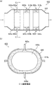
図20(a)は、特許文献1に記載の従来の排ガス浄化装置を模式的に示す断面図である。図20(b)は、図20(a)に示す従来の排ガス浄化装置のC−C線断面図である。
図20(a)及び図20(b)に示す従来の触媒コンバータ(排ガス浄化装置)600には、金属製シェル(ケーシング)620内に金属製触媒担体(排ガス処理体)630a、630b及び630cが配置されている。そして、金属製触媒担体630a、630b及び630cの外表面には、他端部が金属製シェル620を貫通している+側電極部材650a、650b及び650c、並びに、−側電極部材650d、650e及び650fがそれぞれ接続されている。
また、図20(a)及び図20(b)に示す従来の触媒コンバータ600においては、金属製触媒担体630a、630b及び630cの外周面と金属製シェル620の内周面との間に、環状のマット部材(保持シール材)610a、610b及び610cがそれぞれ配置されている。
For example, in Patent Document 1, a metal exhaust gas treatment body is provided in a metal shell (casing), and positive and negative electrode members connected to a metal catalyst carrier (exhaust gas treatment body) are passed through the metal shell wall in an insulated state. A catalytic converter (exhaust gas purification device) having a projecting structure is disclosed.
FIG. 20A is a cross-sectional view schematically showing a conventional exhaust gas purifying apparatus described in Patent Document 1. FIG. FIG.20 (b) is CC sectional view taken on the line of the conventional exhaust gas purification apparatus shown to Fig.20 (a).
20 (a) and 20 (b), a conventional catalytic converter (exhaust gas purification device) 600 includes metal catalyst carriers (exhaust gas treatment bodies) 630a, 630b, and 630c in a metal shell (casing) 620. Has been placed. Further, on the outer surfaces of the
Also, in the conventional
排ガス浄化装置の一種である電気加熱触媒コンバータでは、電極部材が、ケーシングを貫通し、保持シール材を通過して排ガス処理体と接続されており、また、排ガス処理体の温度を測定するためのセンサーが、ケーシングを貫通し、保持シール材を通過して排ガス処理体と接続されることもある。 In an electrically heated catalytic converter, which is a type of exhaust gas purification device, the electrode member passes through the casing, passes through the holding seal material, is connected to the exhaust gas treatment body, and is used for measuring the temperature of the exhaust gas treatment body. The sensor may pass through the casing, pass through the holding sealing material, and be connected to the exhaust gas treating body.
特許文献1には、金属製触媒担体に接続した正負の電極部材を金属製シェル壁を絶縁状態に貫通して突出させた構造を有する触媒コンバータが開示されているものの、上記構造を有する排ガス浄化装置をどのように製造するかについては何ら開示されていない。そのため、このような構造を有する排ガス浄化装置を製造する際に、電極部材及び/又はセンサー(以下、電極部材及び/又はセンサーを電極部材等とも記載する)を排ガス浄化装置にどのように配置すればよいかについては知られていない。 Patent Document 1 discloses a catalytic converter having a structure in which positive and negative electrode members connected to a metal catalyst carrier are protruded through an insulating state through a metal shell wall, but exhaust gas purification having the above structure is disclosed. There is no disclosure on how to manufacture the device. For this reason, when manufacturing an exhaust gas purification apparatus having such a structure, how an electrode member and / or a sensor (hereinafter, the electrode member and / or sensor is also referred to as an electrode member) is arranged in the exhaust gas purification apparatus. I don't know what to do.
また、特許文献1に記載の従来の触媒コンバータでは、金属製シェルが2つの部品からなっている。そのため、特許文献1に記載の従来の触媒コンバータは、クラムシェル方式によって製造されていると考えられる。クラムシェル方式では、保持シール材が巻き付けられた排ガス処理体を第1の部品上に載置した後に第2の部品を被せて密封する。 Moreover, in the conventional catalytic converter described in Patent Document 1, the metal shell is composed of two parts. Therefore, it is considered that the conventional catalytic converter described in Patent Document 1 is manufactured by the clamshell method. In the clamshell method, after the exhaust gas treating body around which the holding sealing material is wound is placed on the first part, the second part is put on and sealed.
クラムシェル方式以外の排ガス浄化装置の製造方法としては、圧入方式(スタッフィング方式)及びサイジング方式(スウェージング方式)が知られている。圧入方式では、保持シール材が巻き付けられた排ガス処理体を、ケーシングの内部に圧入する。サイジング方式では、保持シール材が巻き付けられた排ガス処理体を、ケーシングの内部に挿入した後、ケーシングを縮径する。
特許文献1と同様の構成を有する排ガス浄化装置を、圧入方式又はサイジング方式により製造する場合、電極部材をケーシングの外部から配置する必要がある。しかしながら、電極部材をケーシングの外部から挿入すると、電極部材によって保持シール材が圧壊しやすくなる。
As a method for manufacturing an exhaust gas purification device other than the clamshell method, a press-fitting method (stuffing method) and a sizing method (swaging method) are known. In the press-fitting method, the exhaust gas treating body around which the holding sealing material is wound is press-fitted into the casing. In the sizing method, after the exhaust gas treating body around which the holding sealing material is wound is inserted into the casing, the diameter of the casing is reduced.
When manufacturing the exhaust gas purification apparatus having the same configuration as that of Patent Document 1 by the press-fitting method or the sizing method, it is necessary to dispose the electrode member from the outside of the casing. However, when the electrode member is inserted from the outside of the casing, the holding sealing material is easily crushed by the electrode member.
本発明は、上記課題を解決するためになされたものであり、排ガス浄化装置に使用する際に電極部材及び/又はセンサーを配置しやすい保持シール材、上記保持シール材を用いた排ガス浄化装置、及び、上記排ガス浄化装置の製造方法を提供することを目的とする。 The present invention has been made in order to solve the above problems, and when used in an exhaust gas purification apparatus, a holding sealing material in which an electrode member and / or a sensor can be easily disposed, an exhaust gas purification apparatus using the holding sealing material, And it aims at providing the manufacturing method of the said exhaust gas purification apparatus.
本発明者らは、貫通部が形成されている保持シール材を用いることにより、上記保持シール材の貫通部に電極部材及び/又はセンサーを配置することができることを見出し、本発明を完成した。 The present inventors have found that an electrode member and / or a sensor can be disposed in the penetrating portion of the holding sealing material by using a holding sealing material in which a penetrating portion is formed, and the present invention has been completed.
すなわち、請求項1に記載の保持シール材は、
無機繊維を含み、
マット状であり、
保持シール材の幅方向に平行な第1の端面及び第2の端面を有する保持シール材であって、
保持シール材の厚さ方向に貫通する貫通部が、少なくとも1つ形成されていることを特徴とする。
That is, the holding sealing material according to claim 1 is:
Containing inorganic fibers,
Mat-shaped,
A holding sealing material having a first end surface and a second end surface parallel to the width direction of the holding sealing material,
At least one penetrating portion penetrating in the thickness direction of the holding sealing material is formed.
請求項1に記載の保持シール材には、保持シール材の厚さ方向に貫通する貫通部が、少なくとも1つ形成されている。従って、請求項1に記載の保持シール材を用いて排ガス浄化装置を製造する場合、上記保持シール材の貫通部に電極部材及び/又はセンサーを配置することができる。 The holding sealing material according to claim 1 has at least one penetrating portion penetrating in the thickness direction of the holding sealing material. Therefore, when manufacturing the exhaust gas purifying apparatus using the holding sealing material according to claim 1, an electrode member and / or a sensor can be disposed in the penetrating portion of the holding sealing material.
請求項2に記載の保持シール材では、上記貫通部は、2つ以上形成されている。
請求項2に記載の保持シール材を用いて排ガス浄化装置を製造する場合、保持シール材に複数の貫通部が形成されているため、それぞれの貫通部に電極部材及び/又はセンサーを配置することができる。
In the holding sealing material according to claim 2, two or more of the through portions are formed.
When an exhaust gas purification apparatus is manufactured using the holding sealing material according to claim 2, since a plurality of through portions are formed in the holding sealing material, an electrode member and / or a sensor is disposed in each through portion. Can do.
請求項3に記載の保持シール材では、上記2つ以上の貫通部のうち、1組の貫通部は、保持シール材の幅方向の中心線に対して線対称となる位置、保持シール材の長さ方向の中心線に対して線対称となる位置、又は、保持シール材の中心に対して点対称となる位置に形成されている。
保持シール材に複数の貫通部が形成されていると、貫通部の面積分だけ保持シール材の面積が減少するため、保持シール材の保持力及び引っ張り強度が低下することが考えられる。しかしながら、保持シール材の幅方向の中心線に対して線対称となる位置、保持シール材の長さ方向の中心線に対して線対称となる位置、又は、保持シール材の中心に対して点対称となる位置に1組の貫通部が形成されていると、貫通部が形成される位置が偏りすぎないため、保持シール材の保持力及び引っ張り強度が低下することを防止することができる。また、上記位置に1組の貫通部が形成されていると、貫通部が形成される位置が偏りすぎないため、保持シール材が破損しにくい。
なお、「1組の貫通部」とは、保持シール材に形成された2つ以上の貫通部のうちの2つの貫通部のことをいう。
In the holding sealing material according to claim 3, of the two or more through portions, one set of the through portions has a position that is line-symmetric with respect to the center line in the width direction of the holding sealing material. It is formed at a position that is line-symmetric with respect to the center line in the length direction or a position that is point-symmetric with respect to the center of the holding sealing material.
If a plurality of penetrating portions are formed in the holding sealing material, the area of the holding sealing material is reduced by the area of the penetrating portion, so that the holding force and tensile strength of the holding sealing material may be reduced. However, a position that is line-symmetric with respect to the center line in the width direction of the holding seal material, a position that is line-symmetric with respect to the center line in the length direction of the holding seal material, or a point with respect to the center of the holding seal material If one set of penetrating portions are formed at symmetrical positions, the positions where the penetrating portions are formed are not excessively biased, so that the holding force and the tensile strength of the holding sealing material can be prevented from being lowered. In addition, when one set of penetrating portions is formed at the above position, the position where the penetrating portions are formed is not excessively biased, and the holding sealing material is not easily damaged.
In addition, "one set of penetration part" means two penetration parts among the two or more penetration parts formed in the holding sealing material.
請求項4に記載の保持シール材では、上記1組の貫通部は、保持シール材の幅方向の中心線に対して線対称となる位置に形成されており、上記1組の貫通部間の距離は、保持シール材の長さ方向の長さの50%である。
上記位置に1組の貫通部が形成されていると、保持シール材を排ガス処理体等の被巻付体の周囲に巻きつけた際に、1組の貫通部が正対する。従って、請求項4に記載の保持シール材を用いて電気加熱触媒コンバータを製造する場合、正対する保持シール材の貫通部にそれぞれ電極部材を配置することができる。その結果、正対する2つの電極部材により発生する熱を排ガス処理体に均等に伝えることができるため、効率良く排ガス処理体を加熱することができる。
In the holding sealing material according to claim 4, the one set of penetrating portions are formed at positions that are line-symmetric with respect to the center line in the width direction of the holding sealing material, and between the one set of penetrating portions. The distance is 50% of the length in the length direction of the holding sealing material.
If one set of penetration parts is formed in the above-mentioned position, when the holding sealing material is wound around the wound body such as the exhaust gas treating body, the one set of penetration parts face each other. Therefore, when an electric heating catalytic converter is manufactured using the holding sealing material according to claim 4, the electrode members can be respectively disposed in the through portions of the holding sealing material facing each other. As a result, since the heat generated by the two electrode members facing each other can be evenly transmitted to the exhaust gas treating body, the exhaust gas treating body can be efficiently heated.
請求項5に記載の保持シール材では、上記保持シール材の上記第1の端面及び上記第2の端面には、それぞれ、少なくとも1つの突出部からなる段差が設けられている。
保持シール材の第1の端面及び第2の端面にそれぞれ段差が設けられていると、保持シール材の突出部によって保持シール材が嵌合されやすくなるため、保持シール材の嵌合部から排ガスが漏れにくくなり、排ガスのシール性を保つことができる。また、保持シール材の第1の端面及び第2の端面にそれぞれ段差が設けられていると、保持シール材の突出部によって保持シール材が嵌合されやすくなるため、保持シール材の幅方向に排ガス浄化装置に力が加えられたとしても、排ガス処理体から保持シール材がずれにくくなる。
In the holding sealing material according to claim 5, the first end surface and the second end surface of the holding sealing material are each provided with a step including at least one projecting portion.
If the first end surface and the second end surface of the holding sealing material are stepped, the holding sealing material is easily fitted by the protruding portion of the holding sealing material. Is less likely to leak, and the sealing of exhaust gas can be maintained. In addition, when the first end surface and the second end surface of the holding sealing material are provided with steps, the holding sealing material is easily fitted by the protruding portion of the holding sealing material. Even if force is applied to the exhaust gas purification device, the holding sealing material is less likely to be displaced from the exhaust gas treating body.
請求項6に記載の保持シール材では、上記保持シール材の貫通部は、上記保持シール材の突出部以外の部分に形成されている。
保持シール材の突出部の面積は、保持シール材の突出部以外の部分の面積に対して相対的に小さいため、保持シール材の突出部に貫通部が形成されていると、保持シール材の突出部の面積が小さくなりすぎるため、保持シール材の保持力及び引っ張り強度が低下しやすくなる。これに対して、保持シール材の突出部以外の部分に貫通部が形成されていると、保持シール材の貫通部が形成されていない部分の面積を確保することができるため、保持シール材の引っ張り強度が低下することを防止することができる。また、打ち抜きによって貫通部を形成する場合、保持シール材の突出部に貫通部を形成することに比べて、打ち抜く対象の面積が大きいため、保持シール材の突出部以外の部分に貫通部を形成することが容易となる。
In the holding sealing material according to claim 6, the penetrating portion of the holding sealing material is formed in a portion other than the protruding portion of the holding sealing material.
Since the area of the protruding portion of the holding sealing material is relatively small with respect to the area of the portion other than the protruding portion of the holding sealing material, if the through-hole is formed in the protruding portion of the holding sealing material, Since the area of the protruding portion becomes too small, the holding force and the tensile strength of the holding sealing material are likely to be reduced. On the other hand, since the area of the portion where the penetrating portion of the holding sealing material is not formed can be ensured when the penetrating portion is formed in a portion other than the protruding portion of the holding sealing material, It is possible to prevent a decrease in tensile strength. In addition, when forming a through part by punching, the area to be punched is larger than forming a through part in the projecting part of the holding seal material, so the through part is formed in a part other than the projecting part of the holding seal material. Easy to do.
請求項7に記載の保持シール材では、上記保持シール材の貫通部は、保持シール材の厚さ方向に対して斜めに形成されている。
圧入方式により排ガス浄化装置を製造する場合、保持シール材が巻き付けられた排ガス処理体をケーシングの内部に圧入する際に、圧入方向と反対の方向に、せん断力が加わる。請求項7に記載の保持シール材を用いると、せん断力によって保持シール材の貫通部の向きが変えられる結果、圧入後の貫通部の向きを、保持シール材の長さ方向に対して略垂直とすることができる。従って、電極部材及び/又はセンサーを保持シール材の貫通部に容易に配置することができる。
In the holding sealing material according to claim 7, the through portion of the holding sealing material is formed obliquely with respect to the thickness direction of the holding sealing material.
When an exhaust gas purification device is manufactured by a press-fitting method, a shearing force is applied in a direction opposite to the press-fitting direction when the exhaust gas treating body around which the holding sealing material is wound is press-fitted into the casing. When the holding sealing material according to claim 7 is used, the direction of the penetrating portion of the holding sealing material is changed by the shearing force. As a result, the direction of the penetrating portion after press-fitting is substantially perpendicular to the length direction of the holding sealing material. It can be. Therefore, the electrode member and / or the sensor can be easily disposed in the penetrating portion of the holding sealing material.
請求項8に記載の排ガス浄化装置は、
孔を有するケーシングと、
上記ケーシングに収容された排ガス処理体と、
上記排ガス処理体の周囲に巻き付けられ、上記排ガス処理体及び上記ケーシングの間に配設された保持シール材とを備える排ガス浄化装置であって、
上記保持シール材は、請求項1〜7のいずれかに記載の保持シール材であり、
上記排ガス処理体の周囲に巻き付けられた上記保持シール材の貫通部の位置は、上記ケーシングの孔の位置と一致していることを特徴とする。
The exhaust gas purifying apparatus according to claim 8 comprises:
A casing having a hole;
An exhaust gas treating body housed in the casing;
An exhaust gas purification apparatus comprising a holding sealing material wound around the exhaust gas treatment body and disposed between the exhaust gas treatment body and the casing,
The holding sealing material is the holding sealing material according to any one of claims 1 to 7,
The position of the penetrating portion of the holding sealing material wound around the exhaust gas treating body coincides with the position of the hole of the casing.
請求項8に記載の排ガス浄化装置では、排ガス処理体の周囲に巻き付けられた保持シール材の貫通部の位置が、ケーシングの孔の位置と一致している。従って、ケーシングを貫通して排ガス処理体と接続させる部材を、保持シール材の貫通部及びケーシングの孔に配置することができる。 In the exhaust gas purifying apparatus according to the eighth aspect, the position of the penetrating portion of the holding sealing material wound around the exhaust gas treating body coincides with the position of the hole of the casing. Therefore, a member that penetrates the casing and is connected to the exhaust gas treating body can be disposed in the penetrating portion of the holding sealing material and the hole of the casing.
請求項9に記載の排ガス浄化装置は、上記排ガス処理体と接続し、上記保持シール材を通過し、かつ、上記ケーシングを貫通する電極部材及び/又はセンサーをさらに備え、上記電極部材及び/又はセンサーは、上記保持シール材の貫通部及び上記ケーシングの孔に配置されている。
このように、請求項9に記載の排ガス浄化装置には、保持シール材に形成された貫通部に電極部材及び/又はセンサーを配置することができる。特に、上記保持シール材の貫通部に電極部材を配置した排ガス浄化装置は、電気加熱触媒コンバータとして使用することができる。
The exhaust gas purifying apparatus according to claim 9, further comprising an electrode member and / or a sensor connected to the exhaust gas treating body, passing through the holding sealing material, and penetrating the casing, and the electrode member and / or The sensor is disposed in the penetrating portion of the holding sealing material and the hole of the casing.
As described above, in the exhaust gas purifying apparatus according to the ninth aspect, the electrode member and / or the sensor can be disposed in the penetrating portion formed in the holding sealing material. In particular, an exhaust gas purifying apparatus in which an electrode member is disposed in a through portion of the holding sealing material can be used as an electric heating catalytic converter.
請求項10に記載の排ガス浄化装置は、上記保持シール材が周囲に巻き付けられた上記排ガス処理体を、上記ケーシングに収容する収容工程と、上記排ガス処理体の周囲に巻き付けられた保持シール材の貫通部の位置を、上記ケーシングの孔の位置に合わせる位置調整工程と、上記排ガス処理体に接続し、上記保持シール材を通過し、かつ、上記ケーシングを貫通するように電極部材及び/又はセンサーを配置する配置工程とを含む製造方法により製造され、上記収容工程では、上記保持シール材が周囲に巻き付けられた上記排ガス処理体を、上記ケーシングの内部に圧入するか、又は、上記保持シール材が周囲に巻き付けられた上記排ガス処理体を、上記ケーシングの内部に挿入した後、上記ケーシングを縮径し、上記配置工程では、上記電極部材及び/又はセンサーを、上記保持シール材の貫通部及び上記ケーシングの孔に配置する。
このように、請求項9に記載の排ガス浄化装置は、圧入方式又はサイジング方式により製造することができる。
The exhaust gas purifying apparatus according to claim 10 includes: a housing step of housing the exhaust gas treatment body around which the holding seal material is wound in the casing; and a holding seal material wound around the exhaust gas treatment body. A position adjusting step for adjusting the position of the penetrating portion to the position of the hole of the casing, and the electrode member and / or sensor connected to the exhaust gas treating body, passing through the holding sealing material, and penetrating the casing. In the housing step, the exhaust gas treatment body around which the holding sealing material is wound is press-fitted into the casing, or the holding sealing material is arranged in the housing step. After the exhaust gas treating body wound around is inserted into the casing, the casing is reduced in diameter. The pole pieces and / or sensor, disposed in the penetration portion and the hole of the casing of the holding sealing material.
Thus, the exhaust gas purifying apparatus according to claim 9 can be manufactured by a press-fitting method or a sizing method.
請求項11に記載の排ガス浄化装置の製造方法は、
孔を有するケーシングと、
上記ケーシングに収容された排ガス処理体と、
上記排ガス処理体の周囲に巻き付けられ、上記排ガス処理体及び上記ケーシングの間に配設された保持シール材とを備える排ガス浄化装置の製造方法であって、
上記保持シール材として請求項1〜7のいずれかに記載の保持シール材を用いて、上記排ガス処理体の周囲に巻き付けられた保持シール材の貫通部の位置を、上記ケーシングの孔の位置に合わせる位置調整工程を含むことを特徴とする。
請求項11に記載の排ガス浄化装置の製造方法では、請求項8に記載の排ガス浄化装置を好適に製造することができる。
The method for manufacturing an exhaust gas purifying apparatus according to
A casing having a hole;
An exhaust gas treating body housed in the casing;
A method of manufacturing an exhaust gas purification device comprising a holding sealing material wound around the exhaust gas treatment body and disposed between the exhaust gas treatment body and the casing,
Using the holding sealing material according to any one of claims 1 to 7 as the holding sealing material, the position of the penetrating portion of the holding sealing material wound around the exhaust gas treating body is set to the position of the hole of the casing. It includes a position adjusting step for matching.
In the method for manufacturing the exhaust gas purifying apparatus according to
請求項12に記載の排ガス浄化装置の製造方法は、上記位置調整工程の後の工程として、上記排ガス処理体に接続し、上記保持シール材を通過し、かつ、上記ケーシングを貫通するように電極部材及び/又はセンサーを配置する配置工程をさらに含み、上記配置工程では、上記電極部材及び/又はセンサーを、上記保持シール材の貫通部及び上記ケーシングの孔に配置する。
請求項12に記載の排ガス浄化装置の製造方法では、請求項9に記載の排ガス浄化装置を好適に製造することができる。
The method for manufacturing an exhaust gas purifying device according to
In the exhaust gas purifying apparatus manufacturing method according to the twelfth aspect, the exhaust gas purifying apparatus according to the ninth aspect can be preferably manufactured.
請求項13に記載の排ガス浄化装置の製造方法は、上記位置調整工程の前の工程として、上記保持シール材が周囲に巻き付けられた上記排ガス処理体を、上記ケーシングに収容する収容工程をさらに含み、上記収容工程では、上記保持シール材が周囲に巻き付けられた上記排ガス処理体を、上記ケーシングの内部に圧入するか、又は、上記保持シール材が周囲に巻き付けられた上記排ガス処理体を、上記ケーシングの内部に挿入した後、上記ケーシングを縮径する。
このように、排ガス浄化装置を製造するために、圧入方式又はサイジング方式を用いることができる。
The method for manufacturing an exhaust gas purifying apparatus according to claim 13 further includes a housing step of housing the exhaust gas treating body around which the holding sealing material is wound in the casing as a step before the position adjusting step. In the housing step, the exhaust gas treating body around which the holding sealing material is wound is press-fitted into the casing, or the exhaust gas treating body around which the holding sealing material is wound is After being inserted into the casing, the casing is reduced in diameter.
Thus, in order to manufacture the exhaust gas purification apparatus, a press-fitting method or a sizing method can be used.
以下、本発明の実施形態について具体的に説明する。しかしながら、本発明は、以下の実施形態に限定されるものではなく、本発明の要旨を変更しない範囲において適宜変更して適用することができる。 Hereinafter, embodiments of the present invention will be specifically described. However, the present invention is not limited to the following embodiments, and can be applied with appropriate modifications without departing from the scope of the present invention.
(第一実施形態)
以下、本発明の保持シール材、排ガス浄化装置、及び、排ガス浄化装置の製造方法の一実施形態である第一実施形態について、図面を参照しながら説明する。
(First embodiment)
Hereinafter, a first embodiment, which is an embodiment of a method for manufacturing a holding sealing material, an exhaust gas purification device, and an exhaust gas purification device of the present invention, will be described with reference to the drawings.
まず、本発明の第一実施形態に係る保持シール材について説明する。
図1は、本発明の第一実施形態に係る保持シール材の一例を模式的に示す斜視図である。
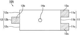
図1に示す保持シール材10Aは、アルミナ−シリカ繊維等の無機繊維からなり、マット状である。より詳細には、保持シール材10Aは、所定の長さ(図1中、矢印L1で示す)、幅(図1中、矢印W1で示す)、及び、厚さ(図1中、矢印T1で示す)を有する平面視略矩形の平板状の形状を有している。また、保持シール材10Aは、保持シール材10Aの幅W1方向に平行な第1の端面11(11a、11b及び11c)、並びに、第2の端面12(12a、12b及び12c)を有している。さらに、保持シール材10Aは、貫通部14aを有している。
本明細書において、「保持シール材の長さ方向の長さ」とは、保持シール材の長さ方向における、第1の端面と第2の端面との距離をいうこととする。また、「保持シール材の長さ方向の長さ」を、単に「保持シール材の長さ」とも記載する。
First, the holding sealing material according to the first embodiment of the present invention will be described.
FIG. 1 is a perspective view schematically showing an example of a holding sealing material according to the first embodiment of the present invention.
The holding
In this specification, “the length in the length direction of the holding sealing material” refers to the distance between the first end surface and the second end surface in the length direction of the holding sealing material. Further, “the length in the length direction of the holding sealing material” is also simply referred to as “the length of the holding sealing material”.
本実施形態の保持シール材では、上記第1の端面及び上記第2の端面には、それぞれ、少なくとも1つの突出部からなる段差が設けられている。
図1に示す保持シール材10Aでは、第1の端面11に2つの突出部13a及び13cが形成されており、第2の端面12に1つの突出部13bが形成されている。なお、保持シール材10Aの第1の端面11と第2の端面12とを当接させた際、突出部13bが形成する凸部と、突出部13a及び13cが形成する凹部とは嵌合される。
このように、図1に示す保持シール材10Aには、第1の端面11及び第2の端面12にそれぞれ3段の段差が設けられている。
図2は、図1に示す保持シール材の平面図である。
図2には、保持シール材10Aに形成されている突出部13a、13b及び13cの具体的な位置を示している。
In the holding sealing material of the present embodiment, the first end surface and the second end surface are each provided with a step including at least one protrusion.
In the holding sealing material 10 </ b> A shown in FIG. 1, two projecting
As described above, the holding sealing material 10 </ b> A shown in FIG. 1 is provided with three steps on the
FIG. 2 is a plan view of the holding sealing material shown in FIG.
FIG. 2 shows specific positions of the
本明細書において、「突出部」とは、以下の領域を指すこととする。
保持シール材の端面(第1の端面又は第2の端面)において、各段差の始点が属する端面と該段差の終点が属する端面との間の領域に存在する保持シール材の部分を「突出部」ということとする。従って、保持シール材の突出部は、保持シール材の第1の端面側及び第2の端面側にそれぞれ存在する。
In the present specification, the “projection” refers to the following region.
On the end face (first end face or second end face) of the holding sealing material, the portion of the holding sealing material existing in the region between the end face to which the start point of each step belongs and the end face to which the end point of the step belongs is referred to as “projection part. " Therefore, the protrusions of the holding sealing material are present on the first end surface side and the second end surface side of the holding sealing material, respectively.
本実施形態の保持シール材では、保持シール材の長さ方向において、突出部の長さは略等しいことが好ましい。つまり、保持シール材のいずれの部分においても、第1の端面と第2の端面との距離が略等しいことが好ましい。
図1に示す保持シール材10Aでは、保持シール材10Aの長さL1方向において、突出部13aの長さ(図1中、矢印X1で示す)、突出部13bの長さ(図1中、矢印X2で示す)、及び、突出部13cの長さ(図1中、矢印X3で示す)がいずれも略等しくなっている。従って、図1に示す保持シール材10Aは、一定の長さL1を有している。
なお、「略等しい」とは、完全に同じ長さでないことを許容するものであり、実質的に同じ長さと同視し得る場合を含む。
In the holding sealing material of this embodiment, it is preferable that the lengths of the protrusions are substantially equal in the length direction of the holding sealing material. That is, it is preferable that the distance between the first end surface and the second end surface is substantially equal in any part of the holding sealing material.
In the
Note that “substantially equal” permits not being completely the same length, and includes a case where it can be regarded as substantially the same length.
本実施形態の保持シール材には、1つの貫通部が形成されている。また、1つの貫通部は、保持シール材の厚さ方向に保持シール材を貫通するように形成されている。 One penetrating portion is formed in the holding sealing material of the present embodiment. Moreover, one penetration part is formed so that a holding sealing material may be penetrated in the thickness direction of a holding sealing material.
本実施形態の保持シール材において、貫通部が形成されている位置は特に限定されないが、突出部以外の部分に形成されていることが好ましい。 In the holding sealing material of the present embodiment, the position where the penetrating portion is formed is not particularly limited, but is preferably formed in a portion other than the protruding portion.
本実施形態の保持シール材において、保持シール材の貫通部の形状としては、例えば、略円柱状、略角柱状、略楕円柱状、略円錐台状、略直線と略円弧で囲まれた底面を有する柱状等が挙げられ、貫通部の断面の形状としては、例えば、略円形状、略四角形状等の略多角形状、略楕円形状、略長円形状(略レーストラック形状)等が挙げられる。
本実施形態の保持シール材を用いて排ガス浄化装置を製造する場合、保持シール材の貫通部の断面の形状を電極部材等の断面形状に合わせることができる。
なお、貫通部の断面とは、保持シール材の主面に平行な方向の断面をいう。
また、本明細書において、「略円柱状」、「略円形状」、「略垂直」、「略平行」等の語は、数学的に厳密な形状でないことを許容するものであり、「円柱状」、「円形状」、「垂直」、「平行」等の形状と実質的に同視し得る形状を含む。
In the holding sealing material of the present embodiment, the shape of the penetrating portion of the holding sealing material is, for example, a substantially cylindrical shape, a substantially rectangular column shape, a substantially elliptical column shape, a substantially truncated cone shape, a bottom surface surrounded by a substantially straight line and a substantially arc shape. Examples of the cross-sectional shape of the penetrating portion include a substantially circular shape, a substantially polygonal shape such as a substantially square shape, a substantially elliptical shape, a substantially oval shape (a substantially racetrack shape), and the like.
When manufacturing the exhaust gas purification apparatus using the holding sealing material of the present embodiment, the cross-sectional shape of the penetrating portion of the holding sealing material can be matched with the cross-sectional shape of the electrode member or the like.
In addition, the cross section of a penetration part means the cross section of the direction parallel to the main surface of a holding sealing material.
Further, in the present specification, the terms “substantially cylindrical”, “substantially circular”, “substantially vertical”, “substantially parallel” and the like allow not to be mathematically strict, Including shapes such as “columnar”, “circular”, “vertical”, “parallel”, and the like.
本実施形態の保持シール材において、保持シール材の貫通部の断面の径は、1〜100mmであることが好ましく、20〜40mmであることがより好ましい。
保持シール材の貫通部の断面の径が、1mm未満であると、保持シール材の貫通部の断面積が小さすぎるため、保持シール材を排ガス浄化装置に用いる際に、保持シール材の貫通部に電極部材等を配置することが困難である。一方、保持シール材の貫通部の断面の径が、100mmを超えると、保持シール材の面積が小さくなりすぎるため、保持シール材の保持力が低下してしまう。また、保持シール材の貫通部の断面の径が、100mmを超えると、保持シール材の幅方向に占める保持シール材の面積が減少するために、保持シール材の引っ張り強度が低下してしまう。
また、本実施形態の保持シール材において、保持シール材の貫通部の断面の面積は、1〜10000mm2であることが好ましく、400〜1600mm2であることがより好ましい。保持シール材の貫通部の断面の面積が、1mm2未満であると、保持シール材を排ガス浄化装置に用いる際に、電極部材及び/又はセンサーを配置するために充分な面積を確保することができない。一方、保持シール材の貫通部の断面の面積が、10000mm2を超えると、保持シール材の面積が小さくなりすぎるため、保持シール材の保持力が低下してしまう。
なお、貫通部の断面の径とは、保持シール材の厚み方向に垂直な部分における径のことであり、貫通部の断面形状が円形状以外の場合には、断面の中心を通る最大長さのことをいう。貫通部の断面の径とは、例えば、貫通部が略円柱状である場合にはその断面の直径、略楕円柱状である場合にはその断面の長径、略四角柱状や略多角柱状である場合にはその断面の最も長い部分の長さをいう。貫通部が略円錐台状である場合には、大きい方の円の直径をいう。
In the holding sealing material of the present embodiment, the diameter of the cross section of the penetrating portion of the holding sealing material is preferably 1 to 100 mm, and more preferably 20 to 40 mm.
If the diameter of the cross section of the through portion of the holding sealing material is less than 1 mm, the cross sectional area of the through portion of the holding sealing material is too small. It is difficult to arrange an electrode member or the like on the surface. On the other hand, if the diameter of the cross section of the penetrating portion of the holding sealing material exceeds 100 mm, the area of the holding sealing material becomes too small, and the holding force of the holding sealing material is reduced. Further, if the diameter of the cross section of the through portion of the holding sealing material exceeds 100 mm, the area of the holding sealing material in the width direction of the holding sealing material decreases, so that the tensile strength of the holding sealing material decreases.
Further, in the holding sealing material of the present embodiment, the area of the cross section of the penetration portion of the holding sealing material is preferably 1~10000Mm 2, more preferably 400~1600mm 2. When the area of the cross section of the penetrating portion of the holding sealing material is less than 1 mm 2 , it is possible to secure a sufficient area for arranging the electrode member and / or sensor when the holding sealing material is used in the exhaust gas purification device. Can not. On the other hand, if the cross-sectional area of the penetrating portion of the holding sealing material exceeds 10,000 mm 2 , the holding sealing material has an area that is too small, and the holding force of the holding sealing material is reduced.
The diameter of the cross section of the penetrating portion is a diameter in a portion perpendicular to the thickness direction of the holding sealing material. When the cross sectional shape of the penetrating portion is other than a circular shape, the maximum length passing through the center of the cross section. I mean. The diameter of the cross section of the penetrating portion is, for example, the diameter of the cross section when the penetrating portion is substantially cylindrical, the long diameter of the cross section when the penetrating portion is substantially elliptical, or the shape of a substantially quadrangular prism or substantially polygonal column Means the length of the longest part of the cross section. When the penetrating portion is substantially frustoconical, it means the diameter of the larger circle.
図1に示す保持シール材10Aにおいて、貫通部14aの形状は、略円柱状であり、貫通部14aの断面の形状は、略円形状である。
In the
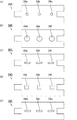
図3(a)、図3(b)、図3(c)及び図3(d)は、本発明の第一実施形態に係る保持シール材の別の一例を模式的に示す平面図である。
図3(a)、図3(b)、図3(c)及び図3(d)では、保持シール材に形成されている貫通部の断面の径の大きさ、又は、貫通部の断面の形状がそれぞれ異なる。
図3(a)に示す保持シール材10Bにおいて、貫通部14bの断面の形状は、図1に示した保持シール材10Aの貫通部14aの断面の形状と同様に、略円形状である。図3(a)に示す保持シール材10Bの貫通部14bの断面の径は、図1に示した保持シール材10Aの貫通部14aの断面の径よりも大きい。
また、図3(b)に示す保持シール材10C、図3(c)に示す保持シール材10D、及び、図3(d)に示す保持シール材10Eにおいて、貫通部14c、貫通部14d及び貫通部14eの断面の形状は、図1に示した保持シール材10Aの貫通部14aの断面の形状と異なり、それぞれ、略楕円形状、略正方形状、略長方形状である。
FIG. 3A, FIG. 3B, FIG. 3C, and FIG. 3D are plan views schematically showing another example of the holding sealing material according to the first embodiment of the present invention. .
3 (a), 3 (b), 3 (c), and 3 (d), the diameter of the cross section of the penetrating portion formed in the holding sealing material, or the cross section of the penetrating portion. Each shape is different.
In the
Further, in the holding sealing material 10C shown in FIG. 3B, the
本実施形態の保持シール材には、有機バインダ等のバインダが付与されていてもよい。保持シール材に付与されたバインダによって、保持シール材を構成する無機繊維同士を互いに固着することができる。従って、保持シール材をケーシングに圧入する際の保持シール材の嵩を低減させたり、無機繊維の飛散を防止したりすることができる。 The holding sealing material of this embodiment may be provided with a binder such as an organic binder. The inorganic fibers constituting the holding sealing material can be fixed to each other by the binder applied to the holding sealing material. Therefore, the bulk of the holding sealing material when the holding sealing material is press-fitted into the casing can be reduced, or scattering of inorganic fibers can be prevented.
本実施形態の保持シール材は、無機繊維から構成された素地マットに対してニードリング処理を施して得られるニードルマットであってもよい。
ニードリング処理とは、ニードル等の繊維交絡手段を素地マットに対して抜き差しする処理のことをいう。ニードリング処理が施された保持シール材では、比較的繊維長の長い無機繊維が3次元的に交絡する。そのため、ニードルマットの強度が向上することとなる。
The holding sealing material of the present embodiment may be a needle mat obtained by performing a needling process on a base mat composed of inorganic fibers.
The needling process refers to a process of inserting and removing a fiber entanglement means such as a needle with respect to the base mat. In the holding sealing material subjected to the needling treatment, inorganic fibers having a relatively long fiber length are entangled three-dimensionally. Therefore, the strength of the needle mat will be improved.
本実施形態の保持シール材の製造方法の一例について説明する。
例えば、紡糸法により、無機繊維を絡み合わせて作製した素地マットを所望の形状に打ち抜く方法等により保持シール材を製造した後、製造した保持シール材を打ち抜き刃等を用いて所定の形状に打ち抜くことにより貫通部を形成する方法、及び、素地マットを打ち抜く際に、貫通部も合わせて打ち抜く方法等が考えられる。
以上のような方法により、本実施形態の保持シール材を製造することができる。
An example of the manufacturing method of the holding sealing material of this embodiment will be described.
For example, after producing a holding sealing material by a method of punching a base mat produced by entanglement of inorganic fibers into a desired shape by a spinning method, the produced holding sealing material is punched into a predetermined shape using a punching blade or the like Thus, a method of forming the through portion, a method of punching the through portion together when punching the base mat, and the like can be considered.
The holding sealing material of this embodiment can be manufactured by the method as described above.
次に、本発明の第一実施形態に係る排ガス浄化装置について説明する。
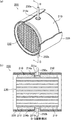
図4(a)は、本発明の第一実施形態に係る排ガス浄化装置の一例を模式的に示す一部切り欠き斜視断面図である。図4(b)は、図4(a)に示す排ガス浄化装置のA−A線断面図である。
図4(a)及び図4(b)に示す排ガス浄化装置100は、ケーシング120と、ケーシング120内に収容された排ガス処理体130と、排ガス処理体130及びケーシング120の間に配設された保持シール材110とを備えている。
排ガス浄化装置100は、排ガス処理体130と接続し、保持シール材110を通過し、かつ、ケーシング120を貫通するセンサー140aをさらに備えている。
保持シール材110は、排ガス処理体130の周囲に巻き付けられており、保持シール材110によって排ガス処理体130が保持されている。
ケーシング120の端部には、必要に応じて、内燃機関から排出された排ガスを導入する導入管と排ガス処理体を通過した排ガスが外部に排出される排出管とが接続される。
Next, the exhaust gas purification apparatus according to the first embodiment of the present invention will be described.
FIG. 4 (a) is a partially cutaway perspective sectional view schematically showing an example of the exhaust gas purifying apparatus according to the first embodiment of the present invention. FIG.4 (b) is the sectional view on the AA line of the exhaust gas purification apparatus shown to Fig.4 (a).
The exhaust
The exhaust
The holding
An end of the
本実施形態の排ガス浄化装置を構成する保持シール材について説明する。
本実施形態の排ガス浄化装置では、本実施形態の保持シール材が用いられている。
図4(a)及び図4(b)に示す排ガス浄化装置100では、保持シール材110として、図1に示した保持シール材10Aが用いられている例を示している。
図4(a)及び図4(b)に示すように、排ガス処理体130の周囲に巻き付けられた保持シール材110には、貫通部114aが形成されている。そして、この貫通部114aにセンサー140aが配置されている。
The holding sealing material constituting the exhaust gas purifying apparatus of the present embodiment will be described.
In the exhaust gas purification apparatus of the present embodiment, the holding sealing material of the present embodiment is used.
In the exhaust
As shown in FIG. 4A and FIG. 4B, a through-
本実施形態の排ガス浄化装置において、保持シール材の第1の端面及び第2の端面は、隙間なく当接していてもよいし、所定の隙間が形成されていてもよい。
保持シール材の当接部における第1の端面及び第2の端面の間に隙間が形成されていると、上記隙間に電極部材及び/又はセンサーを配置することができる。保持シール材の第1の端面及び第2の端面の間に隙間が形成されている場合、保持シール材の第1の端面と第2の端面との間の距離は、100mm以下であることが好ましく、20〜100mmであることがより好ましく、20〜40mmであることがさらに好ましい。保持シール材の第1の端面と第2の端面との間の距離が、100mmを超えると、排ガス処理体に接触する保持シール材の面積が少なくなるため、保持シール材が排ガス処理体を保持しにくくなる。保持シール材の当接部における第1の端面と第2の端面との間の距離が、20mm未満であると、隙間の大きさが小さすぎるため、上記隙間に電極部材及び/又はセンサーを配置しにくくなる。
In the exhaust gas purification apparatus of the present embodiment, the first end surface and the second end surface of the holding sealing material may be in contact with each other without a gap, or a predetermined gap may be formed.
When a gap is formed between the first end face and the second end face in the holding seal material contact portion, the electrode member and / or the sensor can be disposed in the gap. When a gap is formed between the first end surface and the second end surface of the holding sealing material, the distance between the first end surface and the second end surface of the holding sealing material may be 100 mm or less. It is preferably 20 to 100 mm, more preferably 20 to 40 mm. If the distance between the first end face and the second end face of the holding sealing material exceeds 100 mm, the area of the holding sealing material in contact with the exhaust gas treating body is reduced, so the holding sealing material holds the exhaust gas treating body. It becomes difficult to do. If the distance between the first end surface and the second end surface at the contact portion of the holding sealing material is less than 20 mm, the size of the gap is too small, and therefore the electrode member and / or sensor is arranged in the gap. It becomes difficult to do.
本実施形態の排ガス浄化装置を構成する排ガス処理体について説明する。
図5は、本発明の第一実施形態に係る排ガス浄化装置を構成する排ガス処理体の一例を模式的に示す斜視図である。
図5には、排ガス処理体の一例として、触媒担体の例を示している。
The exhaust gas treatment body constituting the exhaust gas purification apparatus of the present embodiment will be described.
FIG. 5 is a perspective view schematically showing an example of the exhaust gas treating body constituting the exhaust gas purifying apparatus according to the first embodiment of the present invention.
FIG. 5 shows an example of a catalyst carrier as an example of the exhaust gas treating body.
図5に示す排ガス処理体130は、主に多孔質セラミックからなり、その形状は略円柱状である。また、排ガス処理体130の外周には、排ガス処理体130の外周部を補強したり、形状を整えたり、排ガス処理体130の断熱性を向上させたりする目的で、コート層133が設けられている。なお、コート層は、必要に応じて設けられていればよい。
The exhaust
図5に示す排ガス処理体130は、隔壁132を隔てて長手方向(図5中、両矢印aで示した方向)に多数の貫通孔131が並設されたハニカム構造体となっている。
排ガス処理体130では、ハニカム構造体の隔壁132に、排ガス中に含まれるCO、HC、NOx等の有害なガス成分を浄化するための触媒が担持されている。上記触媒としては、例えば、白金等が挙げられる。
The exhaust
In the exhaust
本実施形態の排ガス浄化装置を構成するケーシングについて説明する。
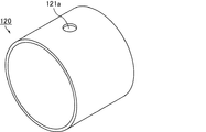
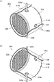
図6は、本発明の第一実施形態に係る排ガス浄化装置を構成するケーシングの一例を模式的に示す斜視図である。
図6に示すケーシング120は、主にステンレス等の金属からなり、その形状は、略円筒状である。ケーシング120には、センサーを貫通させるための孔121aが設けられている。
ケーシング120の内径は、図5に示す排ガス処理体130の端面の直径と、排ガス処理体130に巻き付けられた状態の保持シール材の厚さとを合わせた長さより若干短くなっている。
なお、ケーシングの長さは、排ガス処理体の長手方向における長さより若干長くなっていてもよいし、排ガス処理体の長手方向における長さと略同一であってもよい。
The casing which comprises the exhaust gas purification apparatus of this embodiment is demonstrated.
FIG. 6 is a perspective view schematically showing an example of a casing constituting the exhaust gas purifying apparatus according to the first embodiment of the present invention.
The
The inner diameter of the
Note that the length of the casing may be slightly longer than the length in the longitudinal direction of the exhaust gas treating body, or may be substantially the same as the length in the longitudinal direction of the exhaust gas treating body.
図4(a)及び図4(b)に示した排ガス浄化装置100において、保持シール材110の貫通部114aの位置は、ケーシング120の孔121aの位置と一致している。そして、センサー140aは、保持シール材110の貫通部114a及びケーシング120の孔121aに配置されている。
In the exhaust
本実施形態の排ガス浄化装置を構成するセンサーについて説明する。
本実施形態の排ガス浄化装置において、センサーの種類は特に限定されないが、例えば、排ガス浄化装置又は雰囲気の温度を測定するための温度センサー、酸素センサー等が挙げられる。
これらのセンサーは、保持シール材の貫通部に配置される限り、単独で用いられてもよいし、複数のセンサーを組み合わせて用いられてもよい。
The sensor which comprises the exhaust gas purification apparatus of this embodiment is demonstrated.
In the exhaust gas purifying apparatus of the present embodiment, the type of sensor is not particularly limited, and examples thereof include an exhaust gas purifying apparatus or a temperature sensor for measuring the temperature of the atmosphere, an oxygen sensor, and the like.
These sensors may be used alone or in combination with a plurality of sensors as long as they are arranged in the penetrating portion of the holding sealing material.
以下、本発明の第一実施形態に係る排ガス浄化装置の製造方法について、図面を参照しながら説明する。
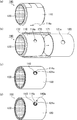
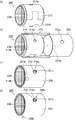
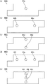
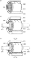
図7(a)、図7(b)、図7(c)及び図7(d)は、本発明の第一実施形態に係る排ガス浄化装置の製造方法の一例を模式的に示す斜視図である。
図7(a)、図7(b)、図7(c)及び図7(d)では、本発明の第一実施形態に係る排ガス浄化装置の製造方法の一例として、図4(a)及び図4(b)に示した排ガス浄化装置100の製造方法について説明する。
Hereinafter, a method for manufacturing an exhaust gas purifying apparatus according to a first embodiment of the present invention will be described with reference to the drawings.
7 (a), 7 (b), 7 (c) and 7 (d) are perspective views schematically showing an example of the method for manufacturing the exhaust gas purifying apparatus according to the first embodiment of the present invention. is there.
7 (a), 7 (b), 7 (c) and 7 (d), as an example of the method for manufacturing the exhaust gas purifying apparatus according to the first embodiment of the present invention, FIG. 4 (a) and FIG. A method for manufacturing the exhaust
まず、図7(a)に示すように、保持シール材110を排ガス処理体130の周囲に巻き付けることにより、巻付体(保持シール材が巻き付けられた排ガス処理体)160を作製する巻き付け工程を行う。
保持シール材110として、図1に示した保持シール材10Aを用いる。図7(a)において、保持シール材110には、貫通部114aが形成されている。
First, as shown in FIG. 7 (a), a winding process for producing a wound body (exhaust gas treatment body around which the holding seal material is wound) 160 by winding the holding
As the
次に、図7(b)に示すように、作製した巻付体160を、略円筒状のケーシング120に収容する収容工程を行う。
巻付体をケーシングに収容する方法としては、圧入方式(スタッフィング方式)、サイジング方式(スウェージング方式)、及び、クラムシェル方式等が挙げられる。
圧入方式(スタッフィング方式)では、圧入治具等を用いて、ケーシングの内部の所定の位置まで巻付体を圧入する。サイジング方式(スウェージング方式)では、巻付体をケーシングの内部に挿入した後、ケーシングの内径を縮めるように外周側から圧縮する。クラムシェル方式では、ケーシングを、第1のケーシング及び第2のケーシングの2つの部品に分離可能な形状としておき、巻付体を第1のケーシング上に載置した後に第2のケーシングを被せて密封する。
巻付体をケーシングに収容する方法の中では、圧入方式(スタッフィング方式)又はサイジング方式(スウェージング方式)が好ましい。圧入方式(スタッフィング方式)又はサイジング方式(スウェージング方式)では、ケーシングとして2つの部品を用いる必要がないため、製造工程の数を少なくすることができるからである。
Next, as shown in FIG. 7B, an accommodating process of accommodating the produced wound
Examples of the method for accommodating the wound body in the casing include a press-fitting method (stuffing method), a sizing method (swaging method), and a clamshell method.
In the press-fitting method (stuffing method), the wound body is press-fitted to a predetermined position inside the casing using a press-fitting jig or the like. In the sizing method (swaging method), the wound body is inserted into the casing and then compressed from the outer peripheral side so as to reduce the inner diameter of the casing. In the clamshell method, the casing is shaped so as to be separable into two parts, a first casing and a second casing, and the wound body is placed on the first casing and then covered with the second casing. Seal.
Among the methods for accommodating the wound body in the casing, the press-fitting method (stuffing method) or the sizing method (swaging method) is preferable. This is because in the press-fitting method (stuffing method) or the sizing method (swaging method), it is not necessary to use two parts as the casing, so the number of manufacturing processes can be reduced.
図7(b)では、圧入治具170を用いて、巻付体160をケーシング120に圧入する方法を示している。
圧入治具170は、全体として略円筒状であり、その内部が一端から他端に向かってテーパー状に広がっている。
圧入治具170の一端は、ケーシング120の内径よりわずかに小さな径に相当する内径を有する短径側端部171となっている。また、圧入治具170の他端は、少なくとも巻付体160の外径に相当する内径を有する長径側端部172となっている。
圧入治具170を用いることにより、巻付体160をケーシング120に容易に圧入することができる。
なお、巻付体をケーシングに圧入する方法としては特に限定されず、例えば、手で巻付体を押すことにより巻付体をケーシングに圧入する方法等であってもよい。
FIG. 7B shows a method of press-fitting the
The press-fitting
One end of the press-fitting
By using the press-fitting
In addition, it does not specifically limit as a method of press-fitting a winding body in a casing, For example, the method etc. which press-fit a winding body in a casing by pushing a winding body by hand etc. may be sufficient.
続いて、図7(c)に示すように、保持シール材110に形成された貫通部114aの位置を、ケーシング120の孔121aの位置に合わせる位置調整工程を行う。
貫通部の位置をケーシングの孔の位置に合わせる方法としては、例えば、ケーシングに収容された巻付体を回転する方法等が挙げられる。
なお、上記収容工程において、貫通部の位置とケーシングの位置とが一致するように巻付体をケーシングに収容する場合には、収容工程及び位置調整工程を同時に行うことができる。
Subsequently, as illustrated in FIG. 7C, a position adjustment process is performed in which the position of the through
Examples of a method for adjusting the position of the penetrating part to the position of the hole in the casing include a method of rotating a wound body accommodated in the casing.
In the housing step, when the wound body is housed in the casing so that the position of the penetrating part matches the position of the casing, the housing step and the position adjusting step can be performed simultaneously.
その後、排ガス処理体に接続し、保持シール材を通過し、かつ、ケーシングを貫通するようにセンサーを配置する配置工程(第1の配置工程)を行う。
図7(d)に示すように、配置工程(第1の配置工程)では、温度センサー等のセンサー140aを、保持シール材110に形成された貫通部114a及びケーシング120の孔121aに通し、上記センサー140aを排ガス処理体130に接続させる。
以上の工程を経ることにより、図4(a)及び図4(b)に示した排ガス浄化装置100を製造することができる。
Thereafter, an arrangement step (first arrangement step) is performed in which the sensor is arranged so as to connect to the exhaust gas treating body, pass through the holding sealing material, and penetrate the casing.
As shown in FIG. 7D, in the placement step (first placement step), a
Through the above steps, the exhaust
上記の本実施形態の排ガス浄化装置の製造方法では、巻付体をケーシングに収容した後に、センサーを貫通部及びケーシングの孔に配置している。
しかしながら、本実施形態の排ガス浄化装置の製造方法において、クラムシェル方式を採用する場合、第1のケーシング上に巻付体を載置し、センサーを貫通部に配置した後、第2のケーシングに設けられた孔をセンサーが通るように第2のケーシングを被せることにより、巻付体をケーシングに収容してもよい。
また、本実施形態の排ガス浄化装置の製造方法において、クラムシェル方式を採用する場合、排ガス処理体の所定の位置にセンサーを固定したものを準備しておき、センサーを貫通部に通して保持シール材を巻き付けることにより、センサー付き巻付体を作製してもよい。この場合、第1のケーシング上にセンサー付き巻付体を載置した後、第2のケーシングに設けられた孔をセンサーが通るように第2のケーシングを被せることにより、巻付体をケーシングに収容する。
In the manufacturing method of the exhaust gas purifying apparatus of the present embodiment described above, after the wound body is accommodated in the casing, the sensor is disposed in the through portion and the hole of the casing.
However, in the method of manufacturing the exhaust gas purifying apparatus of the present embodiment, when the clamshell method is adopted, the wound body is placed on the first casing, the sensor is disposed in the through portion, and then the second casing is placed. The wound body may be accommodated in the casing by covering the second casing so that the sensor passes through the provided hole.
In addition, in the method of manufacturing the exhaust gas purifying apparatus of the present embodiment, when the clamshell method is adopted, a sensor in which a sensor is fixed at a predetermined position of the exhaust gas treating body is prepared, and the sensor is passed through the penetrating portion to hold the seal A wound body with a sensor may be produced by winding a material. In this case, after placing the wound body with the sensor on the first casing, the second casing is put on the casing so that the sensor passes through the hole provided in the second casing. Accommodate.
以下に、本実施形態の保持シール材、排ガス浄化装置、及び、排ガス浄化装置の製造方法の作用効果について列挙する。
(1)本実施形態の保持シール材には、保持シール材の厚さ方向に貫通する貫通部が形成されている。従って、本実施形態の保持シール材を用いて排ガス浄化装置を製造する場合、上記保持シール材の貫通部にセンサーを配置することができる。
Below, it lists about the effect of the manufacturing method of the holding | maintenance sealing material of this embodiment, an exhaust gas purification apparatus, and an exhaust gas purification apparatus.
(1) In the holding sealing material of the present embodiment, a penetrating portion penetrating in the thickness direction of the holding sealing material is formed. Therefore, when manufacturing the exhaust gas purification apparatus using the holding sealing material of the present embodiment, a sensor can be disposed in the penetrating portion of the holding sealing material.
(2)本実施形態の保持シール材では、保持シール材の第1の端面及び第2の端面には、それぞれ、少なくとも1つの突出部からなる段差が設けられている。
保持シール材の第1の端面及び第2の端面にそれぞれ段差が設けられていると、突出部によって保持シール材が嵌合されやすくなるため、保持シール材の嵌合部から排ガスが漏れにくくなり、排ガスのシール性を保つことができる。また、保持シール材の第1の端面及び第2の端面にそれぞれ段差が設けられていると、保持シール材の突出部によって保持シール材が嵌合されやすくなるため、保持シール材の幅方向に排ガス浄化装置に力が加えられたとしても、排ガス処理体から保持シール材がずれにくくなる。
(2) In the holding sealing material of the present embodiment, the first end surface and the second end surface of the holding sealing material are each provided with a step including at least one projecting portion.
If the first end surface and the second end surface of the holding sealing material are stepped, the holding sealing material is easily fitted by the protruding portion, so that the exhaust gas hardly leaks from the fitting portion of the holding sealing material. The exhaust gas sealing performance can be maintained. In addition, when the first end surface and the second end surface of the holding sealing material are provided with steps, the holding sealing material is easily fitted by the protruding portion of the holding sealing material. Even if force is applied to the exhaust gas purification device, the holding sealing material is less likely to be displaced from the exhaust gas treating body.
(3)本実施形態の排ガス浄化装置、及び、排ガス浄化装置の製造方法では、本実施形態の保持シール材が用いられている。従って、保持シール材に形成されている貫通部に電極部材及び/又はセンサーを配置することができる。 (3) In the exhaust gas purifying apparatus and the manufacturing method of the exhaust gas purifying apparatus of the present embodiment, the holding sealing material of the present embodiment is used. Therefore, an electrode member and / or a sensor can be arranged in the penetrating portion formed in the holding sealing material.
(第二実施形態)
以下、本発明の一実施形態である第二実施形態について説明する。
本発明の第一実施形態に係る保持シール材、排ガス浄化装置、及び、排ガス浄化装置の製造方法では、保持シール材に1つの貫通部が形成されている。これに対して、本発明の第二実施形態に係る保持シール材、排ガス浄化装置、及び、排ガス浄化装置の製造方法では、保持シール材に2つの貫通部が形成されている。
(Second embodiment)
Hereinafter, a second embodiment which is an embodiment of the present invention will be described.
In the holding sealing material, the exhaust gas purifying apparatus, and the manufacturing method of the exhaust gas purifying apparatus according to the first embodiment of the present invention, one penetrating portion is formed in the holding sealing material. On the other hand, in the holding sealing material, the exhaust gas purifying apparatus, and the method for manufacturing the exhaust gas purifying apparatus according to the second embodiment of the present invention, two penetrating portions are formed in the holding sealing material.
本発明の第二実施形態に係る保持シール材について説明する。
図8は、本発明の第二実施形態に係る保持シール材の一例を模式的に示す斜視図である。
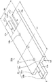
図8に示す保持シール材20Aは、アルミナ−シリカ繊維等の無機繊維からなり、マット状である。より詳細には、保持シール材20Aは、所定の長さ(図8中、矢印L2で示す)、幅(図8中、矢印W2で示す)、及び、厚さ(図8中、矢印T2で示す)を有する平面視略矩形の平板状の形状を有している。また、保持シール材20Aは、保持シール材20Aの幅W2方向に平行な第1の端面21(21a、21b及び21c)、並びに、第2の端面22(22a、22b及び22c)を有している。さらに、保持シール材20Aは、2つの貫通部24a及び24bを有している。
The holding sealing material according to the second embodiment of the present invention will be described.
FIG. 8 is a perspective view schematically showing an example of the holding sealing material according to the second embodiment of the present invention.
The holding
本実施形態の保持シール材では、上記第1の端面及び上記第2の端面には、それぞれ、少なくとも1つの突出部からなる段差が設けられている。
図8に示す保持シール材20Aでは、第1の端面21に2つの突出部23a及び23cが形成されており、第2の端面22に1つの突出部23bが形成されている。なお、保持シール材20Aの第1の端面21と第2の端面22とを当接させた際、突出部23bが形成する凸部と、突出部23a及び23cが形成する凹部とは嵌合される。
このように、図8に示す保持シール材20Aには、第1の端面21及び第2の端面22にそれぞれ3段の段差が設けられている。
In the holding sealing material of the present embodiment, the first end surface and the second end surface are each provided with a step including at least one protrusion.
In the holding sealing material 20 </ b> A shown in FIG. 8, two
As described above, the holding sealing material 20 </ b> A shown in FIG.
本実施形態の保持シール材では、保持シール材の長さ方向において、突出部の長さは略等しいことが好ましい。つまり、保持シール材のいずれの部分においても、第1の端面と第2の端面との距離が略等しいことが好ましい。
図8に示す保持シール材20Aでは、保持シール材20Aの長さL2方向において、突出部23aの長さ(図8中、矢印X4で示す)、突出部23bの長さ(図8中、矢印X5で示す)、及び、突出部23cの長さ(図8中、矢印X6で示す)がいずれも略等しくなっている。従って、図8に示す保持シール材20Aは、一定の長さL2を有している。
In the holding sealing material of this embodiment, it is preferable that the lengths of the protrusions are substantially equal in the length direction of the holding sealing material. That is, it is preferable that the distance between the first end surface and the second end surface is substantially equal in any part of the holding sealing material.
In the
本実施形態の保持シール材には、2つの貫通部が形成されている。また、保持シール材の2つの貫通部は、保持シール材の厚さ方向に保持シール材を貫通するように形成されている。 Two penetrating portions are formed in the holding sealing material of the present embodiment. Further, the two through portions of the holding sealing material are formed so as to penetrate the holding sealing material in the thickness direction of the holding sealing material.
本実施形態の保持シール材において、貫通部が形成されている位置は特に限定されないが、突出部以外の部分に形成されていることが好ましい。保持シール材を製造するための収容工程において、保持シール材の突出部が変形しにくくなるためである。 In the holding sealing material of the present embodiment, the position where the penetrating portion is formed is not particularly limited, but is preferably formed in a portion other than the protruding portion. This is because the protrusion of the holding sealing material is unlikely to be deformed in the housing step for manufacturing the holding sealing material.
本実施形態の保持シール材においては、2つの貫通部が、保持シール材の幅方向の中心線に対して線対称となる位置、保持シール材の長さ方向の中心線に対して線対称となる位置、又は、保持シール材の中心に対して点対称となる位置に形成されていることが好ましい。
本明細書において、「保持シール材の長さ方向の中心線」とは、保持シール材の幅を二等分する線(図8中、一点鎖線Xで示す)をいう。「保持シール材の幅方向の中心線」とは、突出部を除いた保持シール材の長さ(図8中、L2−X4又はL2−X6で表される長さ)を二等分する線(図8中、一点鎖線Yで示す)をいう。「保持シール材の中心」とは、保持シール材の長さ方向の中心線と保持シール材の幅方向の中心線との交点(図8中、点Oで示す)をいう。
In the holding sealing material of the present embodiment, the two penetrating portions are symmetrical with respect to the center line in the width direction of the holding sealing material, and are symmetrical with respect to the center line in the length direction of the holding sealing material. Or a position that is point-symmetric with respect to the center of the holding sealing material.
In this specification, the “center line in the length direction of the holding sealing material” refers to a line (indicated by a dashed line X in FIG. 8) that bisects the width of the holding sealing material. The “center line in the width direction of the holding sealing material” is the length of the holding sealing material excluding the protruding portion (the length represented by L 2 -X 4 or L 2 -X 6 in FIG. 8). A line equally dividing (indicated by a one-dot chain line Y in FIG. 8). The “center of the holding sealing material” refers to an intersection (indicated by a point O in FIG. 8) between the center line in the length direction of the holding sealing material and the center line in the width direction of the holding sealing material.
本実施形態の保持シール材においては、2つの貫通部が、保持シール材の幅方向の中心線に対して線対称となる位置に形成されていることがより好ましく、この場合、保持シール材の2つの貫通部間の距離は、保持シール材の長さの50%であることが好ましい。
保持シール材の2つの貫通部が、保持シール材の幅方向の中心線に対して線対称となる位置に形成されており、かつ、保持シール材の2つの貫通部間の距離が、保持シール材の長さの50%であると、この保持シール材を用いて排ガス浄化装置を製造した場合に、排ガス処理体を介して、保持シール材の2つの貫通部が正対する。
なお、「2つの貫通部が正対する」とは、排ガス処理体の周囲に巻き付けられた状態における保持シール材の2つの貫通部が、排ガス処理体の長手方向に平行な断面においては、当該断面の排ガス処理体の長手方向の中心線に対して線対称に位置し、かつ、排ガス処理体の長手方向に垂直な断面においては、当該断面の中心に対して点対称に位置することを意味する。
In the holding sealing material of the present embodiment, it is more preferable that the two penetrating portions are formed at positions that are line-symmetric with respect to the center line in the width direction of the holding sealing material. The distance between the two penetrating portions is preferably 50% of the length of the holding sealing material.
The two penetrating portions of the holding sealing material are formed at positions that are line-symmetric with respect to the center line in the width direction of the holding sealing material, and the distance between the two penetrating portions of the holding sealing material is the holding seal. When the exhaust gas purification device is manufactured using this holding sealing material, the two through portions of the holding sealing material face each other through the exhaust gas treating body.
“Two penetrations face each other” means that the two penetrations of the holding sealing material wound around the exhaust gas treatment body are in a cross section parallel to the longitudinal direction of the exhaust gas treatment body. In the cross section perpendicular to the longitudinal direction of the exhaust gas treatment body, it is located point-symmetrically with respect to the center of the cross section. .
本実施形態の保持シール材において、保持シール材の貫通部の形状としては、例えば、略円柱状、略角柱状、略楕円柱状、略円錐台状、略直線と略円弧で囲まれた底面を有する柱状等が挙げられ、貫通部の断面の形状としては、例えば、略円形状、略四角形状等の略多角形状、略楕円形状、略長円形状(略レーストラック形状)等が挙げられる。
本実施形態の保持シール材を用いて排ガス浄化装置を製造する場合、保持シール材の貫通部の断面の形状を電極部材等の断面形状に合わせることができる。
本実施形態の保持シール材においては、保持シール材の貫通部が2つ形成されているが、2つの上記貫通部の形状及び大きさは、それぞれ略同一であってもよいし、異なっていてもよい。
In the holding sealing material of the present embodiment, the shape of the penetrating portion of the holding sealing material is, for example, a substantially cylindrical shape, a substantially rectangular column shape, a substantially elliptical column shape, a substantially truncated cone shape, a bottom surface surrounded by a substantially straight line and a substantially arc shape. Examples of the cross-sectional shape of the penetrating portion include a substantially circular shape, a substantially polygonal shape such as a substantially square shape, a substantially elliptical shape, a substantially oval shape (a substantially racetrack shape), and the like.
When manufacturing the exhaust gas purification apparatus using the holding sealing material of the present embodiment, the cross-sectional shape of the penetrating portion of the holding sealing material can be matched with the cross-sectional shape of the electrode member or the like.
In the holding sealing material of the present embodiment, two through portions of the holding sealing material are formed, but the shape and size of the two through portions may be substantially the same or different from each other. Also good.
本実施形態の保持シール材において、保持シール材の貫通部の断面の径は、1〜100mmであることが好ましく、20〜40mmであることがより好ましい。
保持シール材の貫通部の断面の径が、1mm未満であると、保持シール材を排ガス浄化装置に用いる際に、保持シール材の貫通部に電極部材及び/又はセンサーを配置することが困難である。一方、保持シール材の貫通部の断面の径が、100mmを超えると、保持シール材の面積が小さくなりすぎるため、保持シール材の保持力が低下してしまう。また、貫通部の断面の径が、100mmを超えると、保持シール材の幅方向に占める保持シール材の面積が減少するために、保持シール材の引っ張り強度が低下してしまう。
また、本実施形態の保持シール材において、保持シール材の貫通部の断面の面積は、1〜10000mm2であることが好ましく、400〜1600mm2であることがより好ましい。
保持シール材の貫通部の断面の面積が、1mm2未満であると、保持シール材を排ガス浄化装置に用いる際に、電極部材及び/又はセンサーを配置するために充分な面積を確保することができない。一方、保持シール材の貫通部の断面の面積が、10000mm2を超えると、保持シール材の面積が小さくなりすぎるため、保持シール材の保持力が低下してしまう。
In the holding sealing material of the present embodiment, the diameter of the cross section of the penetrating portion of the holding sealing material is preferably 1 to 100 mm, and more preferably 20 to 40 mm.
When the diameter of the cross section of the through portion of the holding sealing material is less than 1 mm, it is difficult to dispose the electrode member and / or sensor in the through portion of the holding sealing material when the holding sealing material is used in an exhaust gas purification device. is there. On the other hand, if the diameter of the cross section of the penetrating portion of the holding sealing material exceeds 100 mm, the area of the holding sealing material becomes too small, and the holding force of the holding sealing material is reduced. Moreover, since the area of the holding sealing material which occupies in the width direction of a holding sealing material will reduce when the diameter of the cross section of a penetration part exceeds 100 mm, the tensile strength of a holding sealing material will fall.
Further, in the holding sealing material of the present embodiment, the area of the cross section of the penetration portion of the holding sealing material is preferably 1~10000Mm 2, more preferably 400~1600mm 2.
When the area of the cross section of the penetrating portion of the holding sealing material is less than 1 mm 2 , it is possible to secure a sufficient area for arranging the electrode member and / or sensor when the holding sealing material is used in the exhaust gas purification device. Can not. On the other hand, if the cross-sectional area of the penetrating portion of the holding sealing material exceeds 10,000 mm 2 , the holding sealing material has an area that is too small, and the holding force of the holding sealing material is reduced.
図8に示す保持シール材20Aにおいて、2つの貫通部24a及び24bの形状は、ともに略円柱状であり、2つの貫通部24a及び24bの断面の形状は、ともに略円形状である。
保持シール材の貫通部24a及び24bは、保持シール材の幅方向の中心線に対して線対称となる位置に形成されているということもできるし、保持シール材の中心に対して点対称となる位置に形成されているということもできる。
In the
The through
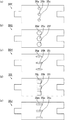
図9(a)、図9(b)、図9(c)、図9(d)及び図9(e)は、本発明の第二実施形態に係る保持シール材の別の一例を模式的に示す平面図である。
図9(a)、図9(b)、図9(c)、図9(d)及び図9(e)では、いずれも、保持シール材に形成されている2つの貫通部が、保持シール材の幅方向の中心線に対して線対称となる位置に形成されているということもできるし、保持シール材の中心に対して点対称となる位置に形成されているということもできる。そして、保持シール材に形成されている貫通部の断面の径の大きさ、又は、貫通部の断面の形状がそれぞれ異なる。
図9(a)に示す保持シール材20Bにおいて、貫通部24c及び24dの断面の形状は、図8に示した保持シール材20Aの貫通部24a及び24bの断面の形状と同様に、ともに略円形状である。図9(a)に示す保持シール材20Bの貫通部24c及び24dの断面の径は、図8に示した保持シール材20Aの貫通部24a及び24bの断面の径よりも大きい。
また、図9(b)に示す保持シール材20C、図9(c)に示す保持シール材20D、及び、図9(d)に示す保持シール材20Eにおいて、貫通部24e及び24f、貫通部24g及び24h、並びに、貫通部24i及び24jの断面の形状は、図8に示した保持シール材20Aの貫通部24a及び24bの断面の形状と異なり、それぞれ、略楕円形状、略正方形状、略長方形状である。
さらに、図9(e)に示す保持シール材20Fにおいて、貫通部24kの断面の形状は、略円形状であり、貫通部24lの断面の形状は、略長方形状である。図9(e)に示す保持シール材20F、及び、大きさが同じ2つの孔が設けられたケーシングを用いて排ガス浄化装置を製造する場合、ケーシングの孔の位置と貫通部の位置とを容易に調整することができる。なぜなら、ケーシングの第1の孔の位置を貫通部24kの位置に合わせると、ケーシングの第2の孔の位置は、貫通部24lの一部と重複する位置に合わせればよい。つまり、ケーシングの第2の孔の位置を厳密に調整する必要がないため、ケーシングの孔の位置と貫通部の位置とを容易に調整することができる。
FIG. 9A, FIG. 9B, FIG. 9C, FIG. 9D, and FIG. 9E are schematic examples of another example of the holding sealing material according to the second embodiment of the present invention. FIG.
9 (a), 9 (b), 9 (c), 9 (d), and 9 (e), the two penetrating portions formed in the holding sealing material are all holding seals. It can also be said that it is formed at a position that is line-symmetric with respect to the center line in the width direction of the material, or can be formed at a position that is point-symmetric with respect to the center of the holding sealing material. And the magnitude | size of the diameter of the cross section of the penetration part currently formed in the holding sealing material, or the shape of the cross section of a penetration part differs.
In the
Further, in the holding sealing material 20C shown in FIG. 9B, the
Furthermore, in the
図10(a)、図10(b)、図10(c)、図10(d)及び図10(e)は、本発明の第二実施形態に係る保持シール材のさらに別の一例を模式的に示す平面図である。
図10(a)、図10(b)、図10(c)、図10(d)及び図10(e)では、いずれも、保持シール材に形成されている2つの貫通部が、保持シール材の長さ方向の中心線に対して線対称となる位置に形成されているということもできるし、保持シール材の中心に対して点対称となる位置に形成されているということもできる。そして、保持シール材に形成されている貫通部の断面の径の大きさ、又は、貫通部の断面の形状がそれぞれ異なる。
図10(a)に示す保持シール材20Gにおいて、貫通部24m及び24nの断面の形状は、ともに略円形状である。
図10(b)に示す保持シール材20Hにおいて、貫通部24o及び24pの断面の形状は、図10(a)に示す保持シール材20Gの貫通部24m及び24nの断面の形状と同様に、ともに略円形状である。図10(b)に示す保持シール材20Hの貫通部24o及び24pの断面の径は、図10(a)に示す保持シール材20Gの貫通部24m及び24nの断面の径よりも大きい。
また、図10(c)に示す保持シール材20I、図10(d)に示す保持シール材20J、及び、図10(e)に示す保持シール材20Kにおいて、貫通部24q及び24r、貫通部24s及び24t、並びに、貫通部24u及び24vの断面の形状は、図10(a)に示す保持シール材20Gの貫通部24m及び24nの断面の形状と異なり、それぞれ、略楕円形状、略正方形状、略長方形状である。
10 (a), 10 (b), 10 (c), 10 (d), and 10 (e) are schematic diagrams of still another example of the holding sealing material according to the second embodiment of the present invention. FIG.
10 (a), 10 (b), 10 (c), 10 (d), and 10 (e), the two penetrating portions formed in the holding sealing material are all holding seals. It can also be said that it is formed at a position that is line-symmetric with respect to the center line in the length direction of the material, or can be formed at a position that is point-symmetric with respect to the center of the holding sealing material. And the magnitude | size of the diameter of the cross section of the penetration part currently formed in the holding sealing material, or the shape of the cross section of a penetration part differs.
In the
In the
Further, in the holding sealing material 20I shown in FIG. 10 (c), the
本実施形態の保持シール材には、有機バインダ等のバインダが付与されていてもよい。
また、本実施形態の保持シール材は、無機繊維から構成された素地マットに対してニードリング処理を施して得られるニードルマットであってもよい。
The holding sealing material of this embodiment may be provided with a binder such as an organic binder.
Further, the holding sealing material of the present embodiment may be a needle mat obtained by performing a needling process on a base mat composed of inorganic fibers.
本実施形態の保持シール材の製造方法は、保持シール材に形成する貫通部の個数が異なる以外は、本発明の第一実施形態に係る保持シール材の製造方法と同様である。 The manufacturing method of the holding sealing material of this embodiment is the same as the manufacturing method of the holding sealing material according to the first embodiment of the present invention, except that the number of penetrating portions formed in the holding sealing material is different.
次に、本発明の第二実施形態に係る排ガス浄化装置について説明する。
図11(a)は、本発明の第二実施形態に係る排ガス浄化装置の一例を模式的に示す一部切り欠き斜視断面図である。図11(b)は、図11(a)に示す排ガス浄化装置のB−B線断面図である。
図11(a)及び図11(b)に示す排ガス浄化装置200は、ケーシング220と、ケーシング220内に収容された排ガス処理体230と、排ガス処理体230及びケーシング220の間に配設された保持シール材210とを備えている。
排ガス浄化装置200は、排ガス処理体230と接続し、保持シール材210を通過し、かつ、ケーシング220を貫通する電極部材250a及び250bをさらに備えている。なお、電極部材250aは+側の電極部材であり、電極部材250bは−側の電極部材である。
保持シール材210は、排ガス処理体230の周囲に巻き付けられており、保持シール材210によって排ガス処理体230が保持されている。
ケーシング220の端部には、必要に応じて、内燃機関から排出された排ガスを導入する導入管と排ガス処理体を通過した排ガスが外部に排出される排出管とが接続される。
Next, an exhaust gas purification apparatus according to the second embodiment of the present invention will be described.
FIG. 11A is a partially cutaway perspective sectional view schematically showing an example of the exhaust gas purifying apparatus according to the second embodiment of the present invention. FIG.11 (b) is the BB sectional drawing of the exhaust gas purification apparatus shown to Fig.11 (a).
The exhaust
The exhaust
The holding
An end of the
本実施形態の排ガス浄化装置は、電気加熱コンバータとして使用することができる。
図11(a)及び図11(b)に示す排ガス浄化装置200において、+側の電極部材250aと−側の電極部材250bとの間に所定の電圧を印加すると、+側の電極部材250aと−側の電極部材250bとの間に介在する排ガス処理体230が通電されて発熱する。
これにより、排ガス処理体230に担持されている触媒が加熱されて活性化される。その結果、排ガス中に含まれるCO、HC、NOx等の有害なガス成分が、酸化、還元反応が促進されることにより浄化される。
The exhaust gas purification apparatus of this embodiment can be used as an electric heating converter.
In the exhaust
As a result, the catalyst carried on the exhaust
本実施形態の排ガス浄化装置を構成する保持シール材について説明する。
本実施形態の排ガス浄化装置では、本実施形態の保持シール材が用いられている。
図11(a)及び図11(b)に示す排ガス浄化装置200では、保持シール材210として、図8に示した保持シール材20Aが用いられている例を示している。
図11(a)及び図11(b)に示すように、排ガス処理体230の周囲に巻き付けられた保持シール材210には、貫通部214a及び214bが形成されている。そして、図11(a)及び図11(b)に示す排ガス浄化装置200では、保持シール材の貫通部214aに+側の電極部材250aが配置されており、保持シール材の貫通部214bには、−側の電極部材250bが配置されている。
なお、本実施形態の排ガス浄化装置では、+側の電極部材及び−側の電極部材は、保持シール材のどちらの貫通部に配置されていてもよい。
The holding sealing material constituting the exhaust gas purifying apparatus of the present embodiment will be described.
In the exhaust gas purification apparatus of the present embodiment, the holding sealing material of the present embodiment is used.
In the exhaust
As shown in FIGS. 11A and 11B, the
In the exhaust gas purifying apparatus of the present embodiment, the + side electrode member and the − side electrode member may be disposed in any penetrating portion of the holding sealing material.
本実施形態の排ガス浄化装置において、保持シール材の第1の端面及び第2の端面は、隙間なく当接していてもよいし、所定の隙間が形成されていてもよい。
保持シール材の当接部における第1の端面及び第2の端面の間に隙間が形成されていると、上記隙間に電極部材及び/又はセンサーを配置することができる。保持シール材の第1の端面及び第2の端面の間に隙間が形成されている場合、保持シール材の第1の端面と第2の端面との間の距離は、100mm以下であることが好ましく、20〜100mmであることがより好ましく、20〜40mmであることがさらに好ましい。保持シール材の第1の端面と第2の端面との間の距離が、100mmを超えると、排ガス処理体に接触する保持シール材の面積が少なくなるため、保持シール材が排ガス処理体を保持しにくくなる。保持シール材の当接部における第1の端面と第2の端面との間の距離が、20mm未満であると、隙間の大きさが小さすぎるため、上記隙間に電極部材及び/又はセンサーを配置しにくくなる。
In the exhaust gas purification apparatus of the present embodiment, the first end surface and the second end surface of the holding sealing material may be in contact with each other without a gap, or a predetermined gap may be formed.
When a gap is formed between the first end face and the second end face in the holding seal material contact portion, the electrode member and / or the sensor can be disposed in the gap. When a gap is formed between the first end surface and the second end surface of the holding sealing material, the distance between the first end surface and the second end surface of the holding sealing material may be 100 mm or less. It is preferably 20 to 100 mm, more preferably 20 to 40 mm. If the distance between the first end face and the second end face of the holding sealing material exceeds 100 mm, the area of the holding sealing material in contact with the exhaust gas treating body is reduced, so the holding sealing material holds the exhaust gas treating body. It becomes difficult to do. If the distance between the first end surface and the second end surface at the contact portion of the holding sealing material is less than 20 mm, the size of the gap is too small, and therefore the electrode member and / or sensor is arranged in the gap. It becomes difficult to do.
本実施形態の排ガス浄化装置を構成する排ガス処理体としては、本発明の第一実施形態で説明した排ガス処理体を使用することができる。 As the exhaust gas treating body constituting the exhaust gas purifying apparatus of the present embodiment, the exhaust gas treating body described in the first embodiment of the present invention can be used.
本実施形態の排ガス浄化装置を構成するケーシングについて説明する。
図12は、本発明の第二実施形態に係る排ガス浄化装置を構成するケーシングの一例を模式的に示す斜視図である。
図12に示すケーシング220は、主にステンレス等の金属からなり、その形状は、略円筒状である。ケーシング220には、電極部材を貫通させるための孔221a及び221bが設けられている。
ケーシング220の内径は、排ガス処理体の端面の直径と、排ガス処理体に巻き付けられた状態の保持シール材の厚さとを合わせた長さより若干短くなっている。
また、ケーシングの長さは、排ガス処理体の長手方向における長さより若干長くなっていてもよいし、排ガス処理体の長手方向における長さと略同一であってもよい。
The casing which comprises the exhaust gas purification apparatus of this embodiment is demonstrated.
FIG. 12 is a perspective view schematically showing an example of a casing constituting the exhaust gas purifying apparatus according to the second embodiment of the present invention.
The
The inner diameter of the
Further, the length of the casing may be slightly longer than the length in the longitudinal direction of the exhaust gas treating body, or may be substantially the same as the length in the longitudinal direction of the exhaust gas treating body.
図11(a)及び図11(b)に示した排ガス浄化装置200において、保持シール材210の貫通部214aの位置は、ケーシング220の孔221aの位置と一致しており、保持シール材210の貫通部214bの位置は、ケーシング220の孔221bの位置と一致している。そして、+側の電極部材250aは、保持シール材210の貫通部214a及びケーシング220の孔221aに配置されており、−側の電極部材250bは、保持シール材210の貫通部214b及びケーシング220の孔221bに配置されている。
In the exhaust
本実施形態の排ガス浄化装置を構成する電極部材について説明する。
電極部材には、バッテリー電源が接続されており、バッテリー電源から直接電圧が印加される。これにより、電極部材と接続する排ガス処理体に電流を流すことができる。
電極部材を配置する位置は特に限定されないが、排ガス処理体を効率良く加熱することを考慮すると、+側の電極部材と−側の電極部材とが対向する位置に配置することが好ましい。
The electrode member which comprises the exhaust gas purification apparatus of this embodiment is demonstrated.
A battery power source is connected to the electrode member, and a voltage is directly applied from the battery power source. Thereby, an electric current can be sent through the exhaust gas treating body connected to the electrode member.
The position where the electrode member is disposed is not particularly limited, but it is preferable that the electrode member on the + side and the electrode member on the − side face each other in consideration of efficiently heating the exhaust gas treating body.
本実施形態の排ガス浄化装置において、保持シール材の2つの貫通部には、電極部材が配置される代わりに、本発明の第一実施形態に係る排ガス浄化装置と同様、温度センサー、酸素センサー等のセンサーがそれぞれ配置されていてもよい。 In the exhaust gas purifying apparatus of the present embodiment, an electrode member is disposed in the two penetrating portions of the holding sealing material, similarly to the exhaust gas purifying apparatus according to the first embodiment of the present invention, a temperature sensor, an oxygen sensor, etc. The sensors may be arranged respectively.
以下、本発明の第二実施形態に係る排ガス浄化装置の製造方法について、図面を参照しながら説明する。
図13(a)、図13(b)、図13(c)及び図13(d)は、本発明の第二実施形態に係る排ガス浄化装置の製造方法の一例を模式的に示す斜視図である。
図13(a)、図13(b)、図13(c)及び図13(d)では、本発明の第二実施形態に係る排ガス浄化装置の製造方法の一例として、図11(a)及び図11(b)に示した排ガス浄化装置200の製造方法について説明する。
Hereinafter, a method for manufacturing an exhaust gas purifying apparatus according to a second embodiment of the present invention will be described with reference to the drawings.
FIGS. 13 (a), 13 (b), 13 (c) and 13 (d) are perspective views schematically showing an example of a method for manufacturing an exhaust gas purifying apparatus according to the second embodiment of the present invention. is there.
13 (a), FIG. 13 (b), FIG. 13 (c) and FIG. 13 (d), as an example of the method for manufacturing the exhaust gas purifying apparatus according to the second embodiment of the present invention, FIG. A method for manufacturing the exhaust
まず、図13(a)に示すように、保持シール材210を排ガス処理体230の周囲に巻き付けることにより、巻付体(保持シール材が巻き付けられた排ガス処理体)260を作製する巻き付け工程を行う。
保持シール材210として、図8に示した保持シール材20Aを用いる。図13(a)において、保持シール材210には、貫通部214a及び214bが形成されている。
First, as shown in FIG. 13 (a), a winding process for producing a wound body (exhaust gas treatment body around which the holding seal material is wound) 260 is performed by winding the holding
As the
次に、図13(b)に示すように、作製した巻付体260を、略円筒状のケーシング220に収容する収容工程を行う。
巻付体をケーシングに収容する方法としては、本発明の第一実施形態で説明した圧入方式(スタッフィング方式)、サイジング方式(スウェージング方式)、及び、クラムシェル方式等が挙げられる。
巻付体をケーシングに収容する方法の中では、圧入方式(スタッフィング方式)又はサイジング方式(スウェージング方式)が好ましい。圧入方式(スタッフィング方式)又はサイジング方式(スウェージング方式)では、ケーシングとして2つの部品を用いる必要がないため、製造工程の数を少なくすることができるからである。
Next, as shown in FIG. 13 (b), an accommodating step of accommodating the produced wound
Examples of the method for accommodating the wound body in the casing include the press-fitting method (stuffing method), the sizing method (swaging method), and the clamshell method described in the first embodiment of the present invention.
Among the methods for accommodating the wound body in the casing, the press-fitting method (stuffing method) or the sizing method (swaging method) is preferable. This is because in the press-fitting method (stuffing method) or the sizing method (swaging method), it is not necessary to use two parts as the casing, so the number of manufacturing processes can be reduced.
図13(b)では、圧入治具270を用いて、巻付体260をケーシング220に圧入する方法を示している。
圧入治具270は、本発明の第一実施形態で説明した圧入治具170と同様の構成を有している。
なお、巻付体をケーシングに圧入する方法としては特に限定されず、例えば、手で巻付体を押すことにより巻付体をケーシングに圧入する方法等であってもよい。
FIG. 13B shows a method of press-fitting the
The press-fitting
In addition, it does not specifically limit as a method of press-fitting a winding body in a casing, For example, the method etc. which press-fit a winding body in a casing by pushing a winding body by hand etc. may be sufficient.
続いて、図13(c)に示すように、保持シール材210に形成された貫通部214a及び214bの位置を、それぞれ、ケーシング220の孔221a及び221bの位置に合わせる位置調整工程を行う。
貫通部の位置をケーシングの孔の位置に合わせる方法としては、例えば、ケーシングに収容された巻付体を回転する方法等が挙げられる。
なお、上記収容工程において、貫通部の位置とケーシングの位置とが一致するように巻付体をケーシングに収容する場合には、収容工程及び位置調整工程を同時に行うことができる。
Subsequently, as shown in FIG. 13C, a position adjusting step is performed in which the positions of the through
Examples of a method for adjusting the position of the penetrating part to the position of the hole in the casing include a method of rotating a wound body accommodated in the casing.
In the housing step, when the wound body is housed in the casing so that the position of the penetrating part matches the position of the casing, the housing step and the position adjusting step can be performed simultaneously.
その後、排ガス処理体に接続し、保持シール材を通過し、かつ、ケーシングを貫通するように電極部材を配置する第1の配置工程、及び、排ガス処理体に接続し、保持シール材を通過し、かつ、ケーシングを貫通するように別の電極部材を配置する第2の配置工程を行う。
図13(d)に示すように、第1の配置工程では、ケーシング220に設けられた一方の孔221a、及び、保持シール材210に形成された貫通部214aに、+側の電極部材250aを通し、上記+側の電極部材250aを排ガス処理体230に接続させる。また、第2の配置工程では、ケーシング220に設けられた他方の孔221b、及び、保持シール材210に形成された貫通部214bに、−側の電極部材250bを通し、上記−側の電極部材250bを排ガス処理体230に接続させる。
なお、第1の配置工程及び第2の配置工程は、位置調整工程の後(収容工程及び位置調整工程を同時に行う場合には、収容工程の後)であれば、どちらを先に行ってもよい。
以上の工程を経ることにより、図11(a)及び図11(b)に示した排ガス浄化装置200を製造することができる。
Thereafter, the first arrangement step of connecting the exhaust gas treatment body, passing through the holding sealing material and arranging the electrode member so as to penetrate the casing, and connecting to the exhaust gas treatment body, passing through the holding sealing material. And the 2nd arrangement | positioning process which arrange | positions another electrode member so that a casing may be penetrated is performed.
As shown in FIG. 13 (d), in the first arrangement step, the +
In addition, as long as the 1st arrangement | positioning process and the 2nd arrangement | positioning process are after a position adjustment process (when the accommodation process and the position adjustment process are performed simultaneously, after an accommodation process), whichever is performed first. Good.
Through the above steps, the exhaust
上記の本実施形態の排ガス浄化装置の製造方法では、巻付体をケーシングに収容した後に、2つの電極部材を異なる貫通部及びケーシングの孔に配置している。
しかしながら、本実施形態の排ガス浄化装置の製造方法において、クラムシェル方式を採用する場合、孔が設けられた第1のケーシング上に、保持シール材の一方の貫通部と第1のケーシングの孔の位置が合うように巻付体を載置し、+側の電極部材を保持シール材の他方の貫通部に配置し、−側の電極部材を保持シール材の一方の貫通部及び第1のケーシングの孔に配置した後、第2のケーシングに設けられた孔を+側の電極部材が通るように第2のケーシングを被せることにより、巻付体をケーシングに収容してもよい。
また、本実施形態の排ガス浄化装置の製造方法において、クラムシェル方式を採用する場合、排ガス処理体の所定の位置に+側の電極部材及び−側の電極部材を固定したものを準備しておき、−側の電極部材を保持シール材の一方の貫通部に通し、+側の電極部材を保持シール材の他方の貫通部に通して保持シール材を巻き付けることにより、電極部材付き巻付体を作製してもよい。この場合、孔が設けられた第1のケーシング上に、−側の電極部材が通るように電極部材付き巻付体を載置した後、第2のケーシングに設けられた孔を+側の電極部材が通るように第2のケーシングを被せることにより、巻付体をケーシングに収容する。
In the method for manufacturing the exhaust gas purification apparatus of the present embodiment, after the wound body is accommodated in the casing, the two electrode members are arranged in different through portions and holes of the casing.
However, in the method of manufacturing the exhaust gas purifying apparatus according to the present embodiment, when the clamshell method is adopted, the one through portion of the holding sealing material and the hole of the first casing are formed on the first casing provided with the hole. The wound body is placed so that the positions are aligned, the + -side electrode member is disposed in the other penetrating portion of the holding sealing material, and the −-side electrode member is placed in one penetrating portion of the holding sealing material and the first casing After arranging in the hole, the wound body may be accommodated in the casing by covering the second casing so that the positive electrode member passes through the hole provided in the second casing.
In addition, when the clamshell method is employed in the method for manufacturing an exhaust gas purification apparatus of this embodiment, a device in which a positive electrode member and a negative electrode member are fixed at predetermined positions of an exhaust gas treatment body is prepared. The winding member with the electrode member is wound by passing the + side electrode member through one penetration part of the holding sealing material and winding the + side electrode member through the other penetration part of the holding sealing material and winding the holding sealing material. It may be produced. In this case, after placing the wound member with the electrode member on the first casing provided with the hole so that the negative electrode member passes, the hole provided in the second casing is changed to the positive electrode. By covering the second casing so that the member passes, the wound body is accommodated in the casing.
本実施形態では、本発明の第一実施形態において説明した効果(1)〜(3)を発揮することができるとともに、以下の効果を発揮することができる。
(4)本実施形態の排ガス浄化装置では、電極部材を配置することができるため、本実施形態の排ガス浄化装置を電気加熱触媒コンバータとして使用することができる。
In the present embodiment, the effects (1) to (3) described in the first embodiment of the present invention can be exhibited, and the following effects can be exhibited.
(4) In the exhaust gas purification apparatus of this embodiment, since an electrode member can be arranged, the exhaust gas purification apparatus of this embodiment can be used as an electrically heated catalytic converter.
(第三実施形態)
以下、本発明の一実施形態である第三実施形態について説明する。
本発明の第一実施形態に係る保持シール材、排ガス浄化装置、及び、排ガス浄化装置の製造方法では、保持シール材に1つの貫通部が形成されており、本発明の第二実施形態に係る保持シール材、排ガス浄化装置、及び、排ガス浄化装置の製造方法では、保持シール材に2つの貫通部が形成されている。これに対して、本発明の第三実施形態に係る保持シール材、排ガス浄化装置、及び、排ガス浄化装置の製造方法では、保持シール材に3つの貫通部が形成されている。
(Third embodiment)
Hereinafter, a third embodiment which is an embodiment of the present invention will be described.
In the holding sealing material, the exhaust gas purification device, and the exhaust gas purification device manufacturing method according to the first embodiment of the present invention, one through portion is formed in the holding sealing material, and the second embodiment of the present invention is concerned. In the holding sealing material, the exhaust gas purification device, and the manufacturing method of the exhaust gas purification device, two through portions are formed in the holding sealing material. In contrast, in the holding sealing material, the exhaust gas purification device, and the exhaust gas purification device manufacturing method according to the third embodiment of the present invention, three through portions are formed in the holding sealing material.
まず、本発明の第三実施形態に係る保持シール材について説明する。
本発明の第三実施形態に係る保持シール材は、3つの貫通部が形成されていることを除いて、本発明の第一実施形態又は第二実施形態に係る保持シール材と同様の構成を有している。
First, the holding sealing material according to the third embodiment of the present invention will be described.
The holding sealing material according to the third embodiment of the present invention has the same configuration as that of the holding sealing material according to the first embodiment or the second embodiment of the present invention, except that three through portions are formed. Have.
本実施形態の保持シール材には、3つの貫通部が形成されている。また、保持シール材の3つの貫通部は、保持シール材の厚さ方向に保持シール材を貫通するように形成されている。 In the holding sealing material of the present embodiment, three through portions are formed. Further, the three through portions of the holding sealing material are formed so as to penetrate the holding sealing material in the thickness direction of the holding sealing material.
本実施形態の保持シール材において、貫通部が形成されている位置は特に限定されないが、突出部以外の部分に形成されていることが好ましい。 In the holding sealing material of the present embodiment, the position where the penetrating portion is formed is not particularly limited, but is preferably formed in a portion other than the protruding portion.
本実施形態の保持シール材においては、3つの貫通部のうち、1組の貫通部が、保持シール材の幅方向の中心線に対して線対称となる位置、保持シール材の長さ方向の中心線に対して線対称となる位置、又は、保持シール材の中心に対して点対称となる位置に形成されていることが好ましい。 In the holding sealing material of the present embodiment, among the three through parts, a set of through parts is symmetrical with respect to the center line in the width direction of the holding sealing material, in the length direction of the holding sealing material. It is preferably formed at a position that is line-symmetric with respect to the center line or a position that is point-symmetric with respect to the center of the holding sealing material.
本実施形態の保持シール材においては、3つの貫通部のうち、1組の貫通部が、保持シール材の幅方向の中心線に対して線対称となる位置に形成されていることがより好ましく、この場合、1組の貫通部間の距離は、保持シール材の長さの50%であることが好ましい。
保持シール材の3つの貫通部のうち、1組の貫通部が、保持シール材の幅方向の中心線に対して線対称となる位置に形成されており、かつ、1組の貫通部間の距離が、保持シール材の長さの50%であると、この保持シール材を用いて排ガス浄化装置を製造した場合に、排ガス処理体を介して、1組の貫通部が正対する。
In the holding sealing material of the present embodiment, it is more preferable that one set of through portions among the three through portions is formed at a position that is line-symmetric with respect to the center line in the width direction of the holding sealing material. In this case, the distance between the pair of penetrating portions is preferably 50% of the length of the holding sealing material.
Of the three penetrating portions of the holding sealing material, one set of penetrating portions is formed at a position that is axisymmetric with respect to the center line in the width direction of the holding sealing material, and between the one pair of penetrating portions. When the distance is 50% of the length of the holding sealing material, when the exhaust gas purification device is manufactured using this holding sealing material, a pair of penetration portions face each other through the exhaust gas treating body.
本実施形態の保持シール材において、貫通部の形状、貫通部の断面の形状としては、本発明の第二実施形態で説明した形状が挙げられる。
本実施形態の保持シール材においては、3つの貫通部が形成されているが、3つの貫通部の形状及び大きさは、それぞれ略同一であってもよいし、異なっていてもよい。
In the holding sealing material of the present embodiment, the shape described in the second embodiment of the present invention can be cited as the shape of the penetrating portion and the shape of the cross section of the penetrating portion.
In the holding sealing material of the present embodiment, three penetrating portions are formed, but the shape and size of the three penetrating portions may be substantially the same or different.
本実施形態の保持シール材において、保持シール材の貫通部の断面の径は、1〜100mmであることが好ましく、20〜40mmであることがより好ましい。
保持シール材の貫通部の断面の径が、1mm未満であると、保持シール材を排ガス浄化装置に用いる際に、保持シール材の貫通部に電極部材及び/又はセンサーを配置することが困難である。一方、保持シール材の貫通部の断面の径が、100mmを超えると、保持シール材の面積が小さくなりすぎるため、保持シール材の保持力が低下してしまう。また、保持シール材の貫通部の断面の径が、100mmを超えると、保持シール材の幅方向に占める保持シール材の面積が減少するために、保持シール材の引っ張り強度が低下してしまう。
また、本実施形態の保持シール材において、保持シール材の貫通部の断面の面積は、1〜10000mm2であることが好ましく、400〜1600mm2であることがより好ましい。
保持シール材の貫通部の断面の面積が、1mm2未満であると、保持シール材を排ガス浄化装置に用いる際に、電極部材及び/又はセンサーを配置するために充分な面積を確保することができない。一方、保持シール材の貫通部の断面の面積が、10000mm2を超えると、保持シール材の面積が小さくなりすぎるため、保持シール材の保持力が低下してしまう。
なお、貫通部の断面とは、保持シール材の主面に平行な方向の断面をいう。
In the holding sealing material of the present embodiment, the diameter of the cross section of the penetrating portion of the holding sealing material is preferably 1 to 100 mm, and more preferably 20 to 40 mm.
When the diameter of the cross section of the through portion of the holding sealing material is less than 1 mm, it is difficult to dispose the electrode member and / or sensor in the through portion of the holding sealing material when the holding sealing material is used in an exhaust gas purification device. is there. On the other hand, if the diameter of the cross section of the penetrating portion of the holding sealing material exceeds 100 mm, the area of the holding sealing material becomes too small, and the holding force of the holding sealing material is reduced. Further, if the diameter of the cross section of the through portion of the holding sealing material exceeds 100 mm, the area of the holding sealing material in the width direction of the holding sealing material decreases, so that the tensile strength of the holding sealing material decreases.
Further, in the holding sealing material of the present embodiment, the area of the cross section of the penetration portion of the holding sealing material is preferably 1~10000Mm 2, more preferably 400~1600mm 2.
When the area of the cross section of the penetrating portion of the holding sealing material is less than 1 mm 2 , it is possible to secure a sufficient area for arranging the electrode member and / or sensor when the holding sealing material is used in the exhaust gas purification device. Can not. On the other hand, if the cross-sectional area of the penetrating portion of the holding sealing material exceeds 10,000 mm 2 , the holding sealing material has an area that is too small, and the holding force of the holding sealing material is reduced.
In addition, the cross section of a penetration part means the cross section of the direction parallel to the main surface of a holding sealing material.
図14(a)、図14(b)、図14(c)、図14(d)及び図14(e)は、本発明の第三実施形態に係る保持シール材の一例を模式的に示す平面図である。
図14(a)に示す保持シール材30Aは、3つの貫通部34a、34b及び34cが形成されている点を除いて、本発明の第一実施形態に係る保持シール材の一例である図1に示した保持シール材10A又は本発明の第二実施形態に係る保持シール材の一例である図8に示した保持シール材20Aと同様の構成を有している。
図14(b)に示す保持シール材30Bは、3つの貫通部34d、34e及び34fが形成されている点を除いて、本発明の第一実施形態に係る保持シール材の一例である図3(a)に示した保持シール材10B又は本発明の第二実施形態に係る保持シール材の一例である図9(a)に示した保持シール材20Bと同様の構成を有している。
図14(c)に示す保持シール材30Cは、3つの貫通部34g、34h及び34iが形成されている点を除いて、本発明の第一実施形態に係る保持シール材の一例である図3(b)に示した保持シール材10C又は本発明の第二実施形態に係る保持シール材の一例である図9(b)に示した保持シール材20Cと同様の構成を有している。
図14(d)に示す保持シール材30Dは、3つの貫通部34j、34k及び34lが形成されている点を除いて、本発明の第一実施形態に係る保持シール材の一例である図3(c)に示した保持シール材10D又は本発明の第二実施形態に係る保持シール材の一例である図9(c)に示した保持シール材20Dと同様の構成を有している。
図14(e)に示す保持シール材30Eは、3つの貫通部34m、34n及び34oが形成されている点を除いて、本発明の第一実施形態に係る保持シール材の一例である図3(d)に示した保持シール材10E又は本発明の第二実施形態に係る保持シール材の一例である図9(d)に示した保持シール材20Eと同様の構成を有している。
図14(a)、図14(b)、図14(c)、図14(d)及び図14(e)では、いずれも、保持シール材の3つの貫通部のうち、1組の貫通部が、保持シール材の幅方向の中心線に対して線対称となる位置に形成されているということもできるし、保持シール材の中心に対して点対称となる位置に形成されているということもできる。例えば、図14(a)に示す保持シール材30Aでは、上記1組の貫通部は、貫通部34a及び34cである。
14 (a), 14 (b), 14 (c), 14 (d), and 14 (e) schematically show an example of the holding sealing material according to the third embodiment of the present invention. It is a top view.
A
The holding
A
A holding
A
14A, 14 </ b> B, 14 </ b> C, 14 </ b> D, and 14 </ b> E, all of the three through portions of the holding sealing material are a set of through portions. However, it can also be said that it is formed at a position that is line-symmetric with respect to the center line in the width direction of the holding sealing material, or that it is formed at a position that is point-symmetric with respect to the center of the holding sealing material. You can also. For example, in the
図15(a)、図15(b)、図15(c)、図15(d)及び図15(e)は、本発明の第三実施形態に係る保持シール材の別の一例を模式的に示す平面図である。
図15(a)に示す保持シール材30Fは、3つの貫通部35a、35b及び35cが形成されている点を除いて、本発明の第一実施形態に係る保持シール材の一例である図1に示した保持シール材10A又は本発明の第二実施形態に係る保持シール材の一例である図10(a)に示した保持シール材20Gと同様の構成を有している。
図15(b)に示す保持シール材30Gは、3つの貫通部35d、35e及び35fが形成されている点を除いて、本発明の第一実施形態に係る保持シール材の一例である図3(a)に示した保持シール材10B又は本発明の第二実施形態に係る保持シール材の一例である図10(b)に示した保持シール材20Hと同様の構成を有している。
図15(c)に示す保持シール材30Hは、3つの貫通部35g、35h及び35iが形成されている点を除いて、本発明の第一実施形態に係る保持シール材の一例である図3(b)に示した保持シール材10C又は本発明の第二実施形態に係る保持シール材の一例である図10(c)に示した保持シール材20Iと同様の構成を有している。
図15(d)に示す保持シール材30Iは、3つの貫通部35j、35k及び35lが形成されている点を除いて、本発明の第一実施形態に係る保持シール材の一例である図3(c)に示した保持シール材10D又は本発明の第二実施形態に係る保持シール材の一例である図10(d)に示した保持シール材20Jと同様の構成を有している。
図15(e)に示す保持シール材30Jは、3つの貫通部35m、35n及び35oが形成されている点を除いて、本発明の第一実施形態に係る保持シール材の一例である図3(d)に示した保持シール材10E又は本発明の第二実施形態に係る保持シール材の一例である図10(e)に示した保持シール材20Kと同様の構成を有している。
図15(a)、図15(b)、図15(c)、図15(d)及び図15(e)では、いずれも、保持シール材の3つの貫通部のうち、1組の貫通部が、保持シール材の長さ方向の中心線に対して線対称となる位置に形成されているということもできるし、保持シール材の中心に対して点対称となる位置に形成されているということもできる。例えば、図15(a)に示す保持シール材30Fでは、上記1組の貫通部は、貫通部35a及び35cである。
FIG. 15A, FIG. 15B, FIG. 15C, FIG. 15D, and FIG. 15E schematically show another example of the holding sealing material according to the third embodiment of the present invention. FIG.
A
A holding
The holding
A holding sealing material 30I shown in FIG. 15 (d) is an example of the holding sealing material according to the first embodiment of the present invention except that three through
A
15 (a), 15 (b), 15 (c), 15 (d), and 15 (e), all of the three through parts of the holding sealing material are one set of through parts. However, it can also be said that it is formed at a position that is line-symmetric with respect to the center line in the length direction of the holding sealing material, or that it is formed at a position that is point-symmetric with respect to the center of the holding sealing material. You can also. For example, in the
次に、本発明の第三実施形態に係る排ガス浄化装置について説明する。
本発明の第三実施形態に係る排ガス浄化装置は、保持シール材の構成を除いて、本発明の第一実施形態又は第二実施形態に係る排ガス浄化装置と同様の構成を有している。
Next, an exhaust gas purification apparatus according to a third embodiment of the present invention will be described.
The exhaust gas purification apparatus according to the third embodiment of the present invention has the same configuration as the exhaust gas purification apparatus according to the first embodiment or the second embodiment of the present invention, except for the configuration of the holding sealing material.
図16(a)は、本発明の第三実施形態に係る排ガス浄化装置の一例を模式的に示す一部切り欠き斜視断面図である。図16(b)は、図16(a)に示す排ガス浄化装置を下側から見た一部切り欠き斜視断面図である。
本実施形態の排ガス浄化装置では、本実施形態の保持シール材が用いられている。
図16(a)及び図16(b)に示す排ガス浄化装置300では、保持シール材310として、図14(a)に示した保持シール材30Aが用いられている。この場合、例えば、保持シール材の貫通部314aに+側の電極部材350a、保持シール材の貫通部314bにセンサー340a、貫通部314cに−側の電極部材350bをそれぞれ配置することができる。
FIG. 16A is a partially cutaway perspective sectional view schematically showing an example of the exhaust gas purifying apparatus according to the third embodiment of the present invention. FIG. 16B is a partially cutaway perspective sectional view of the exhaust gas purifying apparatus shown in FIG.
In the exhaust gas purification apparatus of the present embodiment, the holding sealing material of the present embodiment is used.
In the exhaust
本実施形態の排ガス浄化装置を構成する排ガス処理体としては、本発明の第一実施形態で説明した排ガス処理体を使用することができる。 As the exhaust gas treating body constituting the exhaust gas purifying apparatus of the present embodiment, the exhaust gas treating body described in the first embodiment of the present invention can be used.
本実施形態の排ガス浄化装置を構成するケーシングとしては、本発明の第一実施形態又は第二実施形態で説明したケーシングであって、孔が3つ設けられたものを使用することができる。
なお、図16(a)及び図16(b)には示されていないが、排ガス浄化装置300を構成するケーシング320には、センサー及び電極部材を貫通させるための孔が3つ設けられている。
As the casing constituting the exhaust gas purifying apparatus of the present embodiment, the casing described in the first embodiment or the second embodiment of the present invention and having three holes can be used.
Although not shown in FIGS. 16A and 16B, the
本実施形態の排ガス浄化装置を構成するセンサーとしては、本発明の第一実施形態で説明したセンサーを使用することができ、本実施形態の排ガス浄化装置を構成する電極部材としては、本発明の第二実施形態で説明した電極部材を使用することができる。 As the sensor constituting the exhaust gas purification apparatus of the present embodiment, the sensor described in the first embodiment of the present invention can be used, and as the electrode member constituting the exhaust gas purification apparatus of the present embodiment, the sensor of the present invention can be used. The electrode member described in the second embodiment can be used.
本発明の第三実施形態に係る排ガス浄化装置の製造方法は、本発明の第一実施形態又は第二実施形態に係る排ガス浄化装置の製造方法と同様である。 The manufacturing method of the exhaust gas purification apparatus according to the third embodiment of the present invention is the same as the manufacturing method of the exhaust gas purification apparatus according to the first embodiment or the second embodiment of the present invention.
本実施形態では、本発明の第一実施形態において説明した効果(1)〜(3)及び本発明の第二実施形態において説明した効果(4)を発揮することができる。 In this embodiment, the effects (1) to (3) described in the first embodiment of the present invention and the effect (4) described in the second embodiment of the present invention can be exhibited.
(第四実施形態)
以下、本発明の一実施形態である第四実施形態について説明する。
本発明の第一実施形態〜第三実施形態では、保持シール材の第1の端面及び第2の端面にそれぞれ3段の段差が設けられている。これに対して、本発明の第四実施形態では、保持シール材の第1の端面及び第2の端面にそれぞれ2段の段差が設けられている。
(Fourth embodiment)
Hereinafter, a fourth embodiment which is an embodiment of the present invention will be described.
In the first to third embodiments of the present invention, three steps are provided on each of the first end surface and the second end surface of the holding sealing material. On the other hand, in the fourth embodiment of the present invention, two steps are provided on each of the first end surface and the second end surface of the holding sealing material.
まず、本発明の第四実施形態に係る保持シール材について説明する。
本発明の第四実施形態に係る保持シール材は、2段の段差が設けられていることを除いて、本発明の第一実施形態〜第三実施形態に係る保持シール材と同様の構成を有している。
First, the holding sealing material according to the fourth embodiment of the present invention will be described.
The holding sealing material according to the fourth embodiment of the present invention has the same configuration as that of the holding sealing material according to the first embodiment to the third embodiment of the present invention, except that two steps are provided. Have.
本実施形態の保持シール材では、第1の端面に1つの突出部が形成されており、第2の端面に1つの突出部が形成されている。言い換えると、本実施形態の排ガス浄化装置を構成する保持シール材には、2段の段差が設けられている。 In the holding sealing material of the present embodiment, one protrusion is formed on the first end face, and one protrusion is formed on the second end face. In other words, the holding sealing material constituting the exhaust gas purifying apparatus of the present embodiment is provided with two steps.
本実施形態の保持シール材には、1〜3つの貫通部が形成されている。また、保持シール材の1〜3つの貫通部は、保持シール材の厚さ方向に保持シール材を貫通するように形成されている。 In the holding sealing material of this embodiment, 1 to 3 through portions are formed. Moreover, 1-3 penetration parts of the holding sealing material are formed so as to penetrate the holding sealing material in the thickness direction of the holding sealing material.
本実施形態の保持シール材において、貫通部が形成されている位置は特に限定されないが、突出部以外の部分に形成されていることが好ましい。 In the holding sealing material of the present embodiment, the position where the penetrating portion is formed is not particularly limited, but is preferably formed in a portion other than the protruding portion.
本実施形態の保持シール材において、複数の貫通部が形成されている場合、1組の貫通部が、保持シール材の幅方向の中心線に対して線対称となる位置、保持シール材の長さ方向の中心線に対して線対称となる位置、又は、保持シール材の中心に対して点対称となる位置に形成されていることが好ましい。 In the holding sealing material of the present embodiment, when a plurality of through portions are formed, a position where one set of the through portions is axisymmetric with respect to the center line in the width direction of the holding sealing material, the length of the holding sealing material It is preferably formed at a position that is line-symmetric with respect to the center line in the vertical direction or a position that is point-symmetric with respect to the center of the holding sealing material.
本実施形態の保持シール材において、複数の貫通部が形成されている、1組の貫通部が、保持シール材の幅方向の中心線に対して線対称となる位置に形成されていることがより好ましく、この場合、1組の貫通部間の距離は、保持シール材の長さの50%であることが好ましい。 In the holding sealing material of the present embodiment, a plurality of through portions are formed, and one set of through portions is formed at a position that is axisymmetric with respect to the center line in the width direction of the holding sealing material. More preferably, in this case, the distance between the pair of penetrating portions is preferably 50% of the length of the holding sealing material.
本実施形態の保持シール材において、貫通部の形状、貫通部の断面の形状としては、本発明の第一実施形態〜第三実施形態で説明した形状が挙げられる。
本実施形態の保持シール材において、複数の貫通部が形成されている場合、保持シール材の貫通部の形状及び大きさは、それぞれ略同一であってもよいし、異なっていてもよい。
In the holding sealing material of the present embodiment, the shape described in the first to third embodiments of the present invention may be mentioned as the shape of the penetrating portion and the shape of the cross section of the penetrating portion.
In the holding sealing material of the present embodiment, when a plurality of penetrating portions are formed, the shape and size of the penetrating portion of the holding sealing material may be substantially the same or different from each other.
本実施形態の保持シール材において、貫通部の断面の径、及び、貫通部の断面の面積は、本発明の第一実施形態〜第三実施形態で説明した範囲であることが好ましい。 In the holding sealing material of the present embodiment, the diameter of the cross section of the penetrating portion and the area of the cross section of the penetrating portion are preferably in the ranges described in the first to third embodiments of the present invention.
図17(a)、図17(b)、図17(c)、図17(d)及び図17(e)は、本発明の第四実施形態に係る保持シール材の一例を模式的に示す平面図である。
図17(a)に示す保持シール材40Aは、2段の段差が設けられていることを除いて、本発明の第一実施形態に係る保持シール材の一例である図1に示した保持シール材10Aと同様の構成を有している。
図17(b)に示す保持シール材40Bでは、2段の段差が設けられていることを除いて、本発明の第二実施形態に係る保持シール材の一例である図8に示した保持シール材20Aと同様の構成を有している。
図17(c)に示す保持シール材40Cでは、2段の段差が設けられていることを除いて、本発明の第二実施形態に係る保持シール材の一例である図10(a)に示した保持シール材20Gと同様の構成を有している。
図17(d)に示す保持シール材40Dでは、2段の段差が設けられていることを除いて、本発明の第三実施形態に係る保持シール材の一例である図14(a)に示した保持シール材30Aと同様の構成を有している。
図17(e)に示す保持シール材40Eでは、2段の段差が設けられていることを除いて、本発明の第三実施形態に係る保持シール材の一例である図15(a)に示した保持シール材30Fと同様の構成を有している。
なお、図17(a)に示す保持シール材40A、図17(b)に示す保持シール材40B、図17(c)に示す保持シール材40C、図17(d)に示す保持シール材40D、及び、図17(e)に示す保持シール材40Eにおいては、保持シール材の第1の端面と第2の端面とを当接させた際、保持シール材の各突出部と当該突出部に対向する部分とは嵌合される。
17 (a), 17 (b), 17 (c), 17 (d) and 17 (e) schematically show an example of the holding sealing material according to the fourth embodiment of the present invention. It is a top view.
The holding
In the
The holding
The holding
The holding
Note that the
次に、本発明の第四実施形態に係る排ガス浄化装置について説明する。
本発明の第四実施形態に係る排ガス浄化装置は、保持シール材の構成を除いて、本発明の第一実施形態〜第三実施形態に係る排ガス浄化装置と同様の構成を有している。
本実施形態の排ガス浄化装置では、本実施形態の保持シール材が用いられている。
Next, an exhaust gas purification apparatus according to a fourth embodiment of the present invention will be described.
The exhaust gas purification apparatus according to the fourth embodiment of the present invention has the same configuration as the exhaust gas purification apparatus according to the first embodiment to the third embodiment of the present invention, except for the configuration of the holding sealing material.
In the exhaust gas purification apparatus of the present embodiment, the holding sealing material of the present embodiment is used.
本実施形態の排ガス浄化装置を構成する排ガス処理体としては、本発明の第一実施形態で説明した排ガス処理体を使用することができる。 As the exhaust gas treating body constituting the exhaust gas purifying apparatus of the present embodiment, the exhaust gas treating body described in the first embodiment of the present invention can be used.
本実施形態の排ガス浄化装置を構成するケーシングとしては、本発明の第一実施形態〜第三実施形態で説明したケーシングを使用することができる。 As the casing constituting the exhaust gas purification apparatus of the present embodiment, the casing described in the first to third embodiments of the present invention can be used.
本実施形態の排ガス浄化装置を構成するセンサーとしては、本発明の第一実施形態で説明したセンサーを使用することができ、本実施形態の排ガス浄化装置を構成する電極部材としては、本発明の第二実施形態で説明した電極部材を使用することができる。 As the sensor constituting the exhaust gas purification apparatus of the present embodiment, the sensor described in the first embodiment of the present invention can be used, and as the electrode member constituting the exhaust gas purification apparatus of the present embodiment, the sensor of the present invention can be used. The electrode member described in the second embodiment can be used.
本発明の第四実施形態に係る排ガス浄化装置の製造方法は、本発明の第一実施形態〜第三実施形態に係る排ガス浄化装置の製造方法と同様である。 The manufacturing method of the exhaust gas purifying apparatus according to the fourth embodiment of the present invention is the same as the manufacturing method of the exhaust gas purifying apparatus according to the first to third embodiments of the present invention.
本実施形態では、本発明の第一実施形態において説明した効果(1)〜(3)及び本発明の第二実施形態において説明した効果(4)を発揮することができる。 In this embodiment, the effects (1) to (3) described in the first embodiment of the present invention and the effect (4) described in the second embodiment of the present invention can be exhibited.
(その他の実施形態)
本発明の第一実施形態〜第四実施形態に係る保持シール材では、保持シール材の貫通部は、保持シール材の厚さ方向に対して略平行な方向、すなわち、保持シール材の長さ方向に対して略垂直な方向に形成されている。
しかしながら、本発明の保持シール材においては、保持シール材の貫通部が、保持シール材の厚さ方向に対して斜めに形成されていてもよい。
(Other embodiments)
In the holding sealing material according to the first embodiment to the fourth embodiment of the present invention, the penetrating portion of the holding sealing material is a direction substantially parallel to the thickness direction of the holding sealing material, that is, the length of the holding sealing material. It is formed in a direction substantially perpendicular to the direction.
However, in the holding sealing material of the present invention, the penetrating portion of the holding sealing material may be formed obliquely with respect to the thickness direction of the holding sealing material.
図18(a)、図18(b)及び図18(c)は、本発明の保持シール材の別の一例を用いた排ガス浄化装置を製造する工程を模式的に示す断面図である。
図18(a)には、巻付体460をケーシング420に圧入する様子を示している。図18(a)に示す保持シール材410においては、保持シール材の貫通部414a及び414bが、保持シール材410の厚さ方向に対して斜めに形成されている。
巻付体460をケーシング420に圧入する際、保持シール材410には、圧入方向と反対の方向に、せん断力が加わり、保持シール材410の貫通部414a及び414bの向きが変えられる。その結果、図18(b)に示すように、圧入後における保持シール材410の貫通部414a及び414bの向きは、保持シール材410の長さ方向に対して略垂直となる。
従って、図18(c)に示すように、電極部材450a及び450bを、略垂直となった貫通部414a及び414bに容易に配置することができる。
18 (a), 18 (b), and 18 (c) are cross-sectional views schematically showing a process for manufacturing an exhaust gas purification apparatus using another example of the holding sealing material of the present invention.
FIG. 18A shows a state where the
When the
Therefore, as shown in FIG. 18C, the
本発明の保持シール材において、保持シール材の貫通部が、保持シール材の厚さ方向に対して斜めに形成されている場合、貫通部の断面の形状としては、本発明の第一実施形態〜第四実施形態で説明した形状が挙げられる。 In the holding sealing material of the present invention, when the penetrating portion of the holding sealing material is formed obliquely with respect to the thickness direction of the holding sealing material, the cross-sectional shape of the penetrating portion is the first embodiment of the present invention. -The shape demonstrated by 4th embodiment is mentioned.
本発明の保持シール材において、保持シール材の貫通部が、保持シール材の厚さ方向に対して斜めに形成されている場合、保持シール材の長さ方向に対する貫通部の角度は、排ガス浄化装置を製造する際の圧入条件に応じて適宜決定されるが、25〜89.5°であることが好ましく、45〜60°であることがより好ましい。
保持シール材の長さ方向に対する貫通部の角度が25°未満であると、保持シール材の貫通部の傾斜が急すぎるため、電極部材及び/又はセンサーを貫通部に配置する際に、保持シール材が破損しやすくなる。一方、保持シール材の長さ方向に対する貫通部の角度が89.5°を超えると、保持シール材の貫通部を斜めに形成することにより、電極部材等を容易に配置することができる効果が充分に得られない。
In the holding sealing material of the present invention, when the through portion of the holding sealing material is formed obliquely with respect to the thickness direction of the holding sealing material, the angle of the through portion with respect to the length direction of the holding sealing material is the exhaust gas purification. Although it is suitably determined according to the press-fitting conditions when manufacturing the apparatus, it is preferably 25 to 89.5 °, more preferably 45 to 60 °.
When the angle of the penetrating portion with respect to the length direction of the holding sealing material is less than 25 °, the inclination of the penetrating portion of the holding sealing material is too steep. The material is easily damaged. On the other hand, when the angle of the penetrating portion with respect to the length direction of the holding sealing material exceeds 89.5 °, the effect of being able to easily arrange the electrode member and the like by forming the penetrating portion of the holding sealing material obliquely. Not enough.
なお、図18(a)に示すように、巻付体460をケーシング420に圧入すると、保持シール材410には、圧入方向と反対の方向に、せん断力が加わるため、図18(b)及び図18(c)では、保持シール材の410の端部の向きも変化する。しかしながら、図18(b)及び図18(c)は、保持シール材410の貫通部414a及び414bの向きが変化することを説明するための図であり、保持シール材の端部の傾斜については便宜的に図示していない。
また、図4(a)及び図4(b)に示した排ガス浄化装置100、図11(a)及び図11(b)に示した排ガス浄化装置200、図16(a)及び図16(b)に示した排ガス浄化装置300では、ケーシング内の保持シール材の貫通部の向き、及び、保持シール材の端部の向きは、便宜上、保持シール材の長さ方向に対して略垂直に図示している。しかし、本発明の触媒コンバータにおいて、ケーシング内の保持シール材の貫通部の向き、及び、保持シール材の端部の向きは、斜めになっていてもよいものとする。
As shown in FIG. 18 (a), when the
Also, the exhaust
本発明の保持シール材において、保持シール材の貫通部の数は特に限定されず、4つ以上であってもよい。しかしながら、保持シール材の貫通部の数が多くなると、保持シール材の面積が減少し、保持シール材の保持力が低下するため、保持シール材の貫通部の数はできるだけ少ない方が好ましく、保持シール材の貫通部の数は1つ又は2つであることが好ましい。 In the holding sealing material of the present invention, the number of through portions of the holding sealing material is not particularly limited, and may be four or more. However, since the area of the holding sealing material decreases and the holding force of the holding sealing material decreases when the number of through portions of the holding sealing material increases, it is preferable that the number of through portions of the holding sealing material is as small as possible. It is preferable that the number of through portions of the sealing material is one or two.
本発明の保持シール材において、保持シール材には複数の貫通部が形成されており、その中の1組の貫通部が、保持シール材の幅方向の中心線に対して線対称となる位置、保持シール材の長さ方向の中心線に対して線対称となる位置、又は、保持シール材の中心に対して点対称となる位置に形成されている場合、上記保持シール材の1組の貫通部が形成されている位置は、本発明の第一実施形態〜第四実施形態の図面で説明した位置に限定されず、上記の条件を満たす他の位置であってよい。そして、上記保持シール材の1組以外の貫通部が形成されている位置は、本発明の第一実施形態〜第四実施形態の図面で説明した位置に限定されず、任意の位置でよい。 In the holding sealing material of the present invention, the holding sealing material has a plurality of through portions, and a set of the through portions is symmetrical with respect to the center line in the width direction of the holding sealing material. , When formed at a position that is line-symmetric with respect to the center line in the length direction of the holding sealing material, or at a position that is point-symmetric with respect to the center of the holding sealing material, The position where the penetrating portion is formed is not limited to the position described in the drawings of the first embodiment to the fourth embodiment of the present invention, and may be another position that satisfies the above conditions. And the position where penetration parts other than one set of the above-mentioned holding seal material are formed is not limited to the position explained with the drawing of the first embodiment of the present invention-the fourth embodiment, and may be arbitrary positions.
本発明の第一実施形態〜第三実施形態に係る保持シール材では、保持シール材の第1の端面及び第2の端面にそれぞれ3段の段差が設けられている。そして、本発明の第四実施形態に係る保持シール材では、保持シール材の第1の端面及び第2の端面にそれぞれ2段の段差が設けられている。
しかしながら、本発明の保持シール材において、保持シール材の段差の数は特に限定されない。従って、保持シール材の第1の端面及び第2の端面にそれぞれ4段以上の段差が設けられていてもよい。
なお、保持シール材の第1の端面及び第2の端面にそれぞれ3段以上の段差が設けられている場合、保持シール材の第1の端面と第2の端面とを当接させた際、突出部が形成する凸部と、突出部が形成する凹部とが嵌合されることが好ましい。
In the holding sealing material according to the first to third embodiments of the present invention, three steps are provided on the first end surface and the second end surface of the holding sealing material, respectively. In the holding sealing material according to the fourth embodiment of the present invention, two steps are provided on each of the first end surface and the second end surface of the holding sealing material.
However, in the holding sealing material of the present invention, the number of steps of the holding sealing material is not particularly limited. Accordingly, four or more steps may be provided on the first end surface and the second end surface of the holding sealing material, respectively.
When the first end surface and the second end surface of the holding sealing material are each provided with three or more steps, when the first end surface and the second end surface of the holding sealing material are brought into contact with each other, It is preferable that the protrusion formed by the protrusion and the recess formed by the protrusion are fitted.
また、本発明の保持シール材においては、保持シール材の第1の端面及び第2の端面に段差が設けられていなくてもよい。 Further, in the holding sealing material of the present invention, the first and second end surfaces of the holding sealing material may not be provided with a step.
本発明の排ガス浄化装置においては、保持シール材の貫通部に配置される限り、任意の位置に電極部材及び/又はセンサーが配置されていてもよい。また、保持シール材の1つの貫通部に複数の電極部材及び/又はセンサーが配置されていてもよい。
さらに、本発明の排ガス浄化装置において、保持シール材の第1の端面及び第2の端面の間に隙間が形成されている場合、上記保持シール材の隙間に電極部材及び/又はセンサーが配置されていてもよい
In the exhaust gas purifying apparatus of the present invention, the electrode member and / or the sensor may be disposed at any position as long as it is disposed at the penetrating portion of the holding sealing material. A plurality of electrode members and / or sensors may be arranged in one penetration part of the holding sealing material.
Furthermore, in the exhaust gas purification apparatus of the present invention, when a gap is formed between the first end surface and the second end surface of the holding sealing material, an electrode member and / or a sensor is disposed in the gap of the holding sealing material. May be
本発明の第一実施形態〜第四実施形態では、圧入方式(スタッフィング方式)による排ガス浄化装置の製造方法を主に説明してきた。
本発明の実施形態に係る排ガス浄化装置は、サイジング方式(スウェージング方式)によっても製造することができる。サイジング方式による排ガス浄化装置の製造方法の一例について、以下、図面を参照しながら説明する。なお、巻き付け工程、位置調整工程及び配置工程(第1の配置工程)については、本発明の第一実施形態と同様であるため、ここでは収容工程のみを説明する。
In the first embodiment to the fourth embodiment of the present invention, the method of manufacturing the exhaust gas purification apparatus by the press-fitting method (stuffing method) has mainly been described.
The exhaust gas purifying apparatus according to the embodiment of the present invention can be manufactured also by a sizing method (swaging method). Hereinafter, an example of a method for manufacturing an exhaust gas purification apparatus using a sizing method will be described with reference to the drawings. Since the winding process, the position adjustment process, and the arrangement process (first arrangement process) are the same as those in the first embodiment of the present invention, only the housing process will be described here.
図19(a)、図19(b)及び図19(c)は、本発明の排ガス浄化装置の製造方法における収容工程の別の一例を模式的に示す斜視図である。
収容工程では、まず、図19(a)に示すように、巻付体560(保持シール材510が巻き付けられた排ガス処理体530)を、ケーシング520内に緩やかに挿入する。
本明細書において、「緩やかに」とは、「非圧入」を意味する。具体的には、保持シール材510とケーシング520の内壁が接触しない状態、あるいは、接触しても保持シール材510を損なわない程度の軽微な圧縮状態で挿入することを意味する。中でも、後述する図19(b)に示すシャフト571及び572を用いて巻付体560を保持していないとケーシング520から離脱する状態で挿入することが好ましい。
次に、図19(b)に示すように、シャフト571及び572によって排ガス処理体530を挟持した状態で、排ガス処理体530をケーシング520内で移動させ、所定の位置で保持する。
続いて、図19(c)に示すように、ケーシング520を縮径する、すなわち、ケーシング520の内径を縮めるように外周側から圧縮する。具体的には、コレット573によって、ケーシング520の周囲から求心方向にケーシング520の胴部を押圧し、当該部分及びこれに内在する保持シール材510を圧縮することにより、ケーシング520内に保持シール材510及び排ガス処理体530を保持する。保持シール材510が圧縮されることによる反発力で面圧が発生し、排ガス処理体530が、ケーシング520内の所定の位置で保持される。
以上の工程を経ることにより、巻付体をケーシングに収容することができる。
なお、図19(a)、図19(b)及び図19(c)においては、保持シール材に形成されている貫通部を省略している。
19 (a), 19 (b) and 19 (c) are perspective views schematically showing another example of the housing step in the method for manufacturing an exhaust gas purification apparatus of the present invention.
In the housing step, first, as shown in FIG. 19A, the wound body 560 (exhaust
In this specification, “slowly” means “non-press fit”. Specifically, it means that the
Next, as shown in FIG. 19 (b), the exhaust
Subsequently, as shown in FIG. 19C, the
By passing through the above process, a wound body can be accommodated in a casing.
In FIG. 19 (a), FIG. 19 (b), and FIG. 19 (c), the penetrating portion formed in the holding sealing material is omitted.
本発明の保持シール材において、保持シール材の第1の端面及び第2の端面に突出部が設けられている場合、突出部の大きさは、幅10mm×長さ10mm〜幅200mm×長さ200mmであることが好ましく、幅20mm×長さ20mm〜幅100mm×長さ100mmであることがより好ましい。
このような突出部の形状を有する保持シール材を用いて排ガス浄化装置を製造する場合には、保持シール材の突出部によって保持シール材が嵌合されやすくなるため、保持シール材で排ガス処理体を確実に保持することができる。
突出部の大きさが、幅10mm×長さ10mmよりも小さい場合、及び、幅200mm×長さ200mmよりも大きい場合には、排ガス処理体に保持シール材を巻き付けた際に、保持シール材の第1の端面と第2の端面との接触面積が少ないため、保持シール材の第1の端面と第2の端面とが当接されにくくなる。その結果、保持シール材が排ガス処理体を保持しにくくなる。
In the holding sealing material of the present invention, when protrusions are provided on the first end surface and the second end surface of the holding sealing material, the size of the protrusion is 10 mm width × 10 mm length to 200 mm width × length. It is preferably 200 mm, and more preferably 20 mm wide × 20 mm long to 100 mm wide × 100 mm long.
When an exhaust gas purification apparatus is manufactured using a holding sealing material having such a protruding portion shape, the holding sealing material is easily fitted by the protruding portion of the holding sealing material. Can be securely held.
When the size of the protrusion is smaller than 10 mm wide × 10 mm long and larger than 200 mm wide × 200 mm long, when the holding sealing material is wound around the exhaust gas treatment body, Since the contact area between the first end face and the second end face is small, the first end face and the second end face of the holding sealing material are hardly brought into contact with each other. As a result, it becomes difficult for the holding sealing material to hold the exhaust gas treating body.
本発明の保持シール材を構成する無機繊維としては、上述したアルミナとシリカとを含む無機繊維に限られず、その他の無機化合物を含む無機繊維であってもよい。
また、アルミナ及びシリカのうち、アルミナのみを含む無機繊維であってもよいし、シリカのみを含む無機繊維であってもよい。
アルミナとシリカとを含む無機繊維の組成比としては、重量比で、Al2O3:SiO2=60:40〜80:20であることが好ましく、Al2O3:SiO2=70:30〜74:26であることがより好ましい。
上記組成比において、アルミナ組成比の好ましい上限値(Al2O3:SiO2=80:20)よりも多くアルミナが含まれていると、アルミナ−シリカの結晶化が進みやすく無機繊維の柔軟性が失われやすい。また、上記組成比において、シリカ組成比の好ましい下限値(Al2O3:SiO2=80:20)よりもシリカが少ないと、無機繊維の剛性が不足し、充分なせん断強度が得られにくい。その結果、排ガス処理体への巻き付け性が低下し、保持シール材が割れやすくなる。
アルミナ及びシリカのうち、アルミナのみを含む無機繊維には、アルミナ以外に、例えば、CaO、MgO、ZrO2等の添加剤が含まれていてもよい。
アルミナ及びシリカのうち、シリカのみを含む無機繊維には、シリカ以外に、例えば、CaO、MgO、ZrO2等の添加剤が含まれていてもよい。
The inorganic fibers constituting the holding sealing material of the present invention are not limited to the inorganic fibers containing alumina and silica described above, and may be inorganic fibers containing other inorganic compounds.
Moreover, the inorganic fiber containing only an alumina among an alumina and a silica may be sufficient, and the inorganic fiber containing only a silica may be sufficient.
The composition ratio of the inorganic fiber containing alumina and silica is preferably Al 2 O 3 : SiO 2 = 60: 40 to 80:20 by weight, and Al 2 O 3 : SiO 2 = 70: 30. More preferably, it is -74: 26.
In the above composition ratio, when the alumina is contained more than the preferable upper limit value of the alumina composition ratio (Al 2 O 3 : SiO 2 = 80: 20), the crystallization of alumina-silica easily proceeds and the flexibility of the inorganic fibers. Is easy to lose. Further, in the above composition ratio, if the amount of silica is less than the preferable lower limit value of the silica composition ratio (Al 2 O 3 : SiO 2 = 80: 20), the rigidity of the inorganic fibers is insufficient and it is difficult to obtain sufficient shear strength. . As a result, the windability around the exhaust gas treating body is lowered, and the holding sealing material is easily broken.
Among alumina and silica, the inorganic fiber containing only alumina may contain additives such as CaO, MgO, and ZrO 2 in addition to alumina.
Among alumina and silica, the inorganic fiber containing only silica may contain additives such as CaO, MgO, and ZrO 2 in addition to silica.
本発明の保持シール材を構成する無機繊維の平均繊維長は、5〜150mmであることが好ましく、10〜80mmであることがより好ましい。
無機繊維の平均繊維長が5mm未満であると、無機繊維の繊維長が短すぎるため、無機繊維同士の交絡が不充分となり、保持シール材のせん断強度が低くなる。また、無機繊維の平均繊維長が150mmを超えると、無機繊維の繊維長が長すぎるため、保持シール材の製造時における無機繊維の取り扱い性が低下する。その結果、排ガス処理体への巻き付け性が低下し、保持シール材が割れやすくなる。
The average fiber length of the inorganic fibers constituting the holding sealing material of the present invention is preferably 5 to 150 mm, and more preferably 10 to 80 mm.
If the average fiber length of the inorganic fibers is less than 5 mm, the fiber length of the inorganic fibers is too short, so that the entanglement between the inorganic fibers becomes insufficient, and the shear strength of the holding sealing material decreases. Moreover, since the fiber length of an inorganic fiber will be too long when the average fiber length of an inorganic fiber exceeds 150 mm, the handleability of the inorganic fiber at the time of manufacture of a holding sealing material will fall. As a result, the windability around the exhaust gas treating body is lowered, and the holding sealing material is easily broken.
本発明の保持シール材を構成する無機繊維の平均繊維径は、1〜20μmであることが好ましく、3〜10μmであることがより好ましい。
無機繊維の平均繊維径が1〜20μmであると、無機繊維の強度及び柔軟性が充分に高くなり、保持シール材のせん断強度を向上させることができる。
無機繊維の平均繊維径が1μm未満であると、無機繊維が細く切れやすいので、無機繊維の引っ張り強度が不充分となる。一方、無機繊維の平均繊維径が20μmを超えると、無機繊維が曲がりにくいため、柔軟性が不充分となる。
The average fiber diameter of the inorganic fibers constituting the holding sealing material of the present invention is preferably 1 to 20 μm, and more preferably 3 to 10 μm.
When the average fiber diameter of the inorganic fibers is 1 to 20 μm, the strength and flexibility of the inorganic fibers are sufficiently high, and the shear strength of the holding sealing material can be improved.
If the average fiber diameter of the inorganic fibers is less than 1 μm, the inorganic fibers are easily cut into thin pieces, so that the tensile strength of the inorganic fibers becomes insufficient. On the other hand, if the average fiber diameter of the inorganic fibers exceeds 20 μm, the flexibility of the inorganic fibers is insufficient because the inorganic fibers are difficult to bend.
本発明の保持シール材の目付量(単位面積あたりの重量)は、特に限定されないが、500〜7000g/m2であることが好ましく、1000〜4000g/m2であることがより好ましい。保持シール材の目付量が500g/m2未満であると、保持シール材の保持力が充分ではなく、保持シール材の目付量が7000g/m2を超えると、保持シール材の嵩が低くなりにくい。そのため、このような保持シール材を用いて排ガス浄化装置を製造する場合、排ガス処理体がケーシングから脱落しやすくなる。
また、本発明の保持シール材の嵩密度(巻付体をケーシングに圧入する前の保持シール材の嵩密度)についても、特に限定されないが、0.05〜0.30g/cm3であることが好ましい。保持シール材の嵩密度が0.05g/cm3未満であると、無機繊維の絡み合いが弱く、無機繊維が剥離しやすいため、保持シール材の形状を所定の形状に保ちにくくなる。また、保持シール材の嵩密度が0.30g/cm3を超えると、保持シール材が硬くなり、排ガス処理体への巻き付け性が低下し、保持シール材が割れやすくなる。
Weight per unit area of the holding sealing material of the present invention (weight per unit area) is not particularly limited, is preferably 500~7000g / m 2, and more preferably 1000~4000g / m 2. When the basis weight of the holding seal material is less than 500 g / m 2 , the holding seal material does not have sufficient holding power, and when the basis weight of the holding seal material exceeds 7000 g / m 2 , the bulk of the holding seal material decreases. Hateful. Therefore, when manufacturing an exhaust gas purification apparatus using such a holding sealing material, the exhaust gas treating body is easily dropped from the casing.
Also, the bulk density of the holding sealing material of the present invention (the bulk density of the holding sealing material before press-fitting the wound body into the casing) is not particularly limited, but is 0.05 to 0.30 g / cm 3. Is preferred. When the bulk density of the holding sealing material is less than 0.05 g / cm 3 , the entanglement of the inorganic fibers is weak and the inorganic fibers are easily peeled off, so that it is difficult to keep the shape of the holding sealing material in a predetermined shape. On the other hand, if the bulk density of the holding sealing material exceeds 0.30 g / cm 3 , the holding sealing material becomes hard, the wrapping property around the exhaust gas treating body is lowered, and the holding sealing material is easily broken.
本発明の保持シール材の厚さは、特に限定されないが、3〜50mmであることが好ましく、6〜20mmであることがより好ましい。保持シール材の厚さが3mm未満であると、保持シール材の保持力が充分ではない。そのため、このような保持シール材を用いて排ガス浄化装置を製造する場合、排ガス処理体がケーシングから脱落しやすくなる。また、保持シール材の厚さが50mmを超えると、保持シール材が厚すぎるため、排ガス処理体への巻き付け性が低下し、保持シール材が割れやすくなる。 The thickness of the holding sealing material of the present invention is not particularly limited, but is preferably 3 to 50 mm, and more preferably 6 to 20 mm. When the thickness of the holding sealing material is less than 3 mm, the holding force of the holding sealing material is not sufficient. Therefore, when manufacturing an exhaust gas purification apparatus using such a holding sealing material, the exhaust gas treating body is easily dropped from the casing. On the other hand, if the thickness of the holding sealing material exceeds 50 mm, the holding sealing material is too thick, so that the wrapping property around the exhaust gas treating body is lowered and the holding sealing material is easily broken.
本発明の保持シール材にバインダが付与されている場合、保持シール材にバインダを付与する方法としては、例えば、有機バインダ等を含むバインダ溶液をスプレー等を用いて保持シール材全体に均一に吹きかける方法等が挙げられる。
バインダ溶液に含まれる有機バインダとしては、例えば、アクリル系樹脂、アクリルゴム等のゴム、カルボキシメチルセルロース又はポリビニルアルコール等の水溶性有機重合体、スチレン樹脂等の熱可塑性樹脂、エポキシ樹脂等の熱硬化性樹脂等が挙げられる。
これらの中では、アクリルゴム、アクリロニトリル−ブタジエンゴム、スチレン−ブタジエンゴムが特に好ましい。
また、有機バインダの配合量は、無機繊維と有機バインダと無機バインダとの合計に対して0.5〜15重量%であることが好ましい。
有機バインダの配合量が、無機繊維と有機バインダと無機バインダとの合計に対して0.5重量%未満であると、有機バインダの量が少なすぎて、無機繊維が飛散しやすくなるため、保持シール材の強度が低下しやすくなる。一方、有機バインダの配合量が、無機繊維と有機バインダと無機バインダとの合計に対して15重量%を超えると、保持シール材を電気加熱式排ガス浄化装置に用いた場合に、排出される排ガス中の、有機バインダに由来して排出される有機成分の量が増加することになるので、環境に負荷がかかりやすくなる。
When a binder is applied to the holding sealing material of the present invention, as a method for applying the binder to the holding sealing material, for example, a binder solution containing an organic binder or the like is sprayed uniformly over the entire holding sealing material using a spray or the like. Methods and the like.
Examples of the organic binder contained in the binder solution include acrylic resins, rubbers such as acrylic rubber, water-soluble organic polymers such as carboxymethyl cellulose or polyvinyl alcohol, thermoplastic resins such as styrene resins, and thermosetting resins such as epoxy resins. Examples thereof include resins.
Among these, acrylic rubber, acrylonitrile-butadiene rubber, and styrene-butadiene rubber are particularly preferable.
Moreover, it is preferable that the compounding quantity of an organic binder is 0.5 to 15 weight% with respect to the sum total of an inorganic fiber, an organic binder, and an inorganic binder.
If the blending amount of the organic binder is less than 0.5% by weight with respect to the total of the inorganic fiber, the organic binder, and the inorganic binder, the amount of the organic binder is too small and the inorganic fiber is likely to be scattered. The strength of the sealing material tends to decrease. On the other hand, when the blending amount of the organic binder exceeds 15% by weight with respect to the total of the inorganic fiber, the organic binder, and the inorganic binder, the exhaust gas discharged when the holding sealing material is used in an electrically heated exhaust gas purification device. Since the amount of organic components discharged from the organic binder in the inside increases, it becomes easy to load the environment.
上記バインダ溶液には、上述した有機バインダが複数種類含まれていてもよい。
また、上記バインダ溶液としては、上述した有機バインダを水に分散させたラテックスの他に、上述した有機バインダを水又は有機溶媒に溶解させた溶液等であってもよい。
The binder solution may contain a plurality of types of the organic binders described above.
The binder solution may be a solution in which the above-mentioned organic binder is dissolved in water or an organic solvent in addition to the latex in which the above-described organic binder is dispersed in water.
上記バインダ溶液に無機バインダが含まれる場合、無機バインダとしては、例えば、アルミナゾル、シリカゾル等が挙げられる。
また、無機バインダの配合量は、無機繊維同士を結合することができるのであれば、特に限定されないが、無機繊維と有機バインダと無機バインダとの合計に対して0.5〜15重量%であることが好ましい。
無機バインダの配合量が、無機繊維と有機バインダと無機バインダとの合計に対して0.5重量%未満であると、無機バインダの量が少なすぎて、無機繊維が飛散しやすくなるため、保持シール材の強度が低下しやすくなる。一方、無機バインダの配合量が、無機繊維と有機バインダと無機バインダとの合計に対して15重量%を超えると、保持シール材が固くなりすぎるため、保持シール材が割れやすくなる。
When the binder solution contains an inorganic binder, examples of the inorganic binder include alumina sol and silica sol.
Moreover, the compounding quantity of an inorganic binder will not be specifically limited if inorganic fiber can be couple | bonded, It is 0.5 to 15 weight% with respect to the sum total of an inorganic fiber, an organic binder, and an inorganic binder. It is preferable.
If the blending amount of the inorganic binder is less than 0.5% by weight with respect to the total of the inorganic fiber, the organic binder, and the inorganic binder, the amount of the inorganic binder is too small, and the inorganic fiber is likely to be scattered. The strength of the sealing material tends to decrease. On the other hand, if the blending amount of the inorganic binder exceeds 15% by weight with respect to the total of the inorganic fibers, the organic binder, and the inorganic binder, the holding sealing material becomes too hard and the holding sealing material is likely to break.
本発明の保持シール材にニードリング処理が施されている場合、ニードリング処理は、素地マット全体に対して施されていてもよいし、素地マットの一部に施されていてもよい。
ニードリング処理は、保持シール材にバインダを付与する前に行ってもよいし、保持シール材にバインダを付与した後に行ってもよい。
When the needling process is performed on the holding sealing material of the present invention, the needling process may be performed on the entire base mat or a part of the base mat.
The needling treatment may be performed before the binder is applied to the holding sealing material, or may be performed after the binder is applied to the holding sealing material.
ニードリング処理は、例えば、ニードリング装置を用いて行うことができる。ニードリング装置は、素地マットを支持する支持板と、この支持板の上方に設けられ、突き刺し方向(素地マットの厚さ方向)に往復移動可能なニードルボードとで構成されている。ニードルボードには、多数のニードルが取り付けられている。このニードルボードを支持板に載せた素地マットに対して移動させ、多数のニードルを素地マットに対して抜き差しすることで、素地マットを構成する無機繊維を複雑に交絡させることができる。
ニードリング処理の回数やニードル数は、目的とする嵩密度や目付量等に応じて変更すればよい。
The needling process can be performed using a needling apparatus, for example. The needling device includes a support plate that supports the base mat, and a needle board that is provided above the support plate and can reciprocate in the piercing direction (the thickness direction of the base mat). A large number of needles are attached to the needle board. By moving the needle board with respect to the base mat placed on the support plate and inserting and removing a large number of needles with respect to the base mat, the inorganic fibers constituting the base mat can be complicatedly entangled.
What is necessary is just to change the frequency | count of a needling process and the number of needles according to the target bulk density, the amount of fabric weights, etc.
本発明の排ガス浄化装置を構成する保持シール材としては、本発明の保持シール材が用いられている限り、保持シール材の枚数は特に限定されず、1枚の保持シール材であってもよいし、互いに結合された複数枚の保持シール材であってもよい。
複数枚の保持シール材を結合する方法としては、特に限定されず、例えば、ミシン縫いで保持シール材同士を縫合する方法、粘着テープ又は接着材等で保持シール材同士を接着する方法等が挙げられる。
As the holding sealing material constituting the exhaust gas purification apparatus of the present invention, as long as the holding sealing material of the present invention is used, the number of holding sealing materials is not particularly limited, and may be one holding sealing material. Further, a plurality of holding sealing materials coupled to each other may be used.
The method of joining a plurality of holding sealing materials is not particularly limited, and examples thereof include a method of sewing the holding sealing materials by sewing, a method of bonding the holding sealing materials with an adhesive tape or an adhesive, and the like. It is done.
本発明の排ガス浄化装置を構成するケーシングの材質は、耐熱性を有する金属であれば特に限定されず、具体的には、ステンレス、アルミニウム、鉄等の金属類が挙げられる。 The material of the casing constituting the exhaust gas purifying apparatus of the present invention is not particularly limited as long as it is a metal having heat resistance, and specifically, metals such as stainless steel, aluminum, iron and the like can be mentioned.
本発明の排ガス浄化装置を構成するケーシングの形状は、略円筒型形状の他、クラムシェル型形状、ダウンサイジング型形状等を好適に用いることができる。 As the shape of the casing constituting the exhaust gas purifying apparatus of the present invention, a clamshell shape, a downsizing shape, etc. can be suitably used in addition to a substantially cylindrical shape.
本発明の排ガス浄化装置を構成する排ガス処理体の形状は、柱状であれば特に限定されず、略円柱状の他に、例えば、略楕円柱状や略角柱状等任意の形状、大きさのものであってもよい。 The shape of the exhaust gas treating body constituting the exhaust gas purification apparatus of the present invention is not particularly limited as long as it is a columnar shape, and has an arbitrary shape and size such as a substantially elliptical columnar shape and a substantially rectangular columnar shape in addition to a substantially cylindrical shape. It may be.
本発明の排ガス浄化装置を構成する排ガス処理体としては、コージェライト等からなり、図5に示したように一体的に形成されたハニカム構造体であってもよく、あるいは、炭化ケイ素等からなり、多数の貫通孔が隔壁を隔てて長手方向に並設された柱状のハニカム焼成体を主にセラミックを含む接着材層を介して複数個結束してなるハニカム構造体であってもよい。また、排ガス浄化装置を構成する排ガス処理体としては、金属製の排ガス処理体であってもよい。
本発明の排ガス浄化装置を電気加熱触媒コンバータとして使用する場合、排ガス処理体の構成材料は、電気伝導度に優れるため、リンをドープした炭化ケイ素等の導電性セラミックであることが好ましい。
The exhaust gas treatment body constituting the exhaust gas purification apparatus of the present invention is made of cordierite or the like, and may be a honeycomb structure integrally formed as shown in FIG. 5, or made of silicon carbide or the like. Alternatively, it may be a honeycomb structure in which a plurality of columnar honeycomb fired bodies in which a large number of through-holes are arranged in parallel in the longitudinal direction with partition walls are bundled together through an adhesive layer mainly containing ceramics. Further, the exhaust gas treating body constituting the exhaust gas purifying apparatus may be a metal exhaust gas treating body.
When the exhaust gas purifying apparatus of the present invention is used as an electrically heated catalytic converter, the constituent material of the exhaust gas treating body is preferably a conductive ceramic such as silicon carbide doped with phosphorus because of excellent electrical conductivity.
本発明の排ガス浄化装置を構成する排ガス処理体は、触媒担体に限定されず、例えば、セル壁を隔てて長手方向に多数のセルが並設されており、各々のセルにおけるいずれか一方の端部が封止材によって封止されたハニカム構造体等であってもよい。この場合、排ガス処理体は、排ガスに含まれるPMを浄化するフィルタ(DPF)として機能する。 The exhaust gas treating body constituting the exhaust gas purifying apparatus of the present invention is not limited to a catalyst carrier, and for example, a large number of cells are arranged in parallel in the longitudinal direction across a cell wall, and either one end in each cell The honeycomb structure etc. by which the part was sealed with the sealing material may be sufficient. In this case, the exhaust gas treating body functions as a filter (DPF) that purifies PM contained in the exhaust gas.
本発明の排ガス浄化装置において、排ガス浄化装置を構成する排ガス処理体に触媒が担持されている場合、排ガス処理体に担持されている触媒としては、例えば、白金、パラジウム、ロジウム等の貴金属等が挙げられる。これらの触媒は、単独で用いてもよいし、2種以上を併用してもよい。
また、触媒としては、カリウム、ナトリウム等のアルカリ金属、バリウム等のアルカリ土類金属、又は、酸化セリウム等の金属酸化物等を用いてもよい。
In the exhaust gas purification apparatus of the present invention, when a catalyst is supported on the exhaust gas treatment body constituting the exhaust gas purification apparatus, examples of the catalyst supported on the exhaust gas treatment body include noble metals such as platinum, palladium, and rhodium. Can be mentioned. These catalysts may be used independently and may use 2 or more types together.
Further, as the catalyst, an alkali metal such as potassium or sodium, an alkaline earth metal such as barium, or a metal oxide such as cerium oxide may be used.
上記排ガス処理体に触媒を担持させる方法としては、例えば、触媒が含まれた溶液を排ガス処理体に含浸させた後に加熱する方法、又は、排ガス処理体の表面にアルミナ膜からなる触媒担持層を形成し、このアルミナ膜に触媒を担持させる方法等が挙げられる。
アルミナ膜を形成する方法としては、例えば、Al(NO3)3等のアルミニウムを含有する金属化合物溶液を排ガス処理体に含浸させて加熱する方法、アルミナ粉末を含有する溶液を排ガス処理体に含浸させて加熱する方法等が挙げられる。
また、アルミナ膜に触媒を担持させる方法としては、例えば、貴金属を含む溶液等をアルミナ膜が形成された排ガス処理体に含浸させて加熱する方法等が挙げられる。
Examples of the method for supporting the catalyst on the exhaust gas treating body include a method of heating after impregnating the exhaust gas treating body with a solution containing the catalyst, or a catalyst supporting layer made of an alumina film on the surface of the exhaust gas treating body. And a method of forming and supporting the catalyst on the alumina membrane.
As a method for forming an alumina film, for example, a method in which an exhaust gas treating body is impregnated with a metal compound solution containing aluminum such as Al (NO 3 ) 3 and heating, and a solution containing alumina powder is impregnated in an exhaust gas treating body. For example, and heating.
Examples of the method of supporting the catalyst on the alumina membrane include a method of impregnating an exhaust gas treating body on which the alumina membrane is formed with a solution containing a noble metal and heating the same.
本発明の保持シール材においては、保持シール材の厚さ方向に貫通する貫通部が、少なくとも1つ形成されていることが必須の構成要素である。また、本発明の排ガス浄化装置、及び、排ガス浄化装置の製造方法においては、本発明の保持シール材を用いることが必須の構成要素である。そして、係る必須の構成要素に、本発明の第一実施形態〜第四実施形態、及び、その他の実施形態で詳述した種々の構成(例えば、電極部材及び/又はセンサーの数及び配置、センサーの種類、保持シール材に設けられた突出部の大きさ、保持シール材を構成する無機繊維の組成等)を適宜組み合わせることにより所望の効果を得ることができる。 In the holding sealing material of the present invention, it is an essential component that at least one penetrating portion that penetrates in the thickness direction of the holding sealing material is formed. Moreover, in the exhaust gas purifying apparatus and the manufacturing method of the exhaust gas purifying apparatus of the present invention, it is an essential component to use the holding sealing material of the present invention. The essential components include various configurations detailed in the first to fourth embodiments of the present invention and other embodiments (for example, the number and arrangement of electrode members and / or sensors, sensors). The desired effect can be obtained by appropriately combining the above-described types, the size of the protrusions provided on the holding sealing material, the composition of the inorganic fibers constituting the holding sealing material, and the like.
10A、10B、10C、10D、10E、20A、20B、20C、20D、20E、20F、20G、20H、20I、20J、20K、30A、30B、30C、30D、30E、30F、30G、30H、30I、30J、40A、40B、40C、40D、40E、110、210、310、410、510、610a、610b、610c 保持シール材
11、11a、11b、11c、21、21a、21b、21c 保持シール材の第1の端面
12、12a、12b、12c、22、22a、22b、22c 保持シール材の第2の端面
13a、13b、13c、23a、23b、23c 突出部
14a、14b、14c、14d、14e、24a、24b、24c、24d、24e、24f、24g、24h、24i、24j、24k、24l、24m、24n、24o、24p、24q、24r、24s、24t、24u、24v、34a、34b、34c、34d、34e、34f、34g、34h、34i、34j、34k、34l、34m、34n、34o、35a、35b、35c、35d、35e、35f、35g、35h、35i、35j、35k、35l、35m、35n、35o、44a、44b、44c、44d、44e、44f、44g、44h、44i、44j、44k、114a、214a、214b、314a、314b、314c、414a、414b 貫通部
100、200、300、400、600 排ガス浄化装置
120、220、320、420、520、620 ケーシング
130、230、330、430、530、630a、630b、630c 排ガス処理体
140a、340a センサー
250a、250b、350a、350b、450a、450b、650a、650b、650c、650d、650e、650f 電極部材
10A, 10B, 10C, 10D, 10E, 20A, 20B, 20C, 20D, 20E, 20F, 20G, 20H, 20I, 20J, 20K, 30A, 30B, 30C, 30D, 30E, 30F, 30G, 30H, 30I, 30J, 40A, 40B, 40C, 40D, 40E, 110, 210, 310, 410, 510, 610a, 610b, 610c Holding sealing material 11, 11a, 11b, 11c, 21, 21a, 21b, 21c 1 end surface 12, 12a, 12b, 12c, 22, 22a, 22b, 22c second end surface 13a, 13b, 13c, 23a, 23b, 23c of the holding sealing material Protruding portions 14a, 14b, 14c, 14d, 14e, 24a , 24b, 24c, 24d, 24e, 24f, 24g, 24h, 24i, 24j, 24k, 24l, 24m, 24n, 24o, 24p, 24q, 24r, 24s, 24t, 24u, 24v, 34a, 34b, 34c, 34d, 34e, 34f, 34g, 34h, 34i, 34j, 34k, 34l, 34m, 34n, 34o, 35a, 35b, 35c, 35d, 35e, 35f, 35g, 35h, 35i, 35j, 35k, 35l, 35m, 35n, 35o, 44a, 44b, 44c, 44d, 44e, 44f, 44g, 44h, 44i, 44j, 44k, 114a, 214a, 214b, 314a, 314b, 314c, 414a, 414b Penetration part 100, 200, 300, 400, 600 Exhaust gas purification device 120, 220, 320, 420, 520, 620 Casing 130, 230 , 330, 430, 530, 630a 630b, 630c exhaust gas treating body 140a, 340a sensor 250a, 250b, 350a, 350b, 450a, 450b, 650a, 650b, 650c, 650d, 650e, 650f electrode member
Claims (13)
マット状であり、
保持シール材の幅方向に平行な第1の端面及び第2の端面を有する保持シール材であって、
保持シール材の厚さ方向に貫通する貫通部が、少なくとも1つ形成されていることを特徴とする保持シール材。 Containing inorganic fibers,
Mat-shaped,
A holding sealing material having a first end surface and a second end surface parallel to the width direction of the holding sealing material,
At least one penetrating portion penetrating in the thickness direction of the holding sealing material is formed.
前記1組の貫通部間の距離は、保持シール材の長さ方向の長さの50%である請求項3に記載の保持シール材。 The one set of penetrating portions are formed at positions that are axisymmetric with respect to the center line in the width direction of the holding sealing material,
The holding sealing material according to claim 3, wherein a distance between the one set of penetrating portions is 50% of a length in a length direction of the holding sealing material.
前記ケーシングに収容された排ガス処理体と、
前記排ガス処理体の周囲に巻き付けられ、前記排ガス処理体及び前記ケーシングの間に配設された保持シール材とを備える排ガス浄化装置であって、
前記保持シール材は、請求項1〜7のいずれかに記載の保持シール材であり、
前記排ガス処理体の周囲に巻き付けられた前記保持シール材の貫通部の位置は、前記ケーシングの孔の位置と一致していることを特徴とする排ガス浄化装置。 A casing having a hole;
An exhaust gas treating body housed in the casing;
An exhaust gas purification apparatus comprising a holding sealing material wound around the exhaust gas treatment body and disposed between the exhaust gas treatment body and the casing,
The holding sealing material is the holding sealing material according to any one of claims 1 to 7,
The exhaust gas purifying apparatus according to claim 1, wherein a position of a penetrating portion of the holding sealing material wound around the exhaust gas treating body coincides with a position of a hole of the casing.
前記電極部材及び/又はセンサーは、前記保持シール材の貫通部及び前記ケーシングの孔に配置されている請求項8に記載の排ガス浄化装置。 The exhaust gas purification device further includes an electrode member and / or a sensor connected to the exhaust gas treating body, passing through the holding sealing material, and penetrating the casing,
The exhaust gas purification device according to claim 8, wherein the electrode member and / or the sensor are disposed in a penetrating portion of the holding sealing material and a hole of the casing.
前記排ガス処理体の周囲に巻き付けられた保持シール材の貫通部の位置を、前記ケーシングの孔の位置に合わせる位置調整工程と、
前記排ガス処理体に接続し、前記保持シール材を通過し、かつ、前記ケーシングを貫通するように電極部材及び/又はセンサーを配置する配置工程とを含む製造方法により製造され、
前記収容工程では、前記保持シール材が周囲に巻き付けられた前記排ガス処理体を、前記ケーシングの内部に圧入するか、又は、前記保持シール材が周囲に巻き付けられた前記排ガス処理体を、前記ケーシングの内部に挿入した後、前記ケーシングを縮径し、
前記配置工程では、前記電極部材及び/又はセンサーを、前記保持シール材の貫通部及び前記ケーシングの孔に配置する請求項9に記載の排ガス浄化装置。 The exhaust gas purifying apparatus includes an accommodating step of accommodating the exhaust gas treating body around which the holding sealing material is wound in the casing,
A position adjusting step for aligning the position of the penetrating portion of the holding sealing material wound around the exhaust gas treating body with the position of the hole of the casing;
And an arrangement step of arranging an electrode member and / or a sensor so as to pass through the holding sealing material and pass through the casing.
In the housing step, the exhaust gas treating body around which the holding sealing material is wound is press-fitted into the casing, or the exhaust gas treating body around which the holding sealing material is wound is used as the casing. After inserting the inside of the casing, the casing is reduced in diameter,
The exhaust gas purifying apparatus according to claim 9, wherein in the arranging step, the electrode member and / or the sensor are arranged in a penetrating portion of the holding sealing material and a hole of the casing.
前記ケーシングに収容された排ガス処理体と、
前記排ガス処理体の周囲に巻き付けられ、前記排ガス処理体及び前記ケーシングの間に配設された保持シール材とを備える排ガス浄化装置の製造方法であって、
前記保持シール材として請求項1〜7のいずれかに記載の保持シール材を用いて、前記排ガス処理体の周囲に巻き付けられた保持シール材の貫通部の位置を、前記ケーシングの孔の位置に合わせる位置調整工程を含むことを特徴とする排ガス浄化装置の製造方法。 A casing having a hole;
An exhaust gas treating body housed in the casing;
A method for manufacturing an exhaust gas purification apparatus comprising a holding sealing material wound around the exhaust gas treatment body and disposed between the exhaust gas treatment body and the casing,
Using the holding sealing material according to any one of claims 1 to 7 as the holding sealing material, the position of the penetrating portion of the holding sealing material wound around the exhaust gas treating body is set to the position of the hole of the casing. The manufacturing method of the exhaust gas purification apparatus characterized by including the position adjustment process to match | combine.
前記排ガス処理体に接続し、前記保持シール材を通過し、かつ、前記ケーシングを貫通するように電極部材及び/又はセンサーを配置する配置工程をさらに含み、
前記配置工程では、前記電極部材及び/又はセンサーを、前記保持シール材の貫通部及び前記ケーシングの孔に配置する請求項11に記載の排ガス浄化装置の製造方法。 As a step after the position adjustment step,
An arrangement step of connecting the exhaust gas treating body, passing through the holding sealing material, and arranging an electrode member and / or sensor so as to penetrate the casing;
The method for manufacturing an exhaust gas purifying apparatus according to claim 11, wherein in the arranging step, the electrode member and / or the sensor are arranged in a penetrating portion of the holding sealing material and a hole of the casing.
前記保持シール材が周囲に巻き付けられた前記排ガス処理体を、前記ケーシングに収容する収容工程をさらに含み、
前記収容工程では、前記保持シール材が周囲に巻き付けられた前記排ガス処理体を、前記ケーシングの内部に圧入するか、又は、前記保持シール材が周囲に巻き付けられた前記排ガス処理体を、前記ケーシングの内部に挿入した後、前記ケーシングを縮径する請求項11又は12に記載の排ガス浄化装置の製造方法。 As a step before the position adjustment step,
A housing step of housing the exhaust gas treating body around which the holding sealing material is wound in the casing;
In the storing step, the exhaust gas treating body around which the holding sealing material is wound is press-fitted into the casing, or the exhaust gas treating body around which the holding sealing material is wound is used as the casing. The method of manufacturing an exhaust gas purification apparatus according to claim 11 or 12, wherein the diameter of the casing is reduced after being inserted into the interior of the exhaust gas.
Priority Applications (4)
| Application Number | Priority Date | Filing Date | Title |
|---|---|---|---|
| JP2011010166A JP2012149604A (en) | 2011-01-20 | 2011-01-20 | Holding sealing material, exhaust emission control apparatus, and method of manufacturing exhaust emission control apparatus |
| EP12151212A EP2479392A1 (en) | 2011-01-20 | 2012-01-16 | Holding sealing material, exhaust gas purifying apparatus, and method of manufacturing exhaust gas purifying apparatus |
| US13/351,225 US8574335B2 (en) | 2011-01-20 | 2012-01-17 | Holding sealing material, exhaust gas purifying apparatus, and method of manufacturing exhaust gas purifying apparatus |
| CN2012100175581A CN102606262A (en) | 2011-01-20 | 2012-01-19 | Holding sealing material, exhaust gas purifying apparatus, and method for manufacturing exhaust gas purifying apparatus |
Applications Claiming Priority (1)
| Application Number | Priority Date | Filing Date | Title |
|---|---|---|---|
| JP2011010166A JP2012149604A (en) | 2011-01-20 | 2011-01-20 | Holding sealing material, exhaust emission control apparatus, and method of manufacturing exhaust emission control apparatus |
Publications (1)
| Publication Number | Publication Date |
|---|---|
| JP2012149604A true JP2012149604A (en) | 2012-08-09 |
Family
ID=45491434
Family Applications (1)
| Application Number | Title | Priority Date | Filing Date |
|---|---|---|---|
| JP2011010166A Pending JP2012149604A (en) | 2011-01-20 | 2011-01-20 | Holding sealing material, exhaust emission control apparatus, and method of manufacturing exhaust emission control apparatus |
Country Status (4)
| Country | Link |
|---|---|
| US (1) | US8574335B2 (en) |
| EP (1) | EP2479392A1 (en) |
| JP (1) | JP2012149604A (en) |
| CN (1) | CN102606262A (en) |
Cited By (3)
| Publication number | Priority date | Publication date | Assignee | Title |
|---|---|---|---|---|
| JP2015229958A (en) * | 2014-06-04 | 2015-12-21 | イビデン株式会社 | Holding seal material manufacturing method |
| JP2021017832A (en) * | 2019-07-18 | 2021-02-15 | 株式会社三五 | Electric heating type catalyst device and method for manufacturing electric heating type catalyst device |
| JP2021105379A (en) * | 2019-12-26 | 2021-07-26 | イビデン株式会社 | Mat material and exhaust emission control device |
Families Citing this family (3)
| Publication number | Priority date | Publication date | Assignee | Title |
|---|---|---|---|---|
| US20130032274A1 (en) * | 2011-08-02 | 2013-02-07 | Ruth Latham | Method of wrapping a batt, blanket or mat in an exhaust gas aftertreatment or acoustic device |
| DE102013018450A1 (en) * | 2013-11-05 | 2015-05-07 | Man Truck & Bus Ag | aftertreatment system |
| JP6458122B1 (en) * | 2017-07-21 | 2019-01-23 | 株式会社ユタカ技研 | Catalytic converter and casing manufacturing method |
Family Cites Families (25)
| Publication number | Priority date | Publication date | Assignee | Title |
|---|---|---|---|---|
| US5259190A (en) * | 1991-08-01 | 1993-11-09 | Corning Incorporated | Heated cellular structures |
| JPH05269387A (en) * | 1992-03-26 | 1993-10-19 | Nissan Motor Co Ltd | Exhaust gas purifying catalystic converter |
| US5194719A (en) * | 1992-04-13 | 1993-03-16 | Corning Incorporated | Strengthening and mounting slotted metal honeycomb structures |
| US5465573A (en) * | 1992-07-29 | 1995-11-14 | Ngk Insulators, Ltd. | Multi-stage honeycomb heater |
| JP3562004B2 (en) * | 1995-02-02 | 2004-09-08 | 日産自動車株式会社 | Catalyst purification device for internal combustion engine |
| FR2755623B1 (en) * | 1996-11-12 | 1998-12-04 | Inst Francais Du Petrole | EXHAUST GAS FILTERING METHOD AND UNIT HAVING MODULAR HEATING |
| US20060204408A1 (en) * | 1999-05-20 | 2006-09-14 | Institute For Advanced Engineering | Furification system of exhaust gases of an internal combustion engine |
| JP3575687B2 (en) * | 1999-05-20 | 2004-10-13 | インスティテュート・フォー・アドバンスト・エンジニアリング | Exhaust gas purification device for internal combustion engine |
| DE10027409C1 (en) * | 2000-06-02 | 2001-06-13 | Emitec Emissionstechnologie | Apparatus for purifying IC engine exhaust gas comprises a first and a second component electrically insulated from each other having a sleeve and a core through which the gas flows |
| DE10051562A1 (en) * | 2000-10-18 | 2002-04-25 | Emitec Emissionstechnologie | Electrically heated honeycomb body used for removing hydrocarbons or nitrogen oxides from I.C. engine exhaust gases comprises two zones with different coatings arranged behind each other in the flow direction |
| US7325308B2 (en) * | 2000-11-17 | 2008-02-05 | Ngk Insulators, Ltd. | Processing method utilizing display information for carrying a cell structure with a catalytic component |
| KR100533894B1 (en) * | 2001-05-02 | 2005-12-07 | 닛산 지도우샤 가부시키가이샤 | Exhaust gas purification apparatus |
| US6540816B2 (en) * | 2001-08-23 | 2003-04-01 | Fleetguard, Inc. | Regenerable filter with localized and efficient heating |
| DE10208872C1 (en) * | 2002-03-01 | 2003-08-07 | Emitec Emissionstechnologie | Production of a honeycomb body comprises forming a jacketed tube made from a metal sheet, forming a hole next to a perforated edge in the metal sheet, applying a flange piece, placing the structure in the tube, and heat treating |
| US7083860B2 (en) * | 2002-08-16 | 2006-08-01 | Emitec Gesellschaft Fuer Emissionstechnologie Mbh | Metallic honeycomb body having at least partially perforated sheet-metal layers |
| DE50305163D1 (en) * | 2002-11-20 | 2006-11-09 | Eberspaecher J Gmbh & Co | More bed catalyst |
| DE10301233A1 (en) * | 2002-11-20 | 2004-07-22 | J. Eberspächer GmbH & Co. KG | Multibed catalytic converter for combustion engine exhaust gas stream especially for a motor vehicle has serial catalytic monoliths separated and supported by distance elements |
| DE102004027907A1 (en) * | 2004-06-09 | 2005-12-29 | Emitec Gesellschaft Für Emissionstechnologie Mbh | Control system for a mobile internal combustion engine |
| DE102004063546A1 (en) * | 2004-12-30 | 2006-07-13 | Emitec Gesellschaft Für Emissionstechnologie Mbh | Honeycomb body with at least partially ceramic honeycomb structure and receptacle for measuring sensor |
| DE102005017725A1 (en) * | 2005-04-15 | 2006-10-19 | Emitec Gesellschaft Für Emissionstechnologie Mbh | Honeycomb body with double-jacket tube |
| US7691340B2 (en) * | 2006-08-16 | 2010-04-06 | Ford Global Technologies, Llc | Catalytic converter |
| CN101188490B (en) | 2006-09-25 | 2013-04-10 | 晶像股份有限公司 | Method and system for recovering time series information from serial data stream and serial clock data recoverying circuit |
| US7794672B2 (en) * | 2007-01-11 | 2010-09-14 | Automotive Components Holdings, Llc | Catalytic converter with sensor cavity |
| US8292987B2 (en) * | 2007-09-18 | 2012-10-23 | GM Global Technology Operations LLC | Inductively heated particulate matter filter regeneration control system |
| DE102008047752B4 (en) * | 2008-09-17 | 2014-10-23 | Tenneco Gmbh | Bearing element for supporting an exhaust element, bearing system consisting of several bearing elements and exhaust system consisting of storage system and exhaust element |
-
2011
- 2011-01-20 JP JP2011010166A patent/JP2012149604A/en active Pending
-
2012
- 2012-01-16 EP EP12151212A patent/EP2479392A1/en not_active Withdrawn
- 2012-01-17 US US13/351,225 patent/US8574335B2/en active Active
- 2012-01-19 CN CN2012100175581A patent/CN102606262A/en active Pending
Cited By (4)
| Publication number | Priority date | Publication date | Assignee | Title |
|---|---|---|---|---|
| JP2015229958A (en) * | 2014-06-04 | 2015-12-21 | イビデン株式会社 | Holding seal material manufacturing method |
| JP2021017832A (en) * | 2019-07-18 | 2021-02-15 | 株式会社三五 | Electric heating type catalyst device and method for manufacturing electric heating type catalyst device |
| JP2021105379A (en) * | 2019-12-26 | 2021-07-26 | イビデン株式会社 | Mat material and exhaust emission control device |
| JP7384660B2 (en) | 2019-12-26 | 2023-11-21 | イビデン株式会社 | Mat materials and exhaust gas purification equipment |
Also Published As
| Publication number | Publication date |
|---|---|
| EP2479392A1 (en) | 2012-07-25 |
| US8574335B2 (en) | 2013-11-05 |
| CN102606262A (en) | 2012-07-25 |
| US20120186209A1 (en) | 2012-07-26 |
Similar Documents
| Publication | Publication Date | Title |
|---|---|---|
| CN1678821B (en) | Mat for mounting a pollution control element in a pollution control device for the treatment of exhaust gas | |
| EP2119886B1 (en) | Holding sealing material, method for manufacturing holding sealing material and exhaust gas purifying apparatus | |
| JP2012149605A (en) | Holding sealing material, and electrically heating exhaust emission control apparatus | |
| CN103114891B (en) | Holding sealing material, method for producing the holding sealing material, and exhaust gas purifying apparatus | |
| US8574334B2 (en) | Mat, holding sealing material, method for producing mat, and exhaust gas purifying apparatus | |
| JP5068452B2 (en) | Holding sealing material and exhaust gas treatment device | |
| EP2479392A1 (en) | Holding sealing material, exhaust gas purifying apparatus, and method of manufacturing exhaust gas purifying apparatus | |
| US20140290228A1 (en) | Holding sealing material for exhaust gas purifying apparatus, method for manufacturing holding sealing material, exhaust gas purifying apparatus, and method for manufacturing exhaust gas purifying apparatus | |
| JP2012149606A (en) | Method of manufacturing exhaust emission control apparatus and exhaust emission control apparatus | |
| EP2386739B1 (en) | Mat, method for producing the mat, and exhaust gas purifying apparatus with the mat | |
| JP2013170338A (en) | Mat material, method for manufacturing mat material, and exhaust gas purification apparatus | |
| CN102529197B (en) | Mat, method for manufacturing mat, and exhaust gas purification apparatus | |
| JP2006223920A (en) | Holding material of contamination control element and contamination controller | |
| JP6118605B2 (en) | Exhaust gas purification device and method of manufacturing exhaust gas purification device | |
| US20140227143A1 (en) | Mat material and exhaust gas purifying apparatus | |
| EP2784284A2 (en) | Holding sealing material, method for manufacturing holding sealing material, exhaust gas purifying apparatus, and method for manufacturing exhaust gas purifying apparatus | |
| US8632620B2 (en) | Holding sealing material, exhaust gas purifying apparatus, and method for manufacturing exhaust gas purifying apparatus | |
| JP4730496B2 (en) | Holding seal material for catalytic converter and method for producing the same, ceramic fiber assembly, ceramic fiber | |
| JP2014034968A (en) | Method for manufacturing exhaust gas purification device and exhaust gas purification device | |
| JP2011169325A (en) | Holding and sealing material for catalytic converters, method for producing the same, ceramic fiber assembly and ceramic fiber | |
| JP2014031754A (en) | Exhaust emission control system, and method of manufacturing the same | |
| JP2014034967A (en) | Method for manufacturing exhaust gas purification device and exhaust gas purification device | |
| JP2014202187A (en) | Holding seal material, method of manufacturing the same, and exhaust emission control device | |
| JP2021105379A (en) | Mat material and exhaust emission control device |
Legal Events
| Date | Code | Title | Description |
|---|---|---|---|
| A621 | Written request for application examination |
Free format text: JAPANESE INTERMEDIATE CODE: A621 Effective date: 20131220 |
|
| A977 | Report on retrieval |
Free format text: JAPANESE INTERMEDIATE CODE: A971007 Effective date: 20141219 |
|
| A131 | Notification of reasons for refusal |
Free format text: JAPANESE INTERMEDIATE CODE: A131 Effective date: 20150106 |
|
| A02 | Decision of refusal |
Free format text: JAPANESE INTERMEDIATE CODE: A02 Effective date: 20150512 |