JP2012150025A - Measuring apparatus - Google Patents
Measuring apparatus Download PDFInfo
- Publication number
- JP2012150025A JP2012150025A JP2011009458A JP2011009458A JP2012150025A JP 2012150025 A JP2012150025 A JP 2012150025A JP 2011009458 A JP2011009458 A JP 2011009458A JP 2011009458 A JP2011009458 A JP 2011009458A JP 2012150025 A JP2012150025 A JP 2012150025A
- Authority
- JP
- Japan
- Prior art keywords
- measurement target
- target signal
- measurement
- electrical parameter
- unit
- Prior art date
- Legal status (The legal status is an assumption and is not a legal conclusion. Google has not performed a legal analysis and makes no representation as to the accuracy of the status listed.)
- Pending
Links
- 238000005259 measurement Methods 0.000 claims abstract description 349
- 238000000034 method Methods 0.000 claims abstract description 229
- 230000008569 process Effects 0.000 claims abstract description 229
- 238000001914 filtration Methods 0.000 claims abstract description 72
- 238000012545 processing Methods 0.000 claims description 119
- 230000003321 amplification Effects 0.000 claims description 23
- 230000008859 change Effects 0.000 claims description 23
- 238000003199 nucleic acid amplification method Methods 0.000 claims description 23
- 238000013016 damping Methods 0.000 claims description 4
- 230000004044 response Effects 0.000 abstract description 15
- 238000006243 chemical reaction Methods 0.000 description 16
- 238000012935 Averaging Methods 0.000 description 15
- 230000004043 responsiveness Effects 0.000 description 13
- 230000006870 function Effects 0.000 description 8
- 238000010586 diagram Methods 0.000 description 5
- 230000000694 effects Effects 0.000 description 4
- 238000005070 sampling Methods 0.000 description 4
- 238000004904 shortening Methods 0.000 description 4
- 230000007704 transition Effects 0.000 description 4
- 230000005540 biological transmission Effects 0.000 description 2
- 230000007423 decrease Effects 0.000 description 1
- 238000013461 design Methods 0.000 description 1
- 238000012546 transfer Methods 0.000 description 1
Images


Landscapes
- Measurement Of Current Or Voltage (AREA)
Abstract
【課題】不安定動作を回避しつつ応答時間を短くし、かつ電気的パラメータを高精度で測定する。
【解決手段】減衰性能の異なるLPF4a〜LPF4cを有し、測定対象信号S1のデータDv1に対してフィルタリング処理を行ってデータDva〜Dvcとして出力するフィルタ部4と、データDv1および各データDva〜Dvcのうちの1つを選択データDv2として出力するセレクタ部5と、選択データDv2から測定対象信号Siの実効値Drmsおよびその変動率を算出しつつ、変動率が基準値以下のときには、減衰性能の最も高い3段目のフィルタからのデータDvcから実効値Drmsを算出し、変動率が基準値を超えるときには、未フィルタリング処理のデータDv1に基づく実効値Drmsの算出および実効値Drmsが含まれる測定レンジを特定し、その後はセレクタ部5からデータDva〜Dvcをこの順に出力させて実効値Drmsを算出する。
【選択図】図1Response time is shortened while avoiding unstable operation, and electrical parameters are measured with high accuracy.
A filter unit 4 having LPF 4a to LPF 4c having different attenuation performances, performing a filtering process on data Dv1 of a measurement target signal S1 and outputting the data as data Dva to Dvc, data Dv1 and each data Dva to Dvc When the variation rate is equal to or less than the reference value while calculating the effective value Drms of the measurement target signal Si and the variation rate thereof from the selection data Dv2, the selector unit 5 that outputs one of them as the selection data Dv2 The effective value Drms is calculated from the data Dvc from the highest third-stage filter, and when the fluctuation rate exceeds the reference value, the effective value Drms is calculated based on the unfiltered data Dv1 and the measurement range including the effective value Drms. After that, the data Dva to Dvc are output from the selector unit 5 in this order. Then to calculate the effective value Drms in.
[Selection] Figure 1
Description
本発明は、測定対象信号の平均値や実効値などの電気的パラメータを測定する測定装置に関するものである。 The present invention relates to a measuring apparatus that measures an electrical parameter such as an average value or an effective value of a signal to be measured.
この種の測定装置として、下記の特許文献に記載されているサンプリング式測定装置が知られている。この測定装置は、入力電圧をデジタルデータに変換するA/D変換器、このデジタルデータの2乗を求める2乗演算器、2乗演算器からの出力を平滑化(リップルを低減)するデジタル・ローパスフィルタ、デジタル・ローパスフィルタの減衰定数(カットオフ)を設定する可変減衰定数演算部、およびデジタル・ローパスフィルタから出力されるデータを開閉演算する開閉演算器を備え、入力電圧の実効値を測定する。この測定装置では、デジタル・ローパスフィルタとして、減衰特性がサンプリング毎に変化するフィルタを使用しているため、応答時間を短くしつつ、入力電圧の実効値を高精度で測定することが可能となっている。 As this type of measuring apparatus, a sampling type measuring apparatus described in the following patent document is known. This measuring device includes an A / D converter that converts input voltage into digital data, a square calculator that calculates the square of the digital data, and a digital converter that smoothes the output from the square calculator (reduces ripple). Measures the effective value of the input voltage with a low-pass filter, a variable attenuation constant calculator that sets the attenuation constant (cutoff) of the digital low-pass filter, and an open / close calculator that opens and closes the data output from the digital low-pass filter. To do. Since this measuring device uses a filter whose attenuation characteristics change every sampling as a digital low-pass filter, it is possible to measure the effective value of the input voltage with high accuracy while shortening the response time. ing.
ところが、上記の測定装置には、以下のような解決すべき課題がある。すなわち、この測定装置では、入力電圧についての実効値の測定精度を高めつつ、測定完了までの応答時間を短縮するために、デジタル・ローパスフィルタの減衰特性をサンプリング毎に演算して変化させる構成を採用しているが、この構成では、減衰特性の演算からこの算出した減衰特性のフィルタへの設定(変更)までの演算・変更制御が複雑になるという課題が存在している。また、フィードバック系の関数で表されるフィルタの演算式の係数を変更する構成となるため、フィルタの動作が不安定になる虞があるという解決すべき課題も存在している。 However, the above measuring apparatus has the following problems to be solved. In other words, this measurement device is configured to calculate and change the attenuation characteristics of the digital low-pass filter for each sampling in order to improve the measurement accuracy of the effective value for the input voltage and shorten the response time until the measurement is completed. Although employed, this configuration has a problem that the calculation / change control from the calculation of the attenuation characteristic to the setting (change) of the calculated attenuation characteristic to the filter becomes complicated. Moreover, since the coefficient of the arithmetic expression of the filter represented by the feedback system function is changed, there is a problem to be solved that the operation of the filter may become unstable.
本発明は、上記の課題を解決すべくなされたものであり、不安定動作を回避しつつ、応答時間を短くし、かつ測定対象信号の電気的パラメータを高精度で測定し得る測定装置を提供することを主目的とする。 The present invention has been made to solve the above-described problems, and provides a measuring apparatus that can shorten the response time and can measure the electrical parameter of the measurement target signal with high accuracy while avoiding unstable operation. The main purpose is to do.
上記目的を達成すべく請求項1記載の測定装置は、減衰性能の異なる複数のローパスフィルタを有すると共に入力した測定対象信号に対して当該各ローパスフィルタがそれぞれフィルタリング処理を行って出力するフィルタ部と、前記フィルタリング処理が行われていない前記測定対象信号および前記フィルタリング処理が行われた前記各測定対象信号を入力すると共に、当該測定対象信号のうちから選択された1つの測定対象信号を出力するセレクタ部と、選択して前記セレクタ部から出力させた前記測定対象信号に基づいて当該測定対象信号の電気的パラメータおよび当該電気的パラメータの変動率を算出すると共に当該変動率と予め規定された基準値とを比較する処理部とを備え、前記処理部は、前記変動率が前記基準値以下のときには第1処理を実行し、当該第1処理時において、選択して前記セレクタ部から出力させた前記減衰性能の最も高いローパスフィルタからの前記測定対象信号に基づいて前記電気的パラメータおよび前記変動率を算出し、前記変動率が前記基準値を超えるときには第2処理を実行し、当該第2処理時において、選択して前記セレクタ部から出力させた前記フィルタリング処理が行われていない前記測定対象信号に基づいて前記電気的パラメータおよび前記変動率を算出し、その後に前記変動率が前記基準値以下に戻ったときには前記第1処理を実行する前処理として第3処理を実行し、当該第3処理時において、前記複数のローパスフィルタから出力される前記測定対象信号を前記減衰性能の低いローパスフィルタ側から順次選択して前記セレクタ部から出力させると共に当該測定対象信号に基づいて前記電気的パラメータおよび前記変動率を算出する。
In order to achieve the above object, the measuring apparatus according to
また、請求項2記載の測定装置は、測定対象信号を入力すると共に複数の測定レンジのうちから選択された1つの測定レンジに対応した増幅率で当該測定対象信号を増幅して出力するレンジ切換部と、減衰性能の異なる複数のローパスフィルタを有すると共に前記レンジ切換部から出力された前記測定対象信号に対して当該各ローパスフィルタがそれぞれフィルタリング処理を行って出力するフィルタ部と、前記レンジ切換部からの前記フィルタリング処理が行われていない前記測定対象信号、および前記フィルタリング処理が行われた前記各測定対象信号を入力すると共に、当該測定対象信号のうちから選択された1つの測定対象信号を出力するセレクタ部と、選択した前記測定レンジに対応した前記増幅率で前記レンジ切換部に対して前記測定対象信号を増幅させ、かつ選択して前記セレクタ部から出力させた前記測定対象信号に基づいて前記レンジ切換部に入力される前記測定対象信号の電気的パラメータを算出すると共に当該電気的パラメータと前記選択した測定レンジとを比較する処理部とを備え、前記処理部は、前記電気的パラメータが前記選択した測定レンジ内で変化しているときには第1処理を実行し、当該第1処理時において、選択して前記セレクタ部から出力させた前記減衰性能の最も高いローパスフィルタからの前記測定対象信号に基づいて前記電気的パラメータを算出し、前記電気的パラメータが前記選択した測定レンジ外となったときには第2処理を実行し、当該第2処理時において、選択して前記セレクタ部から出力させた前記フィルタリング処理が行われていない前記測定対象信号に基づく前記電気的パラメータの算出および前記レンジ切換部における前記増幅率の選択を実行しつつ当該電気的パラメータが含まれる測定レンジを特定し、当該測定レンジを特定した後には前記第1処理を実行する前処理として第3処理を実行し、当該第3処理時において、前記複数のローパスフィルタから出力される前記測定対象信号を前記減衰性能の低いローパスフィルタ側から順次選択して前記セレクタ部から出力させると共に当該測定対象信号に基づいて前記電気的パラメータを算出する。
The measuring apparatus according to
また、請求項3記載の測定装置は、減衰性能の異なる複数のローパスフィルタを有すると共に入力した測定対象信号に対して当該各ローパスフィルタがそれぞれフィルタリング処理を行って出力するフィルタ部と、前記フィルタリング処理が行われていない前記測定対象信号および前記フィルタリング処理が行われた前記各測定対象信号を入力すると共に、当該測定対象信号のうちから選択された1つの測定対象信号を出力するセレクタ部と、選択して前記セレクタ部から出力させた前記測定対象信号に基づいて当該測定対象信号の第1電気的パラメータを算出し、かつ前記セレクタ部を介することなく入力した前記フィルタリング処理が行われていない前記測定対象信号の第2電気的パラメータおよび当該第2電気的パラメータの変動率を算出すると共に当該変動率と予め規定された基準値とを比較する処理部とを備え、前記処理部は、前記変動率が前記基準値以下のときには第1処理を実行し、当該第1処理時において、選択して前記セレクタ部から出力させた前記減衰性能の最も高いローパスフィルタからの前記測定対象信号に基づいて前記第1電気的パラメータを算出し、前記変動率が前記基準値を超えるときには第2処理を実行し、当該第2処理時において、選択して前記セレクタ部から出力させた前記フィルタリング処理が行われていない前記測定対象信号に基づいて前記第1電気的パラメータを算出し、その後に前記変動率が前記基準値以下に戻ったときには前記第1処理を実行する前処理として第3処理を実行し、当該第3処理時において、前記複数のローパスフィルタから出力される前記測定対象信号を前記減衰性能の低いローパスフィルタ側から順次選択して前記セレクタ部から出力させると共に当該測定対象信号に基づいて前記第1電気的パラメータを算出する。
In addition, the measuring apparatus according to
また、請求項4記載の測定装置は、測定対象信号を入力すると共に複数の測定レンジのうちから選択された1つの測定レンジに対応した増幅率で当該測定対象信号を増幅して出力するレンジ切換部と、減衰性能の異なる複数のローパスフィルタを有すると共に前記レンジ切換部から出力された前記測定対象信号に対して当該各ローパスフィルタがそれぞれフィルタリング処理を行って出力するフィルタ部と、前記レンジ切換部からの前記フィルタリング処理が行われていない前記測定対象信号、および前記フィルタリング処理が行われた前記各測定対象信号を入力すると共に、当該測定対象信号のうちから選択された1つの測定対象信号を出力するセレクタ部と、選択した前記測定レンジに対応した前記増幅率で前記レンジ切換部に対して前記測定対象信号を増幅させ、かつ選択して前記セレクタ部から出力させた前記測定対象信号に基づいて前記レンジ切換部に入力される前記測定対象信号の第1電気的パラメータを算出し、かつ前記セレクタ部を介することなく入力した前記フィルタリング処理が行われていない前記測定対象信号に基づいて前記レンジ切換部に入力される前記測定対象信号の第2電気的パラメータを算出すると共に当該第2電気的パラメータと前記選択した測定レンジとを比較する処理部とを備え、前記処理部は、前記第2電気的パラメータが前記選択した測定レンジ内で変化しているときには第1処理を実行し、当該第1処理時において、選択して前記セレクタ部から出力させた前記減衰性能の最も高いローパスフィルタからの前記測定対象信号に基づいて前記第1電気的パラメータを算出し、前記第2電気的パラメータが前記選択した測定レンジ外となったときには第2処理を実行し、当該第2処理時において、選択して前記セレクタ部から出力させた前記フィルタリング処理が行われていない前記測定対象信号に基づく前記第1電気的パラメータの算出および前記レンジ切換部における前記増幅率の選択を実行しつつ前記第2電気的パラメータが含まれる前記測定レンジを特定し、当該測定レンジを特定した後には前記第1処理を実行する前処理として第3処理を実行し、当該第3処理時において、前記複数のローパスフィルタから出力される前記測定対象信号を前記減衰性能の低いローパスフィルタ側から順次選択して前記セレクタ部から出力させると共に当該測定対象信号に基づいて前記第1電気的パラメータを算出する。 According to a fourth aspect of the present invention, there is provided a measurement apparatus that inputs a measurement target signal and amplifies and outputs the measurement target signal with an amplification factor corresponding to one measurement range selected from a plurality of measurement ranges. And a plurality of low-pass filters having different attenuation performances, and each low-pass filter performs a filtering process on the measurement target signal output from the range switching unit, and the range switching unit. The measurement target signal that has not been subjected to the filtering process and the respective measurement target signals that have been subjected to the filtering process are input and one measurement target signal selected from the measurement target signals is output. And a selector unit for the range switching unit with the amplification factor corresponding to the selected measurement range. A first electrical parameter of the measurement target signal input to the range switching unit is calculated based on the measurement target signal amplified and selected and output from the selector unit, and the selector A second electrical parameter of the measurement target signal input to the range switching unit is calculated based on the measurement target signal that has not been subjected to the filtering process and is input without passing through a unit, and the second electrical parameter And a processing unit that compares the selected measurement range, and the processing unit executes a first process when the second electrical parameter changes within the selected measurement range, Based on the signal to be measured from the low-pass filter having the highest attenuation performance selected and output from the selector unit during processing The first electrical parameter is calculated, and when the second electrical parameter falls outside the selected measurement range, the second process is executed. During the second process, the first electrical parameter is selected and output from the selector unit. The measurement range including the second electrical parameter while executing the calculation of the first electrical parameter based on the measurement target signal not subjected to the filtering process and the selection of the amplification factor in the range switching unit. After the measurement range is specified, a third process is executed as a pre-process for executing the first process. In the third process, the measurement target signals output from the plurality of low-pass filters are The low pass filter with low attenuation performance is sequentially selected and output from the selector unit, and the first signal is output based on the measurement target signal. 1 Calculate electrical parameters.
また、請求項5記載の測定装置は、減衰性能の異なる複数のローパスフィルタを有すると共に入力した測定対象信号に対して当該各ローパスフィルタがそれぞれフィルタリング処理を行って出力するフィルタ部と、前記フィルタリング処理が行われた前記各測定対象信号を入力すると共に、当該測定対象信号のうちから選択された1つの測定対象信号を出力するセレクタ部と、選択して前記セレクタ部から出力させた前記測定対象信号に基づいて当該測定対象信号の第1電気的パラメータを算出し、かつ前記セレクタ部を介することなく入力した前記フィルタリング処理が行われていない前記測定対象信号の第2電気的パラメータおよび当該第2電気的パラメータの変動率を算出すると共に当該変動率と予め規定された基準値とを比較する処理部とを備え、前記処理部は、前記変動率が前記基準値以下のときには第1処理を実行し、当該第1処理時において、選択して前記セレクタ部から出力させた前記減衰性能の最も高いローパスフィルタからの前記測定対象信号に基づいて前記第1電気的パラメータを算出し、前記変動率が前記基準値を超えるときには第2処理を実行し、当該第2処理時において、前記第1電気的パラメータについて前記セレクタ部から出力される前記測定対象信号に代えて前記セレクタ部を介することなく入力した前記フィルタリング処理が行われていない前記測定対象信号に基づいて算出し、その後に前記変動率が前記基準値以下に戻ったときには前記第1処理を実行する前処理として第3処理を実行し、当該第3処理時において、前記複数のローパスフィルタから出力される前記測定対象信号を前記減衰性能の低いローパスフィルタ側から順次選択して前記セレクタ部から出力させると共に当該測定対象信号に基づいて前記第1電気的パラメータを算出する。
In addition, the measurement apparatus according to
請求項1記載の測定装置によれば、選択してセレクタ部から出力させた測定対象信号の電気的パラメータの変動率が予め規定された基準値以下のときには、処理部が第1処理を実行して、複数のローパスフィルタのうちの減衰性能の最も高いローパスフィルタからの測定対象信号をセレクタ部から出力させて電気的パラメータを算出することにより、電気的パラメータを高精度で測定することができる。また、電気的パラメータの変動率が基準値を超えるときには、処理部が第2処理を実行して、セレクタ部からフィルタリング処理が行われていない測定対象信号を出力させることにより、測定対象信号についての電気的パラメータの算出までの応答時間を短くして、大きく変動する測定対象信号に対する応答性を高めることができる。また、その後に、変動率が基準値以下に戻ったときには、処理部が第3処理を実行することにより、応答時間の短縮を重視した電気的パラメータの測定から、精度を重視した電気的パラメータの測定に順次移行させることができ、測定した電気的パラメータを表示させる構成においては表示された電気的パラメータの値を滑らかに切り替えることができる。また、この測定装置によれば、処理部がセレクタ部に対する制御を実行して、減衰特性の異なるローパスフィルタを切り換える構成としたことにより、フィードバック系の関数で表されるフィルタの演算式の係数を変更してフィルタ自体の減衰特性を変更する構成とは異なり、フィルタの減衰特性の変更に伴う不安定動作の発生を回避することができる。 According to the measurement apparatus of the first aspect, when the variation rate of the electrical parameter of the measurement target signal selected and output from the selector unit is equal to or less than a predetermined reference value, the processing unit executes the first process. Thus, by outputting the measurement target signal from the low-pass filter having the highest attenuation performance among the plurality of low-pass filters from the selector unit and calculating the electrical parameter, the electrical parameter can be measured with high accuracy. Further, when the variation rate of the electrical parameter exceeds the reference value, the processing unit executes the second process, and outputs the measurement target signal that is not subjected to the filtering process from the selector unit. The response time until the calculation of the electrical parameter can be shortened, and the responsiveness to the signal to be measured that varies greatly can be improved. After that, when the variation rate returns to the reference value or less, the processing unit executes the third process, so that the measurement of the electrical parameter that emphasizes the shortening of the response time can be performed. It is possible to shift to measurement sequentially, and in the configuration in which the measured electrical parameter is displayed, the value of the displayed electrical parameter can be switched smoothly. Further, according to this measurement apparatus, the processing unit performs control on the selector unit and switches the low-pass filter having different attenuation characteristics, so that the coefficient of the filter arithmetic expression represented by the function of the feedback system is obtained. Unlike the configuration in which the attenuation characteristic of the filter itself is changed by changing, it is possible to avoid the occurrence of unstable operation associated with the change of the attenuation characteristic of the filter.
請求項2記載の測定装置によれば、選択してセレクタ部から出力させた測定対象信号の電気的パラメータが、選択した測定レンジ内で変化しているときには、処理部が第1処理を実行して、複数のローパスフィルタのうちの減衰性能の最も高いローパスフィルタからの測定対象信号をセレクタ部から出力させて電気的パラメータを算出することにより、電気的パラメータを高精度で測定することができる。また、電気的パラメータが、選択した測定レンジ外となったときには、処理部が第2処理を実行して、セレクタ部からフィルタリング処理が行われていない測定対象信号を出力させることにより、測定対象信号についての電気的パラメータの算出までの応答時間を短くして、大きく変動する測定対象信号に対する応答性を高めることができる。また、その後に、電気的パラメータが含まれる測定レンジを特定したときには、処理部が第3処理を実行することにより、応答時間の短縮を重視した電気的パラメータの測定から、精度を重視した電気的パラメータの測定に順次移行させることができ、測定した電気的パラメータを表示させる構成においては表示された電気的パラメータの値を滑らかに切り替えることができる。また、この測定装置によれば、処理部がセレクタ部に対する制御を実行して、減衰特性の異なるローパスフィルタを切り換える構成としたことにより、フィードバック系の関数で表されるフィルタの演算式の係数を変更してフィルタ自体の減衰特性を変更する構成とは異なり、フィルタの減衰特性の変更に伴う不安定動作の発生を回避することができる。 According to the measurement apparatus of the second aspect, when the electrical parameter of the measurement target signal selected and output from the selector unit changes within the selected measurement range, the processing unit executes the first process. Thus, by outputting the measurement target signal from the low-pass filter having the highest attenuation performance among the plurality of low-pass filters from the selector unit and calculating the electrical parameter, the electrical parameter can be measured with high accuracy. Further, when the electrical parameter falls outside the selected measurement range, the processing unit executes the second process, and outputs the measurement target signal not subjected to the filtering process from the selector unit. It is possible to shorten the response time until the calculation of the electrical parameter for, and to increase the responsiveness to the signal to be measured that varies greatly. After that, when the measurement range including the electrical parameter is specified, the processing unit executes the third process, so that the measurement of the electrical parameter that emphasizes the shortening of the response time is performed and the electrical that emphasizes the accuracy is performed. It is possible to sequentially shift to parameter measurement, and in the configuration in which the measured electrical parameter is displayed, the value of the displayed electrical parameter can be switched smoothly. Further, according to this measurement apparatus, the processing unit performs control on the selector unit and switches the low-pass filter having different attenuation characteristics, so that the coefficient of the filter arithmetic expression represented by the function of the feedback system is obtained. Unlike the configuration in which the attenuation characteristic of the filter itself is changed by changing, it is possible to avoid the occurrence of unstable operation associated with the change of the attenuation characteristic of the filter.
請求項3,5記載の測定装置によれば、処理部がセレクタ部を介することなく入力したフィルタリング処理の行われていない測定対象信号についての第2電気的パラメータおよびその変動率を算出し、この算出した変動率と予め規定された基準値とを比較する構成を採用したことにより、上記した請求項1記載の測定装置の効果に加えて、第1処理から第2処理への移行、第2処理から第3処理への移行をより短時間に行うことができる。
According to the measurement apparatus of the third and fifth aspects, the second electrical parameter and the variation rate thereof are calculated for the measurement target signal that is not subjected to the filtering process, which is input by the processing unit without going through the selector unit. By adopting a configuration for comparing the calculated variation rate with a predetermined reference value, in addition to the effect of the measuring apparatus according to
請求項4記載の測定装置によれば、処理部がセレクタ部を介することなく入力したフィルタリング処理の行われていない測定対象信号についての第2電気的パラメータを算出し、この算出した第2電気的パラメータと選択した測定レンジとを比較する構成を採用したことにより、上記した請求項2記載の測定装置の効果に加えて、第1処理から第2処理への移行、第2処理から第3処理への移行をより短時間に行うことができる。
According to the measuring apparatus of the fourth aspect, the second electrical parameter is calculated for the measurement target signal that is not subjected to the filtering process and is input by the processing unit without passing through the selector unit, and the calculated second electrical parameter is calculated. By adopting a configuration for comparing the parameter with the selected measurement range, in addition to the effect of the measurement apparatus according to
以下、添付図面を参照して、測定装置の実施の形態について説明する。 Hereinafter, embodiments of a measuring apparatus will be described with reference to the accompanying drawings.
最初に、測定装置1の構成について、図面を参照して説明する。
First, the configuration of the measuring
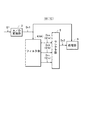
測定装置1は、図1に示すように、レンジ切換部2、A/D変換部3、フィルタ部4、セレクタ部5、処理部6および表示部7を備え、入力した測定対象信号Siの電気的パラメータ(実効値や平均値など)Pを測定可能に構成されている。
As shown in FIG. 1, the measuring
レンジ切換部2は、例えば、アンプやアッテネータを有して構成されて、外部から入力した測定対象信号Siを増幅して、増幅された測定対象信号S1として出力する。具体的には、レンジ切換部2は、測定対象信号Siに対する増幅率を処理部6から指定された測定レンジに対応した増幅率に変更可能に構成され、変更した増幅率で測定対象信号Siを増幅することにより、後段のA/D変換部3の入力電圧範囲内において予め規定された電圧範囲内に信号レベルが含まれる測定対象信号S1に変換して出力する。A/D変換部3は、レンジ切換部2から出力される測定対象信号S1を入力すると共に、予め規定されたサンプリングクロックに同期して測定対象信号S1をサンプリングすることにより、測定対象信号S1の瞬時値(電圧値)を示すデータDv1に変換して出力する。
For example, the
フィルタ部4は、減衰性能(一例として、減衰傾度)の異なる複数のデジタルフィルタで構成されている。本例では一例として、フィルタ部4は、直列に接続された3つのデジタルローパスフィルタ(LPF4a,LPF4b,LPF4c)、すなわち、測定対象信号S1を示すデータDv1を入力すると共にフィルタリング処理して新たな測定対象信号S1aを示すデータDvaとして出力する1段目のLPF4aと、この測定対象信号S1aを入力すると共にフィルタリング処理して新たな測定対象信号S1bとして出力する2段目のLPF4bと、この測定対象信号S1bを入力すると共にフィルタリング処理して新たな測定対象信号S1cとして出力する3段目のLPF4cとを備えている。
The
このフィルタ部4では、1段目のLPF4aが減衰性能の異なる1つのフィルタ(初段目のフィルタ)として機能して、測定対象信号S1を示すデータDv1に対してフィルタリング処理して、新たな測定対象信号S1aを示すデータDvaを出力する。また、1段目および2段目のLPF4a,4bが全体として減衰性能の異なる他の1つのフィルタ(2段目のフィルタ)として機能して、測定対象信号S1を示すデータDv1に対してフィルタリング処理(データDv1に含まれているノイズ(リップル)成分を上記の初段目のフィルタよりも多く除去するフィルタリング処理)して、新たな測定対象信号S1bを示すデータDvbを出力する。
In this
また、1段目、2段目および3段目のLPF4a,4b,4cが全体として減衰性能の異なる他の1つのフィルタ(3段目のフィルタ)として機能して、測定対象信号S1を示すデータDv1に対してフィルタリング処理(データDv1に含まれているノイズ(リップル)成分を上記の2段目のフィルタよりも多く除去するフィルタリング処理)して、新たな測定対象信号S1cを示すデータDvcを出力する。このフィルタ部4によれば、複数のLPF4a,LPF4b,LPF4cを多段に直列に接続して、LPF4aを初段目のフィルタとして、LPF4aおよびLPF4bを2段目のフィルタとして、LPF4a,LPF4b,LPF4cを3段目のフィルタとして機能させることにより、例えば、各LPF4a,LPF4b,LPF4cを同型のフィルタ(例えば、同じ次数のフィルタ)で構成したとしても、減衰性能の異なる複数(本例では3つ)のフィルタを構成することが可能となっている。また、上記の初段目、2段目および3段目の各フィルタは、上記したようにこの順でフィルタとしての機能(通過域外の周波数成分(ノイズ)の除去機能)が向上するものの、一般的に次数がこの順で大きくなるため、ステップ状に変化するデータDv1に対する応答性(ステップ応答性)はこの順に低下する。
The first-stage, second-stage, and third-
セレクタ部5は、測定対象信号S1を示すデータDv1、測定対象信号S1aを示すデータDva、測定対象信号S1bを示すデータDvb、および測定対象信号S1cを示すデータDvcを入力すると共に、これらのデータDv1,DVa,Dvb,Dvcのうちの処理部6によって選択された1つのデータを選択データDv2(選択された1つの測定対象信号S1のデータ)として出力する。
The
処理部6は、CPUおよびメモリ(いずれも図示せず)を備えて構成されて、レンジ切換部2に対するレンジ切換制御、およびセレクタ部5に対する信号(データ)選択制御を実行する。また、処理部6は、第1処理、第2処理および第3処理を実行する。これらの各処理時において、処理部6は、セレクタ部5に対してデータDv1,DVa,Dvb,Dvcのうちの予め規定されたデータを選択データDv2として出力させると共に、この選択データDv2およびレンジ切換部2での増幅率に基づいてこの選択データDv2として出力されるデータに対応する測定対象信号Siについての電気的パラメータPを算出する。また、処理部6は、少なくとも第1処理および第2処理では、電気的パラメータPと共に電気的パラメータPの変動率についても算出し、この変動率と予め規定された基準値とを比較する。また、処理部6は、少なくとも第1処理および第3処理では、算出した電気的パラメータPを表示部7に表示させる表示処理を実行する。メモリには、算出した変動率に対する上記した基準値が予め記憶されている。
The
次いで、測定装置1による測定対象信号Siについての電気的パラメータPの測定動作について説明する。一例として、電気的パラメータPとして実効値Drmsを測定する例を挙げて説明する。
Next, the measurement operation of the electrical parameter P for the measurement target signal Si by the
測定装置1では、処理部6は、セレクタ部5から出力される選択データDv2およびレンジ切換部2での増幅率に基づいて、測定対象信号Siの実効値Drmsを算出している。また、処理部6は、実効値Drmsの変動率(本例では、最新値とその直前の値との差分を最新値で除算した値の絶対値)を算出して、基準値と比較している。この基準値については、本例では一例として、測定対象信号Siの信号レベル(具体的には、算出している測定対象信号Siの実効値Drms)が現在の測定レンジ内でのみ変動する状態にあるとき、つまり、レンジ切換部2から出力されている測定対象信号S1の信号レベルが、A/D変換部3に対して予め規定された上記の電圧範囲内でのみ変動する状態にあるときには、算出している実効値Drmsの変動率が基準値以下となるように予め規定されている。
In the measuring
まず、処理部6によって測定対象信号Siに対する適切な測定レンジが特定され、レンジ切換部2が処理部6から指定された増幅率(この特定した測定レンジに対応する増幅率)で測定対象信号Siを増幅している状態においては、測定対象信号Siは現在の測定レンジ内で変動する状態にあり、これにより、処理部6によって算出される実効値Drmsも現在の測定レンジ内でのみ変動する状態にある。したがって、実効値Drmsの変動率は基準値以下となる。このため、フィルタ部4でのステップ応答性を低下させたとしても、測定対象信号Siの変動に十分に追従して実効値Drmsを算出可能であることから、フィルタ部4から出力される各データDva,Dvb,Dvcのうちの最もノイズ成分の少ないデータDvcを使用して実効値Drmsを高精度で算出し得る状態にある。この状態においては、処理部6は、第1処理を実行する。
First, an appropriate measurement range for the measurement target signal Si is specified by the
この第1処理では、処理部6は、レンジ切換部2に対するレンジ切換制御として、現在の測定レンジを維持させる制御を実行する。また、処理部6は、セレクタ部5に対する信号選択制御として、フィルタ部4から出力される各データDva,Dvb,Dvcのうちの最もノイズ成分の少ないデータDvcを選択データDv2として出力させる信号選択制御を実行する。また、処理部6は、この選択データDv2に基づいて実効値Drmsを算出すると共に、実効値Drmsの変動率を算出する。この場合、処理部6は、セレクタ部5から選択データDv2が出力される都度、この1つの選択データDv2に基づいて実効値Drmsを算出する構成を採用することもできるし、またこの選択データDv2に対する区間平均値を算出して、この区間平均値に基づいて実効値Drmsを算出する構成を採用することもできる。この区間平均値を算出する際の平均化区間としては、ハムノイズを除去するため、例えば商用周波数の1周期よりも長い区間(一例として100ms)に規定される。本例の測定装置1では、後者の構成を採用して、処理部6が、この平均化区間毎に選択データDv2の区間平均値を算出し、この区間平均値に基づいて実効値Drmsを算出する。
In the first processing, the
また、処理部6は、この第1処理時において実効値Drmsを算出したときには、表示処理を実行して、算出した実効値Drmsを表示部7に表示させる。この構成により、測定装置1では、測定対象信号Siの実効値Drmsが現在の測定レンジ内でのみ変動する状態にあるときには、表示部7には、平均化区間の時間間隔(本例では100ms間隔)で、測定対象信号Siについての実効値Drmsが更新されつつ表示される。したがって、この測定装置1を用いた測定対象信号Siの実効値Drmsについての測定が可能となっている。
Further, when the effective value Drms is calculated in the first process, the
一方、処理部6は、上記した第1処理の実行中に、測定対象信号Siの信号レベルが変動して、算出している実効値Drmsが現在の測定レンジ外となったとき(つまり、レンジ切換部2から出力されている測定対象信号S1の信号レベルが、A/D変換部3に対して予め規定された上記の電圧範囲を外れたとき)には、現在の測定レンジに隣接して予め規定された測定レンジのうちの実効値Drmsの変化方向に隣接する測定レンジを選択すると共に、レンジ切換部2に対するレンジ切換制御を実行して、レンジ切換部2での増幅率を選択した測定レンジに対応する増幅率に変更する(レンジ切換を行う)。
On the other hand, the
レンジ切換制御の実行時には、レンジ切換部2での測定対象信号Siに対する増幅率がステップ的に変更されるため、レンジ切換部2から出力される測定対象信号S1の信号レベルもステップ的に大きく変動(変化)して、実効値Drmsの変動率が上記の基準値を超える状態となる。また、このレンジ切換制御の実行時には、測定対象信号S1についての信号レベルの変動に対して、可能な限り遅延の少ない状態で追従して測定対象信号Siの実効値Drmsを算出することにより、この算出した実効値Drmsが含まれる測定レンジ(つまり、測定対象信号Siに対する測定レンジ)をできる限り迅速に特定するのが好ましい。したがって、処理部6は、レンジ切換制御の実行に起因して実効値Drmsの変動率が基準値を超えるときには、応答性の最も低い3段目のフィルタから出力されるデータDvcを使用する第1処理を中止して、第2処理を実行する。
When the range switching control is executed, the amplification factor for the measurement target signal Si in the
この第2処理では、処理部6は、算出している実効値Drmsが含まれる測定レンジを特定するレンジング動作を実行する。この際、処理部6は、算出している実効値Drmsが新たに選択した測定レンジ外となるときには、実効値Drmsの変化方向に測定レンジを順次切り替えるレンジ切換制御についても併せて実行する。また、処理部6は、算出している実効値Drmsが含まれる最終的な測定レンジをできる限り迅速に特定するため、セレクタ部5に対する信号選択制御を実行して、フィルタリング処理が行われていないデータDv1を選択データDv2としてセレクタ部5から出力させる。これにより、処理部6は、測定対象信号Siの変動に対する遅延の少ない状態(フィルタ部4から出力されるデータDva,Dvb,Dvcのうちのいずれかを使用するときよりも確実に遅延の少ない状態)で測定対象信号Siの実効値Drmsを算出する。
In the second process, the
これにより、処理部6は、測定対象信号Siに対する適切な測定レンジ、つまり算出している実効値Drmsが含まれる最終的な測定レンジを迅速に(高速に)特定する。なお、このレンジング動作中に算出される実効値Drmsについては、表示部7に表示させることもできるが、測定対象信号Siに生じている本来の変動だけでなく、測定レンジの切り換え動作(レンジング動作)に伴う変動も含まれているため、正確なものではない。このため、処理部6は、レンジング動作中は、算出した実効値Drmsの表示部7への表示は行わず、例えば、レンジング動作中を示す記号などを表示部7に表示させる。なお、このレンジング動作中において、選択データDv2として出力されるデータDv1に基づいて実効値Drmsを算出するときの平均化区間を、第1処理や第3処理時において実効値Drmsを算出するときの平均化区間(100ms)よりも短縮する(例えば、10msにする)ことにより、一層遅延の少ない状態で実効値Drmsを算出する構成とすることもできる。
As a result, the
その後に、測定対象信号Siの信号レベルの変動が小さくなり、この結果、算出している実効値Drmsの変動も小さくなったときには、測定対象信号Si(具体的には、その実効値Drms)は所定の測定レンジ内でのみ変動する状態となる。このため、処理部6は、この測定レンジを最終的な測定レンジ(適切な測定レンジ)として特定する。また、このようにして、実効値Drmsの変動が小さくなった(収束した)ときには、算出している実効値Drmsの変動率は基準値以下となる(変動率が基準値以下に戻る)。このため、処理部6は、レンジ切換部2に対するレンジ切換制御を停止して(測定レンジを固定して)第2処理を終了し、次いで、第1処理の実行を再開する前処理として第3処理を実行する。
Thereafter, when the fluctuation of the signal level of the measurement target signal Si is reduced, and as a result, the fluctuation of the calculated effective value Drms is also reduced, the measurement target signal Si (specifically, its effective value Drms) is The state fluctuates only within a predetermined measurement range. Therefore, the
この第3処理では、処理部6は、実効値Drmsを算出するための平均化区間を第1処理のときと同じ平均化区間(100ms)に戻し、第2処理時において選択データDv2としてセレクタ部5から出力されているデータDv1(フィルタリング処理が行われていないデータDv1)に基づいて実効値Drmsを算出して表示部7に表示させ、その後に、セレクタ部5に対する信号選択制御を実行して、1段目、2段目および3段目の各ローパスフィルタから出力されるデータDva,Dvb,Dvcをこの順に(減衰性能の低いローパスフィルタ側から順次)セレクタ部5から一定の時間間隔(例えば、100msの平均化区間)で切り換えて選択データDv2として出力させる。また、処理部6は、選択データDv2として出力される各データDva,Dvb,Dvcに基づいて実効値Drmsをそれぞれ算出して、表示部7に順次表示させる。これにより、第3処理が完了する。第3処理の完了時点では、各データDv1,Dva,Dvb,Dvcのうちの最もノイズ成分の少ないデータDvcを使用して算出された実効値Drmsが表示部7に表示される。
In the third process, the
第3処理の完了後に、処理部6は、第1処理を再開する。これにより、処理部6は、新たに特定した測定レンジにおいて、引き続き、最もノイズ成分の少ないデータDvcを使用して実効値Drmsを高精度で算出して、表示部7に表示させる。
After the completion of the third process, the
このように、この測定装置1では、フィルタ部4が、減衰性能の異なる複数のローパスフィルタ(1段目、2段目および3段目の各ローパスフィルタ)を有し、入力した測定対象信号S1のデータDv1に対してフィルタリング処理を行って、データDva,Dvb,Dvcを出力し、セレクタ部5が、フィルタリング処理が行われていないデータDv1、およびフィルタ部4でフィルタリング処理が行われた各データDva,Dvb,Dvcを入力すると共に、これらのデータDv1,Dva,Dvb,Dvcのうちから処理部6によって選択された1つのデータDvを選択データDv2として出力する。
Thus, in this
したがって、この測定装置1によれば、処理部6は、算出した測定対象信号Siの実効値Drmsが現在の測定レンジ(選択している測定レンジ)内で変化しているときのように、この実効値Drmsの変動率が基準値以下のときには、セレクタ部5に対する信号選択制御を実行して、減衰性能の最も高い3段目の各ローパスフィルタからのデータDvc(LPF4cからのデータ)を出力させ、このデータDvcに基づいて実効値Drmsを算出する第1処理を実行することにより、測定対象信号Siの実効値Drmsを高精度で測定することができる。
Therefore, according to the
また、この測定装置1では、処理部6は、算出した測定対象信号Siの実効値Drmsが現在の測定レンジ(選択している測定レンジ)外となってレンジ切換が行われたときのように、この実効値Drmsの変動率が基準値を超えたときには、第1処理を終了して第2処理を実行し、この第2処理時において、セレクタ部5からフィルタリング処理が行われていない(応答性の高い)データDv1を出力させ、このデータDv1に基づいて実効値Drmsを算出する。したがって、この測定装置1によれば、レンジング動作時に生じる測定対象信号S1の大きな変動に対する実効値Drmsの算出までの応答時間を短くすることができるため(測定対象信号S1の大きな変動に対する応答性を高めることができるため)、算出している実効値Drmsが含まれる測定レンジを特定することにより、測定対象信号Siの信号レベルが含まれる測定レンジを迅速に(高速に)特定することができる。
Moreover, in this
また、この測定装置1では、処理部6は、第2処理時において算出している測定対象信号Siの実効値Drmsが現在の測定レンジ(選択している測定レンジ)内だけで変動するようになったときのように、第2処理での実効値Drmsの変動率が基準値以下に戻ったときには、第2処理を終了して、第1処理の実行を再開する前処理として第3処理を実行する。処理部6は、この第3処理時において、まず、選択データDv2としてセレクタ部5から出力されてるデータDv1に基づいて、平均化区間を100msとして実効値Drmsを算出して表示部7に表示させる。その後、処理部6は、セレクタ部5に対する信号選択制御を実行して、複数のローパスフィルタ(1段目、2段目および3段目の各ローパスフィルタ)から出力されるデータDva,Dvb,Dvcを減衰性能の低い1段目のローパスフィルタ(LPF4a)側のデータDvaから、データDva,Dvb,Dvcの順に選択データDv2として順次出力させると共に平均化区間を100msとして実効値Drmsを算出して表示させる。
Further, in the
したがって、この測定装置1によれば、応答性重視の実効値Drmsの測定から精度重視の実効値Drmsの測定に順次移行させつつ実効値Drmsを表示することができ、この結果、データDv1に基づく実効値Drmsから、データDvaに基づく実効値Drms、データDvbに基づく実効値Drms、データDvcに基づく実効値Drmsの順に、実効値Drmsに含まれているノイズ成分の影響を段階的に低減しつつ滑らかに切り換えながら表示部7に実効値Drmsを表示させることができる。
Therefore, according to the measuring
また、この測定装置1によれば、セレクタ部5に対する制御を実行して、減衰特性の異なる複数のローパスフィルタ、つまり、1段目のローパスフィルタ(LPF4a)、2段目のローパスフィルタ(LPF4aとLPF4b)、および3段目のローパスフィルタ(LPF4aとLPF4bとLPF4c)からそれぞれ出力されるデータDva,Dvb,Dvcを切り換える(ローパスフィルタを切り換える)構成を採用したことにより、フィードバック系の関数で表されるフィルタの演算式の係数を変更してフィルタ自体の減衰特性を変更する構成(背景技術で説明した発明の構成)とは異なり、フィルタの減衰特性の変更に伴う不安定動作の発生を回避することができる。
Further, according to the measuring
なお、上記の測定装置1では、直列に接続した同型のLPF4a,4b,4cでフィルタ部4を構成し、かつ1段目のLPF4a、1段目および2段目のLPF4a,4b、並びに1段目〜3段目のLPF4a,4b,4cでそれぞれ1つのローパスフィルタを構成することにより、例えば設計に要する作業人員や作業時間(手間)を省いて減衰性能の異なる複数(本例では3つ)のローパスフィルタを構成しているが、この構成に限られない。例えば、図2に示す測定装置1Aのフィルタ部4Aのように、フィルタ部4Aを構成する複数のローパスフィルタ(本例では一例として3つのLPF14a,14b,14c)をそれぞれ減衰性能の異なる異型のフィルタ(例えば次数の異なるフィルタ)として構成することもできる。本例では、LPF14a,14b,14cの順に減衰性能が高まるものとする。このフィルタ部4Aでは、データDv1を各LPF14a,14b,14cにそれぞれ入力して、各LPF14a,14b,14cからの出力を、データDva,Dvb,Dvcとしてセレクタ部5に出力する。なお、測定装置1の構成と同一の構成については同一の符号を付して重複する説明を省略する。
In the
この測定装置1Aにおいても、フィルタ部4Aが減衰性能の異なる複数のローパスフィルタ(LPF14a,LPF14b,LPF14c)を有し、入力した測定対象信号S1のデータDv1に対して各LPF14a,LPF14b,LPF14cがそれぞれフィルタリング処理を行って、データDva,Dvb,Dvcを出力し、セレクタ部5が、フィルタリング処理が行われていないデータDv1、およびフィルタリング処理が行われた各データDva,Dvb,Dvcを入力すると共に、これらのデータDv1,Dva,Dvb,Dvcのうちから処理部6によって選択された1つのデータDvを選択データDv2として出力する。したがって、測定装置1Aも、上記した測定装置1と同様の効果を奏することができる。
Also in this
また、上記の測定装置1,1Aでは、処理部6は、セレクタ部5から出力される選択データDv2に基づいて算出した測定対象信号Siについての実効値Drmsの変動率が基準値以下か、基準値を超えるかに基づいて、第1処理を実行するか、第1処理を終了して第2処理を実行するか(第2処理に移行するか)、第2処理を終了して第3処理を実行するか(第3処理に移行するか)を特定しているが、この構成に限られない。
In the
例えば、上記の測定装置1,1Aでは、基準値について、処理部6によって算出される実効値Drmsが現在の測定レンジ内でのみ変動する状態にあるときには、算出している実効値Drmsの変動率が基準値以下となり、かつ処理部6によってレンジ切換部2に対するレンジ切換制御が実行され、これによってレンジ切換部2から出力される測定対象信号S1の信号レベルがステップ的に大きく変動(変化)したときに、その変動率が基準値を超える状態となるように予め設定されている。このため、上記の測定装置1,1Aでは、実効値Drmsの変動率が基準値以下となることと、実効値Drmsが現在の測定レンジ内だけで変動する状態にあることが等価な状態となっており、また実効値Drmsの変動率が基準値を超えることと、実効値Drmsが現在の測定レンジ外となることが等価な状態となっている。
For example, in the
したがって、上記の測定装置1,1Aにおいて、実効値Drmsの変動率を基準値と比較する構成に代えて、選択している測定レンジと実効値Drmsとを比較する構成を採用して、処理部6によって算出される実効値Drmsが現在の測定レンジ内だけで変動する状態か否か(測定レンジ外となったか否か)に基づいて、第1処理を実行するか、第1処理を終了して第2処理を実行するか、第2処理を終了して第3処理を実行するかを特定する構成を採用することもできる。この構成を採用することにより、処理部6による実効値Drmsの変動率の算出処理を不要にできるため、処理部6に対する負荷を軽減することができる。
Therefore, in the above-described
また、上記の測定装置1,1Aでは、上記したように、実効値Drmsの変動率が基準値以下となることと、実効値Drmsが現在の測定レンジ内だけで変動する状態にあることが等価な状態となり、また実効値Drmsの変動率が基準値を超えることと、実効値Drmsが現在の測定レンジ外となることが等価な状態となるように、この基準値が規定されているが、基準値をより小さくすることもできる。
In the
このように構成することにより、1つの測定レンジ内で実効値Drmsが変動している状態においても(つまり、レンジ切換が行われない状態においても)、測定対象信号Siがある程度大きく変動したときには、実効値Drmsの変動率が基準値を超える状態にすることができる。このため、この構成においては、処理部6は、レンジ切換のときのような大きな変動が測定対象信号Siに生じた場合だけでなく、1つの測定レンジ内で測定対象信号Siが予め規定された量よりも大きく変動した場合(ある程度大きく変動した場合)にも、第1処理の実行を停止して、第2処理を実行する。また、処理部6は、この第2処理の実行の際に、1つの測定レンジ内での測定対象信号Siの変動に起因して実効値Drmsの変動率が基準値を超える状態となったとき(つまり、レンジ切換を伴わずに実効値Drmsの変動率が基準値を超える状態となったとき)には、処理部6は、第2処理時において、セレクタ部5からフィルタリング処理が行われていない(応答性の高い)データDv1を出力させ、このデータDv1に基づいて実効値Drmsを算出した際に、この実効値Drmsを表示部7に表示させる。
With this configuration, even when the effective value Drms fluctuates within one measurement range (that is, even when the range is not switched), when the measurement target signal Si fluctuates to some extent, The fluctuation rate of the effective value Drms can exceed the reference value. For this reason, in this configuration, the
したがって、この構成によれば、1つの測定レンジ内で信号レベルがある程度大きく変動する測定対象信号Siの実効値Drmsについても、応答性の良好な状態で算出して表示部7に表示させることができる。
Therefore, according to this configuration, the effective value Drms of the measurement target signal Si whose signal level fluctuates to some extent within one measurement range can also be calculated and displayed on the
また、上記した各測定装置1,1Aでは、処理部6は、セレクタ部5から出力される選択データDv2に基づいて算出した実効値Drmsを用いて、その変動率が基準値以下であるか否かの判別、実効値Drmsが現在の測定レンジ外になるか否かの判別、および測定レンジの特定を実行する構成を採用しているが、例えば、図3,4に示す測定装置1B,1Cのように、常時、フィルタリング処理が行われていない応答性の良好なデータDv1をセレクタ部5を介することなく(経由することなく)A/D変換部3から直接入力すると共に、このデータDv1に基づいて実効値Drmsを算出し、この実効値Drmsを用いて、その変動率が基準値以下であるか否かの判別や、実効値Drmsが現在の測定レンジ外になるか否かの判別や、測定レンジの特定をする構成を採用することもできる。
Further, in each of the measuring
以下、測定装置1B,1Cについて説明する。なお、セレクタ部5から出力される選択データDv2に基づいて算出した測定対象信号Siの電気的パラメータPである実効値Drmsと、A/D変換部3から直接入力したデータDv1(フィルタリング処理が行われていないデータDv1)に基づいて算出した測定対象信号Siの電気的パラメータPである実効値Drmsとを区別するため、本例では、前者の実効値Drmsについては、測定対象信号Siの第1電気的パラメータP(第1実効値Drms)といい、後者の実効値Drmsについては、測定対象信号Siの第2電気的パラメータ(第2実効値Drms)という。また、処理部6が、第2実効値Drmsに基づいて、その変動率が基準値以下であるか否かの判別などをする上記の構成を除く他の構成や動作については、測定装置1Bは測定装置1と同じであり、測定装置1Cは測定装置1Aと同じであるため、測定装置1,1Aと同一の構成については同一の符号を付して重複する説明を省略する。
Hereinafter, the measuring
この測定装置1B,1Cでは、処理部6は、A/D変換部3から直接入力しているデータDv1の第2実効値Drmsおよびこの第2実効値Drmsの変動率を算出しつつ、この変動率がこの変動率に対して予め規定された基準値以下であるか否かに基づいて(基準値以下であるか否かを判別して)、第1処理を実行するか、第1処理を終了して第2処理を実行するか、第2処理を終了して第3処理を実行するかを特定する。また、処理部6は、第1処理時において、第2実効値Drmsが現在の測定レンジ外になるか否かを判別し、第2処理時において、第2実効値Drmsに基づいて測定レンジを特定する。このため、この測定装置1B,1Cでは、第1実効値Drmsについての変動率と基準値との比較は不要なため、処理部6は、第1実効値Drmsについての変動率の算出は行わず、したがって、変動率と基準値との比較も行わない。
In the
また、処理部6は、選択データDv2に基づいて第1実効値Drmsを算出する際には、常に同じ平均化区間(100ms)で算出し、A/D変換部3から直接入力したデータDv1に基づく第2実効値Drmsの算出に際しては、選択データDv2に基づいて第1実効値Drmsを算出する際の平均化区間よりも十分に短い平均化区間(10ms)で常に実効値Drmsを算出する構成とする。
Further, when calculating the first effective value Drms based on the selection data Dv2, the
この構成により、この測定装置1B,1Cによれば、処理部6がA/D変換部3から直接入力した応答性の良好なデータDv1を使用し、かつ第1実効値Drmsを算出する際の平均化区間(100ms)よりも十分に短い平均化区間(10ms)で第2実効値Drmsを算出するため、処理部6は、上記測定装置1,1Aの処理部6が選択データDv2に基づいて第1実効値Drmsおよびその変動率を算出するのに要する時間よりも短時間で、第2実効値Drmsおよびその変動率を算出することができる(応答時間を短くすることができる)。
With this configuration, according to the
したがって、この測定装置1B,1Cによれば、上記した測定装置1,1Aによって奏される効果に加えて、第2実効値Drmsおよびその変動率に対する追従性(応答性)を一層高めることができる結果、処理部6は、第2実効値Drmsの変動率がこの第2実効値Drmsに対して規定された基準値以下か、この基準値を超えるかに基づいて、第1処理を実行するか、第1処理を終了して第2処理を実行するか、第2処理を終了して第3処理を実行するかを一層迅速に特定して、特定した処理へより短時間で移行することができる。また、この測定装置1B,1Cによれば、第2処理時において行われる第2実効値Drmsに基づく測定レンジの特定に要する応答時間についても、短縮することができる。
Therefore, according to the
また、この測定装置1B,1Cにおいても、第2実効値Drmsの変動率が基準値以下となることと、第2実効値Drmsが現在の測定レンジ内だけで変動する状態にあることが等価な状態となり、また第2実効値Drmsの変動率が基準値を超えることと、第2実効値Drmsが現在の測定レンジ外となることが等価な状態となるように、第2実効値Drmsについての基準値が規定されているときには、上記した測定装置1,1Aと同様にして、第2実効値Drmsの変動率をその基準値と比較する構成に代えて、処理部6が、第2実効値Drmsが現在の測定レンジ内だけで変動する状態か否か(測定レンジ外となったか否か)に基づいて、第1処理を実行するか、第1処理を終了して第2処理を実行するか、第2処理を終了して第3処理を実行するかを特定する構成を採用することもできる。この構成を採用することにより、処理部6による第2実効値Drmsの変動率の算出処理を不要にできるため、処理部6に対する負荷を軽減することができる。
Also in the
さらに、この測定装置1B,1Cにおいても、第2実効値Drmsに対する基準値をさらに小さくすることにより、上記した測定装置1,1Aのときと同様にして、1つの測定レンジ内で測定対象信号Siが予め規定された量よりも大きく変動した場合(ある程度大きく変動した場合)にも、処理部6が、第1処理の実行を停止して、第2処理を実行する構成とすることができる。したがって、この構成において、処理部6が第2処理を実行するときに、セレクタ部5から選択データDv2として出力されるフィルタリング処理が行われていない(応答性の高い)データDv1に基づいて実効値Drmsを算出した際に、この実効値Drmsを表示部7に表示させることにより、1つの測定レンジ内で信号レベルがある程度大きく変動する測定対象信号Siの実効値Drmsについても、応答性の良好な状態で算出して表示部7に表示させることができる。
Further, in the
また、上記の測定装置1B,1Cのように、セレクタ部5を介さずにA/D変換部3から直接入力したデータDv1に基づいて算出した第2実効値Drmsに基づいて、その変動率が基準値以下であるか否かの判別、第2実効値Drmsが現在の測定レンジ外になるか否かの判別、および測定レンジの特定を実行する構成においては、セレクタ部5に入力されて選択データDv2として出力されるデータDv1は、第3処理時において、最初に表示部7に表示させる第1実効値Drmsの算出のためにだけ使用される。このため、上記の測定装置1B,1Cにおいて、処理部6が、第3処理時において、選択データDv2として出力されるデータDv1に基づく第1実効値Drmsの算出および表示を省いて、データDvaに基づく第1実効値Drms、データDvbに基づく第1実効値Drms、データDvcに基づく第1実効値Drmsの順に第1実効値Drmsを算出して表示させる構成を採用する場合には、この構成の各測定装置1B(1C)においては、図5に示すように、A/D変換部3から出力されるデータDv1のセレクタ部5への入力を省き、フィルタ部4(4A)においてフィルタリング処理が行われたデータDva,Dvb,Dvcのみをセレクタ部5に入力する構成を採用することもできる。なお、図5では、説明に必要な構成のみを図示しているが、不図示の構成は図3,4に示す構成と同一である。
Further, as in the
また、図5に示す構成を採用した各測定装置1B(1C)において、第3処理時に、セレクタ部5を介さずにA/D変換部3から直接入力したデータDv1に基づいて、第2実効値Drmsと共に第1実効値Drmsを算出する構成とすることで、フィルタリング処理が行われていないデータDv1に基づく第1実効値Drmsを算出して表示させた後に、データDvaに基づく第1実効値Drms、データDvbに基づく第1実効値Drms、データDvcに基づく第1実効値Drmsの順に第1実効値Drmsを算出して表示させる構成とすることもできる。
Further, in each measuring
また、上記の測定装置1,1A,1B,1Cでは、フィルタ部4,4Aを一例として3つのLPF4a,LPF4b,LPF4cで構成しているが、フィルタ部4,4Aを構成するローパスフィルタの数は、3つに限定されず、2つ、4つなど、複数であれば任意の数とすることができる。また、セレクタ部5から出力される選択データDv2に基づいて算出する電気的パラメータPとして、実効値Drmsを算出する例について説明したが、本発明は、平均値などの種々の特性値を算出する測定装置に対しても適用することができる。
In the
また、上記の測定装置1,1A,1B,1Cでは、レンジ切換部2を備え、入力した測定対象信号Siに対する増幅率を測定レンジに対応して変更することにより、A/D変換部3に入力される測定対象信号S1の信号レベルを、A/D変換部3に対して予め規定された電圧範囲内に含まれるようにしているが、測定対象信号Siの信号レベルの変動がこのA/D変換部3の電圧範囲内に常に含まれるものであるときには、レンジ切換部2を省く構成(測定レンジが単一の構成)とすることもできる。
In addition, the measuring
この構成の測定装置では、測定対象信号S1として測定対象信号SiがA/D変換部3に入力される。また、この測定装置では、上記した測定装置1,1A(1B,1C)において、1つの測定レンジ内で測定対象信号Siが変動している状態において、測定対象信号Siの変動が小さいときには、測定対象信号Siの実効値Drms(第2実効値Drms)の変動率が基準値以下となり、測定対象信号Siの変動がある程度大きいときには、実効値Drms(第2実効値Drms)の変動率が基準値を超えるように、基準値を予め規定する。また、測定対象信号Siの変動要因には、レンジ切換の要因が含まれていないため、処理部6は、第2処理時において、セレクタ部5からフィルタリング処理が行われていない(応答性の高い)データDv1を出力させ、このデータDv1に基づいて実効値Drmsを算出した際に、この実効値Drmsを表示部7に表示させる。
In the measurement apparatus having this configuration, the measurement target signal Si is input to the A /
これにより、この測定装置によれば、測定対象信号Siについての実効値Drms(第2実効値Drms)の変動率が基準値以下のときには、処理部6が、第1処理時において、データDv1,Dva,Dvb,DvcのうちのデータDvcをセレクタ部5から選択データDv2として出力させ、このデータDvcに基づいて実効値Drmsを算出して表示部7に表示させるため、測定対象信号Siの実効値Drmsを高精度で測定することができる。
Thereby, according to this measuring apparatus, when the variation rate of the effective value Drms (second effective value Drms) for the measurement target signal Si is equal to or less than the reference value, the
また、測定対象信号Siについての実効値Drms(第2実効値Drms)の変動率が基準値を超えているときには、処理部6は、第2処理時において、データDv1,Dva,Dvb,Dvcのうちのフィルタリング処理が行われていない(応答性の高い)データDv1をセレクタ部5から選択データDv2として出力させ、この選択データDv2に基づいて実効値Drms(第2実効値Drms)を算出して表示部7に表示させるため、1つの測定レンジ内で信号レベルがある程度大きく変動する測定対象信号Siの実効値Drms(第1実効値Drms)についても、応答性の良好な状態で算出して表示部7に表示させることができる。
Further, when the variation rate of the effective value Drms (second effective value Drms) for the measurement target signal Si exceeds the reference value, the
また、この測定装置によれば、第2処理後の第3処理時において、セレクタ部5に対する信号選択制御を実行して、データDv1,Dva,Dvb,Dvcの順にセレクタ部5から選択データDv2として出力させる実効値Drms(第1実効値Drms)を算出して表示させるため、実効値Drms(第1実効値Drms)に含まれているノイズ成分の影響を段階的に低減しつつ滑らかに切り換えながら表示部7に実効値Drms(第1実効値Drms)を表示させることができる。
Further, according to this measuring apparatus, during the third process after the second process, the signal selection control for the
また、上記の各測定装置1,1A,1B,1Cでは、処理部6は、選択データDv2に基づいて算出した実効値Drms(第1実効値Drms)を表示部7に表示させることで、この実効値Drms(第1実効値Drms)を直ちに確認し得る構成を採用しているが、この構成に限らず、表示部7に代えて記憶装置を備え、この記憶装置に実効値Drms(第1実効値Drms)を記憶させる構成を採用することもできるし、また外部機器とデータの受け渡しを行う送受信部を備え、この送受信部を介して外部機器に実効値Drms(第1実効値Drms)を出力する構成を採用することもできる。
Further, in each of the
1,1A,1B,1C 測定装置
4,4A フィルタ部
4a,4b,4c,14a,14b,14c LPF
5 セレクタ部
6 処理部
7 表示部
Drms 実効値
P 電気的パラメータ
S1,Si 測定対象信号
1, 1A, 1B,
5
Claims (5)
前記フィルタリング処理が行われていない前記測定対象信号および前記フィルタリング処理が行われた前記各測定対象信号を入力すると共に、当該測定対象信号のうちから選択された1つの測定対象信号を出力するセレクタ部と、
選択して前記セレクタ部から出力させた前記測定対象信号に基づいて当該測定対象信号の電気的パラメータおよび当該電気的パラメータの変動率を算出すると共に当該変動率と予め規定された基準値とを比較する処理部とを備え、
前記処理部は、前記変動率が前記基準値以下のときには第1処理を実行し、当該第1処理時において、選択して前記セレクタ部から出力させた前記減衰性能の最も高いローパスフィルタからの前記測定対象信号に基づいて前記電気的パラメータおよび前記変動率を算出し、前記変動率が前記基準値を超えるときには第2処理を実行し、当該第2処理時において、選択して前記セレクタ部から出力させた前記フィルタリング処理が行われていない前記測定対象信号に基づいて前記電気的パラメータおよび前記変動率を算出し、その後に前記変動率が前記基準値以下に戻ったときには前記第1処理を実行する前処理として第3処理を実行し、当該第3処理時において、前記複数のローパスフィルタから出力される前記測定対象信号を前記減衰性能の低いローパスフィルタ側から順次選択して前記セレクタ部から出力させると共に当該測定対象信号に基づいて前記電気的パラメータおよび前記変動率を算出する測定装置。 A filter unit that has a plurality of low-pass filters having different attenuation performances and that each low-pass filter performs a filtering process on the input measurement target signal; and
A selector unit that inputs the measurement target signal not subjected to the filtering process and the measurement target signals subjected to the filtering process and outputs one measurement target signal selected from the measurement target signals When,
Based on the measurement target signal selected and output from the selector unit, the electrical parameter of the measurement target signal and the variation rate of the electrical parameter are calculated, and the variation rate is compared with a predetermined reference value. And a processing unit to
The processing unit executes a first process when the variation rate is equal to or less than the reference value, and the first low-pass filter having the highest attenuation performance selected and output from the selector unit at the time of the first process. The electrical parameter and the variation rate are calculated based on the measurement target signal, and when the variation rate exceeds the reference value, a second process is executed, and in the second process, selected and output from the selector unit. The electrical parameter and the variation rate are calculated based on the measurement target signal that has not been subjected to the filtering process, and the first processing is executed when the variation rate subsequently returns to the reference value or less. A third process is executed as a pre-process, and the measurement target signals output from the plurality of low-pass filters are converted into the attenuation performance during the third process. Measuring device for calculating the electrical parameter and the variation rate based on the measured signal with sequentially selects from low pass filter side is outputted from the selector unit.
減衰性能の異なる複数のローパスフィルタを有すると共に前記レンジ切換部から出力された前記測定対象信号に対して当該各ローパスフィルタがそれぞれフィルタリング処理を行って出力するフィルタ部と、
前記レンジ切換部からの前記フィルタリング処理が行われていない前記測定対象信号、および前記フィルタリング処理が行われた前記各測定対象信号を入力すると共に、当該測定対象信号のうちから選択された1つの測定対象信号を出力するセレクタ部と、
選択した前記測定レンジに対応した前記増幅率で前記レンジ切換部に対して前記測定対象信号を増幅させ、かつ選択して前記セレクタ部から出力させた前記測定対象信号に基づいて前記レンジ切換部に入力される前記測定対象信号の電気的パラメータを算出すると共に当該電気的パラメータと前記選択した測定レンジとを比較する処理部とを備え、
前記処理部は、前記電気的パラメータが前記選択した測定レンジ内で変化しているときには第1処理を実行し、当該第1処理時において、選択して前記セレクタ部から出力させた前記減衰性能の最も高いローパスフィルタからの前記測定対象信号に基づいて前記電気的パラメータを算出し、前記電気的パラメータが前記選択した測定レンジ外となったときには第2処理を実行し、当該第2処理時において、選択して前記セレクタ部から出力させた前記フィルタリング処理が行われていない前記測定対象信号に基づく前記電気的パラメータの算出および前記レンジ切換部における前記増幅率の選択を実行しつつ当該電気的パラメータが含まれる測定レンジを特定し、当該測定レンジを特定した後には前記第1処理を実行する前処理として第3処理を実行し、当該第3処理時において、前記複数のローパスフィルタから出力される前記測定対象信号を前記減衰性能の低いローパスフィルタ側から順次選択して前記セレクタ部から出力させると共に当該測定対象信号に基づいて前記電気的パラメータを算出する測定装置。 A range switching unit for inputting the measurement target signal and amplifying the measurement target signal with an amplification factor corresponding to one measurement range selected from the plurality of measurement ranges;
A filter unit that has a plurality of low-pass filters having different attenuation performances, and that each low-pass filter performs a filtering process on the measurement target signal output from the range switching unit;
The measurement target signal not subjected to the filtering process from the range switching unit and each measurement target signal subjected to the filtering process are input, and one measurement selected from the measurement target signals A selector unit that outputs a target signal;
The range switching unit amplifies the measurement target signal to the range switching unit at the amplification factor corresponding to the selected measurement range, and selects and outputs the measurement target signal from the selector unit to the range switching unit. A processing unit that calculates an electrical parameter of the input measurement target signal and compares the electrical parameter with the selected measurement range;
The processing unit executes a first process when the electrical parameter changes within the selected measurement range, and selects the output of the attenuation performance selected and output from the selector unit during the first process. The electrical parameter is calculated based on the measurement target signal from the highest low-pass filter, and the second process is executed when the electrical parameter is out of the selected measurement range. The electrical parameter is calculated while performing the calculation of the electrical parameter based on the signal to be measured that has not been subjected to the filtering process selected and output from the selector unit, and the amplification factor is selected in the range switching unit. After the measurement range to be included is specified and the measurement range is specified, a third process is performed as a pre-process for executing the first process. In the third process, the measurement target signals output from the plurality of low-pass filters are sequentially selected from the low-pass filter side having low attenuation performance and output from the selector unit, and the measurement target signals are A measuring device for calculating the electrical parameter based on the measurement result.
前記フィルタリング処理が行われていない前記測定対象信号および前記フィルタリング処理が行われた前記各測定対象信号を入力すると共に、当該測定対象信号のうちから選択された1つの測定対象信号を出力するセレクタ部と、
選択して前記セレクタ部から出力させた前記測定対象信号に基づいて当該測定対象信号の第1電気的パラメータを算出し、かつ前記セレクタ部を介することなく入力した前記フィルタリング処理が行われていない前記測定対象信号の第2電気的パラメータおよび当該第2電気的パラメータの変動率を算出すると共に当該変動率と予め規定された基準値とを比較する処理部とを備え、
前記処理部は、前記変動率が前記基準値以下のときには第1処理を実行し、当該第1処理時において、選択して前記セレクタ部から出力させた前記減衰性能の最も高いローパスフィルタからの前記測定対象信号に基づいて前記第1電気的パラメータを算出し、前記変動率が前記基準値を超えるときには第2処理を実行し、当該第2処理時において、選択して前記セレクタ部から出力させた前記フィルタリング処理が行われていない前記測定対象信号に基づいて前記第1電気的パラメータを算出し、その後に前記変動率が前記基準値以下に戻ったときには前記第1処理を実行する前処理として第3処理を実行し、当該第3処理時において、前記複数のローパスフィルタから出力される前記測定対象信号を前記減衰性能の低いローパスフィルタ側から順次選択して前記セレクタ部から出力させると共に当該測定対象信号に基づいて前記第1電気的パラメータを算出する測定装置。 A filter unit that has a plurality of low-pass filters having different attenuation performances and that each low-pass filter performs a filtering process on the input measurement target signal; and
A selector unit that inputs the measurement target signal not subjected to the filtering process and the measurement target signals subjected to the filtering process and outputs one measurement target signal selected from the measurement target signals When,
The first electrical parameter of the measurement target signal is calculated based on the measurement target signal selected and output from the selector unit, and the filtering process input without going through the selector unit is not performed A processing unit that calculates the second electrical parameter of the measurement target signal and the variation rate of the second electrical parameter and compares the variation rate with a predetermined reference value;
The processing unit executes a first process when the variation rate is equal to or less than the reference value, and the first low-pass filter having the highest attenuation performance selected and output from the selector unit at the time of the first process. The first electrical parameter is calculated based on the measurement target signal, and the second process is executed when the variation rate exceeds the reference value, and is selected and output from the selector unit during the second process. The first electrical parameter is calculated based on the measurement target signal not subjected to the filtering process, and then the first process is performed as a pre-process when the variation rate returns to the reference value or less. 3 processing is performed, and the measurement target signal output from the plurality of low-pass filters at the time of the third processing is the low-pass filter side having a low attenuation performance Measuring device for calculating a first electrical parameter based on the measured signal together with al sequentially selected to be output from the selector unit.
減衰性能の異なる複数のローパスフィルタを有すると共に前記レンジ切換部から出力された前記測定対象信号に対して当該各ローパスフィルタがそれぞれフィルタリング処理を行って出力するフィルタ部と、
前記レンジ切換部からの前記フィルタリング処理が行われていない前記測定対象信号、および前記フィルタリング処理が行われた前記各測定対象信号を入力すると共に、当該測定対象信号のうちから選択された1つの測定対象信号を出力するセレクタ部と、
選択した前記測定レンジに対応した前記増幅率で前記レンジ切換部に対して前記測定対象信号を増幅させ、かつ選択して前記セレクタ部から出力させた前記測定対象信号に基づいて前記レンジ切換部に入力される前記測定対象信号の第1電気的パラメータを算出し、かつ前記セレクタ部を介することなく入力した前記フィルタリング処理が行われていない前記測定対象信号に基づいて前記レンジ切換部に入力される前記測定対象信号の第2電気的パラメータを算出すると共に当該第2電気的パラメータと前記選択した測定レンジとを比較する処理部とを備え、
前記処理部は、前記第2電気的パラメータが前記選択した測定レンジ内で変化しているときには第1処理を実行し、当該第1処理時において、選択して前記セレクタ部から出力させた前記減衰性能の最も高いローパスフィルタからの前記測定対象信号に基づいて前記第1電気的パラメータを算出し、前記第2電気的パラメータが前記選択した測定レンジ外となったときには第2処理を実行し、当該第2処理時において、選択して前記セレクタ部から出力させた前記フィルタリング処理が行われていない前記測定対象信号に基づく前記第1電気的パラメータの算出および前記レンジ切換部における前記増幅率の選択を実行しつつ前記第2電気的パラメータが含まれる前記測定レンジを特定し、当該測定レンジを特定した後には前記第1処理を実行する前処理として第3処理を実行し、当該第3処理時において、前記複数のローパスフィルタから出力される前記測定対象信号を前記減衰性能の低いローパスフィルタ側から順次選択して前記セレクタ部から出力させると共に当該測定対象信号に基づいて前記第1電気的パラメータを算出する測定装置。 A range switching unit for inputting the measurement target signal and amplifying the measurement target signal with an amplification factor corresponding to one measurement range selected from the plurality of measurement ranges;
A filter unit that has a plurality of low-pass filters having different attenuation performances, and that each low-pass filter performs a filtering process on the measurement target signal output from the range switching unit;
The measurement target signal not subjected to the filtering process from the range switching unit and each measurement target signal subjected to the filtering process are input, and one measurement selected from the measurement target signals A selector unit that outputs a target signal;
The range switching unit amplifies the measurement target signal to the range switching unit at the amplification factor corresponding to the selected measurement range, and selects and outputs the measurement target signal from the selector unit to the range switching unit. The first electrical parameter of the input measurement target signal is calculated, and input to the range switching unit based on the measurement target signal that has been input without going through the selector unit and has not been subjected to the filtering process A processing unit that calculates a second electrical parameter of the measurement target signal and compares the second electrical parameter with the selected measurement range;
The processing unit executes a first process when the second electrical parameter changes within the selected measurement range, and the attenuation selected and output from the selector unit during the first process. The first electrical parameter is calculated based on the measurement target signal from the low-pass filter having the highest performance, and when the second electrical parameter is out of the selected measurement range, a second process is executed, In the second process, the calculation of the first electrical parameter based on the measurement target signal that is selected and output from the selector unit is not performed, and the amplification factor is selected in the range switching unit. The measurement range including the second electrical parameter is specified while executing, and after the measurement range is specified, the first process is performed. A third process is executed as a pre-process, and at the time of the third process, the measurement target signals output from the plurality of low-pass filters are sequentially selected from the low-pass filter side having a low attenuation performance and output from the selector unit And a measuring device that calculates the first electrical parameter based on the signal to be measured.
前記フィルタリング処理が行われた前記各測定対象信号を入力すると共に、当該測定対象信号のうちから選択された1つの測定対象信号を出力するセレクタ部と、
選択して前記セレクタ部から出力させた前記測定対象信号に基づいて当該測定対象信号の第1電気的パラメータを算出し、かつ前記セレクタ部を介することなく入力した前記フィルタリング処理が行われていない前記測定対象信号の第2電気的パラメータおよび当該第2電気的パラメータの変動率を算出すると共に当該変動率と予め規定された基準値とを比較する処理部とを備え、
前記処理部は、前記変動率が前記基準値以下のときには第1処理を実行し、当該第1処理時において、選択して前記セレクタ部から出力させた前記減衰性能の最も高いローパスフィルタからの前記測定対象信号に基づいて前記第1電気的パラメータを算出し、前記変動率が前記基準値を超えるときには第2処理を実行し、当該第2処理時において、前記第1電気的パラメータについて前記セレクタ部から出力される前記測定対象信号に代えて前記セレクタ部を介することなく入力した前記フィルタリング処理が行われていない前記測定対象信号に基づいて算出し、その後に前記変動率が前記基準値以下に戻ったときには前記第1処理を実行する前処理として第3処理を実行し、当該第3処理時において、前記複数のローパスフィルタから出力される前記測定対象信号を前記減衰性能の低いローパスフィルタ側から順次選択して前記セレクタ部から出力させると共に当該測定対象信号に基づいて前記第1電気的パラメータを算出する測定装置。 A filter unit that has a plurality of low-pass filters having different attenuation performances and that each low-pass filter performs a filtering process on the input measurement target signal; and
A selector unit that inputs each of the measurement target signals subjected to the filtering process and outputs one measurement target signal selected from the measurement target signals;
The first electrical parameter of the measurement target signal is calculated based on the measurement target signal selected and output from the selector unit, and the filtering process input without going through the selector unit is not performed A processing unit that calculates the second electrical parameter of the measurement target signal and the variation rate of the second electrical parameter and compares the variation rate with a predetermined reference value;
The processing unit executes a first process when the variation rate is equal to or less than the reference value, and the first low-pass filter having the highest attenuation performance selected and output from the selector unit at the time of the first process. The first electrical parameter is calculated based on a signal to be measured, and when the rate of change exceeds the reference value, a second process is executed. During the second process, the selector unit for the first electrical parameter Calculation based on the measurement target signal that has not been subjected to the filtering process and is input without passing through the selector unit instead of the measurement target signal that is output from, and then the variation rate returns to the reference value or less. When the third process is executed, the third process is executed as a pre-process for executing the first process, and output from the plurality of low-pass filters during the third process. Measuring device for calculating a first electrical parameter based on the measured signal causes output from sequentially selected by the selector portion of the measurement object signal from the low pass filter side of the damping performance of.
Priority Applications (1)
| Application Number | Priority Date | Filing Date | Title |
|---|---|---|---|
| JP2011009458A JP2012150025A (en) | 2011-01-20 | 2011-01-20 | Measuring apparatus |
Applications Claiming Priority (1)
| Application Number | Priority Date | Filing Date | Title |
|---|---|---|---|
| JP2011009458A JP2012150025A (en) | 2011-01-20 | 2011-01-20 | Measuring apparatus |
Publications (1)
| Publication Number | Publication Date |
|---|---|
| JP2012150025A true JP2012150025A (en) | 2012-08-09 |
Family
ID=46792399
Family Applications (1)
| Application Number | Title | Priority Date | Filing Date |
|---|---|---|---|
| JP2011009458A Pending JP2012150025A (en) | 2011-01-20 | 2011-01-20 | Measuring apparatus |
Country Status (1)
| Country | Link |
|---|---|
| JP (1) | JP2012150025A (en) |
Cited By (6)
| Publication number | Priority date | Publication date | Assignee | Title |
|---|---|---|---|---|
| WO2016021575A1 (en) * | 2014-08-05 | 2016-02-11 | アルプス・グリーンデバイス株式会社 | Electric current sensor |
| JP2017053662A (en) * | 2015-09-08 | 2017-03-16 | 日置電機株式会社 | Measurement device |
| US20170108537A1 (en) * | 2013-03-15 | 2017-04-20 | Milwaukee Electric Tool Corporation | Digital multi-meter |
| JP2017083379A (en) * | 2015-10-30 | 2017-05-18 | 日置電機株式会社 | Impedance measuring apparatus and impedance measuring method |
| JP2017227518A (en) * | 2016-06-22 | 2017-12-28 | 日置電機株式会社 | Impedance measuring apparatus and impedance measuring method |
| JP2018036205A (en) * | 2016-09-01 | 2018-03-08 | 日置電機株式会社 | Impedance measuring apparatus and impedance measuring method |
Citations (9)
| Publication number | Priority date | Publication date | Assignee | Title |
|---|---|---|---|---|
| JPS63181872U (en) * | 1987-05-13 | 1988-11-24 | ||
| JPH01136016A (en) * | 1987-11-20 | 1989-05-29 | Mitsubishi Electric Corp | Analogue quantity measuring apparatus |
| JPH0530459A (en) * | 1991-07-23 | 1993-02-05 | Matsushita Electric Ind Co Ltd | Still image signal playback device |
| JPH0559993A (en) * | 1991-08-28 | 1993-03-09 | Hitachi Ltd | Control device for internal combustion engine |
| JPH06273453A (en) * | 1993-03-23 | 1994-09-30 | Yokogawa Electric Corp | AC signal measuring device |
| JPH0792200A (en) * | 1993-09-24 | 1995-04-07 | Miwa Denki Kk | Voltage / current recorder |
| JPH07111605A (en) * | 1993-10-14 | 1995-04-25 | Matsushita Electric Ind Co Ltd | Noise elimination circuit |
| JP2000002721A (en) * | 1998-05-08 | 2000-01-07 | Tektronix Inc | Digital multimeter, electronic measuring device, and automatic range function control method |
| JP2002055128A (en) * | 2000-08-11 | 2002-02-20 | Yokogawa Electric Corp | AC signal measuring instrument |
-
2011
- 2011-01-20 JP JP2011009458A patent/JP2012150025A/en active Pending
Patent Citations (9)
| Publication number | Priority date | Publication date | Assignee | Title |
|---|---|---|---|---|
| JPS63181872U (en) * | 1987-05-13 | 1988-11-24 | ||
| JPH01136016A (en) * | 1987-11-20 | 1989-05-29 | Mitsubishi Electric Corp | Analogue quantity measuring apparatus |
| JPH0530459A (en) * | 1991-07-23 | 1993-02-05 | Matsushita Electric Ind Co Ltd | Still image signal playback device |
| JPH0559993A (en) * | 1991-08-28 | 1993-03-09 | Hitachi Ltd | Control device for internal combustion engine |
| JPH06273453A (en) * | 1993-03-23 | 1994-09-30 | Yokogawa Electric Corp | AC signal measuring device |
| JPH0792200A (en) * | 1993-09-24 | 1995-04-07 | Miwa Denki Kk | Voltage / current recorder |
| JPH07111605A (en) * | 1993-10-14 | 1995-04-25 | Matsushita Electric Ind Co Ltd | Noise elimination circuit |
| JP2000002721A (en) * | 1998-05-08 | 2000-01-07 | Tektronix Inc | Digital multimeter, electronic measuring device, and automatic range function control method |
| JP2002055128A (en) * | 2000-08-11 | 2002-02-20 | Yokogawa Electric Corp | AC signal measuring instrument |
Cited By (8)
| Publication number | Priority date | Publication date | Assignee | Title |
|---|---|---|---|---|
| US20170108537A1 (en) * | 2013-03-15 | 2017-04-20 | Milwaukee Electric Tool Corporation | Digital multi-meter |
| US10126331B2 (en) * | 2013-03-15 | 2018-11-13 | Milwaukee Electric Tool Corporation | Digital multi-meter |
| WO2016021575A1 (en) * | 2014-08-05 | 2016-02-11 | アルプス・グリーンデバイス株式会社 | Electric current sensor |
| JPWO2016021575A1 (en) * | 2014-08-05 | 2017-04-27 | アルプス電気株式会社 | Current sensor |
| JP2017053662A (en) * | 2015-09-08 | 2017-03-16 | 日置電機株式会社 | Measurement device |
| JP2017083379A (en) * | 2015-10-30 | 2017-05-18 | 日置電機株式会社 | Impedance measuring apparatus and impedance measuring method |
| JP2017227518A (en) * | 2016-06-22 | 2017-12-28 | 日置電機株式会社 | Impedance measuring apparatus and impedance measuring method |
| JP2018036205A (en) * | 2016-09-01 | 2018-03-08 | 日置電機株式会社 | Impedance measuring apparatus and impedance measuring method |
Similar Documents
| Publication | Publication Date | Title |
|---|---|---|
| DK2660613T3 (en) | Method and module for measuring the frequency change rate of waveforms related to inverter units in wind turbine generators | |
| JP6486888B2 (en) | Operation control method of moving average filter | |
| CN108809272B (en) | Polynomial Kalman Filter Method and Filter | |
| WO2020024174A1 (en) | Method for acquiring frequency characteristics of servo system, and electronic apparatus and storage apparatus | |
| JP2000216664A (en) | Filter device and filter coefficient obtaining method thereof | |
| JP6314543B2 (en) | Method and apparatus for estimating state of charge of storage battery | |
| CN102124650A (en) | Signal processing circuit | |
| EP3267581A1 (en) | Filter generating device, filter generating method and filter generating program | |
| JP6739160B2 (en) | Impedance measuring device and impedance measuring method | |
| JP2013073630A (en) | Improved method and apparatus for eliminating aliasing | |
| US20170373699A1 (en) | Analog-To-Digital Converter Protection Circuit, Method for Controlling Analog-To-Digital Converter Protection Circuit, and Controller | |
| JP2012154763A (en) | Measuring apparatus and measuring method | |
| KR102286929B1 (en) | A method and a device for determining the current of an electric motor or generator | |
| JP5823800B2 (en) | Filter device, indicator and measuring device | |
| CN106255895B (en) | Electronic battery sensor and method for determining the internal resistance of a battery | |
| CN119716232A (en) | Current signal sampling circuit, method and battery system | |
| JP2001183408A (en) | Level measurement method corresponding to multiple measurement frequencies | |
| JP5958127B2 (en) | Analog input device | |
| CN113985340B (en) | Electric energy metering chip and phase compensation method and phase compensation device thereof | |
| US20160344371A1 (en) | Methods and devices for switching filters and medical apparatuses using the same | |
| JP5369944B2 (en) | Digital filter and material testing machine | |
| CN105656450A (en) | Digital lowpass filtering method and apparatus for integer arithmetic | |
| JP6292871B2 (en) | Power measuring device | |
| KR101567797B1 (en) | hybrid digital filter | |
| JP6380398B2 (en) | Digital processing apparatus and digital processing method |
Legal Events
| Date | Code | Title | Description |
|---|---|---|---|
| A621 | Written request for application examination |
Free format text: JAPANESE INTERMEDIATE CODE: A621 Effective date: 20131220 |
|
| A977 | Report on retrieval |
Free format text: JAPANESE INTERMEDIATE CODE: A971007 Effective date: 20140613 |
|
| A131 | Notification of reasons for refusal |
Free format text: JAPANESE INTERMEDIATE CODE: A131 Effective date: 20140701 |
|
| A521 | Written amendment |
Free format text: JAPANESE INTERMEDIATE CODE: A523 Effective date: 20140828 |
|
| A131 | Notification of reasons for refusal |
Free format text: JAPANESE INTERMEDIATE CODE: A131 Effective date: 20150127 |
|
| A02 | Decision of refusal |
Free format text: JAPANESE INTERMEDIATE CODE: A02 Effective date: 20150825 |