JP2012154183A - Engine speed detection device having auxiliary power generator - Google Patents
Engine speed detection device having auxiliary power generator Download PDFInfo
- Publication number
- JP2012154183A JP2012154183A JP2011011446A JP2011011446A JP2012154183A JP 2012154183 A JP2012154183 A JP 2012154183A JP 2011011446 A JP2011011446 A JP 2011011446A JP 2011011446 A JP2011011446 A JP 2011011446A JP 2012154183 A JP2012154183 A JP 2012154183A
- Authority
- JP
- Japan
- Prior art keywords
- engine speed
- engine
- reset
- generator
- power
- Prior art date
- Legal status (The legal status is an assumption and is not a legal conclusion. Google has not performed a legal analysis and makes no representation as to the accuracy of the status listed.)
- Pending
Links
Images


Landscapes
- Combined Controls Of Internal Combustion Engines (AREA)
- Control Of Vehicle Engines Or Engines For Specific Uses (AREA)
Abstract
【課題】エンジン回転検知センサの代わりに所定のエンジン回転数を検知する。
【解決手段】エンジン回転数検知回路26に含まれる第1リセットIC28には、発電器4の発電電圧を抵抗R1、R2による分圧した電圧が入力される。第1リセットIC28の入力電位が4Vを下回ると、第1リセットIC28の出力が反転する。抵抗R1,R2による分圧電位の4Vは、約3,500rpmのエンジン回転数に相当し、このエンジン回転数は遠心クラッチ12がクラッチON状態からOFF状態に変化した直後の回転数に相当する。第1リセットIC28の出力はマイコン10に入力され、このマイコン10によって遠心クラッチ10のクラッチドラムを制動する制御が実行される。
【選択図】図4A predetermined engine speed is detected instead of an engine speed detection sensor.
A voltage obtained by dividing a power generation voltage of a generator by resistors R1 and R2 is input to a first reset IC included in an engine speed detection circuit. When the input potential of the first reset IC 28 falls below 4V, the output of the first reset IC 28 is inverted. The divided potential of 4V by the resistors R1 and R2 corresponds to an engine speed of about 3,500 rpm, and this engine speed corresponds to the speed immediately after the centrifugal clutch 12 changes from the clutch ON state to the OFF state. The output of the first reset IC 28 is input to the microcomputer 10, and the microcomputer 10 executes control for braking the clutch drum of the centrifugal clutch 10.
[Selection] Figure 4
Description
本発明は、エンジン点火のエネルギ源である発電器を備えたエンジンの回転数検知装置に関する。 The present invention relates to an engine rotation speed detection device including a generator that is an energy source for engine ignition.
比較的小型のエンジンは作業機やオートバイ(motorcycle)など多方面に使われている。例えば、チェーンソー、刈払機、研磨切断機、送風機(ブロワー)、農薬や肥料を散布する動力付き散布機、高圧洗浄機、動力付きドリル、芝刈り機、田植機、除雪機、剪定後の枝葉を細かく破砕するウッドチッパーなどには比較的小型のエンジンが搭載されている。 Relatively small engines are used in many fields such as work machines and motorcycles. For example, chainsaws, brush cutters, abrasive cutting machines, blowers, powered sprayers that spray agricultural chemicals and fertilizers, high pressure washers, powered drills, lawn mowers, rice transplanters, snowplows, pruned branches and leaves A relatively small engine is mounted on a finely crushed wood chipper.
特許文献1は、発電器を備えた作業機付きエンジンを開示している。具体的には、特許文献1は、内燃エンジンと、このエンジンに遠心クラッチを介して連結された発電器とを備えた可搬発電システムを開示している。この原動機付き発電器は、エンジンが所定の回転数を越えると遠心クラッチが締結状態(クラッチON状態)となってエンジンの動力が発電器に伝達され、これにより発電が行われる。この可搬発電システムが生成した電力は夜間照明、電源バッテリの充電、非常用電源に用いられる。また、この特許文献1の可搬発電システムは、遠心クラッチの出力軸にベルトを介して作業機が連結可能であり、作業機としてコンプレッサが例示されている。発電器と同様にエンジンが所定回転数以上となって遠心クラッチがクラッチON状態になることで、エンジンの動力がコンプレッサに伝達され、これによりコンプレッサが駆動される。 Patent document 1 is disclosing the engine with a working machine provided with the generator. Specifically, Patent Document 1 discloses a portable power generation system including an internal combustion engine and a power generator connected to the engine via a centrifugal clutch. In this generator with a motor, when the engine exceeds a predetermined number of revolutions, the centrifugal clutch is engaged (clutch ON state) and the engine power is transmitted to the generator, thereby generating power. The electric power generated by this portable power generation system is used for night lighting, charging of a power battery, and an emergency power source. In the portable power generation system of Patent Document 1, a work machine can be connected to the output shaft of the centrifugal clutch via a belt, and a compressor is exemplified as the work machine. As in the case of the generator, when the engine is at a predetermined rotation speed or higher and the centrifugal clutch is in the clutch ON state, the engine power is transmitted to the compressor, thereby driving the compressor.
特許文献2は、チェーンソー、刈払機、研磨切断機、送風機(ブロワー)等の可搬作業機を開示している。この種の可搬の動力付き作業機は、内燃エンジンの点火のエネルギ源である発電器を補器として具備し、このエンジンによって駆動される発電器が生成した電力が点火回路を介して点火プラグに供給される。なお、点火回路の一例が特許文献3に開示されている。
特許文献4はチェーンソーを開示している。具体的には、チェーンソーが備える刃物である鋸チェーンを潤滑するシステムを開示しており、この潤滑システムは、潤滑オイルを圧送するポンプを備え、チェーンソーがアイドル運転中のときは、鋸チェーンに対する潤滑オイルの供給を停止する。
近時の動力付き作業機やオートバイ(motorcycle)にはコントローラ(マイコン)が搭載され、このコントローラによって様々な制御が実行される。制御の具体例を挙げると、例えば特許文献5に開示の動力付き作業機にあっては、エンジン回転数検知センサが検出したエンジン回転数を取り込んで、エンジン回転数が例えば3,900rpm乃至4,400rpmの範囲にある時間が所定時間を経過したときにはエンジン回転数を低下させる制御を実行する。この3,900rpm乃至4,400rpmは所謂遠心クラッチが半クラッチの状態にあり、上記の制御を実行することで遠心クラッチの熱的過負荷を抑制することができる。この特許文献5は、また、エンジン回転数が最大回転数に達すると、エンジン回転数を低下させる制御が実行されることを開示している。これによりエンジンの過回転を抑制することができる。なお、上記のエンジン回転数を低下させる制御例として、特許文献5には、点火プラグの点火の完全停止制御やエンジンに対する燃料カット制御が例示的に挙げられている。 Recent powered work machines and motorcycles are equipped with a controller (microcomputer), and various controls are executed by this controller. As a specific example of the control, for example, in the powered working machine disclosed in Patent Document 5, the engine speed detected by the engine speed detection sensor is taken in, and the engine speed is, for example, 3,900 rpm to 4,400 rpm. When the predetermined time has elapsed within the range, control for reducing the engine speed is executed. From 3,900 rpm to 4,400 rpm, the so-called centrifugal clutch is in a half-clutch state, and thermal overload of the centrifugal clutch can be suppressed by executing the above control. This patent document 5 also discloses that when the engine speed reaches the maximum speed, control for decreasing the engine speed is executed. As a result, engine overspeed can be suppressed. As an example of control for reducing the engine speed, Patent Document 5 exemplifies complete stop control of ignition of the spark plug and fuel cut control for the engine.
上述した特許文献5のようにエンジン回転数を低下させる制御を実行する場合に、エンジン回転数を検知するエンジン回転数検知センサが必須の構成要素となる。このエンジン回転数検知センサとしては、一般的には、パルスカウント方式、周期読み取り方式、磁石と磁気センサとの組み合わせが知られているが、これらは比較的高価であり且つある程度の体積を占有する。動力付き作業機、特に可搬の作業機は小型軽量化が要請されるのは勿論であるが、できるだけ製造コストを低減する努力が継続的に行われている。 When executing control for reducing the engine speed as in Patent Document 5 described above, an engine speed detection sensor that detects the engine speed is an essential component. As this engine speed detection sensor, a pulse count method, a periodic reading method, and a combination of a magnet and a magnetic sensor are generally known, but these are relatively expensive and occupy a certain volume. . Powered work machines, particularly portable work machines, need to be reduced in size and weight, but efforts are being made to reduce manufacturing costs as much as possible.
本発明の目的は、所定のエンジン回転数を検知するためのエンジン回転数検知装置を提供することにある。 An object of the present invention is to provide an engine speed detecting device for detecting a predetermined engine speed.
本発明の更なる目的は、比較的安価なコストで製造できるエンジン回転数検知装置を提供することにある。 It is a further object of the present invention to provide an engine speed detector that can be manufactured at a relatively low cost.
本発明の更なる目的は、比較的安価なコストで製造でき且つ小型化が可能なエンジン回転数検知装置を提供することにある。 It is a further object of the present invention to provide an engine speed detector that can be manufactured at a relatively low cost and can be miniaturized.
上記の技術的課題は、本発明によれば、
エンジンの所定の回転数を検知するためのエンジン回転数検知装置であって、
前記エンジンによって駆動される発電器と、
該発電器に接続された第1のリセットICとを有し、
該第1のリセットICの出力反転により、所定のエンジン回転数を検知することを特徴とするエンジン回転数検知装置を提供することにより達成される。
According to the present invention, the above technical problem is
An engine speed detector for detecting a predetermined engine speed,
A generator driven by the engine;
A first reset IC connected to the generator;
This is achieved by providing an engine speed detection device that detects a predetermined engine speed by reversing the output of the first reset IC.
本発明の好ましい実施形態では、前記発電器の発電電位が抵抗によって分圧されて前記第1のリセットICに入力される。これにより、所定のエンジン回転数のときの発電器の発電電位と、第1のリセットICの出力が反転する電位とを整合させるのが容易となる。 In a preferred embodiment of the present invention, the power generation potential of the power generator is divided by a resistor and input to the first reset IC. This makes it easy to match the power generation potential of the power generator at a predetermined engine speed with the potential at which the output of the first reset IC is inverted.
本発明の好ましい実施形態では、コンデンサを含む第1の定電源回路が前記発電器に接続され、該第1の定電源回路と前記発電器との間に前記第1のリセットICが接続される。第1の定電源回路のコンデンサによって発電器のパルス状の発電電位を平滑化することができ、この平滑化した電位を第1のリセットICに入力させることができる。 In a preferred embodiment of the present invention, a first constant power circuit including a capacitor is connected to the generator, and the first reset IC is connected between the first constant power circuit and the generator. . The pulsed power generation potential of the generator can be smoothed by the capacitor of the first constant power supply circuit, and this smoothed potential can be input to the first reset IC.
本発明の典型的な適用例は、オートバイ(motorcycle)や自走又は可搬の作業機に搭載される比較的小型のエンジンである。例えば自走又は可搬の作業機には、一般的に、作業機の様々な制御やエンジン制御を実行するためにマイコンが搭載され、このマイコンには発電器が発電した電力が定電源回路を介して供給されるが、この定電源回路とマイコンとの間に介装した電源切断回路が第2のリセットICを有する。これによりエンジンの回転数の低下に伴って発電器の発電能力が低下し、マイコンに十分な電圧を供給できなくなったときに前記第2のリセットICの出力を反転させることで前記マイコンへの電源供給を遮断してマイコンの誤作動を防止することができる。 A typical application of the present invention is a relatively small engine mounted on a motorcycle or a self-propelled or portable work machine. For example, a self-propelled or portable work machine is generally equipped with a microcomputer for executing various controls of the work machine and engine control, and the power generated by the generator has a constant power circuit. The power-off circuit interposed between the constant power circuit and the microcomputer has a second reset IC. As a result, the power generation capacity of the generator decreases with a decrease in the engine speed, and when the sufficient voltage cannot be supplied to the microcomputer, the output of the second reset IC is reversed to supply power to the microcomputer. The supply can be cut off to prevent the microcomputer from malfunctioning.
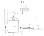
以下に、添付の図面に基づいて本発明の好ましい実施例を説明する。図1は本発明を適用した携帯刈払機の概略図である。図1において、刈払機1は内燃エンジン2を備えており、この内燃エンジン2は、例えば空冷2ストローク単気筒エンジンであるが、4サイクルエンジンであってもよい。刈払機1は、内燃エンジン2を点火するエネルギ源を構成する発電器4を補器として備えている。発電器4は、既知のように、クランクシャフト(図示せず)に同軸に設けられたロータの外周部分に設置された磁石と、このロータに隣接して配設された点火用コイルとで構成され、この点火用コイルで生成される起電力が点火エネルギ源として利用される。発電器4は、点火コイルとは別に電子機器用のコイルを備え、この電子機器用のコイルで生成される起電力がマイコンで構成されるコントローラ10や後に説明する衝撃センサ16に供給される。
Hereinafter, preferred embodiments of the present invention will be described with reference to the accompanying drawings. FIG. 1 is a schematic view of a portable brush cutter to which the present invention is applied. In FIG. 1, the brush cutter 1 includes an
刈払機1は、従来と同様に、内燃エンジン2の出力が遠心クラッチ12を介して刃物14に伝達される。言うまでもないことであるが、内燃エンジン2が所定の回転数に達すると遠心クラッチ12がクラッチON状態となってエンジン2の動力が刃物14に伝達され、エンジン回転数が所定の回転数よりも低下すると遠心クラッチ12がクラッチOFF状態となってエンジン2から刃物14への動力伝達が遮断される。
In the brush cutter 1, the output of the
刈払機1は、この刈払機1に加わる衝撃を検知する衝撃センサ16を備えている。この衝撃センサ16が衝撃を検知すると、点火プラグ8に対する高電圧の供給が停止され、これによりエンジン2の運転が強制終了される。すなわち、作業中に刃物14が石に当たってキックバック現象が現れた場合や、刈払機1が落下した場合など作業者の安全にとって好ましくない現象が発生したときにエンジン2を強制停止させることで作業者の安全を確保することができる。この種の安全装置に関する従来技術として特開2006−288296号公報を挙げることができる。したがって、この特開2006−288296号公報の全文を、この明細書に援用する。
The brush cutter 1 includes an
上記安全装置に含まれるセンサ類は上記の衝撃センサ16に限定されず、特開平4−158714号公報に見られるように刈払機のハンドルに設けた停止レバー又は圧力センサであってもよいし、マニュアルスイッチであってもよい(実開昭52−153995号公報)。他にも、圧電素子からなる衝撃センサ(特開平8−187024号公報)、エンジンのクランクシャフトと遠心クラッチの出力軸との間の相対変位を検出するセンサ(特開平8−187024号公報)、操作チューブの傾斜角度を検出する水銀スイッチ(特開昭62−198320号公報)などであってもよい。したがって、上記の特開平4−158714号公報、実開昭52−153995号公報、特開平8−187024号公報、特開昭62−198320号公報の各々の全文を、この明細書に援用することでその説明を省略する。
Sensors included in the safety device are not limited to the
図1の刈払機1は、上記のエンジン強制停止制御に加えて、このエンジン強制停止制御を実行することに伴って遠心クラッチ12がクラッチOFFした直後に刃物14の制動を開始するブレーキ機構18を備えている。すなわち、遠心クラッチ12がクラッチOFFすることで、刃物14は慣性運動により回転し続けるが、ブレーキ機構18は、この慣性運動している刃物14を制動して刃物14の回転を完全に停止させる。このことから、ブレーキ機構18は、遠心クラッチ12の被動部材(出力部材)から刃物14に至る動力伝達経路を構成する部材に臨んで配設される。
In addition to the engine forced stop control described above, the brush cutter 1 in FIG. 1 includes a
ブレーキ機構18は、ブレーキシューを備えた電磁ブレーキであってもよいが、好ましくは電磁石ブレーキであるのがよい。このブレーキ機構18を構成する電磁石ブレーキは、従来と同様にコイルとコアとで構成され、コイルに電流を流すことによって、コアが、上記動力伝達経路を構成する部材(具体的には例えば遠心クラッチ12の被動側部材であるクラッチドラム)に向けて移動し、最終的には、コアが、遠心クラッチの出力部材を含む動力伝達経路を構成する部材に電磁吸着することで刃物14を完全停止させる。
The
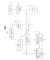
図2は、エンジンの緊急停止及びこれに伴ってエンジン回転数が低下し遠心クラッチ12がクラッチOFF状態になった後、このクラッチOFFの直後にブレーキ機構18の動作を開始させる制御の全体系統図である。
FIG. 2 is an overall system diagram of control in which the operation of the
図2を参照して、補器の発電器4が生成した電力は第1の定電源回路20によって12Vの電圧に調整され、12Vの電圧が衝撃センサ16に供給される。また、第2の定電源回路22によって5Vに調整され、この5Vの電圧がコントローラ(マイコン)10に供給されてマイコン10が駆動される。後に図4を参照して説明するが、電磁石ブレーキ機構18は、発電器4をエネルギ源とする第1コンデンサ24を有し、この第1コンデンサ24に蓄えられた電荷を使って電磁石が駆動されることにより遠心クラッチ12が制動される。発電器4が生成した電力はエンジン回転数検知回路26に入力され、このエンジン回転数検知回路26の信号がコントローラ(マイコン)10に供給される。
Referring to FIG. 2, the electric power generated by
エンジン回転数検知回路26は、遠心クラッチ12のクラッチOFFタイミングを検出するクラッチOFFタイミング検出手段を実質的に構成するものである。エンジン回転数検知回路26は第1リセットIC28(図4)を含んでおり、この第1リセットIC28は、エンジン回転数の変化に伴う発電器4の発電電圧の変化に応動し、所定の電圧を境に出力を反転する出力反転素子として使われており、遠心クラッチ12がクラッチOFFするエンジン回転数を発電器4の発電電圧によって検出するエンジン回転数検知手段を実質的に構成している。
The engine
このように第1リセットIC28によって、遠心クラッチ12がクラッチOFFするエンジン回転数を検知することにより、従来のエンジン回転数検知手段に比べて小型、安価、軽量、低消費電力という利点がある。
Thus, by detecting the engine speed at which the centrifugal clutch 12 is turned off by the
コントローラ10から制御信号(ブレーキON信号)が電磁石ブレーキ機構18に供給されると、この電磁石ブレーキ機構18の第1コンデンサ24の電荷を使って電磁石が駆動され、電磁石のコアが遠心クラッチ12のクラッチドラムに接近し、次いでこのクラッチドラムに電磁吸着することでクラッチドラムの回転つまり刃物14の回転が完全停止される。
When a control signal (brake ON signal) is supplied from the
電磁石ブレーキ機構18とコントローラ10との間にはブレーキ保持回路30が介装されている。このブレーキ保持回路30は第2のコンデンサ32を含んでおり、この第2のコンデンサ32を電源として、ブレーキ保持回路30は電磁石ブレーキ機構18に対するブレーキON信号を保持する。これにより電磁石ブレーキ機構18の第1コンデンサ24を電源とするクラッチドラムの制動が継続される。
A
好ましくは、第2の定電源回路22とコントローラ10との間に電源切断回路40を介装するのがよい。電源切断回路40はリセットIC42(図4)を含んでいる。
Preferably, a power cut-
刈払機1に加わる衝撃、例えばキックバックによる衝撃を衝撃センサ16が検知すると、衝撃センサ16から検知信号を受け取ったコントローラ10は、点火回路6を強制的に接地させることにより、点火プラグ8への電源供給を停止させる。これによりエンジン2の回転数は低下し、これに伴って発電器4の発電能力が低下する。発電器4が生成する電力の電圧は一般的にエンジン回転数によって規定することができる。
When the
エンジン回転数検知回路26に含まれる第1のリセットIC28は、エンジン回転数が低下する過程で遠心クラッチ12がクラッチOFFする回転数(例えば3800rpm)の時の発電器4が発電電圧を境に出力を反転するリセットICが選択される。したがって、エンジン強制停止制御を実行した結果、エンジン2の回転数が低下することになるが、遠心クラッチ12がクラッチOFF状態になる回転数までエンジン回転数が低下すると、このエンジン回転数を検知回路26で検知して、エンジン回転数検知回路26からコントローラ10にタイミング検知信号(Lowレベルの信号)が供給される。
The
他方、電源切断回路40に含まれる第2のリセットIC42は、エンジン2の運転が停止する直前の回転数(例えば約800rpm)の時の発電器4の発電電圧を境に出力を反転するリセットICが選択される。したがって、エンジン2の回転数が約800rpmまで低下すると、第2のリセットIC42の出力が反転し、電源切断回路40は、発電器4の発電電力を電源としたコントローラ10への電源供給を遮断する。これにより、極めて低い電圧の電源がコントローラ10に供給されることに伴うコントローラ10の誤動作を防止することができる。
On the other hand, the
図3は、コントローラ10の制御例を示すフローチャートである。先ず、ステップS10で衝撃センサ16の衝撃検知を受けてエンジン2が緊急停止されたか否かが判断され、このステップS10においてYESと判定されたときには、エンジン強制停止制御が実行されたとしてステップS11に進む。
FIG. 3 is a flowchart illustrating a control example of the
ステップS11では、エンジン回転数検知回路26(第1のリセットIC28)からの入力信号がLowレベルに変化したか否かの判断が行われる。上記ステップS10において、エンジン2の点火を停止することでエンジン2の運転を緊急停止させる制御が実行されるとエンジン2の回転数が急激に低下する。そして、エンジン2の回転数が低下し、これに伴って発電器4の発電電圧が所定の電圧まで低下するとエンジン回転数検知回路26の第1リセットIC28が動作してエンジン回転数検知回路26からLowレベル信号が出力される。上述したように、このLowレベル信号が出力されるタイミングは、遠心クラッチ12がクラッチOFF状態になった直後である。そして、このLowレベル信号がコントローラ10に入力されると、ステップS12に進んで、ブレーキ保持回路30にブレーキON信号(Hiレベルの信号)が出力される。ブレーキ保持回路30は、このブレーキON信号を受けて電磁石ブレーキ機構18に対してブレーキ駆動信号を出力すると共にブレーキ保持回路30に含まれる第2コンデンサ32の蓄電を開始する。
In step S11, it is determined whether or not the input signal from the engine speed detection circuit 26 (first reset IC 28) has changed to a low level. In step S <b> 10, when the control for urgently stopping the operation of the
この状態は、僅かな時間であるが、電源切断回路40によってコントローラ(マイコン)10がシャットダウンされるまで継続される(S13)。コントローラ10がシャットダウンした後は、ブレーキ保持回路30の第2コンデンサ32の電荷を使って電磁石ブレーキ機構18に対するブレーキ駆動信号が保持される。
This state continues for a short time until the controller (microcomputer) 10 is shut down by the power-off circuit 40 (S13). After the
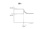
電磁石ブレーキ機構18は、ブレーキ保持回路30から供給されるブレーキ駆動信号(ブレーキON信号)を受けて、電磁石ブレーキ機構18の第1コンデンサ24の電荷を電源として電磁石18が駆動され、この電磁石18によって、遠心クラッチ12の慣性運動しているクラッチドラムが制動される。図6は、ブレーキON信号に伴う第1コンデンサ24の電流、電圧波形を示す。
The
エンジン2の緊急運転停止に伴う発電器4の急激な発電能力低下つまり発電電圧の急激な低下を使うことで、この発電器4の発電電圧によって的確に遠心クラッチ12がクラッチOFFするエンジン回転数を検知することができる。そして、その直後に電磁石ブレーキ機構18が動作することから、慣性運動している刃物14の回転を早期に停止させることができ、また刃物14の回転を停止させるのに必要とされる制動エネルギも僅かで足りる。また、電磁石ブレーキ機構18はコアの電磁吸着を使って遠心クラッチ12のクラッチドラムを制動することから、第1コンデンサ24の有限の電荷によってクラッチドラムを完全停止させることができる(刃物14の完全停止)。
By using the sudden decrease in power generation capacity of the
また、第2リセットIC42を含む電源切断回路40を組み込むことにより、発電器4の発電能力が極端に低下するエンジン回転数を第2リセットIC42で検知して、コントローラ10への電源供給を停止することでコントローラ10の誤作動を確実に回避することができる。このことは刃物を備えた作業機100の安全対策にとって極めて重要なことである。
Further, by incorporating the power cut-
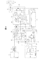
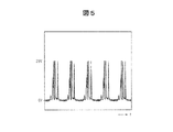
図4は、上記ブレーキ機構18の制御を実現する回路の一例である。図4の制御回路を参照して、発電器4の電源回路から最大20Vのパルス状の電位が出力される。図5は、エンジン回転数3,000rpmのときの発電器4の電源回路の出力波形を示す。発電器4の発電電位はエンジン回転数に対応し、エンジン回転数が高くなるほど発電電位は高くなる。なお、エンジン2のアイドル回転数は3000rpmプラスマイナス500rpmである。遠心クラッチ12は、そのクラッチON/OFFが約3800rpmのエンジン回転数のときに実行されるように設定されている。
FIG. 4 is an example of a circuit that realizes control of the
発電器4の電源回路から出力されたパルス状の電位は、第1の定電源回路20によって12V(ボルト)の定電圧に調整され、この12Vの電圧が衝撃センサ16に供給されると共に、第2の定電源回路22によって5Vの定電圧に調整され、この5Vの電圧によってマイコン10が駆動される。なお、電磁石ブレーキ機構18に含まれる第1コンデンサ24には発電器4から電源が供給される。
The pulsed potential output from the power supply circuit of the
衝撃センサ16を構成する例えば加速度センサが所定値以上の加速度を検知すると、この衝撃センサ16から衝撃検知信号がマイコン10に入力され、この衝撃検知信号を受け取ったマイコン10はエンジン停止回路48にエンジン停止信号を出力する。エンジン停止回路48は、マイコン10からエンジン停止信号を受け取ると点火回路6を接地することで、点火プラグ8に対する高電圧供給を停止する。これによりエンジン2は運転停止状態になり、このエンジンの強制停止に伴ってエンジン回転数は急激に低下することになる。そして、これに伴って発電器4の発電電位が急速に低下する。
When, for example, an acceleration sensor that constitutes the
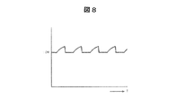
エンジン回転数検知回路26に含まれる第1リセットIC28には、発電器4の発電電位が抵抗R1、R2により分圧されて入力される。図7は、第1リセットIC28に入力される電位の波形を示す。この図7から平滑化された電位が第1リセットIC28に入力されるのが判るであろう。この平滑化は、前述した第1平滑化回路44のコンデンサC3による。そして、この第1リセットIC28の入力電位が4Vを下回ると、第1リセットIC28の出力はHiレベル信号からLowレベル信号に変化して、このLowレベル信号がコンデンサC6を介してマイコン10に入力される。図8は第1リセットIC28のLowレベル信号の波形を示す図である。第1リセットIC28とマイコン10との間に、一方の端子を接地したコンデンサC6を接続することによって第1リセットIC28の出力波形の立ち上がりが鈍くなっていることが判るであろう。仮にコンデンサC6が無いとすると、第1リセットIC28の出力波形にノイズが加わって、この結果マイコン10が誤作動する可能性がある。ここに、コンデンサC6の代わりに、第1リセットIC28に直列にコイルを接続してもよい。
The
なお、抵抗R1、R2による分圧電位の4Vは、約3500rpmのエンジン回転数に相当する。したがって、遠心クラッチ12がクラッチON状態からOFF状態に変化した直後のエンジン回転数に相当する。 In addition, 4V of the divided potential by the resistors R1 and R2 corresponds to an engine speed of about 3500 rpm. Accordingly, this corresponds to the engine speed immediately after the centrifugal clutch 12 changes from the clutch ON state to the OFF state.
マイコン10は、上述した第1リセットIC28からLow信号を受け取ると、マイコン10からブレーキ保持回路30に対してHiレベル信号が出力され、これによりブレーキ保持回路30に含まれる第2コンデンサ32の蓄電が実行されると共にブレーキ保持回路30のトランジスタTr1、Tr2によってブレーキ機構18の電磁石コイルの接地側端子が接地される。この状態は、後述するマイコン10がシャットダウンした後は、ブレーキ保持回路30のコンデンサ32が蓄えている電荷によって保持される。
When the
ブレーキ機構18の電磁石コイルの接地側端子が接地されると、ブレーキ機構18に含まれる第1コンデンサ24が蓄えている電荷によって電磁石コイルに電流が流れ、これにより電磁石のコアが前述した遠心クラッチ12の被動側部材であるクラッチドラムに向けて移動し、そして、このクラッチドラムに電磁吸着する。これにより、遠心クラッチ12のクラッチOFFにより慣性運動している刃物14の回転が完全停止する。この電磁吸着は、第1コンデンサ24の電荷が無くなるまで継続される。好ましくは、電磁石はコアを原位置(待機位置)に復帰させるための付勢手段を備えているのが良く、コンデンサ24の電荷が無くなって電磁石のコアが消磁するのに伴ってコアが自動的に原位置に復帰するようにするのがよい。これにより、作業者がブレーキ機構18の制動を解除する操作無しに、エンジン2を再起動することで作業を開始することができる。
When the ground-side terminal of the electromagnet coil of the
エンジン強制停止の話に戻って、エンジン回転数が更に低下して発電器4の発電電位が更に低下して、第2定電源回路22(REG2)の出力電位が4V(ボルト)を下回ると、電源切断回路40に含まれる第2のリセットIC42が接地され、これによりトランジスタTr4を介したマイコン10への電源供給が停止され、マイコン10はシャットダウンする。このマイコン10の強制的なシャットダウンにより、前述したように、発電器4の発電能力低下に伴うコントローラ10の誤作動を確実に回避することができる。
Returning to the topic of forced engine stop, when the engine speed further decreases, the power generation potential of the
以上、本発明の一実施例を説明したが、本発明はこれに限定されることなく、例えば以下の変形例や適用例を包含するものである。 As mentioned above, although one Example of this invention was described, this invention is not limited to this, For example, the following modifications and application examples are included.
(1)エンジン始動時に刃物が回転しないようにブレーキをかけた状態でエンジン始動を行うことが奨励されているが、エンジン始動後、作業者がスロットルレバーを操作してエンジン回転数を上昇させたときにブレーキを自動解除するブレーキ自動解除システムを組み込んだ可搬作業機において、エンジン回転数が所定の回転数を越えたのを検知するのに、当該所定の回転数のときの発電器4の発電電位を介してリセットICで所定の回転数を検知してもよい。
(1) Although it is encouraged to start the engine with the brake applied so that the blade does not rotate when the engine is started, the operator increased the engine speed by operating the throttle lever after starting the engine. In a portable work machine that incorporates an automatic brake release system that automatically releases the brake, sometimes the
(2)エンジン2のアイドル運転が所定時間(例えば5秒間)継続したときに、これをタイマとリセットICとの組み合わせでエンジンの運転を強制停止させるようにしてもよい。
(2) When the idle operation of the
(3)例えば先述した特許文献4に開示の潤滑システムを備えたエンジンにおいて、潤滑システムに含まれるオイルポンプを所定のエンジン回転数でON/OFFする制御を行うときに、当該所定のエンジン回転数の検知にリセットICを用いてもよい。
(3) For example, in an engine equipped with the lubrication system disclosed in
(4)電磁クラッチを含む作業機において、この電磁クラッチのON/OFFを所定のエンジン回転数で切り替えるために、リセットICを用いて、この所定のエンジン回転数のときの発電器4の発電電位を介して所定のエンジン回転数を検知してもよい。
(4) In a working machine including an electromagnetic clutch, in order to switch ON / OFF of the electromagnetic clutch at a predetermined engine speed, a reset IC is used to generate a power generation potential of the
(5)前述した特許文献5のように、複数のしきい値(複数の所定のエンジン回転数)を用意し、エンジン回転数が所定の範囲(特許文献5では3,900rpm乃至4,400rpm)にある時間が所定時間経過したときにエンジン回転数を低下させる制御を行う場合に、この複数のしきい値に代えて複数のリセットICを使って発電器4の発電電位を介してエンジン回転数を検知するようにしてもよい。
(5) As described in Patent Document 5, a plurality of threshold values (a plurality of predetermined engine speeds) are prepared, and the engine speed is in a predetermined range (3,900 rpm to 4,400 rpm in Patent Document 5). When performing control to reduce the engine speed when the predetermined time has elapsed, the engine speed is detected via the power generation potential of the
(6)前述した特許文献5に開示のエンジンの過回転防止に関連して、チェーンソーでは、木を切断する負荷を念頭に入れて許容できる最大回転数を設定していることから、無負荷でスロットルレバーを全開したときにはエンジン回転数が過回転になってエンジンが焼き付いてしまう可能性がある。これを防止するために本願発明を適用して、エンジン回転数が所定の回転数に達したときに、そのときの発電器の発電電圧をリセットICで検知してエンジン回転数を抑制する制御を実行させてもよい。 (6) In connection with the engine over-rotation prevention disclosed in Patent Document 5 described above, the chainsaw sets the maximum number of rotations that can be allowed in consideration of the load for cutting the tree. When the throttle lever is fully opened, the engine speed may become excessive and the engine may burn out. In order to prevent this, the present invention is applied, and when the engine speed reaches a predetermined speed, the power generation voltage of the power generator at that time is detected by a reset IC to control the engine speed. It may be executed.
(7)ブロワーは、吸い込んだ石によってブロワーの羽根を破損することがある。羽根が破損すると、ブロワーは仕事をしないためエンジン回転数が高くなって過回転状態になる。これを防止するために本願発明を適用して、エンジン回転数が所定の回転数に達したときに、そのときの発電器の発電電圧をリセットICで検知してエンジン回転数を抑制する制御を実行させてもよい。
(8)動力噴霧器は、タンク内の薬液が所定のレベルよりも少なくなると薬液の噴霧ができなくなり、エンジンが過回転状態になり易い。これを防止するために本願発明を適用して、エンジン回転数が所定の回転数に達したときに、そのときの発電器の発電電圧をリセットICで検知してエンジン回転数を抑制する制御を実行させてもよい。
(7) The blower may damage the blade of the blower due to the sucked stone. When the blades are damaged, the blower does not work, so the engine speed increases and an overspeed state occurs. In order to prevent this, the present invention is applied, and when the engine speed reaches a predetermined speed, the power generation voltage of the power generator at that time is detected by a reset IC to control the engine speed. It may be executed.
(8) When the chemical solution in the tank is less than a predetermined level, the power sprayer cannot spray the chemical solution, and the engine is likely to be over-rotated. In order to prevent this, the present invention is applied, and when the engine speed reaches a predetermined speed, the power generation voltage of the power generator at that time is detected by a reset IC to control the engine speed. It may be executed.
(9)動力噴霧器で水を散布するときに、給水ホースが破損したりすると水を吸い上げることができなくなり、エンジンが過回転状態になり易い。これを防止するために本願発明を適用して、エンジン回転数が所定の回転数に達したときに、そのときの発電器の発電電圧をリセットICで検知してエンジン回転数を抑制する制御を実行させてもよい。
(10)枝葉を破砕するウッドチッパーにおいて、例えば許容できない大きな枝によってエンジンが過負荷状態になり、エンジン回転数が急激に低下することがある。このエンジン回転数が、作業中の正常な回転数から急激にエンジン回転数が低下したときに、発電器の発電電圧が急激に低下して所定の電圧以下になったことをリセットICで検知して、この異常状態を作業者に知らせるために例えば警報ランプの点滅などの警報を発するようにしてもよい。
(9) When water is sprayed with a power sprayer, if the water supply hose is damaged, water cannot be sucked up, and the engine is likely to be in an overspeed state. In order to prevent this, the present invention is applied, and when the engine speed reaches a predetermined speed, the power generation voltage of the power generator at that time is detected by a reset IC to control the engine speed. It may be executed.
(10) In a wood chipper that crushes branches and leaves, for example, an unacceptably large branch may overload the engine, and the engine speed may rapidly decrease. When the engine speed has suddenly decreased from the normal speed during work, the reset IC detects that the power generation voltage of the generator has suddenly decreased to below the specified voltage. In order to notify the operator of this abnormal state, an alarm such as a flashing alarm lamp may be issued.
(11)オートバイのレースでは、変速段を操作して最適なエンジン出力を使った走行が行われる。したがって、各変速段でのトルク曲線のピークを越えた所定のエンジン回転数になったときに、その時の発電器の発電電圧をリセットICで検知してドライバに変速を促す警報(シフトアップインジケータ)を発するようにしてもよい。
(12)キャブレター(気化器)を備えたエンジンでは、エアスクリュー、パイロットスクリュー、スロージェットの調整が行われる。例えば低速での調整において、例えば3,500rpmの回転数で燃料を多めに噴射するように調整するとエンジン回転数が低下し始める。この燃料の調整において、3,000rpm近辺までエンジン回転数が低下したときに調整を終えることで気化器のセッティング作業が終わる。このセッティングに本願発明を適用して、3,000rpm近辺までエンジン回転数が低下したときの発電器の発電電圧をリセットICで検知して、例えばセッティング作業終了ランプを点灯させるようにしてもよい。高速のセッティングも同様である。
(11) In a motorcycle race, traveling using the optimum engine output is performed by operating the gear position. Therefore, an alarm (shift-up indicator) that prompts the driver to shift gears by detecting the power generation voltage of the generator at that time with the reset IC when the engine speed reaches the peak of the torque curve at each gear. May be issued.
(12) In an engine equipped with a carburetor (vaporizer), adjustment of an air screw, a pilot screw, and a slow jet is performed. For example, in an adjustment at a low speed, for example, if an adjustment is made so that a large amount of fuel is injected at a rotation speed of 3,500 rpm, the engine speed starts to decrease. In this fuel adjustment, the carburetor setting work is completed by finishing the adjustment when the engine speed decreases to around 3,000 rpm. The present invention may be applied to this setting, and the power generation voltage of the power generator when the engine speed is reduced to around 3,000 rpm is detected by a reset IC, for example, a setting work end lamp may be turned on. The same is true for high-speed settings.
本発明は、刈払機、チェーンソー、ヘッジトリマ、研磨切断機、送風機(ブロワー)、農薬や肥料を散布する動力付き噴霧機、高圧洗浄機、動力付きドリル、芝刈り機、田植機、除雪機、剪定後の枝葉を細かく破砕するウッドチッパーなどの作業機やオートバイ(motorcycle)に搭載される比較的小型のガソリンエンジン又はディーゼルエンジンに適用することができる。 The present invention includes brush cutters, chainsaws, hedge trimmers, polishing cutters, blowers, powered sprayers that spray agricultural chemicals and fertilizers, high pressure washers, powered drills, lawn mowers, rice transplanters, snowplows, pruners The present invention can be applied to a relatively small gasoline engine or diesel engine mounted on a working machine such as a wood chipper or a motorcycle that crushes the branches and leaves later.
1 刈払機
2 内燃エンジン(単気筒2ストロークエンジン)
4 発電器
8 点火プラグ
10 コントローラ(マイコン)
12 遠心クラッチ
14 刃物
16 衝撃センサ(加速度センサ)
18 ブレーキ機構(電磁石ブレーキ)
26 エンジン回転数検知回路
28 エンジン回転数検知回路の第1リセットIC
40 コントローラの電源供給を遮断する電源切断回路40
42 電源切断回路の第2リセットIC
1
4
12 Centrifugal clutch 14
18 Brake mechanism (electromagnetic brake)
26 Engine
40 Power-
42 Second reset IC for power-off circuit
Claims (5)
前記エンジンによって駆動される発電器と、
該発電器に接続された第1のリセットICとを有し、
該第1のリセットICの出力反転により、所定のエンジン回転数を検知することを特徴とするエンジン回転数検知装置。 An engine speed detector for detecting a predetermined engine speed,
A generator driven by the engine;
A first reset IC connected to the generator;
An engine speed detecting device for detecting a predetermined engine speed by reversing the output of the first reset IC.
該第1の定電源回路と前記発電器との間に前記第1のリセットICが接続されている、請求項2に記載のエンジン回転数検知回路。 A first constant power circuit including a capacitor is connected to the generator;
The engine speed detection circuit according to claim 2, wherein the first reset IC is connected between the first constant power supply circuit and the generator.
前記発電器によって駆動されるマイコンと、
該マイコンと前記発電器との間に介装された第2の定電源回路と、
該第2の定電源回路と前記マイコンとの間に介装された電源切断回路とを有し、
該電源切断回路が第2のリセットICを有し、該第2のリセットICの出力反転によって前記マイコンへの電源供給が遮断されることを特徴とする作業機。 A working machine equipped with the engine according to any one of claims 1 to 4,
A microcomputer driven by the generator;
A second constant power supply circuit interposed between the microcomputer and the generator;
A power-off circuit interposed between the second constant power circuit and the microcomputer;
The working machine characterized in that the power cut-off circuit has a second reset IC, and the power supply to the microcomputer is cut off by the inversion of the output of the second reset IC.
Priority Applications (1)
| Application Number | Priority Date | Filing Date | Title |
|---|---|---|---|
| JP2011011446A JP2012154183A (en) | 2011-01-21 | 2011-01-21 | Engine speed detection device having auxiliary power generator |
Applications Claiming Priority (1)
| Application Number | Priority Date | Filing Date | Title |
|---|---|---|---|
| JP2011011446A JP2012154183A (en) | 2011-01-21 | 2011-01-21 | Engine speed detection device having auxiliary power generator |
Publications (2)
| Publication Number | Publication Date |
|---|---|
| JP2012154183A true JP2012154183A (en) | 2012-08-16 |
| JP2012154183A5 JP2012154183A5 (en) | 2013-12-26 |
Family
ID=46836191
Family Applications (1)
| Application Number | Title | Priority Date | Filing Date |
|---|---|---|---|
| JP2011011446A Pending JP2012154183A (en) | 2011-01-21 | 2011-01-21 | Engine speed detection device having auxiliary power generator |
Country Status (1)
| Country | Link |
|---|---|
| JP (1) | JP2012154183A (en) |
Cited By (1)
| Publication number | Priority date | Publication date | Assignee | Title |
|---|---|---|---|---|
| JP2012152109A (en) * | 2011-01-21 | 2012-08-16 | Yamabiko Corp | Braking device of portable implement with centrifugal clutch |
Citations (13)
| Publication number | Priority date | Publication date | Assignee | Title |
|---|---|---|---|---|
| JPS57200644U (en) * | 1981-06-18 | 1982-12-20 | ||
| JPS632163U (en) * | 1986-06-24 | 1988-01-08 | ||
| JPH01113563A (en) * | 1988-01-12 | 1989-05-02 | Kubota Ltd | Engine control device |
| JPH08177593A (en) * | 1994-12-21 | 1996-07-09 | Hitachi Ltd | Diesel engine rotation stop device |
| JPH09112332A (en) * | 1995-10-24 | 1997-04-28 | Kokusan Denki Co Ltd | Deciding method for rotation speed of internal combustion engine |
| JPH10299548A (en) * | 1997-04-23 | 1998-11-10 | Kokusan Denki Co Ltd | Electronic governor device for internal combustion engine |
| JP2002345298A (en) * | 2001-05-17 | 2002-11-29 | Mitsubishi Electric Corp | Control device for vehicle generator |
| JP2003047296A (en) * | 2001-08-02 | 2003-02-14 | Honda Motor Co Ltd | Engine generator inverter device |
| JP2003174797A (en) * | 2001-12-06 | 2003-06-20 | Denso Corp | Control device for vehicle generator |
| JP2003314346A (en) * | 2002-04-19 | 2003-11-06 | Honda Motor Co Ltd | General-purpose engine speed control device |
| JP2005147016A (en) * | 2003-11-17 | 2005-06-09 | Kokusan Denki Co Ltd | Control device for internal combustion engine |
| JP2005155544A (en) * | 2003-11-27 | 2005-06-16 | Kokusan Denki Co Ltd | Engine speed control device for internal combustion engine |
| JP2008274949A (en) * | 2007-04-30 | 2008-11-13 | Andreas Stihl Ag & Co Kg | Method of operating an internal combustion engine |
-
2011
- 2011-01-21 JP JP2011011446A patent/JP2012154183A/en active Pending
Patent Citations (13)
| Publication number | Priority date | Publication date | Assignee | Title |
|---|---|---|---|---|
| JPS57200644U (en) * | 1981-06-18 | 1982-12-20 | ||
| JPS632163U (en) * | 1986-06-24 | 1988-01-08 | ||
| JPH01113563A (en) * | 1988-01-12 | 1989-05-02 | Kubota Ltd | Engine control device |
| JPH08177593A (en) * | 1994-12-21 | 1996-07-09 | Hitachi Ltd | Diesel engine rotation stop device |
| JPH09112332A (en) * | 1995-10-24 | 1997-04-28 | Kokusan Denki Co Ltd | Deciding method for rotation speed of internal combustion engine |
| JPH10299548A (en) * | 1997-04-23 | 1998-11-10 | Kokusan Denki Co Ltd | Electronic governor device for internal combustion engine |
| JP2002345298A (en) * | 2001-05-17 | 2002-11-29 | Mitsubishi Electric Corp | Control device for vehicle generator |
| JP2003047296A (en) * | 2001-08-02 | 2003-02-14 | Honda Motor Co Ltd | Engine generator inverter device |
| JP2003174797A (en) * | 2001-12-06 | 2003-06-20 | Denso Corp | Control device for vehicle generator |
| JP2003314346A (en) * | 2002-04-19 | 2003-11-06 | Honda Motor Co Ltd | General-purpose engine speed control device |
| JP2005147016A (en) * | 2003-11-17 | 2005-06-09 | Kokusan Denki Co Ltd | Control device for internal combustion engine |
| JP2005155544A (en) * | 2003-11-27 | 2005-06-16 | Kokusan Denki Co Ltd | Engine speed control device for internal combustion engine |
| JP2008274949A (en) * | 2007-04-30 | 2008-11-13 | Andreas Stihl Ag & Co Kg | Method of operating an internal combustion engine |
Cited By (1)
| Publication number | Priority date | Publication date | Assignee | Title |
|---|---|---|---|---|
| JP2012152109A (en) * | 2011-01-21 | 2012-08-16 | Yamabiko Corp | Braking device of portable implement with centrifugal clutch |
Similar Documents
| Publication | Publication Date | Title |
|---|---|---|
| US9103289B2 (en) | Method for controlling the limiting of the rotational speed of a combustion engine | |
| RU2665557C2 (en) | Method of hand-held working tool operation | |
| JP4644573B2 (en) | Rotation speed protection circuit for centrifugal clutch | |
| CN103443418B (en) | The driving portable working machine of hybrid power | |
| US11639681B2 (en) | Internal combustion engine with electric starting system | |
| US8161931B2 (en) | Method for operating an internal combustion engine | |
| JP2014117761A (en) | Power tool | |
| CN103161591A (en) | Device and method for operating a hand-held working apparatus | |
| US11085412B2 (en) | Internal combustion engine with electric starting system | |
| CN108367369B (en) | Handheld power tool, associated control system, use thereof, and method of controlling the same | |
| EP3237739B1 (en) | Internal combustion engine and method for safe starting the same | |
| US20110061355A1 (en) | Grass mowing machine with engine speed and voltage limiter | |
| JP3813921B2 (en) | Internal combustion engine start method and starter | |
| JP5739676B2 (en) | Brake device for portable work machine with centrifugal clutch | |
| JP4980270B2 (en) | Engine start control device | |
| CN108368818B (en) | Handheld power tool and control system, use and control method therefor | |
| JP2014008027A (en) | Hybrid system and portable equipment provided with the same | |
| JP7820256B2 (en) | General-purpose engine speed control device | |
| JP2015124772A (en) | Engine working machine | |
| JP2016220604A (en) | Portable engine-driven work machine | |
| JP2014148932A (en) | Engine work machine | |
| JP2013170522A (en) | Control device of engine | |
| JPH02109746A (en) | Protecting device for centrifugal automatic clutch | |
| TH35434B (en) | Engine control unit | |
| TH60500A (en) | Engine control unit |
Legal Events
| Date | Code | Title | Description |
|---|---|---|---|
| A521 | Written amendment |
Free format text: JAPANESE INTERMEDIATE CODE: A523 Effective date: 20131112 |
|
| A621 | Written request for application examination |
Free format text: JAPANESE INTERMEDIATE CODE: A621 Effective date: 20131112 |
|
| A977 | Report on retrieval |
Free format text: JAPANESE INTERMEDIATE CODE: A971007 Effective date: 20140417 |
|
| A131 | Notification of reasons for refusal |
Free format text: JAPANESE INTERMEDIATE CODE: A131 Effective date: 20140423 |
|
| A02 | Decision of refusal |
Free format text: JAPANESE INTERMEDIATE CODE: A02 Effective date: 20140819 |