JP2012154209A - 内燃機関の制御装置及び内燃機関 - Google Patents
内燃機関の制御装置及び内燃機関 Download PDFInfo
- Publication number
- JP2012154209A JP2012154209A JP2011012294A JP2011012294A JP2012154209A JP 2012154209 A JP2012154209 A JP 2012154209A JP 2011012294 A JP2011012294 A JP 2011012294A JP 2011012294 A JP2011012294 A JP 2011012294A JP 2012154209 A JP2012154209 A JP 2012154209A
- Authority
- JP
- Japan
- Prior art keywords
- fuel
- intake
- valve
- internal combustion
- combustion engine
- Prior art date
- Legal status (The legal status is an assumption and is not a legal conclusion. Google has not performed a legal analysis and makes no representation as to the accuracy of the status listed.)
- Pending
Links
Images











Classifications
-
- F—MECHANICAL ENGINEERING; LIGHTING; HEATING; WEAPONS; BLASTING
- F02—COMBUSTION ENGINES; HOT-GAS OR COMBUSTION-PRODUCT ENGINE PLANTS
- F02D—CONTROLLING COMBUSTION ENGINES
- F02D41/00—Electrical control of supply of combustible mixture or its constituents
- F02D41/30—Controlling fuel injection
- F02D41/3011—Controlling fuel injection according to or using specific or several modes of combustion
- F02D41/3017—Controlling fuel injection according to or using specific or several modes of combustion characterised by the mode(s) being used
- F02D41/3023—Controlling fuel injection according to or using specific or several modes of combustion characterised by the mode(s) being used a mode being the stratified charge spark-ignited mode
- F02D41/3029—Controlling fuel injection according to or using specific or several modes of combustion characterised by the mode(s) being used a mode being the stratified charge spark-ignited mode further comprising a homogeneous charge spark-ignited mode
-
- F—MECHANICAL ENGINEERING; LIGHTING; HEATING; WEAPONS; BLASTING
- F02—COMBUSTION ENGINES; HOT-GAS OR COMBUSTION-PRODUCT ENGINE PLANTS
- F02D—CONTROLLING COMBUSTION ENGINES
- F02D13/00—Controlling the engine output power by varying inlet or exhaust valve operating characteristics, e.g. timing
- F02D13/02—Controlling the engine output power by varying inlet or exhaust valve operating characteristics, e.g. timing during engine operation
- F02D13/0261—Controlling the valve overlap
-
- F—MECHANICAL ENGINEERING; LIGHTING; HEATING; WEAPONS; BLASTING
- F02—COMBUSTION ENGINES; HOT-GAS OR COMBUSTION-PRODUCT ENGINE PLANTS
- F02D—CONTROLLING COMBUSTION ENGINES
- F02D13/00—Controlling the engine output power by varying inlet or exhaust valve operating characteristics, e.g. timing
- F02D13/02—Controlling the engine output power by varying inlet or exhaust valve operating characteristics, e.g. timing during engine operation
- F02D13/0261—Controlling the valve overlap
- F02D13/0265—Negative valve overlap for temporarily storing residual gas in the cylinder
-
- F—MECHANICAL ENGINEERING; LIGHTING; HEATING; WEAPONS; BLASTING
- F02—COMBUSTION ENGINES; HOT-GAS OR COMBUSTION-PRODUCT ENGINE PLANTS
- F02D—CONTROLLING COMBUSTION ENGINES
- F02D41/00—Electrical control of supply of combustible mixture or its constituents
- F02D41/0025—Controlling engines characterised by use of non-liquid fuels, pluralities of fuels, or non-fuel substances added to the combustible mixtures
- F02D41/0047—Controlling exhaust gas recirculation [EGR]
- F02D41/005—Controlling exhaust gas recirculation [EGR] according to engine operating conditions
-
- F—MECHANICAL ENGINEERING; LIGHTING; HEATING; WEAPONS; BLASTING
- F02—COMBUSTION ENGINES; HOT-GAS OR COMBUSTION-PRODUCT ENGINE PLANTS
- F02D—CONTROLLING COMBUSTION ENGINES
- F02D41/00—Electrical control of supply of combustible mixture or its constituents
- F02D41/30—Controlling fuel injection
- F02D41/38—Controlling fuel injection of the high pressure type
- F02D41/40—Controlling fuel injection of the high pressure type with means for controlling injection timing or duration
- F02D41/401—Controlling injection timing
-
- F—MECHANICAL ENGINEERING; LIGHTING; HEATING; WEAPONS; BLASTING
- F02—COMBUSTION ENGINES; HOT-GAS OR COMBUSTION-PRODUCT ENGINE PLANTS
- F02M—SUPPLYING COMBUSTION ENGINES IN GENERAL WITH COMBUSTIBLE MIXTURES OR CONSTITUENTS THEREOF
- F02M69/00—Low-pressure fuel-injection apparatus ; Apparatus with both continuous and intermittent injection; Apparatus injecting different types of fuel
- F02M69/04—Injectors peculiar thereto
- F02M69/042—Positioning of injectors with respect to engine, e.g. in the air intake conduit
- F02M69/044—Positioning of injectors with respect to engine, e.g. in the air intake conduit for injecting into the intake conduit downstream of an air throttle valve
-
- F—MECHANICAL ENGINEERING; LIGHTING; HEATING; WEAPONS; BLASTING
- F02—COMBUSTION ENGINES; HOT-GAS OR COMBUSTION-PRODUCT ENGINE PLANTS
- F02M—SUPPLYING COMBUSTION ENGINES IN GENERAL WITH COMBUSTIBLE MIXTURES OR CONSTITUENTS THEREOF
- F02M69/00—Low-pressure fuel-injection apparatus ; Apparatus with both continuous and intermittent injection; Apparatus injecting different types of fuel
- F02M69/04—Injectors peculiar thereto
- F02M69/042—Positioning of injectors with respect to engine, e.g. in the air intake conduit
- F02M69/045—Positioning of injectors with respect to engine, e.g. in the air intake conduit for injecting into the combustion chamber
-
- F—MECHANICAL ENGINEERING; LIGHTING; HEATING; WEAPONS; BLASTING
- F02—COMBUSTION ENGINES; HOT-GAS OR COMBUSTION-PRODUCT ENGINE PLANTS
- F02D—CONTROLLING COMBUSTION ENGINES
- F02D41/00—Electrical control of supply of combustible mixture or its constituents
- F02D41/02—Circuit arrangements for generating control signals
- F02D41/04—Introducing corrections for particular operating conditions
- F02D41/06—Introducing corrections for particular operating conditions for engine starting or warming up
- F02D41/068—Introducing corrections for particular operating conditions for engine starting or warming up for warming-up
-
- Y—GENERAL TAGGING OF NEW TECHNOLOGICAL DEVELOPMENTS; GENERAL TAGGING OF CROSS-SECTIONAL TECHNOLOGIES SPANNING OVER SEVERAL SECTIONS OF THE IPC; TECHNICAL SUBJECTS COVERED BY FORMER USPC CROSS-REFERENCE ART COLLECTIONS [XRACs] AND DIGESTS
- Y02—TECHNOLOGIES OR APPLICATIONS FOR MITIGATION OR ADAPTATION AGAINST CLIMATE CHANGE
- Y02T—CLIMATE CHANGE MITIGATION TECHNOLOGIES RELATED TO TRANSPORTATION
- Y02T10/00—Road transport of goods or passengers
- Y02T10/10—Internal combustion engine [ICE] based vehicles
- Y02T10/12—Improving ICE efficiencies
-
- Y—GENERAL TAGGING OF NEW TECHNOLOGICAL DEVELOPMENTS; GENERAL TAGGING OF CROSS-SECTIONAL TECHNOLOGIES SPANNING OVER SEVERAL SECTIONS OF THE IPC; TECHNICAL SUBJECTS COVERED BY FORMER USPC CROSS-REFERENCE ART COLLECTIONS [XRACs] AND DIGESTS
- Y02—TECHNOLOGIES OR APPLICATIONS FOR MITIGATION OR ADAPTATION AGAINST CLIMATE CHANGE
- Y02T—CLIMATE CHANGE MITIGATION TECHNOLOGIES RELATED TO TRANSPORTATION
- Y02T10/00—Road transport of goods or passengers
- Y02T10/10—Internal combustion engine [ICE] based vehicles
- Y02T10/40—Engine management systems
Landscapes
- Engineering & Computer Science (AREA)
- Chemical & Material Sciences (AREA)
- Combustion & Propulsion (AREA)
- Mechanical Engineering (AREA)
- General Engineering & Computer Science (AREA)
- Electrical Control Of Air Or Fuel Supplied To Internal-Combustion Engine (AREA)
- Electrical Control Of Ignition Timing (AREA)
- Combined Controls Of Internal Combustion Engines (AREA)
Abstract
【解決手段】燃料噴射弁20から噴射される噴霧燃料Fの噴射方向L20を2つの吸気弁7A,7Bの中心よりも気筒11の中心側へ向け、排気行程内で燃料噴射を終了する成層運転モードと圧縮行程から排気行程内で燃料噴射を終了する非成層運転モードによって燃料噴射弁20の噴射時期を制御し、成層運転モード時の燃料噴射弁20の噴射終了時期を、燃料噴射期間が成層運転モード時と同じ若しくはそれよりも短い非成層運転モード時の噴射終了時期よりも遅くする。
【選択図】図2
Description
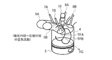
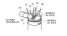
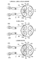
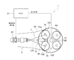
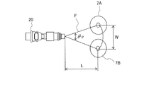
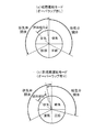
まず、図1〜22を参照して、本発明に係る内燃機関の制御装置の実施例1について詳細に説明する。図1及び図2は、上記する実施例1が適用される内燃機関の基本構成を示したものであり、図1はその内燃機関全体の縦断面図、図2は内燃機関の燃料噴射部分の模式的な拡大上部平面図を示したものである。なお、以下で述べる実施例1〜4では、内燃機関が備える単一の気筒を抽出して説明するが、それらの実施例は、単気筒及び多気筒の内燃機関に適用することができる。

次に、図21及び図22を参照して、本発明に係る内燃機関の制御装置の実施例2について詳細に説明する。なお、同図において実施例1と同様の構成については、同じ符号を付して示している。
次に、図23及び図24を参照して、本発明に係る内燃機関の制御装置の実施例3について詳細に説明する。なお、同図において実施例1,2と同様の構成については、同じ符号を付して示している。
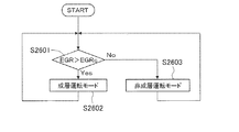
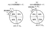
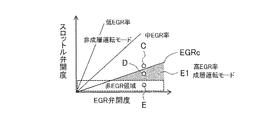
そこで、図25〜31を参照して、本発明に係る内燃機関の制御装置をEGR運転時へ適用した場合の実施例4について詳細に説明する。なお、本実施例4では、図1〜3に示した実施例1と同様の構成を備えた内燃機関1を使用して説明するが、その実施例1に代えて実施例2,3を適用することもできる。また、本実施例4においても実施例1と同様の構成については、同じ符号を付して説明する。
Claims (19)
- 2つの吸気開口部を有する気筒と、該気筒に接続され、前記2つの吸気開口部を介して前記気筒の燃焼室とそれぞれ連通される2つの吸気通路と、該2つの吸気通路内にそれぞれ配されて前記吸気開口部を開閉する2つの吸気弁と、前記2つの吸気通路内に燃料を噴射する1つ以上の燃料噴射弁とを備える内燃機関の制御装置であって、
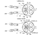
前記燃料噴射弁は、噴射される噴霧燃料の噴射方向が前記2つの吸気弁の中心よりも該2つの吸気弁の中心を結ぶ線分の中点寄りに設定され、
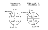
前記制御装置は、少なくとも排気行程内で燃料噴射を終了する成層運転モードと、圧縮行程から排気行程までの間で燃料噴射を終了する非成層運転モードとで、前記燃料噴射弁の噴射時期を制御しており、
前記成層運転モードにおける前記燃料噴射弁の噴射終了時期は、該燃料噴射弁の燃料噴射期間が該成層運転モードと同じ若しくはそれよりも短い前記非成層運転モードにおける前記燃料噴射弁の噴射終了時期よりも相対的に遅いことを特徴とする内燃機関の制御装置。 - 前記燃料噴射弁は2つであって、2つの該燃料噴射弁からそれぞれ異なる吸気通路内に前記燃料が噴射されることを特徴とする請求項1に記載の内燃機関の制御装置。
- 前記燃料噴射弁は、該燃料噴射弁から2つの噴射方向に噴霧燃料を噴射し、前記2つの噴射方向に噴射された噴霧燃料がそれぞれ異なる吸気通路内に供給されることを特徴とする請求項1に記載の内燃機関の制御装置。
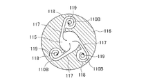
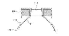
- 前記燃料噴射弁は、該燃料噴射弁が備える複数の噴口から旋回した燃料を噴射する噴射ノズルを有することを特徴とする請求項1〜3のいずれかに記載の内燃機関の制御装置。
- 燃料噴射弁から噴射される噴霧燃料の噴口での軸方向平均速度をV、ザウタ平均粒径をd、噴口から吸気弁までの距離をL、液相燃料密度をρ、空気粘性係数をμとしたときに、これらで定義されるストークス数St=ρd2V/(18μL)が1以下であることを特徴とする請求項1〜4のいずれかに記載の内燃機関の制御装置。
- 点火時期が圧縮行程上死点以降の場合には、成層運転モードで前記燃料噴射弁を制御することを特徴とする請求項1〜5のいずれかに記載の内燃機関の制御装置。
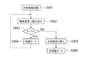
- 内燃機関暖機時には成層運転モードとすると共に点火時期を圧縮行程上死点以降にし、内燃機関暖機終了時には非成層運転モードとすると共に前記点火時期を圧縮行程上死点より早くすることを特徴とする請求項1〜5のいずれかに記載の内燃機関の制御装置。
- 前記内燃機関の冷却水温度、排気温度、触媒温度の少なくともいずれか1つが所定の温度よりも低い場合には成層運転モードとすると共に点火時期を圧縮行程上死点以降にし、前記内燃機関の冷却水温度、排気温度、触媒温度の少なくともいずれか1つが所定の温度を越えた場合には非成層運転モードへ移行すると共に前記点火時期を圧縮行程上死点より早くすることを特徴とする請求項1〜5のいずれかに記載の内燃機関の制御装置。
- 前記気筒の燃焼室内のEGR率が所定のEGR率より高い側に少なくとも成層運転モードを設け、前記気筒の燃焼室内のEGR率が所定のEGR率より低い側に少なくとも非成層運転モードを設けたことを特徴とする請求項1〜5のいずれかに記載の内燃機関の制御装置。
- 前記内燃機関の制御装置は、前記2つの吸気通路の上流部に設けられたスロットル弁と、前記2つの吸気通路と排気通路とを繋ぐEGR管を流れる排ガス流量を調整するためのEGR弁とをさらに備え、
前記スロットル弁の開度一定において、前記EGR弁開度が所定の開度より大きい側に少なくとも成層運転モードを設け、前記EGR弁開度が所定の開度より小さい側に少なくとも非成層運転モードを設けたことを特徴とする請求項1〜5のいずれかに記載の内燃機関の制御装置。 - 前記内燃機関の制御装置は、前記2つの吸気通路の上流部に設けられたスロットル弁と、前記2つの吸気通路と排気通路とを繋ぐEGR管を流れる排ガス流量を調整するためのEGR弁とをさらに備え、
前記EGR弁の開度一定において、前記スロットル弁開度が所定の開度より小さい側に少なくとも成層運転モードを設け、前記スロットル弁開度が所定の開度より大きい側に少なくとも非成層運転モードを設けたことを特徴とする請求項1〜5のいずれかに記載の内燃機関の制御装置。 - 前記成層運転モードにおいて、前記吸気弁の開弁開始時期を吸気上死点以降とすることを特徴とする請求項1〜11のいずれかに記載の内燃機関の制御装置。
- 前記成層運転モードにおいて、前記吸気弁の開弁開始時期を吸気上死点以降とし、前記非成層運転モードにおいて、前記吸気弁の開弁開始時期を吸気上死点以前とすることを特徴とする請求項1〜11に記載の内燃機関の制御装置。
- 2つの吸気開口部を有する気筒と、該気筒に接続され、前記2つの吸気開口部を介して前記気筒の燃焼室とそれぞれ連通される2つの吸気通路と、該2つの吸気通路内にそれぞれ配されて前記吸気開口部を開閉する2つの吸気弁と、前記2つの吸気通路内に燃料を噴射する1つ以上の燃料噴射弁とを備える内燃機関の制御装置であって、
前記燃料噴射弁は、噴射される噴霧燃料の噴射方向が前記2つの吸気弁の中心よりも該2つの吸気弁の中心を結ぶ線分の中点寄りに設定され、
前記制御装置は、吸気上死点前に燃料噴射が終了する同一噴射継続時間または同一噴射量における燃料噴射弁の噴射終了時期を、排気行程の後期と該排気行程の後期よりも進角時期に切り替えることで、前記燃料噴射弁の噴射時期を制御することを特徴とする内燃機関の制御装置。 - 前記燃料噴射弁の噴射終了時期を排気行程の後期にしたときに、前記吸気弁の開弁開始時期を排気弁の閉弁時期以降にすることを特徴とする請求項14に記載の内燃機関の制御装置。
- 前記燃料噴射弁の噴射終了時期を排気行程の後期より進角時期にしたときに、前記吸気弁の開弁開始時期を前記排気弁の閉弁時期よりも早くすることを特徴とする請求項15に記載の内燃機関の制御装置。
- 2つの吸気開口部を有する気筒と、該気筒に接続され、前記2つの吸気開口部を介して前記気筒の燃焼室とそれぞれ連通される2つの吸気通路と、該2つの吸気通路内にそれぞれ配されて前記吸気開口部を開閉する2つの吸気弁と、前記2つの吸気通路内に燃料を噴射する1つ以上の燃料噴射弁とを備える内燃機関であって、
前記燃料噴射弁は、噴射される噴霧燃料の噴射方向が前記2つの吸気弁の中心よりも該2つの吸気弁の中心を結ぶ線分の中点寄りに設定されていることを特徴とする内燃機関。 - 前記燃料噴射弁は2つであって、2つの該燃料噴射弁からそれぞれ異なる吸気通路内に前記燃料が噴射されることを特徴とする請求項17に記載の内燃機関。
- 前記燃料噴射弁は、該燃料噴射弁から2つの噴射方向に噴霧燃料を噴射し、前記2つの噴射方向に噴射された噴霧燃料がそれぞれ異なる吸気通路内に供給されることを特徴とする請求項17に記載の内燃機関。
Priority Applications (3)
| Application Number | Priority Date | Filing Date | Title |
|---|---|---|---|
| JP2011012294A JP2012154209A (ja) | 2011-01-24 | 2011-01-24 | 内燃機関の制御装置及び内燃機関 |
| CN2012100133339A CN102606329A (zh) | 2011-01-24 | 2012-01-17 | 内燃机的控制装置及内燃机 |
| US13/355,847 US20120191326A1 (en) | 2011-01-24 | 2012-01-23 | Control Device for Internal Combustion Engine and Internal Combustion Engine |
Applications Claiming Priority (1)
| Application Number | Priority Date | Filing Date | Title |
|---|---|---|---|
| JP2011012294A JP2012154209A (ja) | 2011-01-24 | 2011-01-24 | 内燃機関の制御装置及び内燃機関 |
Publications (2)
| Publication Number | Publication Date |
|---|---|
| JP2012154209A true JP2012154209A (ja) | 2012-08-16 |
| JP2012154209A5 JP2012154209A5 (ja) | 2013-03-14 |
Family
ID=46524022
Family Applications (1)
| Application Number | Title | Priority Date | Filing Date |
|---|---|---|---|
| JP2011012294A Pending JP2012154209A (ja) | 2011-01-24 | 2011-01-24 | 内燃機関の制御装置及び内燃機関 |
Country Status (3)
| Country | Link |
|---|---|
| US (1) | US20120191326A1 (ja) |
| JP (1) | JP2012154209A (ja) |
| CN (1) | CN102606329A (ja) |
Cited By (2)
| Publication number | Priority date | Publication date | Assignee | Title |
|---|---|---|---|---|
| WO2019225564A1 (ja) * | 2018-05-25 | 2019-11-28 | ヤマハ発動機株式会社 | エンジンユニット |
| JP2023178018A (ja) * | 2022-06-03 | 2023-12-14 | トヨタ自動車株式会社 | 内燃機関の制御装置 |
Families Citing this family (14)
| Publication number | Priority date | Publication date | Assignee | Title |
|---|---|---|---|---|
| JP5541535B2 (ja) * | 2011-09-13 | 2014-07-09 | 日立オートモティブシステムズ株式会社 | 内燃機関の燃料噴射制御装置 |
| US9650036B2 (en) * | 2012-05-04 | 2017-05-16 | Ford Global Technologies, Llc | Methods and systems for adjusting cylinder air charge |
| DE102013015011A1 (de) * | 2013-09-10 | 2015-03-12 | Daimler Ag | Brennkraftmaschine und zugehöriges Betriebsverfahren |
| DE102013014962A1 (de) * | 2013-09-10 | 2015-03-12 | Daimler Ag | Brennkraftmaschine und zugehöriges Betriebsverfahren |
| DE102013015010A1 (de) * | 2013-09-10 | 2015-03-26 | Daimler Ag | Brennkraftmaschine und zugehöriges Betriebsverfahren |
| DE102013014960A1 (de) * | 2013-09-10 | 2015-03-12 | Daimler Ag | Brennkraftmaschine und zugehöriges Betriebsverfahren |
| DE102013015012A1 (de) * | 2013-09-10 | 2015-03-12 | Daimler Ag | Brennkraftmaschine und zugehöriges Betriebsverfahren |
| JP6269410B2 (ja) * | 2014-09-18 | 2018-01-31 | トヨタ自動車株式会社 | 内燃機関の制御装置 |
| JP6332320B2 (ja) | 2016-04-11 | 2018-05-30 | トヨタ自動車株式会社 | 内燃機関の制御装置 |
| JP6134041B1 (ja) * | 2016-09-14 | 2017-05-24 | 三菱重工業株式会社 | エンジン及びエンジン制御方法 |
| JP6921569B2 (ja) * | 2017-03-21 | 2021-08-18 | 本田技研工業株式会社 | 燃料噴射制御装置 |
| JP6658663B2 (ja) * | 2017-04-25 | 2020-03-04 | トヨタ自動車株式会社 | 内燃機関の制御装置 |
| CN107525678B (zh) * | 2017-09-20 | 2023-08-29 | 西华大学 | 一种内燃机egr冷却器颗粒物沉积路径模拟试验装置及方法 |
| US11808232B2 (en) | 2022-02-02 | 2023-11-07 | Stanadyne Llc | High pressure port fuel injection system |
Citations (11)
| Publication number | Priority date | Publication date | Assignee | Title |
|---|---|---|---|---|
| JPH01195342A (ja) * | 1988-01-29 | 1989-08-07 | Hitachi Electron Eng Co Ltd | 溶媒中の微粒子の測定方法 |
| JPH07133752A (ja) * | 1993-11-08 | 1995-05-23 | Hitachi Ltd | 内燃機関の混合気形成装置 |
| JPH09264234A (ja) * | 1996-03-29 | 1997-10-07 | Mazda Motor Corp | エンジンの吸気装置 |
| JP2003503544A (ja) * | 1999-06-21 | 2003-01-28 | ザ、プロクター、エンド、ギャンブル、カンパニー | 不適当な大きさの粒子を再循環させる流動床グラニュレーターにおける顆粒洗剤の製造法 |
| JP2003239749A (ja) * | 2002-02-19 | 2003-08-27 | Nissan Motor Co Ltd | 内燃機関の燃料供給装置 |
| JP2006132546A (ja) * | 2006-02-09 | 2006-05-25 | Hitachi Ltd | 筒内噴射型内燃機関 |
| JP2007315383A (ja) * | 2006-04-24 | 2007-12-06 | Toyota Central Res & Dev Lab Inc | 火花点火式内燃機関 |
| JP2009192159A (ja) * | 2008-02-15 | 2009-08-27 | Mitsubishi Electric Corp | 空気調和機室内機 |
| JP2009216004A (ja) * | 2008-03-11 | 2009-09-24 | Toyota Motor Corp | 内燃機関 |
| JP2010127259A (ja) * | 2008-12-01 | 2010-06-10 | Nissan Motor Co Ltd | エンジンの始動時燃料噴射制御装置 |
| JP2010533583A (ja) * | 2007-07-16 | 2010-10-28 | ネーデルランツ オルガニサティー フォール トゥーゲパストナトゥールヴェテンシャッペリーク オンデルズーク テーエンオー | 材料を基板に塗布するための方法および器具 |
Family Cites Families (5)
| Publication number | Priority date | Publication date | Assignee | Title |
|---|---|---|---|---|
| JP3414303B2 (ja) * | 1998-03-17 | 2003-06-09 | 日産自動車株式会社 | 直噴火花点火式内燃機関の制御装置 |
| JP4023115B2 (ja) * | 2001-07-17 | 2007-12-19 | 日産自動車株式会社 | 直噴火花点火式エンジンの制御装置 |
| JP4483706B2 (ja) * | 2005-05-31 | 2010-06-16 | 日産自動車株式会社 | 筒内直接噴射式火花点火内燃機関の制御装置 |
| JP2008025400A (ja) * | 2006-07-19 | 2008-02-07 | Toyota Motor Corp | 筒内噴射式火花点火内燃機関の制御装置 |
| JP2008095652A (ja) * | 2006-10-16 | 2008-04-24 | Toyota Motor Corp | 筒内噴射式火花点火内燃機関の制御装置 |
-
2011
- 2011-01-24 JP JP2011012294A patent/JP2012154209A/ja active Pending
-
2012
- 2012-01-17 CN CN2012100133339A patent/CN102606329A/zh active Pending
- 2012-01-23 US US13/355,847 patent/US20120191326A1/en not_active Abandoned
Patent Citations (11)
| Publication number | Priority date | Publication date | Assignee | Title |
|---|---|---|---|---|
| JPH01195342A (ja) * | 1988-01-29 | 1989-08-07 | Hitachi Electron Eng Co Ltd | 溶媒中の微粒子の測定方法 |
| JPH07133752A (ja) * | 1993-11-08 | 1995-05-23 | Hitachi Ltd | 内燃機関の混合気形成装置 |
| JPH09264234A (ja) * | 1996-03-29 | 1997-10-07 | Mazda Motor Corp | エンジンの吸気装置 |
| JP2003503544A (ja) * | 1999-06-21 | 2003-01-28 | ザ、プロクター、エンド、ギャンブル、カンパニー | 不適当な大きさの粒子を再循環させる流動床グラニュレーターにおける顆粒洗剤の製造法 |
| JP2003239749A (ja) * | 2002-02-19 | 2003-08-27 | Nissan Motor Co Ltd | 内燃機関の燃料供給装置 |
| JP2006132546A (ja) * | 2006-02-09 | 2006-05-25 | Hitachi Ltd | 筒内噴射型内燃機関 |
| JP2007315383A (ja) * | 2006-04-24 | 2007-12-06 | Toyota Central Res & Dev Lab Inc | 火花点火式内燃機関 |
| JP2010533583A (ja) * | 2007-07-16 | 2010-10-28 | ネーデルランツ オルガニサティー フォール トゥーゲパストナトゥールヴェテンシャッペリーク オンデルズーク テーエンオー | 材料を基板に塗布するための方法および器具 |
| JP2009192159A (ja) * | 2008-02-15 | 2009-08-27 | Mitsubishi Electric Corp | 空気調和機室内機 |
| JP2009216004A (ja) * | 2008-03-11 | 2009-09-24 | Toyota Motor Corp | 内燃機関 |
| JP2010127259A (ja) * | 2008-12-01 | 2010-06-10 | Nissan Motor Co Ltd | エンジンの始動時燃料噴射制御装置 |
Cited By (3)
| Publication number | Priority date | Publication date | Assignee | Title |
|---|---|---|---|---|
| WO2019225564A1 (ja) * | 2018-05-25 | 2019-11-28 | ヤマハ発動機株式会社 | エンジンユニット |
| TWI741300B (zh) * | 2018-05-25 | 2021-10-01 | 日商山葉發動機股份有限公司 | 引擎單元 |
| JP2023178018A (ja) * | 2022-06-03 | 2023-12-14 | トヨタ自動車株式会社 | 内燃機関の制御装置 |
Also Published As
| Publication number | Publication date |
|---|---|
| CN102606329A (zh) | 2012-07-25 |
| US20120191326A1 (en) | 2012-07-26 |
Similar Documents
| Publication | Publication Date | Title |
|---|---|---|
| US7121253B2 (en) | Cylinder injection type internal combustion engine, control method for internal combustion engine, and fuel injection valve | |
| US20120191326A1 (en) | Control Device for Internal Combustion Engine and Internal Combustion Engine | |
| US5409169A (en) | Air-assist fuel injection system | |
| US6976468B2 (en) | Direct injection gasoline engine | |
| EP1389679B1 (en) | Compression ignition internal combustion engine | |
| JP3107489B2 (ja) | 内燃機関の混合気形成装置 | |
| US5148788A (en) | Air-assist fuel injection system | |
| US20140305402A1 (en) | Combustion Method and Internal Combustion Engine | |
| JPWO1999067514A1 (ja) | 筒内噴射型内燃機関および内燃機関の制御方法、燃料噴射弁 | |
| JP2010150971A (ja) | 火花点火式直噴エンジン | |
| JP2002206446A5 (ja) | ||
| JP2004100522A (ja) | 可変動弁装置を備えた内燃機関の燃料供給装置および方法 | |
| JP2007224753A (ja) | 火花点火式直噴エンジン | |
| JP2002202033A (ja) | 内燃機関の燃料噴射装置 | |
| JP4500790B2 (ja) | 直噴エンジン | |
| Ando et al. | Flow, mixture preparation and combustion in four-stroke direct-injection gasoline engines | |
| JP2011007046A (ja) | 直噴ガソリンエンジンの燃料噴射装置 | |
| JP2007187166A (ja) | 筒内噴射型内燃機関および内燃機関の制御方法、燃料噴射弁 | |
| JP3269282B2 (ja) | 直噴型火花点火式内燃機関 | |
| JP2007051549A (ja) | 燃料噴射弁及びそれを備えた筒内噴射式エンジン | |
| JP3181858B2 (ja) | 空気支援電磁燃料噴射弁 | |
| JP2882265B2 (ja) | 内燃機関の吸気装置 | |
| JP2006070862A (ja) | 筒内直接噴射式火花点火内燃機関 | |
| JP2010133360A (ja) | 内燃機関の吸気装置 | |
| JP2012241544A (ja) | 筒内噴射式エンジン及びその燃料噴射方法 |
Legal Events
| Date | Code | Title | Description |
|---|---|---|---|
| A521 | Written amendment |
Free format text: JAPANESE INTERMEDIATE CODE: A523 Effective date: 20130124 |
|
| A621 | Written request for application examination |
Free format text: JAPANESE INTERMEDIATE CODE: A621 Effective date: 20130124 |
|
| A977 | Report on retrieval |
Free format text: JAPANESE INTERMEDIATE CODE: A971007 Effective date: 20130425 |
|
| A131 | Notification of reasons for refusal |
Free format text: JAPANESE INTERMEDIATE CODE: A131 Effective date: 20130507 |
|
| A521 | Written amendment |
Free format text: JAPANESE INTERMEDIATE CODE: A523 Effective date: 20130705 |
|
| A131 | Notification of reasons for refusal |
Free format text: JAPANESE INTERMEDIATE CODE: A131 Effective date: 20130723 |
|
| A02 | Decision of refusal |
Free format text: JAPANESE INTERMEDIATE CODE: A02 Effective date: 20131015 |