JP2012154302A - Engine control of tractor - Google Patents
Engine control of tractor Download PDFInfo
- Publication number
- JP2012154302A JP2012154302A JP2011016713A JP2011016713A JP2012154302A JP 2012154302 A JP2012154302 A JP 2012154302A JP 2011016713 A JP2011016713 A JP 2011016713A JP 2011016713 A JP2011016713 A JP 2011016713A JP 2012154302 A JP2012154302 A JP 2012154302A
- Authority
- JP
- Japan
- Prior art keywords
- engine
- engine speed
- output
- mode
- speed
- Prior art date
- Legal status (The legal status is an assumption and is not a legal conclusion. Google has not performed a legal analysis and makes no representation as to the accuracy of the status listed.)
- Pending
Links
- 239000000446 fuel Substances 0.000 claims abstract description 97
- 238000012423 maintenance Methods 0.000 claims abstract description 19
- 230000008929 regeneration Effects 0.000 claims description 24
- 238000011069 regeneration method Methods 0.000 claims description 24
- 230000007704 transition Effects 0.000 claims description 19
- 238000000034 method Methods 0.000 claims description 7
- 230000008569 process Effects 0.000 claims description 7
- 238000001514 detection method Methods 0.000 claims 1
- 230000001965 increasing effect Effects 0.000 abstract description 8
- 230000005540 biological transmission Effects 0.000 description 43
- 239000007789 gas Substances 0.000 description 21
- 238000002347 injection Methods 0.000 description 17
- 239000007924 injection Substances 0.000 description 17
- 230000007423 decrease Effects 0.000 description 12
- 230000008859 change Effects 0.000 description 7
- 238000010586 diagram Methods 0.000 description 6
- 238000012805 post-processing Methods 0.000 description 6
- 230000008878 coupling Effects 0.000 description 5
- 238000010168 coupling process Methods 0.000 description 5
- 238000005859 coupling reaction Methods 0.000 description 5
- 230000003028 elevating effect Effects 0.000 description 5
- 239000003054 catalyst Substances 0.000 description 4
- 239000002828 fuel tank Substances 0.000 description 4
- 239000003921 oil Substances 0.000 description 4
- 230000003647 oxidation Effects 0.000 description 4
- 238000007254 oxidation reaction Methods 0.000 description 4
- 230000009467 reduction Effects 0.000 description 4
- 230000035939 shock Effects 0.000 description 4
- 230000008021 deposition Effects 0.000 description 3
- 230000007935 neutral effect Effects 0.000 description 3
- MWUXSHHQAYIFBG-UHFFFAOYSA-N nitrogen oxide Inorganic materials O=[N] MWUXSHHQAYIFBG-UHFFFAOYSA-N 0.000 description 3
- 238000003860 storage Methods 0.000 description 3
- 230000001133 acceleration Effects 0.000 description 2
- 238000009825 accumulation Methods 0.000 description 2
- 230000009471 action Effects 0.000 description 2
- QVGXLLKOCUKJST-UHFFFAOYSA-N atomic oxygen Chemical compound [O] QVGXLLKOCUKJST-UHFFFAOYSA-N 0.000 description 2
- 238000002485 combustion reaction Methods 0.000 description 2
- 230000001276 controlling effect Effects 0.000 description 2
- 239000008187 granular material Substances 0.000 description 2
- 239000004973 liquid crystal related substance Substances 0.000 description 2
- 239000000463 material Substances 0.000 description 2
- 238000002156 mixing Methods 0.000 description 2
- 239000001301 oxygen Substances 0.000 description 2
- 229910052760 oxygen Inorganic materials 0.000 description 2
- 230000001105 regulatory effect Effects 0.000 description 2
- 101150008604 CAN1 gene Proteins 0.000 description 1
- 101150063504 CAN2 gene Proteins 0.000 description 1
- 240000007594 Oryza sativa Species 0.000 description 1
- 235000007164 Oryza sativa Nutrition 0.000 description 1
- 229910000831 Steel Inorganic materials 0.000 description 1
- 230000005856 abnormality Effects 0.000 description 1
- 230000001174 ascending effect Effects 0.000 description 1
- 238000005452 bending Methods 0.000 description 1
- 238000004891 communication Methods 0.000 description 1
- 239000002826 coolant Substances 0.000 description 1
- 239000000498 cooling water Substances 0.000 description 1
- 238000005336 cracking Methods 0.000 description 1
- 238000005520 cutting process Methods 0.000 description 1
- 230000003247 decreasing effect Effects 0.000 description 1
- 230000000994 depressogenic effect Effects 0.000 description 1
- 230000006866 deterioration Effects 0.000 description 1
- 230000000694 effects Effects 0.000 description 1
- 238000005516 engineering process Methods 0.000 description 1
- 238000004880 explosion Methods 0.000 description 1
- 239000003502 gasoline Substances 0.000 description 1
- 238000003306 harvesting Methods 0.000 description 1
- 238000003780 insertion Methods 0.000 description 1
- 230000037431 insertion Effects 0.000 description 1
- 239000010687 lubricating oil Substances 0.000 description 1
- 238000013507 mapping Methods 0.000 description 1
- 230000007246 mechanism Effects 0.000 description 1
- 238000012544 monitoring process Methods 0.000 description 1
- 239000010705 motor oil Substances 0.000 description 1
- 238000013021 overheating Methods 0.000 description 1
- 230000002093 peripheral effect Effects 0.000 description 1
- 239000004033 plastic Substances 0.000 description 1
- 238000003825 pressing Methods 0.000 description 1
- 238000012545 processing Methods 0.000 description 1
- 238000005086 pumping Methods 0.000 description 1
- 230000001172 regenerating effect Effects 0.000 description 1
- 235000009566 rice Nutrition 0.000 description 1
- 239000000779 smoke Substances 0.000 description 1
- 239000004071 soot Substances 0.000 description 1
- 239000010959 steel Substances 0.000 description 1
- 239000000126 substance Substances 0.000 description 1
- 238000011144 upstream manufacturing Methods 0.000 description 1
- XLYOFNOQVPJJNP-UHFFFAOYSA-N water Substances O XLYOFNOQVPJJNP-UHFFFAOYSA-N 0.000 description 1
Images


Landscapes
- Control Of Vehicle Engines Or Engines For Specific Uses (AREA)
- Processes For Solid Components From Exhaust (AREA)
- Combined Controls Of Internal Combustion Engines (AREA)
Abstract
【課題】本発明では、エンジン出力モードの切換を行わなくても自動的に作業形態に応じたエンジン出力モードが選択されて、作業中にエンジンストップに至ることが無いようにする。
【解決手段】エンジンの出力をエンジン回転数の変動で出力変動するエンジン回転数変動制御モードと、負荷が増大してもエンジン回転数を一定に維持するエンジン回転数維持制御モードと、エンジン回転数維持制御に加え負荷限界近くになると回転数を上昇させて出力を上げる重負荷モードを備え、さらに標準出力カーブと低燃費出力カーブを選択可能にしたトラクタのエンジン制御において、左右の走行装置を各別に制動する左右ブレーキペダルを一体に連結したことを検出する連結センサを設け、該連結センサの連結信号の検出で、エンジン回転数変動制御モードと低燃費出力カーブを選択して制御すべくしたことを特徴とするトラクタのエンジン制御とする。
【選択図】図6In the present invention, an engine output mode corresponding to a work mode is automatically selected without switching the engine output mode so that the engine is not stopped during the work.
An engine speed fluctuation control mode in which the output of the engine fluctuates due to fluctuations in the engine speed, an engine speed maintenance control mode in which the engine speed remains constant even when the load increases, and an engine speed In addition to maintenance control, it has a heavy load mode in which the output is increased by increasing the number of revolutions when approaching the load limit.In addition, in the tractor engine control that allows selection of the standard output curve and fuel efficiency output curve, Separately, a connection sensor that detects that the left and right brake pedals to be braked are integrally connected is provided, and the engine speed fluctuation control mode and the low fuel consumption output curve are selected and controlled by detecting the connection signal of the connection sensor. The engine control of the tractor characterized by
[Selection] Figure 6
Description
本発明は、農作業機のトラクタにおけるエンジン制御に関する。 The present invention relates to engine control in a tractor of an agricultural machine.
所定のパワーを確保するスタンダードモードのエンジン出力トルクカーブとスタンダードモードより燃料消費量を低減させる燃料消費量低減モードのエンジン出力トルクカーブを設け、モード切換手段でスタンダードモードか燃料消費量低減モードを選択できるようにしたエンジン出力制御の技術が有る。 An engine output torque curve in standard mode that secures a predetermined power and an engine output torque curve in fuel consumption reduction mode that reduces fuel consumption compared to standard mode are provided, and the mode switching means selects either standard mode or fuel consumption reduction mode There is an engine output control technology that can be used.
作業機の走行は、駆動負荷が軽い路上の移動走行や駆動負荷が重い耕耘作業走行などエンジン負荷が変動するので、走行形態に応じてエンジン出力モードを切換える必要性が多いが、ついエンジン出力モードの切り替えを怠って、燃料消費量低減モードのままで重負荷作業を行って、走行負荷の急増によってエンジンストップに至ることが有る。 Since the engine load fluctuates, such as traveling on a road with a light driving load and tilling work driving with a heavy driving load, it is often necessary to switch the engine output mode according to the driving mode. If the switch is neglected, the heavy load operation is performed in the fuel consumption reduction mode, and the engine may be stopped due to a sudden increase in traveling load.
そこで、本発明では、エンジン出力モードの切換を行わなくても自動的に作業形態に応じたエンジン出力モードが選択されて、作業中にエンジンストップに至るようなことが無いようにすることを課題とする。 Therefore, in the present invention, an engine output mode corresponding to a work form is automatically selected without switching the engine output mode so that the engine is not stopped during the work. And
上記本発明の課題は、次の技術手段により解決される。
請求項1に記載の発明は、エンジンEの出力をエンジン回転数の変動で出力変動するエンジン回転数変動制御モードAと、負荷が増大してもエンジン回転数を一定に維持するエンジン回転数維持制御モードBと、エンジン回転数維持制御に加え負荷限界近くになると回転数を上昇させて出力を上げる重負荷モードCを備え、さらに標準出力カーブNと低燃費出力カーブSを選択可能にしたトラクタのエンジン制御において、左右の走行装置17,18を各別に制動する左右ブレーキペダル102R,102Lを一体に連結したことを検出する連結センサ103を設け、該連結センサ103の連結信号の検出で、エンジン回転数変動制御モードAと低燃費出力カーブSを選択して制御すべくしたことを特徴とするトラクタのエンジン制御とする。
The problems of the present invention are solved by the following technical means.
According to the first aspect of the present invention, the engine speed fluctuation control mode A in which the output of the engine E is fluctuated by the fluctuation of the engine speed, and the engine speed maintenance that maintains the engine speed constant even when the load increases. In addition to the control mode B and engine speed maintenance control, the tractor is equipped with a heavy load mode C that increases the engine speed and increases the output when approaching the load limit, and further allows the standard output curve N and the low fuel consumption output curve S to be selected. In the engine control, a
この構成で、路上や圃場を単に移動走行する場合には左右ブレーキペダル102R,Lを一体に連結して一体のブレーキペダルとして走行を制御するので、この左右ブレーキペダル102R,Lの連結を連結センサ103で検出することで、エンジン回転数変動制御モードAと低燃費出力カーブSとなって、エンジンEの軽負荷状態を燃料消費が少なく左右ブレーキペダルの踏込みによる走行速度の抑制が素早く効いて安全に走行できる。
With this configuration, when the vehicle simply travels on the road or in the field, the left and
請求項2に記載の発明は、標準出力カーブNと低燃費出力カーブSを選択可能にしたトラクタのエンジン制御において、アクセル変更手段146のアクセル開度Oに標準出力モード移行開度O2と、該標準出力モード移行開度O2より小さな低燃費出力モード移行開度O1を設け、低燃費出力カーブSでアクセル開度Oが標準出力モード移行開度O2に達すると標準出力カーブNを選択し、低燃費出力モード移行開度O1以下が所定時間T持続すると低燃費出力カーブSを選択して制御すべくしたことを特徴とするトラクタのエンジン制御とする。
In the engine control of the tractor in which the standard output curve N and the low fuel consumption output curve S can be selected, the invention according to
この構成で、エンジンEの出力を大きくするためにアクセル変更手段146でアクセルを大きく開くと直ちに標準出力カーブNとなって出力を増大し、アクセル変更手段146がアクセルと小さくして出力を抑える状態を低燃費出力モード移行開度O1以下になった状態が所定時間T持続すると低燃費出力カーブSで燃料消費を少なくする。
In this configuration, when the accelerator changing
請求項3に記載の発明は、エンジンEの排気を処理するDPF172bを設け、このDPF172bの再生処理を標準出力カーブNでのみ実施するようにしたことを特徴とする請求項1或いは請求項2に記載のトラクタのエンジン制御とした。
According to a third aspect of the present invention, the
この構成で、高出力でエンジンEが高温になっている状態でDPF172bを高温にする再生処理を行うので、再生処理が迅速に行われる。
請求項4に記載の発明は、DPF172bの再生処理はエンジン回転数維持制御モードBで行うことを特徴とする請求項3に記載のトラクタのエンジン制御とした。
With this configuration, the regeneration process for increasing the temperature of the
The invention described in
この構成で、エンジンEに負荷のかかるDPF172bの再生処理がエンジン回転数維持制御モードBで行われることで、負荷の増大によるエンジン回転の低下を防ぐことが出来る。
With this configuration, the regeneration process of the
請求項1乃至請求項4の構成で、エンジンEの標準出力カーブNと低燃費出力カーブSによる出力切換を自動で的確に行われ、操縦時の作業者を操縦操作に集中させることが出来て、作業の安全性を確保出来る。
With the configuration of
以下、本発明の実施形態を図面に示す実施例を参照しながら説明する。
図1は、蓄圧式燃料噴射装置の全体構成図である。蓄圧式燃料噴射装置は、例えば、多気筒ディーゼル機関に適用されるものであるが、ガソリン機関でもよい。そして、蓄圧式燃料噴射装置は、燃料を適宜に制御する噴射圧力に蓄圧するコモンレール1と、このコモンレール1に取り付けられるレール圧センサ2と、燃料タンク3より汲み上げた燃料を加圧してコモンレール1に圧送する燃料高圧ポンプ4と、コモンレール1に蓄圧された高圧燃料をエンジンEのシリンダ5内に噴射する高圧インジェクタ6と、前記燃料高圧ポンプ4と高圧インジェクタ6やその他の動作を制御するエンジン制御装置(ECU)12等から構成される。
Hereinafter, embodiments of the present invention will be described with reference to examples shown in the drawings.
FIG. 1 is an overall configuration diagram of a pressure accumulation type fuel injection device. The accumulator type fuel injection device is applied to, for example, a multi-cylinder diesel engine, but may be a gasoline engine. The accumulator fuel injection device pressurizes the
このように、コモンレール1は、エンジンEの各シリンダ5へ噴射する燃料を、要求された出力に必要な圧力とするものである。
前記燃料タンク3内の燃料は吸入通路により燃料フィルタ7を介してエンジンEで駆動される燃料高圧ポンプ4に吸入され、この燃料高圧ポンプ4によって加圧された高圧燃料は吐出通路8によりコモンレール1に導かれて蓄えられる。
Thus, the
The fuel in the fuel tank 3 is sucked into the fuel high-
コモンレール1内の高圧燃料は各高圧燃料供給通路9により気筒数分の高圧インジェクタ6に供給され、ECU12からの指令に基づき、高圧インジェクタ6が作動して、高圧燃料がエンジンEの各シルンダ5室内に噴射供給され、各高圧インジェクタ6での余剰燃料(リターン燃料)は各リターン通路10により共通リターン通路10aへ導かれ、この共通リターン通路10aによって燃料タンク3へ戻される。
The high-pressure fuel in the
また、コモンレール1内の燃料圧力(コモンレール圧)を制御するため燃料高圧ポンプ4に圧力制御弁11が設けられており、この圧力制御弁11はECU12からの信号によって、燃料高圧ポンプ4から燃料タンク3への余剰燃料の共通リターン通路10aの流路面積を調整するものであり、これによりコモンレール1側への燃料供給量を調整してコモンレール圧を制御することができる。
In addition, a
具体的には、エンジンEの運転条件に応じて目標コモンレール圧を設定し、レール圧センサ2により検出されるコモンレール圧が目標コモンレール圧と一致するよう、圧力制御弁11を介してコモンレール圧をフィードバック制御する構成としている。
Specifically, the target common rail pressure is set according to the operating condition of the engine E, and the common rail pressure is fed back via the
なお、圧力制御弁11を設けない制御では、アクセルを戻している間にアクセルの戻し程度に応じて高圧インジェクタ6の開きを調整して僅かな噴射を行うことでコモンレール圧を低下させて制御する。
In the control without the
さらに、アクセルの開度とエンジン回転の変化率でコモンレール圧を調整して適正なスピードで増速や減速を行うようにすることも出来る。
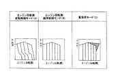
トラクタなどの農作業機におけるコモンレール1を有するディーゼルエンジンEのECU12は、図2に示すように、回転数と出力トルクの関係においてエンジン回転数変動制御モードAとエンジン回転数維持制御モードB及び重負荷モードCの三種類の制御モードを有する構成としている。
Furthermore, the common rail pressure can be adjusted by the accelerator opening and the rate of change of the engine rotation so as to increase or decrease the speed at an appropriate speed.
As shown in FIG. 2, the
エンジン回転数変動制御モードAは、エンジン回転数の変動で出力も変動するものである。基本的には移動走行する場合に使用するものであるが、急激なエンジンストールを防止するために作業中でも使用する。例えば、移動走行の場合は、ブレーキを掛けて走行速度を減速したり停止したりすると、走行負荷の増大に伴ってエンジン回転数が低下するため走行速度の減速や停止を安全に行うことができるものである。また、作業中においては、作業負荷が作用すると、負荷に応じてエンジン回転数が低下していくものである。 In the engine speed fluctuation control mode A, the output fluctuates due to the fluctuation of the engine speed. Basically, it is used when moving and running, but it is also used during work to prevent sudden engine stalls. For example, in the case of mobile travel, if the travel speed is reduced or stopped by applying a brake, the engine speed decreases as the travel load increases, so the travel speed can be safely reduced or stopped. Is. Further, during the work, when the work load is applied, the engine speed decreases according to the load.
エンジン回転数維持制御モードBは、負荷が増大してもエンジン回転数を一定に維持する制御である。基本的には作業を行う場合に使用するものである。例えば、トラクタであれば耕耘作業時に圃場が固く耕耘刃に抵抗が掛かるときなどであり、コンバインであれば収穫作業時に負荷が増大したときでも、回転数を維持するときなどである。 The engine speed maintaining control mode B is control for maintaining the engine speed constant even when the load increases. Basically, it is used when working. For example, the tractor is when the field is hard during the plowing operation and resistance is applied to the plowing blade, and the combine is when the rotation speed is maintained even when the load is increased during the harvesting operation.
重負荷モードCは、エンジン回転数維持制御モードBと同様に負荷が変動してもエンジン回転数を一定に維持する制御に加え、負荷限界近くになると回転数を上昇させて出力を上げる重負荷制御を加えた制御である。特に、負荷限界近くで作業を行う場合に使用するものである。例えば、トラクタで耕耘作業を行っている際に、特に、固い耕地に遭遇してもエンジン出力が通常の限界を越えて増大するので作業を中断することがなく、効率の良い作業が可能となる。 In the heavy load mode C, in addition to the control for maintaining the engine speed constant even when the load fluctuates, as in the engine speed maintenance control mode B, the heavy load mode C increases the engine speed to increase the output when the load is close to the load limit. This is a control with added control. In particular, it is used when working near the load limit. For example, when plowing work with a tractor, the engine output increases beyond the normal limit even when encountering hard cultivated land, so work can be performed efficiently without interruption. .
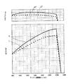
図3は、エンジンEの出力特性を表わす回転数と出力の関係図である。
低燃費出力カーブSと標準出力カーブNは、エンジン回転数(rpm)と出力(kw)との関係を示している。
FIG. 3 is a graph showing the relationship between the rotational speed and the output representing the output characteristics of the engine E.
The low fuel consumption output curve S and the standard output curve N show the relationship between the engine speed (rpm) and the output (kw).
低燃費出力カーブSは、標準出力カーブNの燃料消費率よりも燃料供給量を低下させた制御で、この低燃費出力カーブSは、全回転域で出力が標準出力カーブNよりも出力が1割程度低下する。 The low fuel consumption output curve S is a control in which the fuel supply amount is lower than the fuel consumption rate of the standard output curve N. This low fuel consumption output curve S has an output that is 1 higher than the standard output curve N in the entire rotation range. Decrease by about 10%.
符号STは、低燃費出力カーブSのときのエンジン回転数(rpm)とトルク(N・m)との関係を示しており、符号NTは、標準出力カーブNのときのエンジン回転数(rpm)とトルク(N・m)との関係を示している。 The symbol ST indicates the relationship between the engine speed (rpm) and the torque (N · m) at the time of the low fuel consumption output curve S, and the symbol NT indicates the engine speed (rpm) at the standard output curve N. And the torque (N · m).
低燃費出力カーブSと標準出力カーブNを切り換えてエンジンEを使用するには、モード選択手段(以下、エンジンパワー選択スイッチという)134を操作して設定する。エンジンパワー選択スイッチは、図6と図9に示している。 In order to use the engine E by switching between the low fuel consumption output curve S and the standard output curve N, the mode selection means (hereinafter referred to as the engine power selection switch) 134 is operated and set. The engine power selection switch is shown in FIGS.
トラクタが走行するときにはエンジン回転数変動制御モードAに自動的に切換える。そして、前記エンジンパワー選択スイッチ134で標準出力カーブNを選択し、トラクタに装着した作業機を駆動するPTO駆動手段(以下、PTO駆動スイッチという)151の入り状態が共に有効にされることで、エンジン回転数維持制御モードBに自動的に切換える構成とする。PTO駆動手段については、レバーなどの操作をスイッチ等で検出する構成としてもよい。
When the tractor travels, it automatically switches to the engine speed fluctuation control mode A. Then, the standard output curve N is selected by the engine
前記エンジンパワー選択スイッチ134で低燃費出力カーブSを選択し、作業機を駆動するPTO駆動スイッチ151の入り状態が共に有効にされることで、エンジン回転数変動制御モードAに自動的に切換えるように構成する。
By selecting the low fuel consumption output curve S with the engine
エンジンパワー選択スイッチ134で標準出力カーブNを選択して、PTO駆動スイッチ151を入り状態としての作業中は、自動的にエンジン回転数維持制御モードBでエンジン回転数制御を行う。そして、エンジン負荷に余裕があると判断すると、モード選択手段134で低燃費出力カーブSを選択するが、この選択で自動的にエンジン回転数変動制御モードAに切換わる。
While the engine
エンジンパワー選択スイッチ134で低燃費出力カーブSを選択し、PTO駆動スイッチ151を入り状態としての作業中は、自動的にエンジン回転数変動制御モードAでエンジン回転数制御を行う。そして、エンジン負荷に余裕が無いと判断すると、エンジンパワー選択スイッチ134で標準出力カーブNを選択するが、この選択で自動的にエンジン回転数維持制御モードBに切換わる。
While the engine
低燃費出力カーブSの許容最大負荷は、標準出力カーブNの許容最大負荷よりも低いので、許容最大負荷に達する可能性が高い。このため、仮に低燃費出力カーブSの選択状態において、エンジン回転数維持制御モードBで作業を行う場合において許容最大負荷に達すると、一気にエンジンストールしてしまうという不具合が発生する。 Since the allowable maximum load of the low fuel consumption output curve S is lower than the allowable maximum load of the standard output curve N, there is a high possibility that the allowable maximum load will be reached. For this reason, if the allowable maximum load is reached when working in the engine speed maintenance control mode B in the selected state of the low fuel consumption output curve S, there is a problem that the engine stalls at once.
そこで、低燃費出力カーブSとエンジン回転数変動制御モードAで作業を行うと、負荷の作用に応じてエンジン回転数が低下していくので、一気にエンジン回転数がストールしてしまって、エンジンを再始動しなくてはならないという不具合を防止できるようになる。また、負荷に応じてエンジン回転数が低下していくので、作業者は負荷の状態を容易に把握し易くなる。 Therefore, when working in the low fuel consumption output curve S and the engine speed fluctuation control mode A, the engine speed decreases according to the action of the load. The problem of having to restart can be prevented. Further, since the engine speed decreases according to the load, the operator can easily grasp the state of the load.
また、エンジンパワー選択スイッチ134で標準出力カーブNを選択し、作業機を駆動するPTO駆動スイッチ151の入り状態が共に有効にされることで、自動的にエンジン回転数維持制御モードBに切換えるように構成したので、エンジン自体が持っている許容最大負荷まで一定の回転数で作業できるので、エンジン自体の能力を最大に引き出して、作業能率を向上させることができるようになる。
Further, when the standard output curve N is selected by the engine
前記PTO駆動スイッチ151を入り状態にすると、後述する図6に示すPTOクラッチsol(ソレノイド)54bに通電して、図5に示すPTOクラッチ54aが入りとなる。
When the
また、図6に示すように、特定のエンジン回転数を記憶するエンジン回転数記憶手段(以下、エンジン回転数記憶スイッチという)152と、記憶している特定のエンジン回転数を再現するエンジン回転数再現手段(以下、エンジン回転数再現スイッチという)153を設ける構成とする。このエンジン回転数再現スイッチ153を設けることで、特定のエンジン回転数に自動的に設定できるので、アクセルレバーなどの操作が不要となり、操作性が向上するようになる。
Further, as shown in FIG. 6, an engine speed storage means (hereinafter referred to as an engine speed storage switch) 152 for storing a specific engine speed, and an engine speed for reproducing the stored specific engine speed. Reproduction means (hereinafter referred to as an engine speed reproduction switch) 153 is provided. By providing the engine
そして、エンジンパワー選択スイッチ134で低燃費出力カーブSを選択し、エンジン回転数再現スイッチ152の入り状態が共に有効にされることで、自動的にエンジン回転数変動制御モードAに切換えるように構成する。
The engine
エンジン回転数記憶スイッチ152で、作業者が希望する特定のエンジン回転数を走行制御装置120に記憶する。そして、エンジン回転数再現スイッチ153を操作して、記憶しているエンジン回転数を再現する。このように、エンジン回転数再現スイッチ153で記憶している特定のエンジン回転数を再現する場合は、作業を行う場合である。記憶しているエンジン回転数を再現すると共に、エンジンパワー選択スイッチ134で低燃費出力カーブSを選択すると、自動的にエンジン回転数変動制御モードAに切換わる。
The engine
このように、作業を行う際において、記憶しているエンジン回転数を再現すると共に、エンジンパワー選択スイッチ134で低燃費出力カーブSを選択すると、自動的にエンジン回転数変動制御モードAに切換わるように構成したので、負荷の作用に応じてエンジン回転数が低下していくので、一気にエンジン回転数がストールしてしまって、エンジンを再始動しなくてはならないという不具合を防止できるようになる。また、負荷に応じてエンジン回転数が低下していくので、作業者は負荷の状態を容易に把握し易くなる。
As described above, when the work is performed, the stored engine speed is reproduced, and when the low fuel consumption output curve S is selected by the engine
また、自動制御として、作業機を駆動するPTO出力軸54c(図5)の負荷率を検出し、一定時間標準出力カーブNで負荷率略70%以下で作業、又は走行している場合には、自動的に低燃費出力カーブSに切り換えるように構成する。これにより、効率の良い低燃費の作業や走行を行うことができるようになる。
Further, as automatic control, when the load factor of the
逆に、一定時間低燃費出力カーブSで負荷率略70%以上で作業、又は走行している場合には、自動的に標準出力カーブNに切換るように構成する。PTO出力軸54cの負荷率は、規定の回転数に対する現在の回転数から算出する。
Conversely, when the vehicle is operating or running at a load factor of approximately 70% or more in the low fuel consumption output curve S for a certain period of time, the standard output curve N is automatically switched. The load factor of the
また、走行変速レバー(図示せず)を路上走行位置(高変速位置で高速走行をする位置)にするか、又は標準出力カーブNで一定時間(10分程度)走行すると、自動的に低燃費出力カーブSに切換るようにしても良い。 In addition, when a travel shift lever (not shown) is set to a travel position on the road (a position at which high speed travels at a high shift position) or travels for a certain time (about 10 minutes) on a standard output curve N, fuel efficiency is automatically reduced. You may make it switch to the output curve S.
前記エンジン回転数変動制御モードAとエンジン回転数維持制御モードB、及び重負荷モードCにおいて、農作業車(トラクタ、コンバイン、田植機等)の走行変速レバーの変速操作、又は作業クラッチ(トラクタであればロータリ駆動等のPTOクラッチであり、コンバインであれば刈取部や脱穀部の駆動クラッチである)の入り切り操作等によって自動的にエンジン回転数維持制御モードBに切り替わるように構成してもよい。なお、トラクタでは、PTOクラッチが切りであっても、作業機を連結しているリフトアームが最上位置より低く、かつリフトアームを昇降させている場合には、プラウ作業やプラソイラ作業であるので、自動的にエンジン回転数維持制御モードBや重負荷モードCにする。 In the engine speed fluctuation control mode A, the engine speed maintenance control mode B, and the heavy load mode C, a shift operation of a traveling speed change lever of a farm vehicle (tractor, combine, rice transplanter, etc.) or a work clutch (whether it is a tractor) It may be configured to automatically switch to the engine speed maintenance control mode B by an on / off operation or the like of a PTO clutch for rotary drive or the like, and for a combine, a drive clutch for a reaping part or a threshing part. In the tractor, even if the PTO clutch is disengaged, if the lift arm connecting the work machine is lower than the uppermost position and the lift arm is raised and lowered, it is plow work or plastic work, The engine speed maintaining control mode B and heavy load mode C are automatically set.
また、エンジン回転数変動制御モードAとエンジン回転数維持制御モードB、及び重負荷モードCは、エンジン回転数制御モード切換スイッチ148(図6)の操作により、手動で切り換えるように構成してもよい。手動の場合は、運転者の判断で選択する。 Further, the engine speed fluctuation control mode A, the engine speed maintenance control mode B, and the heavy load mode C may be manually switched by operating the engine speed control mode changeover switch 148 (FIG. 6). Good. In the case of manual operation, the driver selects it.
また、副変速レバーを路上走行位置にすると、自動的にエンジン回転数変動制御モードAになるが、路上走行の場合には負荷が小さいので、自動的に低燃費出力カーブSとなるように構成してもよい。この場合に、副変速レバーを路上走行位置以外に変速操作すると、事前に標準出力カーブNを選択していれば、その標準出力カーブNに戻すように構成する。これにより、効率のよい走行が可能となる。 In addition, when the sub-shift lever is set to the road running position, the engine speed fluctuation control mode A is automatically set. However, in the case of road driving, the load is small, so the fuel efficiency output curve S is automatically set. May be. In this case, when the sub-shift lever is shifted to a position other than the on-road travel position, if the standard output curve N has been selected in advance, it is returned to the standard output curve N. Thereby, efficient driving | running | working is attained.
また、エンジンパワー選択スイッチ134が入り状態のときは、常にエンジン回転数変動制御モードAとしてもよい。また、エンジンパワー選択スイッチ134が切りであり、アクセルペダルの操作で自動的に変速を行う場合も、エンジン回転数変動制御モードAとしてもよい。
Further, when the engine
また、エンジンパワー選択スイッチ134が切りであり、手動スイッチ150(図6)を切りにし、さらに、PTOクラッチが入りであると、自動的にエンジン回転数維持制御モードBにしてもよい。このPTOクラッチが入りの条件の代わりに、作業機が下げ状態やエンジン回転数再現スイッチ153が入り状態であってもよい。そして、PTOクラッチが切りとなったり、作業機が上げ状態になったり、エンジン回転数再現スイッチ153が切り状態になると、自動的にエンジン回転数変動制御モードAにする構成とする。
Further, when the engine
前記手動スイッチ150が入り状態であれば、常にエンジン回転数維持制御モードBとする。これにより、能率のよい作業や走行が可能となる。
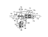
図10はエンジンのシリンダ5内への吸気と排気の模式図であり、4サイクルのディーゼルエンジンの実施例である。過給器TBの吸気タービン160により過給された空気は、エアクリーナ161から吸気タービン160、インタークーラー162を通過して吸気マニホールド163からシリンダ5内へ送られる構成である。164は吸気バルブであり、165はピストンである。166はカムでありロッカーアーム167を介して吸気バルブ164と排気バルブ168を開閉させるものである。
If the
FIG. 10 is a schematic diagram of intake and exhaust into the
シリンダ5内で燃焼した排ガスは、排気バルブ168から排気マニホールド42を通過した後、過給器TBの排気タービン169で過給器TBを駆動して排出される構成である。
The exhaust gas combusted in the
このディーゼルエンジンは、排気ガスの一部を吸気側に混入させるためのEGR(排気再循環装置)回路170を有している。EGR回路170で排気ガスの一部を吸気側に混入させることで酸素量(O2)を減らして、窒素酸化物NOxの発生を低減させるように構成している。ただし、EGR率が上昇しすぎると、逆に酸素量が少なくなって不完全燃焼になるので、燃焼状態によりEGR率を調節する必要がある。この調節は、EGRバルブ171にて行う。EGR回路170は、後述する後処理装置172下流側の排気管173と過給器TBの吸気タービン160上流側の吸入管174との間を接続している。また、EGR回路170の途中にはEGRクーラ175を設ける構成としている。このEGRバルブ171の開閉具合でシリンダ5内への排気ガスの還元量が変化する。
This diesel engine has an EGR (exhaust gas recirculation device) circuit 170 for mixing a part of the exhaust gas into the intake side. The EGR circuit 170 is configured to reduce the amount of oxygen (O 2) by mixing a part of the exhaust gas into the intake side, thereby reducing the generation of nitrogen oxides NOx. However, if the EGR rate increases too much, the amount of oxygen decreases and incomplete combustion occurs. Therefore, it is necessary to adjust the EGR rate according to the combustion state. This adjustment is performed by the
排気タービン169を通過後の排気ガスは、後処理装置172を通過してマフラー176から大気中に排出される。後処理装置172は、酸化触媒(DOC)172aとディーゼルパティキュレートフィルター(DPF)172bとから構成されている。
The exhaust gas that has passed through the
酸化触媒(DOC)172aは不燃物室を燃焼させるものであり、DPF172bは粒状化物質(PM)を捕集するためのものである。前記EGRバルブ171と絞り弁177については、ECU12により制御される構成である。後処理装置172はDPF172bのみで構成してもよい、酸化触媒(DOC)を設けると不燃物質が燃焼するので、よりクリーンな排気ガスとなる。
The oxidation catalyst (DOC) 172a burns the incombustible chamber, and the
DPF172bは、排気ガスの温度が低い状態(低負荷)が長時間続くと、PMが溜まってきて能力の低下が懸念される。そこで、後処理装置172の下手側に絞り弁177を設け、この絞り弁177を絞るとDPF172b内の圧力が高く保持されるので温度も高くなる。これにより、高い温度の影響により、DPF172bの再生が可能となる。即ち、高い温度の排気ガスがDPF172bを通過すると、DPF172b内に存在しているPMが焼き飛ばされることでDPF172bが再生される。
When the state of the exhaust gas is low (low load) continues for a long time, the
DPF172bを再生させるためのDPF再生運転としては、EGRバルブ171と絞り弁177の両方を絞る。そして、燃料噴射タイミングのリタード(遅角)と合わせてDPF172b内のガス温度を上昇させ、DPF172bが再生に入るようにする。これにより、燃料のアフター噴射(排気ガス温度を上昇させるため)が不要となったり、アフター噴射の回数を減らしたりすることができるようになるので、燃料消費量を抑制できて環境にもよい。
In the DPF regeneration operation for regenerating the
なお、トラクタでは、PTO軸の駆動タイミングでDPF再生運転を行い、PTO軸を長時間駆動しない場合に所定条件でDPF再生運転を行うようにしても良い。
このようなDPF再生運転を行うための条件としては、後処理装置172の上手側に圧力センサ178を設けておいて、この圧力センサ178での堆積予測値(圧力センサ178で検出する圧と温度センサ179が検出する温度によって推測した堆積予測値)が所定値以上になるとDPF172b内にPMが蓄積して抵抗となっている状態なので、DPF再生運転を行うようにする。堆積予測値はエンジン回転数に対する圧力をマップ化しておくことで、正確な堆積予測値を算出できる。
In the tractor, the DPF regeneration operation may be performed at the drive timing of the PTO shaft, and the DPF regeneration operation may be performed under a predetermined condition when the PTO shaft is not driven for a long time.
As a condition for performing such a DPF regeneration operation, a pressure sensor 178 is provided on the upper side of the
また、DPF再生運転に入った状態が長時間続くと、過熱状態となってしまいDPF172bが損傷してしまう。そこで、後処理装置172の下手側に温度センサ179を設け、この温度センサ179の値が所定値を超えるとDPF再生運転を止めて通常運転に戻るようにする。
In addition, if the state in which the DPF regeneration operation is started continues for a long time, an overheating state occurs and the
通常の運転は、EGRバルブ171と絞り弁177を同時に制御してEGR量を適宜コントロールするようにする。特に、絞り弁177を有することで、DPF172b内のガス温度を高く保持することができるようになる。
In normal operation, the
EGRバルブ171の開度が適正であるかは、エアクリーナ161に設けるエアーフローセンサと負圧センサで推測するEGRバルブ立を監視して行うが、正常範囲を越えると異常とエンジン制御装置12で判定し、警報や表示で作業者に注意を促す。
Whether or not the opening degree of the
前述のような構成としたことで、吸気スロットルが不要となる。即ち、過給器付き機関では吸気側圧力が高いので、EGRガス量を確保するために排気絞り弁または吸気スロットルを設け、EGRバルブと連動した制御が必要となるが、このようなシステムが不要となる。 With the configuration as described above, an intake throttle is not required. In other words, since the intake side pressure is high in an engine with a supercharger, an exhaust throttle valve or an intake throttle is required to secure the amount of EGR gas, and control in conjunction with the EGR valve is required, but such a system is unnecessary. It becomes.
また、DPF172b下流の排気ガスを取り出すために、過給器TBの汚れに伴う性能劣化を生じることを防止できるようになる。そして、EGRガスはEGRクーラ175で冷却されるため、NOx低減に対して効果が大きくなる。
Further, since the exhaust gas downstream of the
前述したように、DPFの再生運転を行なうDPF強制再生モードにおいては、排気絞り弁177を絞り、ON−OFF制御によってEGRバルブ171を全閉とするように構成する。したがって、排気ガスの還元が行なわれないのでNOが増加し、このNOが酸化触媒(DOC)172aによってNO2に転換され、DPF172bの再生が促進されるようになる。
As described above, in the DPF forced regeneration mode in which the DPF regeneration operation is performed, the
また、DPF172bの強制再生中において、エンジン回転がローアイドルに移行した場合は、前記EGRバルブ171を全開とする。DPF172bの下流側には温度センサ179を設けているので、この温度センサ179による検出値が所定値以上に上昇したことも条件に加えるようにしてもよい。
Further, when the engine rotation shifts to low idle during the forced regeneration of the
このようなDPF強制再生モードは、例えエンジンEの回転制御がエンジン回転数変動制御モードA中であっても回転制御をエンジン回転数維持制御モードBに切換えて行うことで、負荷が増加することによる回転低下を防ぐ。また、DPF強制再生モードには、低燃費出力カーブSでは入ることなく、標準出力カーブNの高負荷領域で排気温度が高い状態で入る。 In such a DPF forced regeneration mode, even if the rotation control of the engine E is in the engine speed fluctuation control mode A, the load is increased by switching the rotation control to the engine speed maintenance control mode B. Prevents rotation drop due to. Further, the DPF forced regeneration mode does not enter the low fuel consumption output curve S but enters the exhaust gas temperature high in the high load region of the standard output curve N.
また、走行停止状態でDPF強制再生モードを実施する場合は、後輪18をジャッキアップして浮かせ、エンジン駆動力をミッションケース16を介して後輪18に伝えて駆動負荷を加えることで、排気温度を上昇させる。
In addition, when the DPF forced regeneration mode is executed in the travel stop state, the
また、圧力センサ178で検出する圧と温度センサ179が検出する温度によって推測した堆積量でDPF172bに詰まりが生じた状態と判断されれば、変速段を最低速の一段で発進するよう制限することで、煤等の粒状化物質(PM)の発生を少なくする。
Further, if it is determined that the
低温時の始動性を良くするために、吸気マニホールド163への空気量を調整する吸気スロットルバルブを設け、始動時に吸気量を少なくすると冷たい空気によるシリンダ内の温度低下を防いで着火性を良くすることが出来る。また、旋回時にも負荷低下による排気ガス温度低下を防ぐために、吸気スロットルバルブで吸気量を絞るようにする。
In order to improve startability at low temperatures, an intake throttle valve that adjusts the amount of air to the
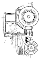
図4には、本発明を実施した作業車としてトラクタ15を示している。
トラクタ15は、機体前部のボンネット内にエンジンEを搭載し、このエンジンEの回転動力をミッションケース16内の変速装置に伝え、この変速装置で減速された回転動力を前輪17と後輪18とに伝えるようにしている。機体上の操縦席22の周りはキャビン19で覆われている。キャビン19の内部で操縦席22前側のメータパネル117を設けたダッシュボード13からステアリングハンドル20を立設し、その周りに前後進レバーや駐車ブレーキレバーやPTO変速レバー等を配置している。
FIG. 4 shows a
The
このエンジンEは、前記のコモンレール式のディーゼルエンジンで、近くにDOC172aとDPF172bを搭載し、DPF強制再生モードで高熱となるDPF172bは、エンジンE側に遮熱板を設けて、熱が伝わらないようにしている。
This engine E is a diesel engine of the above-described common rail type, and is equipped with a
また、エンジンEとDOC172aとDPF172bを収納したボンネットは、前側を支点にして跳ね上げて開放保持することで、メンテナンス作業を行い易くしている。
図11は、DPF172bの取付状態を示し、架台180の支え枠181a,181bに載せてスチールベルト182とテンションボルト185で固定している。架台180は規格品の角材を円弧状に切り欠いてDPF172bを載せるようにして製作を容易にしている。図12の如く、支え枠181a,181bの下に緩衝ゴム184を敷いてコ字状角材183の内側に取り付けることで、緩衝ゴム184に熱が伝わり難くしている。
Further, the bonnet containing the engine E, the
FIG. 11 shows an attached state of the
なお、DPF172bを車体フレームから吊り下げたバイメタル等の熱膨張率の大きい湾曲したブラケットで支持し、ボンネットカバーでDPF172bを押えるようにしても良い。
The
図13は、エンジンEへの過給器TBとDPF172bの取付状態で、過給器TBから出た排気ガスがDPF172bに曲がることなく直に流入するように配置して排気ガスの流れを良くしている。この構成で、排気管187にDOC172aを組み込む。
FIG. 13 shows a state in which the supercharger TB and the
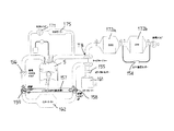
図14は、エンジンEの吸排気回路の別実施例で、過給器TBからインタークーラー162を介して吸気スロットバルブ156を経てシリンダ5に吸気する吸気回路にインタークーラー162を通さず吸気するバイパス吸気路157を設けて、DPF強制再生モード時にこのバイパス吸気路157と通してシリンダ5へ吸気するようにする。このことで、DPF172bの排気温度上昇を早くする。
FIG. 14 shows another embodiment of the intake / exhaust circuit of the engine E. Bypass intake passage for intake without passing through the
154はDPF172bの入口を出口の空気圧を検出するDPF差圧センサで、155はエアクリーナ161からの吸入空気圧を検出するエアーフローセンサで、バイパス吸気路157の入口に第一切換バルブ158を設け、出口に第二切換バルブ159を設けている。
A DPF
DPF差圧センサ154で検出するDPF172bの詰まりに応じて吸気スロットバルブ156を開いて、吸気量を調整して最適空燃比を確保する。
また、DPF172bの自動再生中に排気温度を高温にするために吸気スロットバルブ156を絞って吸気量を調整する。
The
Further, in order to increase the exhaust temperature during automatic regeneration of the
エアーフローセンサ155の故障は吸気効率マップとエアーフローセンサ155の校正流量にて行い、故障と判定すると、故障フラグを立ててマップを切換えて回転・吸気効率マップに手制御を行う。
The failure of the
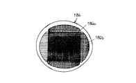
図15は、DPF172bの出口に設けるフィルタ186を示し、中心側フィルタ186aの目合いを周辺側フィルタ186bの目合いよりも細かくすることで、排気ガスの流れを周辺に導いてDPF再生時に周辺まで高温にして粒状物の焼却をフィルタ189の全体で行えるようにする。
FIG. 15 shows a
エンジンEの燃料噴射量制御において、300rpm以下の回転(クラッキング回転)でその他の噴射量よりも40%減少させると、初爆の着火遅れによるノックオンの増大を防止できる。 In the fuel injection amount control of the engine E, if the rotation is 300 rpm or less (cracking rotation) and is reduced by 40% from the other injection amounts, an increase in knock-on due to the ignition delay of the first explosion can be prevented.
また、始動時には1000rpmまではパイロット噴射を2回行い、1000rpmを越えるとパイロット噴射1回アフター噴射1回を行い、一旦回転が1000rpm以上になるとパイロット噴射1回アフター噴射1回にすることで、黒煙の発生を抑えられる。 In addition, at the time of start-up, pilot injection is performed twice up to 1000 rpm, once the engine speed exceeds 1000 rpm, one pilot injection is performed once, and once the rotation exceeds 1000 rpm, the pilot injection is performed once and the after-injection is performed once. Smoke generation can be suppressed.
また、エンジン制御として、前後進レバー操作位置センサ129や副変速レバー操作位置センサ130の変速段変更によって変速時にエンジン回転を一時的に低下させることで、変速ショックを和らげることが出来る。
Further, as engine control, the shift shock can be reduced by temporarily reducing the engine rotation at the time of shifting by changing the gear position of the forward / reverse lever
なお、駆動軸の駆動トルクを検出し、急激なトルク変動が起こらないように燃料噴射量を制御することも考えられる。
左右の後輪18,18の間にはヒッチ21と三点リンク(図示省略)を設けてロータリ等の作業機を装着するように構成している。
It is also conceivable to detect the drive torque of the drive shaft and control the fuel injection amount so that sudden torque fluctuation does not occur.
A
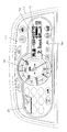
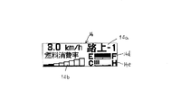
図7は、メータパネル117の拡大図である。図8は、メータパネル117内の液晶のデータ表示部14の拡大図であり、表示の一例を示している。図9は、ダッシュボード13に立設したステアリングハンドル20の右側周辺の拡大斜視図である。
FIG. 7 is an enlarged view of the
ステアリングハンドル20の前側のメータパネル117には、中央にエンジン回転計24を配置し、その右側に液晶のデータ表示部14を配置し、左側に省エネモニタランプ23を配置している。
The
データ表示部14には、現在の変速段を表示する変速段表示14aと、燃料消費率表示14b等が有り、燃料消費率表示14bは走行速度表示14cと一定時間毎に切り換わる構成である。燃料消費率とは、そのときのエンジン回転数における最大出力を出すための燃料噴射量に対する、実際に噴射されている燃料噴射量の割合のことである。また、データ表示部14には、燃料計14dとエンジンEの冷却水温計14eも表示する構成としている。
The
省エネモニタランプ23は、エンジンパワー選択スイッチ134で低燃費出力カーブSを選択しているときに点灯する構成であり、緑色に点灯する。
また、図9に示すように、ステアリングハンドル20の右側であって、ダッシュボード13にエンジンパワー選択スイッチ134を設けている。このエンジンパワー選択スイッチ134を押すと、エンジンが低燃費出力カーブSで制御される。
The energy saving
Further, as shown in FIG. 9, an engine
図5は、ミッションケース16内の変速装置の伝動機構を示す線図である。エンジンEから前輪17と後輪18への動力伝動構成を説明する。
エンジンEの出力軸に直結した入力軸25には、第一ギヤ26を固着し、前後進切換クラッチ27を装着している。
FIG. 5 is a diagram showing a transmission mechanism of the transmission in the
A
前後進切換クラッチ27の一方の第二ギヤ28は、第一変速軸29に固着した第三ギヤ30に噛み合って減速し、前後進切換クラッチ27の他方の第四ギヤ31は、カウンタギヤ32を介して第一変速軸29に固着した第五ギヤ33に噛み合っており、逆転で動力を伝動している。すなわち、前後進切換クラッチ27を第二ギヤ28側に入れる(繋ぐ)と、入力軸25の回転が逆方向回転で第一変速軸29に伝動され、第四ギヤ31側に入れると、入力軸25の回転が順方向回転で第一変速軸29に伝動され、第二ギヤ28と第四ギヤ31の両方から離れたニュートラル状態が、動力伝動を断ったメインクラッチ切状態である。油圧バルブの制御によって、このメインクラッチ切状態を保持出来るようにしている。すなわち、自動制御を行うときや、前後進レバーの操作時、そしてクラッチペダルの操作時において作動する前後進切換クラッチ27が、メインクラッチとして機能している構成である。
One
前後進切換クラッチ27の伝動下手側であって前記第一変速軸29には、一速/三速切換用第一変速クラッチ34と、二速/四速切換用第二変速クラッチ35を装着している。
一速/三速切換用第一変速クラッチ34の第一クラッチギヤ36と第二クラッチギヤ37は、第二カウンタ軸38に固着した第三クラッチギヤ39と第四クラッチギヤ40に噛み合っており、一速用にしたり三速用にしたりして、第一変速軸29の回転を第二カウンタ軸38に伝動している。
On the first transmission shaft 29 on the lower transmission side of the forward /
The first
さらに、二速/四速切換用第二変速クラッチ35の第五クラッチギヤ41と第六クラッチギヤ42は、第二カウンタ軸38に固着した第七クラッチギヤ43と第八クラッチギヤ44に噛み合っており、二速用にしたり四速用にしたりして、第一変速軸29の回転を第二カウンタ軸38に伝動している。
Further, the fifth
第二カウンタ軸38の伝動下手側に、第三カウンタ軸45をカップリング46で連結しており、回転をそのままで伝動している。この第三カウンタ軸45には、小ギヤ47と大ギヤ48を固着している。この小ギヤ47と大ギヤ48は、第二変速軸49に装着した高・低速切換クラッチ50のクラッチ大ギヤ51とクラッチ小ギヤ52にそれぞれ噛み合っており、第三カウンタ軸45の回転を高速又は低速で第二変速軸49に伝動している。
The
第二変速軸49の伝動下手側端部に第六ギヤ53を固着し、この第六ギヤ53は、第三駆動軸54に回動可能に軸支している大小ギヤ55部の大ギヤ56と噛み合っており減速伝動している。
A
大小ギヤ55部の小ギヤ57は、ベベルギヤ軸58に軸支した二連の副変速クラッチ59の第七ギヤ60に噛み合わせて減速伝動している。さらに、第七ギヤ60と一体に設けた第八ギヤ61を、第五カウンタ軸62に固着した第二大ギヤ63に噛み合わせて減速伝動している。
The small gear 57 of the large and
第五カウンタ軸62には、さらに第二小ギヤ64が固着され、この第二小ギヤ64がベベルギヤ軸58の第三大ギヤ65と噛み合ってさらに減速伝動されている。従って、第二変速軸49の回転は、第六ギヤ53→大ギヤ56→小ギヤ57→第七ギヤ60→第八ギヤ61→第二大ギヤ63→第二小ギヤ64→第三大ギヤ65と順次減速されながら伝動されていく。
A second
副変速レバーで操作される二連の副変速クラッチ59の第一シフター66と第二シフター67は、ベベルギヤ軸58へ軸方向にスライド可能に係合していて、第一シフター66を第七ギヤ60側へスライドして係合すると、第七ギヤ60の回転がベベルギヤ軸58に伝わり、第二シフター67が第八ギヤ61側へスライドして係合すると、第八ギヤ61の回転がベベルギヤ軸58に伝わって、順次減速されてベベルギヤ軸58が低速で回転することになる。
The
ベベルギヤ軸58の回転は、第一ベベルギヤ68と第二ベベルギヤ69を経てデフギヤ70に伝動され、デフギヤ70から車軸71と遊星ギヤ72を経て後輪18へ伝動される。
The rotation of the bevel gear shaft 58 is transmitted to the
以上の説明を要約すると、入力軸25の回転は、まず前後進切換クラッチ27で正転又は逆転に切り替えられ、一速/三速切換用第一変速クラッチ34と二速/四速切換用第二変速クラッチ35で一速から四速まで4段に変速され、高・低速切換クラッチ50で高速と低速の2段に変速され、さらに二連の副変速クラッチ59で高・中・低速の3段に変速されて、ベベルギヤ軸58に伝動される。すなわち、入力軸25の回転が4×2×3=24段に変速されて車軸71へ伝動されるのである。
In summary, the rotation of the
前輪17への駆動力伝動は、ベベルギヤ軸58に第九ギヤ74を固着し、この第九ギヤ74を中継ギヤ75に噛み合わせ、さらに第三駆動軸76に固着した第十ギヤ77に噛み合わせて第三駆動軸76を駆動する。第三駆動軸76を第二カップリング78で前輪増速クラッチ79を装着した変速軸80に連結している。前輪増速クラッチ79の第十一ギヤ81と第十二ギヤ82は、第七カウンタ軸83に固着した第十三ギヤ84と第十四ギヤ85に噛み合わせており、通常の前輪駆動から前輪増速に切り替えるようにしている。なお、前輪増速クラッチ79を中立にすると、前輪17の駆動が断たれて後輪のみの駆動になる。
For driving force transmission to the
第七カウンタ軸83は、第三カップリング86で前輪駆動軸87に連結し、さらに、第四カップリング88と延長軸89及び第五カップリング90で前輪駆動ベベル軸91に連結している。
The seventh counter shaft 83 is connected to the front
前輪駆動ベベル軸91の動力は、前第一ベベルギヤ92、前第二ベベルギヤ93、前デフギヤ94、前デフギヤ軸95、前第三ベベルギヤ96、前第四ベベルギヤ97、垂直軸98、前第五ベベルギヤ99、前第六ベベルギヤ100、前遊星ギヤ101を経て前輪17を駆動している。
The power of the front wheel
第三駆動軸54の伝動下手側にPTO出力軸54cを連結している。PTO出力軸54cは、PTO変速部54d、PTOカウンタ軸54e、第三駆動軸54を介して駆動する構成である。
A
なお、図示を省略するが、オイルポンプをエンジンEのシリンダブロックに取り付ける際に、シリンダブロックの円形取付孔にオイルポンプの円形挿入フランジをOリングでシールして差し込み組み付ける。 Although not shown, when the oil pump is mounted on the cylinder block of the engine E, the circular insertion flange of the oil pump is sealed and inserted into the circular mounting hole of the cylinder block with an O-ring.
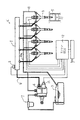
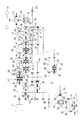
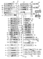
次に、図6の制御ブロック図で、制御信号の流れを説明する。
まず、エンジンECU(エンジン制御装置)12には、エンジン排気温度センサ106から排気の温度が入り、エンジン回転センサ107からエンジン回転数が入り、エンジンオイル圧力センサ108からエンジン潤滑オイルの圧力が入り、エンジン水温センサ109から冷却水の温度が入り、レール圧センサ2からコモンレール1の圧力が入り、燃料高圧ポンプ4に駆動信号が出力され、高圧インジェクタ6に燃料供給調整制御信号が出力される。
Next, the flow of the control signal will be described with reference to the control block diagram of FIG.
First, the engine ECU (engine control device) 12 receives the exhaust temperature from the engine
次に、作業機昇降制御装置110には、作業機昇降レバーに設けるポジションコントロールセンサ111の操作信号と、リフトアームセンサ112の昇降信号と、上げ位置規制ダイアル113の上げ位置規制信号と、下げ速度調整ダイアル114の降下速度設定信号がそれぞれ入力し、メイン上昇ソレノイド115とメイン下降ソレノイド116に作業機昇降信号が出力し作業機昇降シリンダを作動する。
Next, the work implement elevating
前記エンジンECU12と作業機昇降制御装置110、及び後述する走行制御装置120は制御信号が交互に交信(CAN1,CAN2通信)されて、エンジンEが標準出力カーブNであるか、又低燃費出力カーブSであるかの状態や、作業機の昇降状態、走行装置の走行速度等がメータパネル117に表示され、操作パネル118に各レバーやペダルの操作位置等が表示される。
The
走行制御装置120は、変速1クラッチ圧力センサ121、変速2クラッチ圧力センサ122、変速3クラッチ圧力センサ123、変速4クラッチ圧力センサ124からクラッチ入信号、即ち多段ギヤ変速装置の変速段が入力する。即ち、一速/三速切換用第一変速クラッチ34と、二速/四速切換用第二変速クラッチ35の信号である。Hi(高速)クラッチ圧力センサ125とLo(低速)クラッチ圧力センサ126からサブクラッチの変速位置が入力する。即ち、高・低速切換クラッチ50の信号である。
The
前進クラッチ圧力センサ127と後進クラッチ圧力センサ128からメインクラッチの前進・中立・後進が入力する。即ち、前後進切換クラッチ27の信号である。トラクタを前後進させる前後進レバーの位置を検出する前後進レバー操作位置センサ129と、副変速レバーの操作位置を検出する副変速レバー操作位置センサ130から変速操作位置信号が入力する。
From the forward clutch pressure sensor 127 and the reverse clutch pressure sensor 128, forward / neutral / reverse of the main clutch is input. That is, it is a signal of the forward /
車速センサ131から走行速度が入力し、ミッションオイル油温センサ132からミッションオイルの温度が入力し、クラッチペダル操作位置センサ133からクラッチペダルの踏込み信号が入力し、エンジンパワー選択スイッチ134から標準出力カーブNと低燃費出力カーブSの選択信号が入力し、エンジン回転数制御モード切換スイッチ148からエンジン制御モードの切換信号が入力する。手動スイッチ150からオン・オフ信号が入力する。
The travel speed is input from the
さらに、アクセル変更手段146であるアクセルペダルの踏込みによるアクセル開度Oがアクセルセンサ146aから入力する。アクセル開度OはエンジンEの出力を制御し、全開の80%程度を標準出力モード移行開度O2として、この標準出力モード移行開度O2を越えると、低燃費出力カーブSで走行していても標準出力カーブNに変更して出力を増大する。また、全開の60%程度を低燃費出力モード移行開度O1として、この低燃費出力モード移行開度O1が所定時間T(5秒)以上続くと、低燃費出力カーブSで走行して燃料の消費を少なくする。なお、アクセル変更手段146は、手動で操作するアクセルレバーであっても良い。
Furthermore, the accelerator opening degree O by the depression of the accelerator pedal which is the accelerator change means 146 is input from the accelerator sensor 146a. The accelerator opening degree O controls the output of the engine E. About 80% of the full opening is set as the standard output mode transition opening degree O2, and when the standard output mode transition opening degree O2 is exceeded, the vehicle travels on the low fuel consumption output curve S. Is also changed to the standard output curve N to increase the output. Further, about 60% of the full opening is set as the low fuel consumption output mode transition opening degree O1, and when the low fuel consumption output mode transition opening degree O1 continues for a predetermined time T (5 seconds) or longer, the vehicle travels on the low fuel consumption output curve S and runs out of fuel. Reduce consumption. The
アクセルペダルの踏み込み状態で走行(路上)の自動変速を行うアクセル変速設定スイッチ144からも信号が入力し、手動で変速の増減速を行う主変速増減速操作スイッチ145の操作信号が入力し、アクセルレバーの位置を検出してアクセル操作信号が入力し、アクセルを微調整するアクセル微調整レバーセンサ147のアクセル調整信号が入力する。 A signal is also input from an accelerator shift setting switch 144 that performs automatic shift (on the road) while the accelerator pedal is depressed, and an operation signal of a main shift acceleration / deceleration operation switch 145 that manually increases or decreases the shift is input. An accelerator operation signal is input by detecting the position of the lever, and an accelerator adjustment signal of an accelerator fine adjustment lever sensor 147 for finely adjusting the accelerator is input.
左ブレーキペダル102Lの踏込みが左ブレーキセンサ105から入力し、右ブレーキペダル102Rの踏込みが右ブレーキセンサ104から入力し、それぞれ左右のブレーキを作動させる。この左ブレーキペダル102Lと右ブレーキペダル102Rを使い分けるのは作業走行中であり、路上走行を行う場合には、左ブレーキペダル102Lと右ブレーキペダル102Rを一体に連結し、左右ブレーキ連結センサ103で連結を検出する。そして、この左右ブレーキ連結センサ103から連結信号が入力すると、エンジン回転数変動制御モードAで低燃費出力カーブSを用いたエンジン出力制御が行われ、走行負荷の変動に応じたエンジン回転の変動が行われ、左ブレーキセンサ105と右ブレーキセンサ104の踏込みによって走行速度が素早く低下する。
The depression of the
走行制御装置120からの出力は、前後進切換sol(ソレノイド)135に前後進切換クラッチの切換信号が出力し、リニア昇圧sol(ソレノイド)136に前後進切換sol(ソレノイド)を駆動する油圧のリリーフ圧調整信号が出力してクラッチ接続のショックを低減し、クラッチsol(ソレノイド)137に入・切信号が出力する。
As for the output from the traveling
さらに、一速/三速切換用第一変速クラッチ34を駆動する油圧シリンダの変速1−3切換sol(ソレノイド)138に一速又は三速の入信号が出力し、変速1−3昇圧sol(ソレノイド)139に一速/三速切換用第一変速クラッチ34を駆動する油圧のリリーフ圧調整信号が出力してクラッチ接続のショックを低減する。二速/四速切換用第二変速クラッチ35を駆動する油圧シリンダの変速2−4切換sol(ソレノイド)140に二速又は四速の入信号が出力し、変速2−4昇圧sol(ソレノイド)141に二速/四速切換用第二変速クラッチ35を駆動する油圧のリリーフ圧調整信号が出力してクラッチ接続のショックを低減する。高・低速切換クラッチ50を駆動する油圧シリンダを作動するHi(高速)クラッチ切換sol(ソレノイド)142とLo(低速)クラッチ切換sol(ソレノイド)143に高速クラッチの入信号及び低速クラッチの入信号が出力する構成である。
Further, a first-speed or third-speed input signal is output to a shift 1-3 switching sol (solenoid) 138 of the hydraulic cylinder that drives the first-speed / three-speed switching
その他の産業用車両にも適用可能である。 It can also be applied to other industrial vehicles.
A エンジン回転数変動制御モード
B エンジン回転数維持制御モード
C 重負荷モード
E エンジン
N 標準出力カーブ
O1 低燃費出力モード移行開度
O2 標準出力モード移行開度
S 低燃費エンジン出力カーブ
T 所定時間
102R 右ブレーキペダル
102L 左ブレーキペダル
103 連結センサ
146 アクセル変更手段
172b DPF
O アクセル開度
O1 低燃費出力モード移行開度
O2 標準出力モード移行開度
A Engine speed fluctuation control mode B Engine speed maintenance control mode C Heavy load mode E Engine N Standard output curve O1 Low fuel consumption output mode transition opening S2 Standard output mode transition opening S Low fuel consumption engine output curve T
O Accelerator opening O1 Low fuel consumption output mode transition opening O2 Standard output mode transition opening
Claims (4)
Priority Applications (1)
| Application Number | Priority Date | Filing Date | Title |
|---|---|---|---|
| JP2011016713A JP2012154302A (en) | 2011-01-28 | 2011-01-28 | Engine control of tractor |
Applications Claiming Priority (1)
| Application Number | Priority Date | Filing Date | Title |
|---|---|---|---|
| JP2011016713A JP2012154302A (en) | 2011-01-28 | 2011-01-28 | Engine control of tractor |
Publications (1)
| Publication Number | Publication Date |
|---|---|
| JP2012154302A true JP2012154302A (en) | 2012-08-16 |
Family
ID=46836274
Family Applications (1)
| Application Number | Title | Priority Date | Filing Date |
|---|---|---|---|
| JP2011016713A Pending JP2012154302A (en) | 2011-01-28 | 2011-01-28 | Engine control of tractor |
Country Status (1)
| Country | Link |
|---|---|
| JP (1) | JP2012154302A (en) |
Cited By (7)
| Publication number | Priority date | Publication date | Assignee | Title |
|---|---|---|---|---|
| WO2014116058A1 (en) * | 2013-01-24 | 2014-07-31 | 대동공업 주식회사 | Control system and control method for engine rpm of agricultural vechicle |
| WO2015068545A1 (en) * | 2013-11-08 | 2015-05-14 | 日立建機株式会社 | Wheel loader |
| WO2015141518A1 (en) * | 2014-03-20 | 2015-09-24 | ヤンマー株式会社 | Engine device |
| JP2015183552A (en) * | 2014-03-20 | 2015-10-22 | ヤンマー株式会社 | Engine device |
| JP2016180355A (en) * | 2015-03-24 | 2016-10-13 | ヤンマー株式会社 | Work vehicle |
| CN106133297A (en) * | 2014-03-27 | 2016-11-16 | 洋马株式会社 | Working truck |
| KR20200003257A (en) * | 2013-08-29 | 2020-01-08 | 얀마 가부시키가이샤 | Working vehicle |
-
2011
- 2011-01-28 JP JP2011016713A patent/JP2012154302A/en active Pending
Cited By (14)
| Publication number | Priority date | Publication date | Assignee | Title |
|---|---|---|---|---|
| WO2014116058A1 (en) * | 2013-01-24 | 2014-07-31 | 대동공업 주식회사 | Control system and control method for engine rpm of agricultural vechicle |
| KR102332863B1 (en) | 2013-08-29 | 2021-11-29 | 얀마 파워 테크놀로지 가부시키가이샤 | Working vehicle |
| KR20200003257A (en) * | 2013-08-29 | 2020-01-08 | 얀마 가부시키가이샤 | Working vehicle |
| US10392781B2 (en) | 2013-11-08 | 2019-08-27 | Kcm Corporation | Wheel loader |
| WO2015068545A1 (en) * | 2013-11-08 | 2015-05-14 | 日立建機株式会社 | Wheel loader |
| JP2015094070A (en) * | 2013-11-08 | 2015-05-18 | 日立建機株式会社 | Wheel loader |
| WO2015141518A1 (en) * | 2014-03-20 | 2015-09-24 | ヤンマー株式会社 | Engine device |
| JP2015183552A (en) * | 2014-03-20 | 2015-10-22 | ヤンマー株式会社 | Engine device |
| US10184375B2 (en) | 2014-03-20 | 2019-01-22 | Yanmar Co., Ltd. | Engine device |
| CN106133297A (en) * | 2014-03-27 | 2016-11-16 | 洋马株式会社 | Working truck |
| CN106133297B (en) * | 2014-03-27 | 2019-07-23 | 洋马株式会社 | work vehicle |
| KR102056516B1 (en) | 2014-03-27 | 2019-12-16 | 얀마 가부시키가이샤 | Industrial vehicle |
| EP3124774A4 (en) * | 2014-03-27 | 2017-12-27 | Yanmar Co., Ltd. | Industrial vehicle |
| JP2016180355A (en) * | 2015-03-24 | 2016-10-13 | ヤンマー株式会社 | Work vehicle |
Similar Documents
| Publication | Publication Date | Title |
|---|---|---|
| CN102128093A (en) | Engine control device for tractor | |
| JP2012154302A (en) | Engine control of tractor | |
| JP5730679B2 (en) | Engine equipment | |
| JP2013181406A (en) | Working vehicle | |
| JP2012246900A (en) | Tractor | |
| CN103118916B (en) | Drive system control device for work vehicle | |
| JP5176834B2 (en) | Work vehicle | |
| JP2014129733A (en) | Engine exhaust gas treatment device for work vehicle | |
| JP2014109213A (en) | Tractor | |
| JP2010156208A (en) | Diesel engine | |
| JP2014009639A (en) | Work vehicle | |
| JP2013024038A (en) | Work vehicle | |
| JP2012233430A (en) | Working vehicle | |
| JP2015045234A (en) | Tractor with exhaust gas treatment device | |
| JP2012229633A (en) | Tractor | |
| JP2011208591A (en) | Engine control apparatus | |
| JP5292926B2 (en) | Work vehicle | |
| JP2015143509A (en) | Tractor | |
| JP2011202633A (en) | Engine control device for tractor | |
| JP5315955B2 (en) | Tractor | |
| JP2014028584A (en) | Tractor | |
| JP2014088860A (en) | Work vehicle | |
| JP2012207636A (en) | Working vehicle | |
| JP2012052459A (en) | Working vehicle | |
| JP2014046754A (en) | Work vehicle |