JP2012155008A - Developing device, image forming device and developing method - Google Patents
Developing device, image forming device and developing method Download PDFInfo
- Publication number
- JP2012155008A JP2012155008A JP2011012001A JP2011012001A JP2012155008A JP 2012155008 A JP2012155008 A JP 2012155008A JP 2011012001 A JP2011012001 A JP 2011012001A JP 2011012001 A JP2011012001 A JP 2011012001A JP 2012155008 A JP2012155008 A JP 2012155008A
- Authority
- JP
- Japan
- Prior art keywords
- developer
- developing
- regulating member
- developing device
- developer regulating
- Prior art date
- Legal status (The legal status is an assumption and is not a legal conclusion. Google has not performed a legal analysis and makes no representation as to the accuracy of the status listed.)
- Pending
Links
Images





Landscapes
- Magnetic Brush Developing In Electrophotography (AREA)
- Dry Development In Electrophotography (AREA)
Abstract
【課題】2成分現像方式の現像装置において、現像領域直前での現像剤層の密度の均一性を高める。
【解決手段】現像スリーブ51Y内部に磁力発生手段を有し、磁力発生手段が発する磁気力により現像スリーブ51Y表面に現像剤を担持しながら、感光体の現像領域に現像剤を搬送して現像を行う現像装置において、現像スリーブ51Yに近接して配置される第1現像剤規制部材52Yと、第1現像剤規制部材52Yよりも現像剤搬送方向(R4方向)下流側であって、当該搬送方向下流側の現像極P2の直前に現像スリーブ51Yに近接して配置された第2現像剤規制部材56Yと、を備え、第2現像剤規制部材56Yと現像スリーブ51Yとの間隙が前記現像剤の搬送方向上流から下流にかけて狭くなるように(d2>d1)した。
【選択図】図4In a two-component developing type developing device, the density uniformity of a developer layer immediately before a developing region is improved.
A developing sleeve has a magnetic force generating means inside the developing sleeve, and the developer is transported to the developing area of the photosensitive member while developing on the surface of the developing sleeve by a magnetic force generated by the magnetic force generating means. In the developing device to be performed, the first developer regulating member 52Y disposed in the vicinity of the developing sleeve 51Y and the downstream side of the developer conveying direction (R4 direction) from the first developer regulating member 52Y, the conveying direction A second developer regulating member 56Y disposed in the vicinity of the developing sleeve 51Y immediately before the downstream developing electrode P2, and a gap between the second developer regulating member 56Y and the developing sleeve 51Y It was made narrower (d2> d1) from upstream to downstream in the transport direction.
[Selection] Figure 4
Description
本発明は潜像を電子写真方式で現像する現像装置、この現像装置を備えた画像形成装置及びこれらの各装置で実行される現像方法に関する。 The present invention relates to a developing device that develops a latent image by an electrophotographic method, an image forming apparatus including the developing device, and a developing method that is executed by each of these devices.
従来、電子写真方式の画像形成装置において、現像剤担持体上に現像剤を担持し、現像剤担持体上に担持された現像剤を、現像剤規制部材(ドクターブレード)で規制した後に感光体等の像担持体に対向する現像領域に搬送する現像装置が知られている。現像剤として磁性キャリアとトナーからなる2成分現像剤を用いた現像装置では、像担持体として内部に磁界発生手段を有する現像スリーブを用いる。現像スリーブは内部の磁界発生手段の磁力により現像スリーブ上に現像装置内に収容された現像剤を担持し、回転することで担持された現像剤を感光体と対向する現像領域に搬送する。現像スリーブに担持された現像剤は、途中、現像スリーブ表面とある距離(ドクターギャップ)を持って対向するように配置された現像剤規制部材との間隙を通過することによって一定量になるように規制される。 2. Description of the Related Art Conventionally, in an electrophotographic image forming apparatus, a developer is carried on a developer carrying member, and the developer carried on the developer carrying member is regulated by a developer regulating member (doctor blade), and then a photoreceptor. 2. Description of the Related Art A developing device that conveys a developing area facing an image carrier such as the like is known. In a developing device using a two-component developer composed of a magnetic carrier and toner as a developer, a developing sleeve having a magnetic field generating means inside is used as an image carrier. The developing sleeve carries the developer contained in the developing device on the developing sleeve by the magnetic force of the internal magnetic field generating means, and conveys the carried developer to the developing area facing the photoreceptor by rotating. The developer carried on the developing sleeve becomes a certain amount by passing through a gap with the developer regulating member arranged to face the developing sleeve surface with a certain distance (doctor gap) on the way. Be regulated.
ドクターギャップを通過した現像剤の単位面積当りの量は汲み上げ量と呼ばれる。この汲み上げ量が現像スリーブと感光体とが対向する現像領域の間隙に対して多すぎると、現像剤が現像領域内で押し合い、そのときのせん断応力により摩擦発熱し、現像剤自体が溶解して固着するという不具合が生じる。 The amount of developer per unit area that has passed through the doctor gap is called the pumping amount. If the pumping amount is too large relative to the gap between the developing areas where the developing sleeve and the photoconductor face each other, the developer presses in the developing area, and frictional heat is generated due to shear stress at that time, and the developer itself dissolves. The problem of sticking occurs.
一方、汲み上げ量が少ないと、感光体に十分なトナーを供給することができずに、画像濃度低下という不具合が生じる。このため、安定して高品位の画像を得るためには、適正な汲み上げ量を確保して、感光体との対向部に搬送することが必要になっている。また、現像剤規制部材としては、金属の板部材、丸棒部材が広く用いられている。 On the other hand, when the pumping amount is small, sufficient toner cannot be supplied to the photosensitive member, resulting in a problem that the image density is lowered. For this reason, in order to stably obtain a high-quality image, it is necessary to secure an appropriate pumping amount and to convey it to a portion facing the photoconductor. Further, as the developer regulating member, a metal plate member or a round bar member is widely used.
このような不具合を解決する技術として、例えば特許文献1(特開2009−092834号公報)に記載された発明が公知である。この発明では、印刷開始直後と連続印刷時のトナー帯電量の差をなくし、トナーの帯電量を安定させるため、表面に現像剤を担持して潜像担持体まで現像剤を搬送して潜像担持体に画像を形成する現像剤担持体と、前記担持体への画像形成個所より現像剤担持体上流側に配置され前記現像持体上の現像剤の量を規制する現像剤規制部材と、を有する現像装置において、現像剤規制部材の上流側に、現像剤担持体との間隔寸法を変更できる前置規制部材を配置したことを特徴とするものである。 As a technique for solving such a problem, for example, an invention described in Patent Document 1 (Japanese Unexamined Patent Application Publication No. 2009-09834) is known. In the present invention, in order to eliminate the difference in the toner charge amount immediately after the start of printing and during continuous printing and to stabilize the toner charge amount, the developer is carried on the surface and conveyed to the latent image carrier and the latent image is transferred. A developer carrying member that forms an image on the carrying member, a developer regulating member that is disposed on the upstream side of the developer carrying member from an image forming position on the carrying member and regulates the amount of the developer on the developing carrier; In the developing device having the above, a front regulating member capable of changing a distance between the developer carrying member and an upstream side of the developer regulating member is arranged.
しかし、前記特許文献1記載の発明では、印刷開始直後と連続印刷時のトナー帯電量の差をなくし、トナーの帯電量を安定させることはできるが、汲み上げ量を適正な量に規制し、現像剤層の不均一性を解消することはできない。
However, in the invention described in
すなわち、特許文献1記載の発明も含め、これまでの現像装置では、現像剤規制部材通過後の現像剤層は、現像領域に搬送されるまでの間に磁極により磁気穂が寝起きすることでバラツキが生じる。そのため現像領域での現像剤層の密度は、現像剤規制部材通過後と比較して不均一となる。現像領域中での現像剤の密度が不均一であると、磁気穂の長さが不均一となり、画像の粒状性が悪化する要因となっていた。
In other words, in the conventional developing apparatus including the invention described in
そこで、本発明が解決しようとする課題は、2成分現像方式の現像装置において、現像領域直前での現像剤層の密度の均一性を高めることにある。 Therefore, the problem to be solved by the present invention is to improve the uniformity of the density of the developer layer immediately before the development area in the two-component development type development apparatus.
前記課題を解決するため、第1の手段は、現像剤担持体内部に磁力発生手段を有し、前記磁力発生手段が発する磁気力により現像剤担持体表面に現像剤を担持しながら、像担持体の現像領域に前記現像剤を搬送して現像を行う現像装置であって、前記現像剤担持体に近接して配置される第1の現像剤規制部材と、前記第1の現像剤規制部材よりも現像剤搬送方向下流側であって、現像剤領域の搬送方向下流側の現像極の直前に前記現像剤担持体に近接して配置された第2の現像剤規制部材と、を備え、前記第2の現像剤規制部材と前記現像剤担持体との間隙が前記現像剤の搬送方向上流から下流にかけて狭くなるように設定されていることを特徴とする。 In order to solve the above-mentioned problem, the first means has a magnetic force generating means inside the developer carrying member, and carries the image on the surface of the developer carrying member by the magnetic force generated by the magnetic force generating means. A developing device for carrying out development by transporting the developer to a developing region of a body, wherein the first developer regulating member is disposed in proximity to the developer carrying member, and the first developer regulating member A second developer regulating member disposed in the vicinity of the developer carrying body immediately before the development pole downstream of the developer transport direction and downstream of the developer region in the transport direction, The gap between the second developer regulating member and the developer carrier is set so as to become narrower from the upstream to the downstream in the transport direction of the developer.
この場合、前記第1の現像剤規制部材と現像剤担持体との間の間隙をd0、前記第2の現像剤規制部材と前記現像剤担持体の前記下流側の狭くなった部分の間隙をd1としたとき、両者の比d1/d0が0.7〜1の範囲に設定する。 In this case, the gap between the first developer regulating member and the developer carrying member is d0, and the gap between the second developer regulating member and the narrowed portion on the downstream side of the developer carrying member is made. When d1, the ratio d1 / d0 of both is set in the range of 0.7-1.
また、前記第2の現像剤規制部材は平板部材あるいは円柱部材によって構成する。円柱部材を第2の現像剤規制部材として用いる場合には、前記円柱部材の表面を摩擦係数0.2以下の材料でコートすることが望ましい。更に、前記現像剤担持体の表面と、それに対向する前記第2の現像剤規制部材としての円柱部材の表面が同一方向に移動するように両者の回転方向を設定する。 Further, the second developer regulating member is constituted by a flat plate member or a cylindrical member. When a cylindrical member is used as the second developer regulating member, it is desirable to coat the surface of the cylindrical member with a material having a friction coefficient of 0.2 or less. Furthermore, the rotation direction of both is set so that the surface of the developer carrying member and the surface of the cylindrical member as the second developer regulating member facing the developer carrier move in the same direction.
第2の手段は、第1の手段に係る現像装置を画像形成装置が備えていること特徴とする。 The second means is characterized in that the image forming apparatus includes the developing device according to the first means.
第3の手段は、現像剤担持体内部の磁力発生手段を有し、前記磁力発生手段が発する磁気力により現像剤担持体表面に現像剤を担持しながら、像担持体の現像領域に前記現像剤を搬送して現像を行う現像方法であって、前記現像剤担持体に近接して配置される第1の現像剤規制部材で現像剤の汲み上げ量を一定量に規制する工程と、前記第1現像剤規制部材よりも現像剤搬送方向下流側かつ現像極の直前に前記現像剤担持体に近接して配置された第2の現像剤規制部材によって、前記工程で汲み上げ量が一定に規制された現像剤層の密度を整えて前記現像領域まで現像剤を搬送する工程と、を備えていることを特徴とする。 The third means includes a magnetic force generating means inside the developer carrying member, and the developer is carried on the surface of the developer carrying member by the magnetic force generated by the magnetic force generating means, and the developing is performed on the developing area of the image carrier. A developing method for carrying out development by transporting the developer, the step of regulating the pumping amount of the developer to a fixed amount by a first developer regulating member disposed in the vicinity of the developer carrying member; The pumping amount is regulated at a constant level in the step by the second developer regulating member disposed in the vicinity of the developer carrying member downstream of the developer regulating member in the developer transport direction and immediately before the developing pole. And a step of adjusting the density of the developer layer and transporting the developer to the development area.
なお、後述の実施形態では、現像剤担持体は現像スリーブ51Yに、現像剤は符号Tに、現像装置は符号5Yに、第1の現像剤規制部材は第1現像剤規制部材(ドクター)52Yに、現像極は符号P2に、第2の現像剤規制部材は第2現像剤規制部材56Yに、間隙は符号d1及びd2に、平板部材からなる第2の現像剤規制部材は第2現像剤規制部材56Yに、円柱部材からなる第2の現像剤規制部材は第2現像剤規制部材561Yに、画像形成装置はプリンタ100にそれぞれ対応する。
In the embodiment described later, the developer carrying member is the developing
本発明によれば、2成分現像方式の現像装置において、現像領域直前での現像剤層の密度の均一性を高めることができる。 According to the present invention, in the two-component developing type developing apparatus, it is possible to improve the uniformity of the density of the developer layer immediately before the developing region.
本発明は、2成分現像装置における現像剤規制部材において、第1の現像剤規制部材で汲み上げ量を一定量に規制した後に、第2の現像剤規制部材で現像剤層の密度を整えることを特徴とする。 According to the present invention, in the developer regulating member in the two-component developing device, after the pumping amount is regulated to a certain amount by the first developer regulating member, the density of the developer layer is adjusted by the second developer regulating member. Features.
以下、本発明の実施形態について図面を参照しながら詳細に説明する。 Hereinafter, embodiments of the present invention will be described in detail with reference to the drawings.
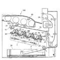
図1は、本実施形態の実施例1に係る画像形成装置の概略構成を示す図である。なお、本実施例1における画像形成装置は、電子写真方式のプリンタ(以下、単にプリンタと称する。)であり、外部から入力される画像データに基づいてシート状記録媒体に画像を形成する。なお、本プリンタでは、作像部にはプロセスカートリッジが使用されている。 FIG. 1 is a diagram illustrating a schematic configuration of an image forming apparatus according to Example 1 of the present embodiment. The image forming apparatus according to the first exemplary embodiment is an electrophotographic printer (hereinafter simply referred to as a printer), and forms an image on a sheet-like recording medium based on image data input from the outside. In this printer, a process cartridge is used for the image forming unit.
図1において、このプリンタ100は、イエロー、マゼンタ、シアン、ブラック(以下、Y、M、C、Kと記す。)のトナー像を生成するための4つのプロセスカートリッジ6Y、6M、6C、6Kを備えた作像部と、作像部へ光書き込みを行う光書き込み部と、作像部で作像された画像を1次転写する中間転写部と、中間転写部で転写された画像をシート状記録媒体に2次転写する2次転写部と、2次転写部にシート状記録媒体を供給する給紙部と、2次転写された画像をシート状記録媒体上に定着させる定着部と、画像が定着されたシート状記録媒体をスタック部30に排紙する排紙部と、から基本的に構成されている。
In FIG. 1, the
作像部における4つのプロセスカートリッジ6Y、6M、6C、6Kは、画像形成物質として、互いに異なる色のY、M、C、Kトナーを用いるが、それ以外は同様の構成になっており、寿命到達時に交換される。
The four
図2は図1の現像装置を拡大して示す図である。Yトナー像を生成するためのプロセスカートリッジ6Yを例にすると、図2に示すようにドラム状の感光体1Y、ドラムクリーニング装置2Y、除電装置(不図示)、帯電装置4Y、現像装置5Y等を備えている。このプロセスカートリッジ6Yは、プリンタ100本体に脱着可能であり、消耗部品を一体的に交換できるようになっている。
FIG. 2 is an enlarged view of the developing device of FIG. Taking a
上記帯電装置4Yは、図示しない駆動手段によって図中時計回りに回転駆動される感光体1Yの表面を一様に帯電する。一様に帯電した感光体1Yの表面は、レーザ光Lによって露光走査されてY用の静電潜像を担持する。このYの静電潜像は、Yトナーを用いる現像装置5YによってYトナー像に現像される。そして、中間転写部としての中間転写ベルト8上に中間転写される。ドラムクリーニング装置2Yは、中間転写工程を経た後の感光体1Y表面に残留したトナーを除去する。また、除電装置は、クリーニング後の感光体1Yの残留電荷を除電する。この除電により、感光体1Yの表面が初期化されて次の画像形成に備えられる。他のプロセスカートリッジ6M、6C、6Kにおいても、同様にして感光体1M、1C、1K上にM、C、Kトナー像が形成され、中間転写ベルト8上に中間転写される。
The charging
先に示した図1においてプロセスカートリッジ6Y、M、C、Kの図中下方には光書き込み部としての露光装置7が配設されている。
In FIG. 1 shown above, an
露光装置7は、画像情報に基づいて発したレーザ光Lを、各プロセスカートリッジ6Y、6M、6C、6Kにおけるそれぞれの感光体に照射して露光する。この露光により、感光体1Y、1M、1C、1K上にY、M、C、K用の静電潜像が形成される。なお露光装置7は、光源から発したレーザ光Lを、モータによって回転駆動したポリゴンミラーで走査しながら、複数の光学レンズやミラーを介して感光体に照射するものである。
The
露光装置7の図中下側には、紙収容カセット26、これらに組み込まれた給紙ローラ27、レジストローラ対28など有する給紙部が配設されている。紙収容カセット26は、シート状記録媒体としての転写紙Pが複数枚重ねて収納されており、それぞれの一番上の転写紙Pには給紙ローラが当接している。給紙ローラ27が図示しない駆動手段によって図中反時計回りに回転駆動されると、最上位の転写紙Pがレジストローラ対28のニップに向けて給紙される。レジストローラ対28は、停止した状態で両ローラのニップに転写紙Pを当接させ、転写紙Pの先端縁を揃え、その後、転写紙Pを挟み込むため両ローラを回転駆動するが、挟み込んですぐに回転を一旦停止させる。そして、転写紙Pを中間転写ベルト8上の1次転写画像の先端部とタイミングを合わせ、後述の2次転写部に向けて送り出す。このように構成された給紙部では、給紙ローラ27と、タイミングローラ対として機能するレジストローラ対28との組み合わせによって搬送手段が構成されている。この搬送手段は、転写紙Pを紙収容カセット26から2次転写部の2次転写ニップまで搬送する。
On the lower side of the
プロセスカートリッジ6Y、6M、6C、6Kの図中上方には、後述のローラ間に張設された無端状の中間転写ベルト8を回転移動させる中間転写ユニット15が配設されている。この中間転写ユニット15は、中間転写ベルト8の他、4つの1次転写バイアスローラ9Y、9M、9C、9K、クリーニング装置10などを備えている。また2次転写バックアップローラ12、クリーニングバックアップローラ13、テンションローラ14なども備えている。中間転写ベルト8は、これら3つのローラ12,13,14間に張設された状態で少なくとも何れか1つのローラの回転駆動によって図中矢印R3方向(反時計回り)に回転する。
Above the
1次転写バイアスローラ9Y、9M、9C、9Kは、このような中間転写ベルト8を感光体1Y、1M、1C、1Kとの間に挟み込んでそれぞれ1次転写ニップを形成している。これらは中間転写ベルト8の裏面(ループ内周面)にトナーとは逆極性(例えばプラス)の転写バイアスを印加する方式のものである。1次転写バイアスローラ9Y、9M、9C、9Kを除くローラは、全て電気的に接地されている。中間転写ベルト8では、その無端移動に伴ってY、M、C、K用の1次転写ニップを順次通過していく過程で、感光体1Y、1M、1C、1K上のY、M、C、Kトナー像が重ね合わされて中間転写ベルト8上に1次転写される。これにより、中間転写ベルト8上に4色重畳されたトナー像(以下、4色トナー像と称す。)が形成される。
The primary
上記2次転写バックアップローラ12は、2次転写ローラ19との間に中間転写ベルト8を挟み込んで2次転写ニップを形成している。中間転写ベルト8上に形成された4色トナー像は、この2次転写ニップで転写紙Pに転写される。2次転写ニップを通過した後の中間転写ベルト8には、転写紙Pに転写されなかった転写残トナーが付着している。これは、クリーニングバックアップローラ13の下流側直後に配置されたクリーニング装置10によってクリーニングされる。
The secondary
上記2次転写ニップにおいては、転写紙Pが互いに順方向に表面移動する中間転写ベルト8と2次転写ローラ19との間に挟まれて、上記レジストローラ対28側に対して下流側に搬送される。2次転写ニップから送り出された転写紙Pは、定着部としての定着装置20のローラ間を通過する際に熱と圧力により、表面に転写された4色トナー像が定着される。その後、転写紙Pは、排紙ローラ対29のローラ間を経て機外へと排出される。
In the secondary transfer nip, the transfer paper P is sandwiched between the
プリンタ本体の上面には、スタック部30が形成されており、上記排紙ローラ対29によって機外に排出された転写紙Pは、このスタック部30に順次スタックされる。したが、本実施例では、排紙ローラ29とスタック部30によって排紙部が構成される。
A
上記プロセスカートリッジ6Y内の現像装置5Yは、図2に示すように内部に磁界発生手段を備え、磁性粒子とトナーを含む2成分系現像剤を表面担持して搬送する現像剤担持体としての現像スリーブ51Yと、現像スリーブ51Y上に担持されて搬送される現像剤の層厚を規制する現像剤規制部材としてのドクター(第1現像剤規制部材)52Yとを備えている。ドクター52Yの現像剤搬送方向上流側には、感光体1Yと対向した現像領域に搬送されずにドクター52Yで規制された現像剤を収容する1軸側現像剤収容部53Yが形成されている。また、1軸側現像剤収容部53Yに隣接し、トナーが補給される2軸側現像剤収容部54Yが形成されている。1軸側現像剤収容部53Yと2軸側現像剤収容部54Yには、それぞれ、現像剤を攪拌搬送するための2本の現像剤搬送スクリュ55Yが設けられている。
As shown in FIG. 2, the developing
このように構成された現像装置5Yでは、現像スリーブ51Y上に現像剤層が形成される。また、トナーは、現像剤搬送スクリュ55Yの2軸側に、中間転写ユニット15の上部には位置されたトナーボトル32Yから補給され、攪拌搬送されて現像剤内に取り込まれる。具体的には、トナーボトル53Y内のトナー濃度を検出するトナー濃度センサからのセンサ出力が制御部57Yに入力され、制御部57Yで現像剤中のトナー濃度を検出する。制御部57Yでは、検出したトナー濃度に基づいてトナーの取り込みの是非を判断し、トナーを取り込む場合には、駆動モータ41Yによって現像剤搬送スクリュ55Yを駆動し、トナーボトル32Yからトナーを取り込む。なお、このトナー取り込みの判断は、現像剤のトナー濃度が所定の範囲内か否かに基づいて行われる。
In the developing
現像剤中に取り込まれたトナーは、キャリアとの摩擦帯電により帯電する。帯電したトナーを含む現像剤は、内部に磁極を有する現像スリーブ51Yの表面に供給され、磁力により担持される。現像スリーブ51Yに担持された現像剤層は、現像スリーブ51Yの回転に伴い矢印R1方向に搬送される。途中、現像剤層は第1現像剤規制部材52Yで層厚を規制された後、第2現像剤規制部材56Yで均一にされ、感光体1Yと対向する現像領域まで搬送される。現像領域では、感光体1Yが矢印R2方向に回転しながら感光体1Y上に形成された潜像に基づく現像が行われる。現像スリーブ51Y上に残った現像剤層は現像スリーブ51Yの回転に伴い1軸側現像剤収容部53Yの現像剤搬送方向上流部分に搬送される。
The toner taken into the developer is charged by frictional charging with the carrier. The developer containing charged toner is supplied to the surface of the developing
なお、イエロートナーボトル32Yのみならず、マゼンタトナーボトル32M、シアントナーボトル32C及びブラックトナーボトル32は中間転写ユニット15とスタック部30との間に形成されたトナーボトル収容部31に収容され、各色のトナーを各色のプロセスユニットの2軸側現像剤収容部に供給する。
Not only the
図3は現像スリーブと現像剤規制部材の関係を示す図で、図2の要部を拡大して示している。同図において現像スリーブ51Yの下側に第1現像剤規制部材(ドクター)52Yと第2現像剤規制部材56Yが配置されている。第2現像剤規制部材56Yは図3に示すように、第1現像剤規制部材52Yの回転方向(図示矢印R1方向)下流側に位置している。
FIG. 3 is a diagram showing a relationship between the developing sleeve and the developer regulating member, and shows an enlarged main part of FIG. In the drawing, a first developer regulating member (doctor) 52Y and a second
図4は現像スリーブ51Yの内部の磁力発生手段による現像スリーブ51Y上の法線方向磁束密度分布を示す図である。P1は現像剤収容部53Yから現像剤を現像スリーブ51Yに汲み上げるための汲み上げ極であり、P2は現像領域で感光体1Y上に形成された潜像に現像を行うための現像極である。第1現像剤規制部材52Yは汲み上げ極P1上に配置され、第2現像剤規制部材56Yは汲み上げ極P1と現像極P2との間に配置されている。このように第2現像剤規制部材56Yを第1現像剤規制部材52Yよりも現像剤搬送方向(図示矢印R4方向)下流であって、かつ現像極P2の直前に配置することにより、現像極P1で穂立ちする直前に第2現像剤規制部材56Yで現像剤層の密度を均一にすることができる。これにより現像領域で均一な磁気穂を形成することが可能となる。
FIG. 4 is a diagram showing a normal direction magnetic flux density distribution on the developing
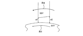
図5は図4における第2現像剤規制部材56Yの先端部を拡大して示す図である。本実施例では、第2現像剤規制部材56YとしてSUSで形成された板部材を用いた。第2現像剤規制部材56Yは先端部を現像スリーブ51Yに対向させた状態で固定されている。第2現像剤規制部材56Yと現像スリーブ51Yとの間隙は現像剤搬送方向(図示矢印R4方向)上流から下流に向けて、狭まるように配設されている。第2現像剤規制部材56Yの現像剤出口側の間隙をd1、現像剤入口側の間隙をd2とすると
d1<d2
となっている。
FIG. 5 is an enlarged view showing the tip of the second
It has become.
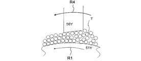
図6は第2現像剤規制部材56Yと現像スリーブ51Y間の現像剤の状態を示す模式図である。第2現像剤規制部材56Yの先端部と現像スリーブ51Y間の間隙が現像剤搬送方向(矢印R4)で図6に示すように徐々に狭まると、現像剤Tが適度に圧縮され、第2現像剤規制部材56Y通過後の現像剤の密度を均一にすることができる。このとき、現像剤Tは第1現像剤規制部材52Yで汲み上げ量が規制されており、また、図3に示すように第1現像剤規制部材52Yと現像スリーブ51Yとの間隙をd0とすると、
d0=d2>d1
という関係に間隙d0が設定されているために、第2現像剤規制部材56Yで圧縮される際に過度のストレスが掛かることがなく、現像剤Tの密度を均一にすることができる。
FIG. 6 is a schematic diagram showing the state of the developer between the second
d0 = d2> d1
Since the gap d0 is set in such a relationship, excessive stress is not applied when compressed by the second
本実施例における第2現像剤規制部材56Yを使用したときの粒状性ランクを図9及び図10に示す。この粒状性ランクは図7及び図8の実験条件(1),(2)で実験したときの結果を示すものである。実験条件は、前記間隙d0(=距離)を一定、間隙d1(=距離)を変数として両者間の比d1/d0をパラメータとしている。粒状性ランクは、出力画像の粒状性を示す指標であり、数値が大きくなるほど、粒状性が良好になっていることを表している。図9及び図10から比d1/d0を1以下にすると、現像領域中での現像剤層の密度が均一になり、出力画像の粒状性が向上することが分かる。ただし、比d1/d0を小さくしすぎると、第2現像剤規制部材56Y部分で現像剤が通過できずに溢れてしまう不具合が生じたため、比d1/d0は0.7より大きくする必要がある。最適には0.7〜1の範囲である。
The granularity rank when the second
なお、本実施例では、プロセスカートリッジ6Y内の現像装置5Yについて説明しているが、他のM、C、K各色のプロセスカートリッジ6M、6C、6K内の現像装置5M、5C、5Kにおいても同様であることはいうまでもない。
In the present embodiment, the developing
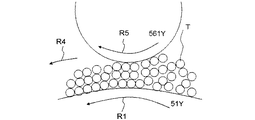
図11は実施例2における現像スリーブ51Yと第2現像剤規制部材561Y間の現像剤の状態を示す模式図であり、実施例1における図6に対応する。なお、実施例2は第2現像剤規制部材561Yを除いて実施例1と同一であるので、同一の各部には同一の参照符号を付し、重複する説明は省略する。
FIG. 11 is a schematic diagram illustrating a state of the developer between the developing
実施例2における第2現像剤規制部材561Yは図11に示すように円柱棒から構成されている。現像剤規制部材として広く用いられている板状部材は一般的にプレス切断により形成された後に、切削や研磨処理等の2次処理を施して長手方向に均一平面として使用する。このようにして作成すると、工程が多いことからコスト高となっている。一方で丸棒を用いる場合、押出成型で形成することができるために板状部材と比較して低コストとすることができる。
The second
そこで、丸棒を第2現像剤規制部材561Yとして用いると、丸棒が曲率を持って現像スリーブ51Yに対向することになる。このような相対関係にあると、実施例1と同様に、現像スリーブ51Yとの第2現像剤規制部材561Y間の間隙が現像剤搬送方向(矢印R4方向)上流から下流に向けて狭まる構成となる。そのため、現像剤層の密度が均一となり、粒状性の良好な画像を得ることができる。その際、第2現像剤規制部材561Y部に搬送される現像剤は実施例1と同様に第1現像剤規制部材52Yの前記間隔d0で一定量に規制されているため、第2現像剤規制部材561Yで過度にストレスが掛かることなく現像剤層の密度を均一にすることができる。なお、本実施例では直径10mmのアルミで形成された円柱棒を用いた。
Therefore, when a round bar is used as the second
また、円柱棒からなる第2現像剤規制部材561Yは回転可能に支持されており、不図示の駆動源からから動力を受け、現像スリーブ51Y表面と第2現像剤規制部材561Y表面が同一方向に移動する方向に回転させることができる(矢印R1方向及び矢印R5方向)。このように第2現像剤規制部材561Yを回転させると、第2現像剤規制部材561Yと現像剤との摩擦による現像剤へのストレスが低減し、現像剤の寿命を延ばすことができる。
Further, the second
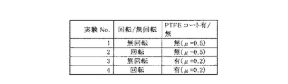
また、第2現像剤規制部材561Yの表面にPTFE(ポリテトラフルオロエチレン)のコート層を形成することもできる。PTFEは摩擦係数が非常に小さい物質であるため、PTFEのコート層を形成すると、前記第2現像剤規制部材561Yと現像剤Tの摩擦による現像剤Tへのストレスを更に低減させることが可能となり、現像剤Tの寿命を更に延ばすことができる。なお、本実施例2では、コート材料としてPTFEを使用しているが、PTFEに限らず他の低摩擦係数の材料を使用することができることはいうまでもない。
Also, a PTFE (polytetrafluoroethylene) coat layer can be formed on the surface of the second
本実施例における第2現像剤規制部材561Yを使用したときの現像剤寿命を図13に示す。この現像剤寿命は図12の実験条件(3)で実験したときの結果を示すものである。本実験では、前記直径10mmのアルミで形成された円柱棒を第2現像剤規制部材561Yとして使用し、円柱棒の回転/無回転、及びPTFEのコートの有/無の組み合わせに対して現像剤寿命を計測したものである。ここで現像剤Tの寿命とは、現像剤Tに削れが発生し、現像剤Tが微粉化するなどの劣化が生じ、これによる帯電特性の低下によって地肌汚れに至るまでの出力枚数で決定している。
FIG. 13 shows the developer life when the second
図12に示す摩擦係数μの測定は、原子間力顕微鏡を用いて行った。以下に、原子間力顕微鏡とそれを用いた付着力測定方法の概要を述べる。
原子間力顕微鏡(AFM)の動作原理については多くの公知の文献(例えばAppl.Phys. Lett.56号1758頁(1990年))がある。窒化ケイ素や2酸化ケイ素などの物質表面を有する針(プローブチップ、以下、チップともいう。)を先端に有するカンチレバーを用いて、チップを測定試料表面に近付けて、試料表面間とプローブチップの間に働く力(表面間力)、もしくはサンプル・カンチレバー間の摩擦力を、フォトダイオードの反射を用いてカンチレバーの反りあるいは撓みとして測定し、シグナルとしてフィードバック制御に結び付け、チップと試料表面との間の距離をピエゾ素子によって制御するというのが代表的なAFMの動作原理である。
原子間力顕微鏡を用いて付着力、もしくは摩擦力を測定する際は、カンチレバーを装飾しなければならない。具体的には、エポキシ樹脂等の接着剤で、カンチレバー先端に対象の粉体を取り付ける。取り付ける作業は、特開2002−62253号公報に記載されているような専用機器を用いるか、もしくはAFMによっても、取り付けることができる。
The measurement of the friction coefficient μ shown in FIG. 12 was performed using an atomic force microscope. The outline of an atomic force microscope and an adhesion force measuring method using the same will be described below.
There are many known documents (for example, Appl. Phys. Lett. 56, 1758 (1990)) regarding the principle of operation of an atomic force microscope (AFM). Using a cantilever having a needle having a material surface such as silicon nitride or silicon dioxide (probe tip, hereinafter also referred to as a tip) at the tip, the tip is brought close to the measurement sample surface, and between the sample surface and the probe tip The force acting on the surface (surface force) or the friction force between the sample and the cantilever is measured as the cantilever warpage or deflection using the reflection of the photodiode, and is linked to feedback control as a signal between the tip and the sample surface. Controlling the distance with a piezo element is a typical AFM operating principle.
When measuring adhesion or frictional force using an atomic force microscope, the cantilever must be decorated. Specifically, the target powder is attached to the cantilever tip with an adhesive such as an epoxy resin. The attaching operation can be performed by using a dedicated device as described in JP-A-2002-62253 or by AFM.
摩擦力は、SIIナノテクノロジー株式会社 Application Brief SPI no.37 「フリクショナルカーブによる定量的摩擦特性評価I」に基づいて算出することが可能である。 The frictional force can be calculated based on SII Nano Technology Co., Ltd. Application Brief SPI no.37 “Quantitative Friction Characteristic Evaluation I by Friction Curve I”.
以下に、本実施例における測定条件を示す。
・計測条件(フリクショナルカーブ法):原子間力顕微鏡(AFM):走査型プローブ顕微鏡SPI4000、多機能型ユニットSPA400(SIIナノテクノロジー(株)製)
・測定モード:AFMモード
・カンチレバー:SIIナノテクノロジー(株)社製 シリコンカンチレバーSI−DF20、バネ定数:20[N/m]
・スキャン条件:10000[nm]を、0.2Hzで往復スキャン
・負荷条件:カンチレバー先端と試料表面の押し付け負荷0、1500、5000[nN]狙いで設定
・カンチレバー先端のキャリア粒径:35[μm]
・キャリア種類:(株)リコー社製キャリア
・摩擦力算出方法:SIIナノテクノロジー株式会社 Application Brief SPI no.37 「フリクショナルカーブによる定量的摩擦特性評価I」の内容にしたがって算出
・摩擦係数算出方法:押し付け負荷に対する、摩擦力の1次変化で算出
Below, the measurement conditions in a present Example are shown.
Measurement conditions (frictional curve method): atomic force microscope (AFM): scanning probe microscope SPI4000, multifunctional unit SPA400 (manufactured by SII Nanotechnology Co., Ltd.)
・ Measurement mode: AFM mode
Cantilever: Silicon cantilever SI-DF20 manufactured by SII Nano Technology Co., Ltd., spring constant: 20 [N / m]
・ Scanning conditions: 10000 [nm], reciprocating scan at 0.2 Hz
・ Loading condition: Set with the aim of 0, 1500, 5000 [nN] pressing load between the cantilever tip and sample surface
・ Carrier particle size at the tip of the cantilever: 35 [μm]
・ Career type: Carrier made by Ricoh Co., Ltd.
・ Friction force calculation method: SII Nano Technology Co., Ltd. Application Brief SPI no.37 Calculated according to the contents of “Quantitative friction characteristic evaluation I by frictional curve” ・ Friction coefficient calculation method: Primary change of friction force against pressing load Calculated with
この測定法による本実施例の第2現像剤規制部材の摩擦係数を測定したところ、PTFEをコートした場合μ=0.2となり、PTFEをコートしていない場合μ=0.5となった。 When the coefficient of friction of the second developer regulating member of this example was measured by this measurement method, μ = 0.2 when PTFE was coated, and μ = 0.5 when PTFE was not coated.
図12の実験条件(3)で実験した結果を図13に示す。図13から、第2現像剤規制部材561Yを回転させると回転させない場合に比べて現像剤寿命が向上し、第2現像剤規制部材561YにPTFEにコートを施すことによりコートを施さない場合に比べて現像剤寿命が向上することが分かる。
FIG. 13 shows the result of the experiment performed under the experimental condition (3) in FIG. From FIG. 13, when the second
このように寿命を向上させることができるのは、第2現像剤規制部材561Yを回転させた場合も、当該部材にコートを施した場合も、いずれの場合も現像剤が間隙(d2→d1)を通過する際に、現像剤に掛かるストレスを低減することができたからであると考えられる。
The lifetime can be improved in this way, whether the second
なお、実施例2においても、プロセスカートリッジ6Y内の現像装置5Yについて説明しているが、他のM、C、K各色のプロセスカートリッジ6M、6C、6K内の現像装置5M、5C、5Kにおいても同様である。
In the second embodiment, the developing
以上のように、本実施形態によれば、第1現像剤規制部材52Yで現像剤Tの汲み上げ量を一定量に規制した後に、第2現像剤規制部材56Y,561Yによって現像剤層の密度を整えて、その後、現像極P2によって形成される現像領域まで現像剤Tを搬送する。第2現像剤規制部材56Y,561Yは、現像剤搬送方向上流から下流に向かうにつれて現像スリーブ51Yとの間隙(ドクターギャップ)が狭くなる形状(間隙がd2からd1に減少)をしているため、現像剤Tに適度に圧力がかかり、現像剤層の密度及び現像剤層表面高さが均一となる。その結果、第2現像剤規制部材56Y,561Y通過後の現像剤層の均一性を高めることができる。
As described above, according to the present embodiment, the developer developer density is adjusted by the second
なお、本発明は前述した実施形態に限定されず、本発明の要旨を逸脱しない範囲で種々の変形が可能であり、特許請求の範囲に記載された技術思想に含まれる技術的事項の全てが本発明の対象となる。前記各実施例は、好適な実施形態をそれぞれ示したものであるが、当業者ならば、本明細書に開示の内容から、各種の代替例、修正例、変形例あるいは改良例を実現することができ、これらは添付の特許請求の範囲により規定される範囲に含まれる。 The present invention is not limited to the above-described embodiments, and various modifications can be made without departing from the gist of the present invention, and all technical matters included in the technical idea described in the claims are included. The subject of the present invention. Each of the above examples shows a preferred embodiment, but those skilled in the art will realize various alternatives, modifications, variations, and improvements from the contents disclosed in this specification. Which fall within the scope defined by the appended claims.
5Y 現像装置
51Y 現像スリーブ
52Y 第1現像剤規制部材(ドクター)
56Y,561Y 第2現像剤規制部材
100 プリンタ
d0,d1,d2 間隙
P2 現像極
T 現像剤
56Y, 561Y Second
Claims (8)
前記現像剤担持体に近接して配置される第1の現像剤規制部材と、
前記第1の現像剤規制部材よりも現像剤搬送方向下流側であって、かつ現像剤搬送方向下流側の現像極の直前に前記現像剤担持体に近接して配置された第2の現像剤規制部材と、
を備え、
前記第2の現像剤規制部材と前記現像剤担持体との間隙が前記現像剤の搬送方向上流から下流にかけて狭くなるように設定されていること
を特徴とする現像装置。 The developer carrying member has a magnetic force generating means, and the developer is carried to the developing area of the image carrier while developing on the surface of the developer carrying member by the magnetic force generated by the magnetic force generating means. A developing device for performing
A first developer regulating member disposed in proximity to the developer carrier;
A second developer disposed in the vicinity of the developer carrying member, downstream of the first developer regulating member in the developer transport direction and immediately before the development pole on the downstream side of the developer transport direction; A regulating member;
With
The developing device, wherein a gap between the second developer regulating member and the developer carrying member is set so as to become narrower from an upstream side to a downstream side in the transport direction of the developer.
前記第1の現像剤規制部材と現像剤担持体との間の間隙をd0、前記第2の現像剤規制部材と前記現像剤担持体の前記下流側の狭くなった部分の間隙をd1としたとき、両者の比d1/d0が0.7〜1の範囲であること
を特徴とする現像装置。 The developing device according to claim 1,
The gap between the first developer regulating member and the developer carrying member is d0, and the gap between the second developer regulating member and the narrowed portion on the downstream side of the developer carrying member is d1. The developing device is characterized in that the ratio d1 / d0 of the both is in the range of 0.7-1.
前記第2の現像剤規制部材が平板部材であること
を特徴とする現像装置。 The developing device according to claim 1 or 2,
The developing device, wherein the second developer regulating member is a flat plate member.
前記第2の現像剤規制部材が円柱部材であること
を特徴とする現像装置。 The developing device according to claim 1 or 2,
The developing device, wherein the second developer regulating member is a cylindrical member.
前記円柱部材の表面が摩擦係数0.2以下の材料でコートされていること
を特徴とする現像装置。 The developing device according to claim 4,
A developing device, wherein the surface of the cylindrical member is coated with a material having a friction coefficient of 0.2 or less.
前記現像剤担持体の表面と、それに対向する前記第2の現像剤規制部材の表面が同一方向に移動する方向に両者の回転方向が設定されていること
を特徴とする現像装置。 The developing device according to claim 4 or 5, wherein
2. A developing device according to claim 1, wherein the rotation direction of the developer carrying member and the surface of the second developer regulating member opposed to the surface of the developer carrying member are set in the same direction.
前記現像剤担持体に近接して配置される第1の現像剤規制部材で現像剤の汲み上げ量を一定量に規制する工程と、
前記第1現像剤規制部材よりも現像剤搬送方向下流側かつ現像極の直前に前記現像剤担持体に近接して配置された第2の現像剤規制部材によって、前記工程で汲み上げ量が一定に規制された現像剤層の密度を整えて前記現像領域まで現像剤を搬送する工程と、
を備えていることを特徴とする現像方法。 The developer carrying member has a magnetic force generating means, and the developer is carried to the developing area of the image carrier while developing on the surface of the developer carrying member by the magnetic force generated by the magnetic force generating means. A development method for performing
A step of regulating the pumping amount of the developer to a constant amount by the first developer regulating member disposed in the vicinity of the developer carrying member;
The second developer regulating member disposed in the vicinity of the developer carrying member downstream of the first developer regulating member in the developer transport direction and immediately before the development pole makes the pumping amount constant in the step. Adjusting the density of the regulated developer layer and conveying the developer to the development area;
A developing method characterized by comprising:
Priority Applications (1)
| Application Number | Priority Date | Filing Date | Title |
|---|---|---|---|
| JP2011012001A JP2012155008A (en) | 2011-01-24 | 2011-01-24 | Developing device, image forming device and developing method |
Applications Claiming Priority (1)
| Application Number | Priority Date | Filing Date | Title |
|---|---|---|---|
| JP2011012001A JP2012155008A (en) | 2011-01-24 | 2011-01-24 | Developing device, image forming device and developing method |
Publications (1)
| Publication Number | Publication Date |
|---|---|
| JP2012155008A true JP2012155008A (en) | 2012-08-16 |
Family
ID=46836821
Family Applications (1)
| Application Number | Title | Priority Date | Filing Date |
|---|---|---|---|
| JP2011012001A Pending JP2012155008A (en) | 2011-01-24 | 2011-01-24 | Developing device, image forming device and developing method |
Country Status (1)
| Country | Link |
|---|---|
| JP (1) | JP2012155008A (en) |
Cited By (2)
| Publication number | Priority date | Publication date | Assignee | Title |
|---|---|---|---|---|
| US20170351195A1 (en) * | 2016-06-03 | 2017-12-07 | Ricoh Company, Ltd. | Developing device and image forming apparatus incorporating same |
| US10031444B2 (en) | 2016-04-14 | 2018-07-24 | Canon Kabushiki Kaisha | Development device and image forming apparatus |
-
2011
- 2011-01-24 JP JP2011012001A patent/JP2012155008A/en active Pending
Cited By (3)
| Publication number | Priority date | Publication date | Assignee | Title |
|---|---|---|---|---|
| US10031444B2 (en) | 2016-04-14 | 2018-07-24 | Canon Kabushiki Kaisha | Development device and image forming apparatus |
| US20170351195A1 (en) * | 2016-06-03 | 2017-12-07 | Ricoh Company, Ltd. | Developing device and image forming apparatus incorporating same |
| US10007209B2 (en) * | 2016-06-03 | 2018-06-26 | Ricoh Company, Ltd. | Developing device and image forming apparatus incorporating same that reduce low-flow regions of toner within the developing device |
Similar Documents
| Publication | Publication Date | Title |
|---|---|---|
| US7991330B2 (en) | Developing unit including developer conveyance system having supply path, recovery path, and agitation path, process cartridge including developing unit, and image forming apparatus including process cartridge | |
| JP5124316B2 (en) | Developing device, process cartridge, and image forming apparatus | |
| US20090317140A1 (en) | Toner supplying device and image forming apparatus | |
| JP6742780B2 (en) | Developing device, process cartridge and image forming device | |
| US8867971B2 (en) | Developer regulator, development device, and image forming apparatus incorporating same | |
| JP2010210799A (en) | Lubricant application mechanism, process cartridge and image forming apparatus | |
| JP5178439B2 (en) | Image forming apparatus | |
| US20140037313A1 (en) | Image forming apparatus | |
| JP2012155008A (en) | Developing device, image forming device and developing method | |
| JP5760518B2 (en) | Image forming apparatus and image control method | |
| CN102109790A (en) | Developing device and image forming device | |
| JP7543667B2 (en) | Printing device | |
| US20090110446A1 (en) | Development device and image forming apparatus having same | |
| JP2000221776A (en) | Developing device | |
| US7254357B2 (en) | Method and apparatus for image forming capable of effectively regulating a toner layer, developing mechanism for the apparatus, and a process cartridge provided in the apparatus | |
| JP2011081172A (en) | Image forming apparatus | |
| JP5316934B2 (en) | Image forming apparatus | |
| JP4796436B2 (en) | Toner supply controller and image forming apparatus | |
| JP2009008986A (en) | Developing device and image forming apparatus | |
| JP5087464B2 (en) | Developer supply device and image forming apparatus | |
| JP4800171B2 (en) | Developing device, image forming apparatus | |
| JP2020020951A (en) | Cleaning device | |
| JP4687212B2 (en) | Image forming apparatus | |
| JP7090839B2 (en) | Conveyor device and image forming device | |
| JP6814387B2 (en) | Cleaning equipment, process cartridges, and image forming equipment |