JP2012155187A - Developing device - Google Patents
Developing device Download PDFInfo
- Publication number
- JP2012155187A JP2012155187A JP2011015149A JP2011015149A JP2012155187A JP 2012155187 A JP2012155187 A JP 2012155187A JP 2011015149 A JP2011015149 A JP 2011015149A JP 2011015149 A JP2011015149 A JP 2011015149A JP 2012155187 A JP2012155187 A JP 2012155187A
- Authority
- JP
- Japan
- Prior art keywords
- developer
- screw
- magnet member
- magnetic
- developing
- Prior art date
- Legal status (The legal status is an assumption and is not a legal conclusion. Google has not performed a legal analysis and makes no representation as to the accuracy of the status listed.)
- Granted
Links
Images


Landscapes
- Dry Development In Electrophotography (AREA)
Abstract
【課題】軸受け部への現像剤の漏れ出しを長期間にわたって安定して阻止でき、漏れ出した現像剤による軸受け部への影響を長期間に渡って回避できる現像装置を提供する。
【解決手段】磁石部材43は、攪拌スクリュー26の回転軸40の軸受け部41より軸方向の内側で回転軸40を囲むように配置される。スクリュー羽根44は、磁石部材43によってその内周面側に形成される現像剤の磁気ブラシと干渉するように回転軸40に固定して設けられている。スクリュー羽根44は、攪拌スクリュー26の一方向の回転に伴って磁気ブラシの現像剤を現像容器22の内側へ向かって付勢する。現像容器22は、軸受け部41と磁石部材43との間に、磁気ブラシによって現像容器内の現像剤から遮断される空間48Bを形成され、スクリュー羽根44は、回転軸40に沿った両側で磁石部材43の外側にはみ出して配置される。
【選択図】図5A developing device capable of stably preventing leakage of a developer to a bearing portion over a long period of time and avoiding the influence of the leaked developer on the bearing portion over a long period of time.
A magnet member 43 is disposed so as to surround the rotary shaft 40 on the inner side in the axial direction from a bearing portion 41 of the rotary shaft 40 of the stirring screw 26. The screw blades 44 are fixed to the rotary shaft 40 so as to interfere with the magnetic brush of the developer formed on the inner peripheral surface side by the magnet member 43. The screw blade 44 urges the developer of the magnetic brush toward the inside of the developing container 22 as the stirring screw 26 rotates in one direction. In the developing container 22, a space 48 </ b> B is formed between the bearing portion 41 and the magnet member 43 so as to be shielded from the developer in the developing container by a magnetic brush, and the screw blades 44 are magnetized on both sides along the rotating shaft 40. It protrudes outside the member 43.
[Selection] Figure 5
Description
本発明は、現像容器の軸受け部に支持された現像剤搬送部材を現像剤中で回転させて現像剤を搬送する現像装置、詳しくは、現像剤搬送部材の回転に伴って現像容器の軸受け部に現像剤を侵入させないシール構造に関する。 The present invention relates to a developing device that transports a developer by rotating a developer transport member supported by the bearing portion of the developer container in the developer, and more specifically, the bearing portion of the developer container as the developer transport member rotates. The present invention relates to a seal structure that does not allow developer to enter.
像担持体に形成した静電像を、現像装置が一成分又は二成分現像剤を用いてトナー像に現像する画像形成装置が広く用いられている。現像装置は、現像容器の軸受け部に支持された現像剤搬送部材を現像容器内の現像剤面よりも低い位置で一方向に回転させて現像剤を搬送する。このため、現像剤搬送部材の長手方向の端部にシール構造を設けて、現像剤搬送部材の回転に伴って現像容器の軸受け部に現像剤が侵入しないようにしている(特許文献1)。 2. Description of the Related Art Image forming apparatuses in which an electrostatic image formed on an image carrier is developed into a toner image by a developing device using a one-component or two-component developer are widely used. The developing device conveys the developer by rotating the developer conveying member supported by the bearing portion of the developing container in one direction at a position lower than the developer surface in the developing container. For this reason, a seal structure is provided at the end of the developer conveying member in the longitudinal direction so that the developer does not enter the bearing portion of the developer container as the developer conveying member rotates (Patent Document 1).
特許文献1では、現像剤搬送部材の回転軸を強磁性体材料で形成し、回転軸を囲むように円筒状の磁石部材を設け、磁石部材と回転軸との隙間を現像剤の磁気ブラシでシールすることで、軸受け部への現像剤の漏れ出しを回避している(図4参照)。
In
特許文献1のシール構造では、磁気シールを構成する現像剤が入れ替わりにくいため、磁気ブラシ内での攪拌摩擦を通じて劣化した現像剤が外側へ漏れ出す場合がある。磁気ブラシ内での攪拌摩擦を通じて融着して成長したトナー団塊が、現像剤搬送部材の停止時に現像容器内へ戻され、次回の画像形成時に思わぬ画像不良が発生する場合がある。
In the seal structure of
後述するように、現像装置を長期間に渡って運転すると、トナーがシール構造を乗り越えて軸受け部側に少しずつ漏れ出して蓄積し、軸受け部に現像剤が侵入して過負荷や振動を引き起こす場合があった。 As will be described later, when the developing device is operated for a long period of time, the toner passes over the seal structure and gradually leaks and accumulates on the bearing portion side, and the developer enters the bearing portion to cause overload and vibration. There was a case.
本発明は、軸受け部への現像剤の漏れ出しを長期間にわたって安定して阻止でき、漏れ出した現像剤による軸受け部への影響を長期間に渡って回避できる現像装置を提供することを目的としている。 An object of the present invention is to provide a developing device that can stably prevent a developer from leaking to a bearing portion over a long period of time and can avoid the influence of the leaked developer on the bearing portion over a long period of time. It is said.
本発明の現像装置は、磁性粒子を含む現像剤を収納する現像容器と、前記現像容器に形成された循環経路内の現像剤を循環搬送させるための搬送部材と、前記搬送部材を回転可能に支持する軸受け部と、前記軸受け部より前記循環経路側において、前記循環経路外から前記循環経路内に向けて現像剤を搬送するための搬送部と、前記搬送部と前記現像容器との間隙に磁界を形成することで現像剤の磁気ブラシを形成する磁石部材とを備えるものである。 The developing device of the present invention includes a developing container for storing a developer containing magnetic particles, a conveying member for circulating and conveying the developer in a circulation path formed in the developing container, and the conveying member being rotatable. A bearing portion to be supported, a transport portion for transporting the developer from the outside of the circulation path to the inside of the circulation path, and a gap between the transport section and the developer container, on the circulation path side from the bearing section. And a magnet member that forms a magnetic brush for developer by forming a magnetic field.
本発明の現像装置では、現像容器内の現像剤の循環経路側から外側へ向かう圧力を搬送部が受け止めるため、現像容器内の現像剤の圧力変動が現像剤の磁気ブラシに直接作用しにくくなっている。また、搬送部材の回転に伴って搬送部が現像剤の磁気ブラシを循環経路側へ戻すように攪拌するため、磁気ブラシを構成する現像剤にある程度の入れ替わりが確保される。これにより、磁気シール内での現像剤の劣化やトナー団塊の成長を抑制できる。 In the developing device of the present invention, since the transport unit receives the pressure from the developer circulation path side to the outside in the developer container, the pressure fluctuation of the developer in the developer container is less likely to directly act on the magnetic brush of the developer. ing. Further, since the conveying unit agitates the magnetic brush of the developer back to the circulation path side with the rotation of the conveying member, a certain degree of replacement is ensured for the developer constituting the magnetic brush. Thereby, the deterioration of the developer and the growth of the toner nodule in the magnetic seal can be suppressed.
したがって、軸受け部への現像剤の漏れ出しを長期間にわたって安定して阻止でき、漏れ出した現像剤による軸受け部への影響を長期間に渡って回避できる。 Therefore, the leakage of the developer to the bearing portion can be stably prevented over a long period of time, and the influence of the leaked developer on the bearing portion can be avoided for a long period of time.
以下、図面を参照して本発明の実施形態を詳細に説明する。本発明は、回転軸を囲むマグネットの磁気穂の中心でスクリュー羽根が回転して循環経路側へ現像剤が戻される限りにおいて、実施形態の構成の一部または全部を、その代替的な構成で置き換えた別の実施形態でも実施できる。 Hereinafter, embodiments of the present invention will be described in detail with reference to the drawings. As long as the screw blades rotate at the center of the magnetic head of the magnet surrounding the rotating shaft and the developer is returned to the circulation path side, the present invention can partially or entirely replace the configuration of the embodiment with the alternative configuration. Other alternative embodiments can also be implemented.
従って、二成分現像剤のみならず一成分現像剤を使用する現像装置でも実施できる。二成分現像剤のものにおいては、現像室と攪拌室を上下に配置する縦型の現像装置のみならず、現像室と攪拌室を水平に並べて配置する横型の現像装置でも実施できる。そのような現像装置は、タンデム型/1ドラム型、中間転写型/記録材搬送型、枚葉転写型の画像形成装置において、区別無く実施できる。 Accordingly, the present invention can be carried out in a developing apparatus that uses not only a two-component developer but also a one-component developer. In the case of the two-component developer, not only a vertical developing device in which the developing chamber and the agitating chamber are arranged vertically but also a horizontal developing device in which the developing chamber and the agitating chamber are arranged horizontally can be implemented. Such a developing device can be implemented without distinction in a tandem type / 1 drum type, an intermediate transfer type / recording material conveyance type, and a sheet-fed transfer type image forming apparatus.
本実施形態では、トナー像の形成/転写に係る主要部のみを説明するが、本発明は、必要な機器、装備、筐体構造を加えて、プリンタ、各種印刷機、複写機、FAX、複合機等、種々の用途の画像形成装置で実施できる。 In the present embodiment, only main parts related to toner image formation / transfer will be described. However, the present invention includes a printer, various printing machines, a copier, a fax machine, a composite machine, in addition to necessary equipment, equipment, and a housing structure. The image forming apparatus can be used for various purposes such as a printer.
なお、特許文献1に示される現像装置の一般的な事項については、図示を省略して重複する説明を省略する。
In addition, about the general matter of the image development apparatus shown by
<画像形成装置>
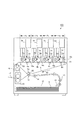
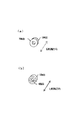
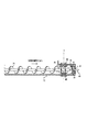
図1は画像形成装置の構成の説明図である。図1に示すように、画像形成装置100は、中間転写ベルト5に沿ってイエロー、マゼンタ、シアン、ブラックの画像形成部Pa、Pb、Pc、Pdを配列したタンデム型中間転写方式のフルカラープリンタである。
<Image forming apparatus>
FIG. 1 is an explanatory diagram of the configuration of the image forming apparatus. As shown in FIG. 1, the
中間転写ベルト5は、ローラ61、62、63に懸架され、矢印R2方向に移動自在とされる。画像形成部Paでは、感光ドラム1aにイエロートナー像が形成されて中間転写ベルト5に転写される。画像形成部Pbでは、感光ドラム1bにマゼンタトナー像が形成されて中間転写ベルト5に転写される。画像形成部Pc、Pdでは、それぞれ感光ドラム1c、1dにシアントナー像、ブラックトナー像が形成されて中間転写ベルト5に転写される。
The
中間転写ベルト5に転写された四色のトナー像は、二次転写部T2へ搬送されて記録材Pへ二次転写される。ピックアップローラ13によって記録材カセット12から取り出された記録材Pは、分離ローラ11で1枚ずつに分離して、レジストローラ14へ給送される。レジストローラ14は、中間転写ベルト5のトナー像にタイミングを合わせて二次転写部T2へ記録材Pを送り出す。トナー像を転写された記録材Pは、定着装置16で加熱加圧を受けて、表面にトナー像を定着された後に、排出トレイ17へ排出される。
The four-color toner images transferred to the
画像形成部Pa、Pb、Pc、Pdは、現像装置4a、4b、4c、4dで用いるトナーの色が異なる以外は、ほぼ同一に構成される。以下では、画像形成部Paについて説明し、画像形成部Pb、Pc、Pdについては、画像形成部Paの構成部材に付した符号末尾のaをb、c、dに読み替えて説明されるものとする。
The image forming portions Pa, Pb, Pc, and Pd are substantially the same except that the toner colors used in the developing
画像形成部Paは、感光ドラム1aの周囲に、コロナ帯電器2a、露光装置3a、現像装置4a、一次転写ローラ6a、ドラムクリーニング装置19aを配置している。
In the image forming portion Pa, a
感光ドラム1aは、アルミニウムシリンダの外周面に負極性の帯電極性を持たせた感光層が形成され、所定のプロセススピードで矢印方向に回転する。コロナ帯電器2aは、感光ドラム1aの表面を一様な負極性の暗部電位VDに帯電させる。露光装置3aは、レーザービームを回転ミラーで走査して、帯電した感光ドラム1aの表面に画像の静電像を書き込む。現像装置4aは、トナーとキャリアを含む現像剤を用いて、静電像を現像して、感光ドラム1aの表面にトナー像を形成する。
The
一次転写ローラ6aは、中間転写ベルト5の内側面を押圧して、感光ドラム1aと中間転写ベルト5との間にトナー像の転写部を形成する。一次転写ローラ6aに正極性の直流電圧を印加することにより、感光ドラム1aに担持された負極性のトナー像が中間転写ベルト5へ一次転写される。ドラムクリーニング装置19aは、記録材Pへの転写を逃れて感光ドラム1aに残った転写残トナーを回収する。
The
なお、像担持体として、通常使用されるドラム状の有機感光体である感光ドラム1aを使用したが、アモルファスシリコン感光体等の無機感光体を使用してもよく、ベルト状の感光体を用いることも可能である。帯電方式、現像方式、転写方式、クリーニング方式、定着方式に関しても、上記方式に限られるものではない。
Although the
<現像装置>
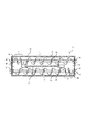
図2は長手方向に垂直な断面における現像装置の構成の説明図である。図3は長手方向に沿った断面における現像装置の構成の説明図である。図2に示すように、現像装置4aは、現像スリーブ28にトナーとキャリアを含む現像剤を担持して感光ドラム1aの静電像を現像する。感光ドラム1aは、矢示R1方向に273mm/secのプロセススピード(周速度)で回転する。現像装置4aは、現像剤として非磁性トナーと磁性キャリアとを混合した二成分現像剤を使用する。
<Developing device>
FIG. 2 is an explanatory diagram of the configuration of the developing device in a cross section perpendicular to the longitudinal direction. FIG. 3 is an explanatory diagram of the configuration of the developing device in a cross section along the longitudinal direction. As shown in FIG. 2, the developing
現像容器22は、現像スリーブ28に現像剤を供給する現像室23と現像スリーブ28から現像剤を回収する攪拌室24とを縦に並べて配置する。現像容器22の感光ドラム1aに対向する領域に現像スリーブ28が回転可能に配置されている。
In the developing
図3に示すように、現像容器22を隔壁27で仕切って構成される現像室23と攪拌室24は、現像剤を攪拌しつつ搬送する現像剤の循環経路を構成している。現像室23の下方に攪拌室24が配置され、現像室23には現像スクリュー25が回転可能に設けられ、攪拌室24には攪拌スクリュー26が回転可能に設けられている。現像スクリュー25と攪拌スクリュー26は、現像室23と攪拌室24の現像剤を逆方向に搬送して、現像容器22内を循環させる。隔壁27は、長手方向の両端部で垂直方向に現像剤を受け渡す開口部11、12を設けられている。
As shown in FIG. 3, the developing
図2に示すように、現像スリーブ28は、アルミニウムやステンレスのような非磁性材料で構成され、直径が20mmである。感光ドラム1の直径は80mm、現像部における現像スリーブ28と感光ドラム1との最近接領域は約300μmである。これにより、現像部に搬送した現像剤を磁気ブラシ状態で感光ドラム1と接触させて現像が行なえるように設定されている。
As shown in FIG. 2, the developing
現像領域において、現像スリーブ28は、感光ドラム1aの表面の移動方向と順方向で回転し、対感光ドラム周速比は、1.75倍である。対感光ドラム周速比は、大きいほど現像効率がアップするが、大き過ぎるとトナー飛散、現像剤劣化等が発生するため、0.5〜2.0倍の間に設定することが好ましい。
In the developing region, the developing
現像スリーブ28の内側には、表面に複数の磁極N1、S1、N3、N2、S2、N3を配置して非回転に支持されたマグネットローラ29が配置される。現像極S2は、現像部における感光ドラム1に対向して配置される。磁極S1は、規制ブレード30に対向して配置される。磁極N2は、磁極S1、S2の間に配置される。磁極N1及びN3は、現像室23及び攪拌室24にそれぞれ対向して配置される。各々の磁極の磁束密度の大きさは40mT〜70mTとしたが、現像に供されるS2極は100mTとした。
Inside the developing
現像スリーブ28は、矢印R28方向に回転し、感光ドラム1aに対向する現像領域の回転方向上流に層厚規制ブレード30が配置される。層厚規制ブレード30は、現像スリーブ28に担持される磁気ブラシの穂切りによって、現像剤の層厚を規制している。
The developing
規制ブレード30は、現像スリーブ28の長手方向に配置した非磁性の金属板(アルミニウム)であって、規制ブレード30の先端部と現像スリーブ28との間を現像剤が通過して現像領域へ送られる。
The regulating
規制ブレード30の先端と現像スリーブ28の表面とのギャップを調整することによって、現像スリーブ28に担持されて現像領域へ搬送される現像剤量が調整される。ここでは、規制ブレード30と現像スリーブ28のギャップを500μmに設定して、現像スリーブ28上の単位面積当りの現像剤コート量を30mg/cm2に調整している。規制ブレード30と現像スリーブ28のギャップは、200〜1000μm、好ましくは300〜700μmに設定される。
By adjusting the gap between the tip of the
二成分磁気ブラシ現像法において、現像剤は、現像時に、磁性体のキャリアがマグネット29の磁極間に形成された磁束に拘束されて現像スリーブ28の表面に担持される。現像スリーブ28の表面では、正極性に帯電したキャリアの表面に負極性に帯電したトナーが静電気的に拘束されて磁気ブラシを形成する。
In the two-component magnetic brush development method, the developer is carried on the surface of the developing
現像スリーブ28は、現像剤を担持して、感光ドラム1aと対向した現像領域に搬送する。現像電源D28は、現像効率(静電像へのトナーの付与率)を向上させるために、−500Vの直流電圧に、ピーク・ツウ・ピーク電圧Vpp=800V、周波数f=12kHzの交流電圧を重畳した現像電圧を現像スリーブ28に印加する。また、一般に、交流電圧を印加すると現像効率が増して画像は高品位になるが、逆に白地かぶりトナーが発生し易くなる。このため、現像スリーブ28に印加する直流電圧と感光ドラム1aの帯電電位(即ち白地部電位)との間に電位差を設けることにより、白地かぶりトナーを防止している。しかし、直流電圧、交流電圧の組み合わせは、これに限られるものではない。
The developing
<現像剤>
現像剤は、絶縁性の非磁性トナーと、磁性粒子(キャリア)とからなる二成分現像剤であり、非磁性トナーとしては、重量平均粒径4μm以上10μm以下のものが好適である。ここでは、重量平均粒径が8μmのカラー複写機用トナーを用いた。
<Developer>
The developer is a two-component developer composed of an insulating nonmagnetic toner and magnetic particles (carrier), and the nonmagnetic toner preferably has a weight average particle diameter of 4 μm or more and 10 μm or less. Here, a toner for a color copying machine having a weight average particle diameter of 8 μm was used.
トナーの重量平均粒径をMとし、トナーの粒径をrとする。このとき、より鮮明なカラー像を形成するためには、1/2M<r<2/3Mの範囲に90重量%以上のトナー粒子が含まれ、0<r<2Mの範囲に99重量%以上のトナー粒子が含まれていることが好ましい。 Let M be the weight average particle diameter of the toner and r be the particle diameter of the toner. At this time, in order to form a clearer color image, 90% by weight or more of toner particles are included in the range of 1 / 2M <r <2 / 3M, and 99% by weight or more in the range of 0 <r <2M. The toner particles are preferably contained.
トナーの粒度分布及び重量平均粒径は、以下のように測定した。測定装置としては、コールター社製のコールターカウンターTA−II型を用い、個数平均分布、重量平均分布を出力するために、日科機製のインターフェイス及び市販のパーソナルコンピュータを接続した。 The particle size distribution and the weight average particle size of the toner were measured as follows. As a measuring device, a Coulter counter TA-II type manufactured by Coulter Co. was used, and an interface made by Nikki and a commercially available personal computer were connected to output the number average distribution and the weight average distribution.
測定用の電解液は、1級塩化ナトリウムを用いて1%NaCl水溶液を調製した。電解水溶液100〜150ml中に、分散剤として界面活性剤(好ましくはアルキルベンゼンスルホン酸塩)0.1〜5mlを加え、測定試料0.5〜50mgを加えた。 As an electrolyte for measurement, a 1% NaCl aqueous solution was prepared using first grade sodium chloride. In 100 to 150 ml of the electrolytic aqueous solution, 0.1 to 5 ml of a surfactant (preferably alkylbenzene sulfonate) was added as a dispersant, and 0.5 to 50 mg of a measurement sample was added.
試料を懸濁した電解液は、超音波分散器で約1〜3分間分散処理を行い、コールターカウンターTA−II型により100μmアパーチャを用いて2〜40μmの粒子の粒度分布を測定した。そして、求めた粒度分布より、サンプルの重量平均粒径を演算した。 The electrolyte solution in which the sample was suspended was subjected to dispersion treatment for about 1 to 3 minutes with an ultrasonic disperser, and the particle size distribution of 2 to 40 μm particles was measured using a Coulter counter TA-II type with a 100 μm aperture. And the weight average particle diameter of the sample was calculated from the obtained particle size distribution.
トナーは、着色樹脂粒子(結着樹脂、着色剤、必要によりその他の添加剤を含有)そのもの、及び疎水性コロイダルシリカ微粉末の如き外添剤が外添されている着色樹脂粒子を包含している。 The toner includes colored resin particles (containing a binder resin, a colorant, and other additives as necessary) itself, and colored resin particles to which external additives such as hydrophobic colloidal silica fine powder are externally added. Yes.
トナーに使用される結着樹脂としては、スチレン−アクリル酸エステル樹脂、又はスチレン−メタクリル酸エステル樹脂の如きスチレン系共重合体又はポリエステル樹脂が例示される。カラートナーの定着時における混色性を考慮した場合、ポリエステル樹脂がシャープな溶融特性を有するので好ましい。 Examples of the binder resin used in the toner include styrene copolymers or polyester resins such as styrene-acrylic acid ester resins or styrene-methacrylic acid ester resins. In consideration of color mixing at the time of fixing the color toner, the polyester resin is preferable because it has a sharp melting characteristic.
一方、磁性キャリアは、重量平均粒径30〜80μm、好ましくは40〜70μmで、ここでは、重量平均粒径50μmのものを用いた。また、磁性キャリアの抵抗値は、1×10⁷Ωcm以上、好ましくは1×10⁸Ωcm以上、更に好ましくは1×10⁹〜1×10¹²Ωcmのものが好ましい。このようなキャリア粒子としては、フェライト粒子(最大磁化230emu/cm3程度のCu−Znフェライト)、又はこれに薄く樹脂コーティングしたものを良好に使用できる。 On the other hand, the magnetic carrier has a weight average particle diameter of 30 to 80 μm, preferably 40 to 70 μm, and here, a carrier having a weight average particle diameter of 50 μm was used. The resistance value of the magnetic carrier is preferably 1 × 10 7 Ωcm or more, preferably 1 × 10 8 Ωcm or more, and more preferably 1 × 10 9 to 1 × 10 12 Ωcm. As such carrier particles, ferrite particles (Cu—Zn ferrite having a maximum magnetization of about 230 emu / cm 3 ) or those thinly coated with a resin can be used favorably.
キャリアの重量平均粒径を測定するために、最初にキャリアの粒度分布を測定した。
1.試料約100gを0.1gの桁まで計り取る。
2.篩は、100メッシュから400メッシュの標準篩を用いた。標準篩の枠の寸法は、篩面から上の内径が200mm、上面から篩面までの深さが45mmである。標準篩は、上から100、145、200、250、350、400の順に積み重ね、底に受け皿を置き、試料は一番上の篩に入れてふたをした。
3.これを振動機によって水平旋回数毎分285±6回、摺動回数毎分150±10回で15分間ふるう。
4.ふるった後、各篩及び受け皿内の鉄粉を0.1gの桁まで計り取る。
5.重量百分率で少数第2位まで算出し、JIS−Z8401によって少数第1位まで丸める。このとき、各部分のキャリア粒子の重量の総和は、始めに取った試料の質量の99%以下であってはならない。
In order to measure the weight average particle size of the carrier, the particle size distribution of the carrier was first measured.
1. Weigh out approximately 100 g of sample to the nearest 0.1 g.
2. As the sieve, a standard sieve of 100 to 400 mesh was used. The standard sieving frame has an inner diameter of 200 mm above the sieving surface and a depth from the upper surface to the sieving surface of 45 mm. The standard sieves were stacked in the order of 100, 145, 200, 250, 350, 400 from the top, a saucer was placed on the bottom, and the sample was put on the top sieve and covered.
3. This is shaken by a vibrator at a speed of 285 ± 6 times per minute and 150 ± 10 times per minute for 15 minutes.
4). After sieving, the iron powder in each sieve and tray is weighed to the nearest 0.1 g.
5. Calculate to the second decimal place by weight percentage and round to the first decimal place according to JIS-Z8401. At this time, the sum of the weights of the carrier particles in each portion should not be less than 99% of the mass of the sample taken first.
平均粒径は、上述の粒度分布測定値より、下式に従って求める。
平均粒径(μ)=(1/100)×{(100メッシュ篩の残量)×140+(145メッシュ篩の残量)×122+(200メッシュ篩の残量)×90+(250メッシュ篩の残量)×68+(350メッシュ篩の残量)×52+(400メッシュ篩の残量)×38+(全篩通過量)×17}
The average particle diameter is determined according to the following formula from the measured particle size distribution.
Average particle size (μ) = (1/100) × {(100 mesh sieve remaining amount) × 140 + (145 mesh sieve remaining amount) × 122 + (200 mesh sieve remaining amount) × 90 + (250 mesh sieve remaining) Amount) × 68 + (remaining amount of 350 mesh sieve) × 52 + (remaining amount of 400 mesh sieve) × 38 + (total sieve passing amount) × 17}
キャリアの500メッシュ以下の部分の量は、50gの試料量を500メッシュ標準篩上に乗せて下から吸引して重量減少から算出した。 The amount of the carrier having a mesh size of 500 mesh or less was calculated from the weight reduction by placing a 50 g sample on a 500 mesh standard sieve and sucking it from below.
キャリア(フェライト粒子又は樹脂コートされたフェライト粒子)の抵抗値は、測定電極面積4cm2、電極間間隙0.4cmのサンドイッチタイプのセルを用いて測定した。セルの片方の電極に10N(1kgf)の加圧下で、両電極間の印加電圧E(V/cm)を印加して、回路に流れた電流から磁性粒子の抵抗値を測定した。 The resistance value of the carrier (ferrite particles or resin-coated ferrite particles) was measured using a sandwich type cell having a measurement electrode area of 4 cm 2 and a gap between the electrodes of 0.4 cm. The applied voltage E (V / cm) between the two electrodes was applied to one electrode of the cell under a pressure of 10 N (1 kgf), and the resistance value of the magnetic particles was measured from the current flowing through the circuit.
<樹脂磁性キャリア>
キャリアとしては、バインダ樹脂と磁性金属酸化物及び非磁性金属酸化物からなる樹脂磁性キャリアを重合法により生成したものを用いてもよい。樹脂磁性キャリアは、フェライト粒子に比べて最大磁化が小さく、190emu/cm3程度であることが特徴である。そのため、隣り合う磁気ブラシの磁気的な相互作用が小さく、その結果磁気ブラシの穂が緻密に且つ短くなることで、画像としてはきめムラ等のない解像度が高いものを提供できる。
<Resin magnetic carrier>
As the carrier, a resin magnetic carrier made of a binder resin, a magnetic metal oxide, and a nonmagnetic metal oxide may be used which is generated by a polymerization method. The resin magnetic carrier is characterized in that the maximum magnetization is smaller than that of the ferrite particles and is about 190 emu / cm 3 . For this reason, the magnetic interaction between adjacent magnetic brushes is small, and as a result, the ears of the magnetic brushes become dense and short, so that an image having high resolution with no texture unevenness can be provided.
一方、磁化は、磁性キャリアがマグネットによって磁化される程度を表し、小さいほど磁化されづらく、マグネットへの拘束力も小さい。そのため、マグネットが拘束できる現像剤総量も少なく、従来の構成では、拘束しきれなくなった現像剤が軸受け側に漏れ出し易い。 On the other hand, the magnetization indicates the degree to which the magnetic carrier is magnetized by the magnet. The smaller the magnetization, the harder it is to magnetize, and the smaller the binding force to the magnet. Therefore, the total amount of developer that can be restrained by the magnet is small, and in the conventional configuration, the developer that cannot be restrained easily leaks to the bearing side.
本発明の構成に拠れば、このような樹脂磁性キャリアを用いた場合でも、拘束しきれなくなった現像剤が順次攪拌スクリューで戻されるので、長時間にわたり軸受け部への現像剤侵入防止の効果が得られる。 According to the configuration of the present invention, even when such a resin magnetic carrier is used, the developer that can no longer be constrained is sequentially returned by the stirring screw, so that the effect of preventing the developer from entering the bearing portion for a long time is obtained. can get.
磁化量の算出法であるが、キャリアの磁気特性を理研電子(株)製の振動磁場型磁気特性自動記録装置にて、1KOe(キロエルステッド)の外部磁場中に円筒状にパッキングしたキャリアの磁化の強さを求めた。その後キャリアの真比重を掛けることで磁化量(emu/cm3)を算出した。 Magnetization of a carrier packed in a cylindrical shape in an external magnetic field of 1 KOe (kiloelsted) with a magnetic field automatic magnetic recording device manufactured by Riken Denshi Co., Ltd. Sought the strength of. Thereafter, the amount of magnetization (emu / cm 3 ) was calculated by multiplying the true specific gravity of the carrier.
<比較例>
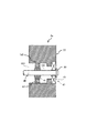
図4は比較例の攪拌スクリュー端部の軸受け構造の説明図である。一般的な現像装置は、現像容器中の現像剤を攪拌しながら現像剤担持体へ向かって搬送する攪拌部材を有する。攪拌部材としては、スクリューやフィン付軸のような回転部材が用いられている。回転部材は、現像容器の側壁に設けられた現像剤面よりも低い軸受け部に支持されているため、軸受け部には、現像剤の漏れ出しを阻止するためのシール構成が不可欠である。
<Comparative example>
FIG. 4 is an explanatory view of the bearing structure of the end of the stirring screw of the comparative example. A typical developing device has an agitating member that conveys the developer in the developing container toward the developer carrying member while stirring. As the stirring member, a rotating member such as a screw or a finned shaft is used. Since the rotating member is supported by a bearing portion lower than the developer surface provided on the side wall of the developing container, a seal configuration for preventing leakage of the developer is indispensable in the bearing portion.
現像剤面よりも低い軸受けにブッシングを使用した場合、現像装置の使用初期においては現像剤のシール効果は保てるが、現像動作を繰り返すにつれて、現像剤の循環する圧力によって回転軸とブッシングとの摺擦面に現像剤が徐々に侵入する。その結果、侵入した現像剤が溶融固着して回転軸の駆動トルクを増加させたり、回転軸とブッシングの摺擦面が摩耗したり、摩擦熱で溶融した現像剤が凝集塊を作って、現像剤に混合して出力画像の品質を低下させる問題があった。 When a bushing is used for a bearing lower than the developer surface, the developer sealing effect can be maintained in the initial stage of use of the developing device, but as the developing operation is repeated, the sliding between the rotating shaft and the bushing is caused by the circulating pressure of the developer. The developer gradually enters the rubbing surface. As a result, the invading developer melts and adheres to increase the driving torque of the rotating shaft, the rubbing surface of the rotating shaft and bushing wears, or the developer melted by frictional heat forms agglomerates and develops. There is a problem that the quality of the output image is deteriorated by mixing with an agent.
ブッシングのシール性を高めるためには、回転軸に対する密着性を大きくすればよいが、密着性を大きくすると回転軸に大きな力が加わって駆動モーターの負荷が増大して摩擦熱によるトナーの溶融も深刻になる。また、近年、高画質を得るためにトナーが小径化されて、密着性に頼ってシール性を高めることはさらに困難になっている。 In order to improve the sealing performance of the bushing, it is sufficient to increase the adhesion to the rotating shaft. However, if the adhesion is increased, a large force is applied to the rotating shaft, the load on the drive motor increases, and the toner melts due to frictional heat. Become serious. In recent years, the diameter of toner has been reduced in order to obtain high image quality, and it has become more difficult to increase the sealing performance by relying on the adhesion.
軸受けにボールベアリングを使用した場合も、ボールベアリング内へ現像剤が侵入して同様な問題を引き起こした。更に、ベアリングのシール部より漏洩するベアリングオイルによって現像剤が溶融凝集したり、ベアリング内に侵入した現像剤とベアリングオイルが溶融固着しベアリングがロックしたりすることもあった。 When a ball bearing was used for the bearing, the developer entered the ball bearing and caused the same problem. Further, the developer may be melted and aggregated by the bearing oil leaking from the seal portion of the bearing, or the developer and the bearing oil entering the bearing may be melted and fixed to lock the bearing.
オイルシールは、ブッシングやボールベアリングと比較して現像剤のシール効果に優れている。しかし、オイルシールは、耐久性に欠け、回転軸との摺擦が繰り返されるにつれて当接部が摩耗損傷し、現像剤の循環する圧力により、当接部が押されて変形し、シール効果が薄れるとブッシングやボールベアリングと同様の問題が生じた。 The oil seal is more excellent in the developer sealing effect than the bushing or ball bearing. However, the oil seal lacks durability, and the abutting portion is worn and damaged as the rubbing with the rotating shaft is repeated, and the abutting portion is pushed and deformed by the circulating pressure of the developer, resulting in a sealing effect. When thinned, problems similar to bushings and ball bearings occurred.
図3に示すように、現像スクリュー25及び攪拌スクリュー26のそれぞれの両端に位置する現像容器22の4個の軸受け部41に、それぞれ磁気シール付きの軸受けを装備した。
As shown in FIG. 3, the four bearing
図4に示すように、軸受け部41は、ボールベアリング42を現像容器22に取り付けた内側に円柱状の空間48Bを形成し、空間48Bの入口にリング状の磁石部材43を設けている。リング状の磁石部材43によって現像剤の磁気ブラシMBを形成させて、回転軸40に磁気ブラシMBを摺擦させてボールベアリング42側へ現像剤が侵入することを防ぐ仕組みである。
As shown in FIG. 4, the bearing
回転軸40は、磁石部材43が対向する部分が磁性体材料で形成され、磁石部材43によって磁化される。磁石部材43と回転軸40の間に形成される磁界によって、現像剤の磁気ブラシMBを形成し、磁気ブラシMBが現像剤がボールベルリング41側へ現像剤が漏出することを防止している。
The rotating
軸受け部41では、磁石部材43と回転軸40との間に磁束が集中し、磁束に沿ってキャリアが立ち上がって磁気ブラシMBを形成し、外側へ向かうボールベアリング42の手前側が磁気ブラシMBのカーテンでシールされる。磁気ブラシMBは、回転軸40の回転に伴い、その一部が磁石部材43に拘束された状態で、残りの一部が回転軸40と共に連れ回る。このため、軸受け部41での現像剤の摺擦は、現像剤同士のソフトな摺擦となって温度が低く保たれ、現像剤はトナーの溶融による微小な凝固体を形成することなく、良好なシール性能を発揮する。
In the bearing
比較例では、軸受け部41の回転軸40の内側部分にリング状の磁石部材43を設けて磁気ブラシMBを形成することで、ボールベアリング42への現像剤の侵入を抑制できる。しかし、現像剤が徐々にボールベアリング42側に漏れ出すことは避け難い状況にある。そのため、長時間使用する中では、ボールベアリング42で現像剤が問題を引き起こす可能性がある。
In the comparative example, the intrusion of the developer into the
現像スクリュー25や攪拌スクリュー26の搬送方向の下流側では、スクリュー羽根によって搬送される現像剤が間欠的にせき止められて大きな圧力変動が発生する。このため、比較例の磁気シールでは、磁石部材43と回転軸40との間に形成される現像剤の磁気ブラシに大きな圧力変動が作用して、外側への膨らみと収縮を繰り返す。その結果、磁気ブラシからトナー粒子が脱落してボールベアリング42側へ漏れ出してしまう。
On the downstream side in the conveying direction of the developing
比較例では、磁石部材43に現像剤が侵入しにくくなるように、磁石部材43よりも上流側に、現像剤を磁石部材43から離れる方向に搬送する逆搬送スクリュー45を設けている。逆搬送スクリュー45は、現像剤が軸受け部41に到着するまでの時間を遅らせることは可能であるが、摺擦負荷によるトルクアップや現像剤劣化の懸念があるため、逆搬送スクリュー45の稜線と現像容器22の内壁面との間に一定の隙間を設ける必要がある。その結果、この隙間を通過して軸受け部41に現像剤が到達することを防ぎきることができず、現像装置4aを長時間使用することを考えると、軸受け部41への現像剤の進入を防ぎ得ない。
In the comparative example, a
現像装置4aを長期間使用するなかで、磁石部材43に拘束された現像剤の一部が徐々にボールベアリング42側に漏れ出していた。磁石部材43が拘束できる現像剤量に限界があるにもかかわらず、回転軸40に沿った方向の現像剤の圧力によって、内側から磁石部材43へ恒常的に少しずつ現像剤が侵入する。このため、磁石部材43が拘束しきれなくなった現像剤の一部がボールベアリング42側に落下していた。
While the developing
外側へ向かう現像剤の圧力が磁気ブラシに直接作用するため、現像装置4aを長期間使用するなかで、円筒状の磁石部材43に拘束された現像剤が徐々にボールベアリング42側に漏れ出していた。磁石部材43を強くしても、現像剤の漏れ出しを、完全に防止することは難しかった。
Since the developer pressure toward the outside acts directly on the magnetic brush, the developer restrained by the
また、近年、高画質を達成するために、飽和磁化量が比較的小さい(例えば190emu/cm3以下)の磁性キャリアが二成分現像剤に使用されるようになった。一成分現像剤においても、高画質を達成するために、飽和磁化量が従来よりも小さい磁性トナーが採用されている。 In recent years, in order to achieve high image quality, a magnetic carrier having a relatively small saturation magnetization (for example, 190 emu / cm 3 or less) has been used for a two-component developer. Even in the one-component developer, in order to achieve high image quality, a magnetic toner having a saturation magnetization smaller than that of the conventional toner is employed.
現像剤粒子の飽和磁化量が小さくなると、現像剤が磁石部材43に拘束される力が小さくなるため、長期間使用するなかで、現像剤がボールベアリング42側に漏れ出し易くなる。
When the saturation magnetization amount of the developer particles is reduced, the force with which the developer is restrained by the
ここで、磁石部材43の磁力を高めることができれば、現像剤を強固に保持して圧力に抵抗し、ボールベアリング42側への漏れ出しを回避できる。しかし、磁石部材43の磁力を高めるには、大型化もしくはコスト高を伴う。近年、現像装置の小型化が進められた結果、大きな磁石部材43を軸受け部41に設けることは不可能になっている。コスト高も容認できない。
Here, if the magnetic force of the
また、ボールベアリング42と磁石部材43の間隔を大きくして十分な空間48Bを確保すれば、現像剤がボールベアリング42側に漏れ出しても、ボールベアリング42まで到着するのを遅らせることができる。しかし、得られる効果はあくまで延命効果のみで、漏れ出す課題の本質的な解決にはなっていないし、現像装置の大型化、コスト高に繋がる懸念もある。
Further, if a
そこで、以下の実施例では、回転軸40を囲む磁石部材43の中心にスクリューを設けて外側から内側へ向かう付勢力を発生させて、現像容器22内の現像剤が磁気ブラシMBに及ぼす圧力に対抗させている。これにより、磁石部材43の磁力を高めることなく、内側からの現像剤の圧力に抵抗し、ボールベアリング42側への漏れ出しを回避している。
Therefore, in the following embodiment, a screw is provided at the center of the
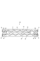
<実施例1>
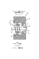
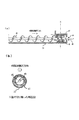
図5は実施例1の攪拌スクリュー端部の軸受け構造の説明図である。図6は磁石部材の着磁パターンの説明図である。図3に示すように、現像スクリュー25及び攪拌スクリュー26の両端を支持する現像容器22の4個の軸受け部41に、それぞれ磁気シール付きの軸受けを装備した。図5は、図3で点線で囲んで示した攪拌スクリュー26の下流側の領域Aの軸受け部41を含む現像容器22の壁内構造を拡大して示している。以下では、領域Aについて説明するが、現像スクリュー25と攪拌スクリュー26の両端部に対応する他の軸受け部(点線で囲われた領域)41についても、同様に図5に示すように構成されている。
<Example 1>
FIG. 5 is an explanatory diagram of the bearing structure of the end of the stirring screw according to the first embodiment. FIG. 6 is an explanatory diagram of the magnetization pattern of the magnet member. As shown in FIG. 3, the four bearing
図5に示すように、搬送部材の一例である攪拌スクリュー26は、磁性粒子を含む現像剤を収納する現像容器22に形成された循環経路内の現像剤を循環搬送させる。軸受け部41は、攪拌スクリュー26を回転可能に支持する。磁石部材の一例である磁石部材43は、軸受け部41より循環経路側で回転軸40を囲むように配置され、搬送部の一例であるスクリュー羽根44と現像容器22との間隙に磁界を形成することで現像剤の磁気ブラシを形成する。スクリュー羽根44は、軸受け部41よりも循環経路側において、循環経路外から循環経路内に向けて現像剤を搬送する。スクリュー羽根44は、磁石部材43によってその内周面側に形成される現像剤の磁気ブラシと干渉するように回転軸40に固定して設けられ、攪拌スクリュー26の回転に伴って磁気ブラシの現像剤を循環経路外から循環経路内に向けて攪拌する。
As shown in FIG. 5, the
スクリュー羽根44は、磁石部材43によって形成された磁気ブラシが干渉する干渉部が設けられ、干渉部よりも循環経路側とその反対側とに磁気ブラシが干渉しない非干渉部とが設けられている。非干渉部から干渉部を経て非干渉部へ現像剤が撹拌及び搬送されることで、磁気ブラシの全体に渡って、現像剤の入れ替わりを助けている。
The
現像容器22は、軸受け部41と磁石部材43との間に、磁気ブラシによって現像容器内の現像剤から遮断される空間48Bを形成されている。スクリュー羽根44は、回転軸40に沿った少なくとも片側で磁石部材43の外側にはみ出して配置される。
In the developing
少なくとも磁石部材43に対向する領域では、回転軸40が強磁性体材料で形成され、スクリュー羽根44が非磁性材料で形成される場合、攪拌スクリュー26の回転負荷が軽減される。一方、少なくとも磁石部材43に対向する領域では、回転軸及びスクリュー羽根44がいずれも強磁性体材料で形成される場合、磁気ブラシによるシール性能が強化される。
At least in the region facing the
図5に示すように、攪拌スクリュー26の回転軸40の端部は、ボールベアリング42を備えた軸受け部41を介して現像容器22の側壁に回転自在に支持されている。回転軸40は、鉄、コバルト或いはニッケル、又はそれらの合金による強磁性体材料で作製される。通常、製造コストが安い点から、回転軸40は、鉄で製作することが好ましい。回転軸40の軸方向の移動は、ボールベアリング42の外側で、ストップリング50によって規制されている。
As shown in FIG. 5, the end of the
回転軸40の軸受け部41は、合成樹脂等の非磁性体材料で構成された現像容器22の壁厚内に組み立てられている。軸受け部41は、ボールベアリング42を現像容器22に取り付けた内側に円柱状の空間48Bが形成され、空間48Bの入口にリング状の磁石部材(リング状マグネット)43が固定されている。磁石部材43は、厚み3mm、内径11mm、外径15mmの円筒型形状である。
The bearing
磁石部材43を貫通して配置された回転軸40には、部分的な螺旋状のスクリュー羽根44が設けられている。スクリュー羽根44は、非磁性の樹脂材料であるABS樹脂を用いて回転軸40と一体に射出成形した。スクリュー羽根44は、軸径3mmの回転軸40の外側を一体に覆った樹脂材料で形成され、外径9mm、ピッチ2mmの螺旋状の形状である。したがって、磁石部材43は、内周面が1mmの間隙を介してスクリュー羽根44の外周と対向している。
The rotating
スクリュー羽根44の螺旋の巻き方向は、スクリュー羽根44の回転に伴って、現像剤が回転軸40方向でボールベアリング42側から現像容器22の内側方向に搬送されるように巻いておくことが、必要な条件である。
The spiral direction of the
磁石部材43は、希土類の合金粉を結着したプラスチックマグネットで形成され、最大磁気エネルギー積(B・H)maxが7.0(MOe)である。磁石部材43の表面磁束密度は少なくとも60ミリテスラ以上が好ましい。
The
図6の(a)に示すように、磁石部材43は、円筒状の厚み方向(回転軸40の軸方向)に磁束を形成するように着磁されている。磁石部材43は、現像容器22の内側に面した内側面がN極に、ボールベアリング42に対面する外側面がS極に着磁されている。
As shown in FIG. 6A, the
ただし、着磁パターンは、磁石部材43の内側の円筒面に回転軸40へ向かう磁気ブラシを形成できるものであればよく、図6の(a)において内側面をN極に、外側面をS極に着磁してもよい。図6の(b)に示すように、軸方向ではなくて半径方向にS、NにまたはN、Sに着磁してもよい。
However, the magnetizing pattern is not limited as long as it can form a magnetic brush toward the rotating
図5に示すように、磁石部材43は、スクリュー羽根44に近接対向しており、スクリュー羽根44および回転軸40は、磁石部材43が形成する磁界内に位置するように配置されている。磁石部材43の磁界内に回転軸40を配置することにより、強磁性体材料の回転軸40が磁化され、強磁性体材料の回転軸40と磁石部材43との間に磁気回路が形成される。
As shown in FIG. 5, the
磁気回路では、磁石部材43の両磁極N、S間に伸びる磁力線の多くが回転軸40に向かって伸びるので、磁石部材43と回転軸40との間に回転軸40に対して立った状態の磁力線が増加する。
In the magnetic circuit, most of the magnetic lines of force extending between the magnetic poles N and S of the
磁性キャリアを含む現像剤は、磁力線の集中した場所で概ね磁力線に沿って磁気ブラシを形成するので、磁石部材43と回転軸40との間の空隙部gには、現像剤による密な磁気ブラシmが集中して形成される。そして、強い集中磁界中で形成された密な磁気ブラシmの内側で、回転軸40と回転軸40に配置されたスクリュー羽根44とが一体に回転する。磁石部材43に形成される磁気ブラシの長さは、スクリュー羽根44と磁石部材43の間隙よりも長く形成されるため、間隙を磁気ブラシによって埋めて、高いシール性を発揮できる。
Since the developer including the magnetic carrier forms a magnetic brush substantially along the magnetic field lines at the location where the magnetic field lines are concentrated, a dense magnetic brush made of the developer is formed in the gap g between the
このようにして、円筒形状の磁石部材43の内側面には、磁石部材43と回転軸40の間隙部、および磁石部材43とスクリュー羽根44の間隙部における高いシーリング性能が達成される。
In this way, high sealing performance is achieved on the inner surface of the
図4に示すように、回転軸40にスクリュー羽根が設けられていない比較例では、内側から外側へ向かう現像剤の圧力を緩和できないため、現像剤の漏れ出しを、完全に防止することは難しかった。磁石部材43へ恒常的に少しずつ侵入してくる現像剤を押し戻す手段がないため、現像剤の漏れ出しを防ぐことができなかった
これに対して、実施例1では、図5に示すように、スクリュー羽根44が回転に伴って現像剤を内側へ押し込んで内側から外側へ向かう現像剤の圧力を緩和するので、現像剤の漏れ出しが解消される。スクリュー羽根44が回転することで、現像剤を現像容器22内へ搬送する力が生じるので、磁石部材43に恒常的に現像剤が侵入しても、現像剤が徐々に現像容器22側へ押し戻される。
As shown in FIG. 4, in the comparative example in which the screw blades are not provided on the
なお、スクリュー羽根44は、軸方向の長さによらず、磁石部材43の内側の円筒面に対向していれば、内側から外側へ向かう現像剤の圧力に対抗し得る。しかし、図5に示すように、スクリュー羽根44の軸方向の長さをボールベアリング42側へ長くして、磁石部材43よりもはみ出させると、現像剤の漏れ出しの抑制効果が高まる。ボールベアリング42側へ現像剤の磁気ブラシが盛り上がった場合でも、こぼれ落ちる前に現像剤をスクリュー羽根44で現像容器22の内側へ戻し得るからである。
The
また、図5に示すように、スクリュー羽根44の軸方向の長さを現像容器22の内側方向へ長くして、磁石部材43よりも現像容器22の内側方向へはみ出させると、現像剤の漏れ出しの抑制効果が高まる。磁石部材43に拘束された現像剤をスクリュー羽根44で現像容器22側へ戻す際に、現像剤を戻して解放する位置が磁石部材43に近いと磁石部材43の磁力によって引き戻されてしまう。スクリュー羽根44が現像容器22の内側にはみ出ていると、磁石部材43の磁力が及ばない位置まで搬送して解放することで、スクリュー羽根44で現像剤を現像容器22へ戻す効率が高まるからである。
Further, as shown in FIG. 5, if the axial length of the
特に、回転軸40が強磁性体材料の場合、磁束は磁石部材43と回転軸40の対向する範囲に集中するため、磁石部材43の軸方向の内側から外側へ出ると磁束密度が急減する。そのため、磁石部材43の軸方向の長さから少しでも外側へ搬送すれば、搬送する現像剤を磁石部材43へ引き戻されることなく現像容器22内へ押し戻すことができる。磁石部材43の磁束は回転軸40方向に強く集中して伸びるので、磁石部材43の近傍では磁束密度が高く、現像剤に強い磁気引力が働く。しかし、磁石部材43から少しでも外側であれば、磁束が疎となって磁界の変化量も小さくなるため、現像剤に作用する磁気引力もほとんど無くなる。したがって、磁石部材43よりも少しでも外側まで現像剤を搬送してやれば、現像剤は磁石部材43に引き戻されにくくなる。
In particular, when the rotating
また、スクリュー羽根44の配された回転軸40は、ボールベアリング42とストップリング50の隙間t分、軸方向に多少のガタツキ幅を持たせてある。このようなガタツキ幅の存在により、スクリュー羽根44と磁石部材43とが軸方向に位置ずれした場合でも、上述の軸方向のはみ出しによる効果を確保する必要がある。そのためには、ガタツキ幅tよりもスクリュー羽根44のはみ出し量を大きくしておくことが必要である。
Further, the
以上を踏まえて、実施例1では、磁石部材43の厚みが2mmであるのに対して、長さ6mmのスクリュー羽根44を回転軸40方向に各2mmずつはみ出るように配置した。ガタツキ幅を1mmとして、はみ出し量を軸方向の前後に各2mmとした。
Based on the above, in Example 1, the thickness of the
また、スクリュー羽根44は、非磁性の樹脂材料で形成しても効果が得られるが、鉄のような強磁性体材料で形成すれば、さらに付加的な利点がある。スクリュー羽根44を強磁性体材料で形成した場合、磁石部材43と回転軸40の間だけでなく、磁石部材43とスクリュー羽根44の稜線との間にも磁気回路が形成される。円筒状の磁石部材43の内周面から伸びる磁力線が回転軸40だけでなくスクリュー羽根44にも向かって伸びるので、磁力線が増加する。
In addition, the
特に、スクリュー羽根44の先端に向かって磁力線が集中して形成されるため、磁石部材43とスクリュー羽根44の先端との空隙に現像剤による緻密な磁気ブラシが形成される。このため、磁石部材43とスクリュー羽根44との間隙では、磁気ブラシによる強固なシーリング性能が達成される。
In particular, since magnetic lines of force are concentrated toward the tip of the
ただし、金属材料によるスクリュー羽根44の削り出しはコスト高になるため、磁性体樹脂材料でスクリュー羽根44を形成してコストを削減してもよい。射出成型が可能な磁性体樹脂材料としては、鉄粉やフェライトを混合した樹脂材料が知られている。その他、樹脂で型成形した羽根に強磁性体材料の薄板を貼り付けたり、強磁性粉を吹き付けたりする方法でスクリュー羽根44を形成してもよい。
However, since the cutting of the
また、いわゆるスクリュー羽根の形状には限らず、螺旋溝で軸方向の現像剤の搬送性能を確保させてもよい。強磁性体金属材料の回転軸40そのものを螺旋状に切削加工して、削り跡を螺旋溝として利用することができる。削り跡の凹部を利用しているため、スクリュー-羽根ほどの搬送効果は得られないが、小口径のシール構造から漏れ出すわずかな現像剤を搬送する性能は十分に確保できる。
Further, the shape of the developer is not limited to the so-called screw blade shape, and the conveyance performance of the developer in the axial direction may be secured by a spiral groove. The rotating
実施例1のシール構造によれば、攪拌スクリュー26の長手方向端部からの現像剤の漏れ出しを防止して、長期間にわたり攪拌スクリュー26の駆動負荷の増大やトナー凝集隗の発生を防止することが可能である。逆搬送スクリュー45を単純に磁石部材43対向部の軸方向前後に設けても、逆搬送スクリュー45と現像容器22の隙間から現像剤が漏れ出して完全な対策ではなかった課題を解決できる。
According to the seal structure of the first embodiment, the leakage of the developer from the longitudinal end portion of the stirring
<実験結果>
図4の比較例と図5の実施例1とで比較実験を行った。まず、スクリュー羽根44を設けない比較例では、現像動作を繰り返したところ、少しずつではあるが、現像剤が磁石部材43による磁気シール部を抜けて、ボールベアリング42側に漏れ出した。現像装置4aの新品状態からの累積画像形成枚数50万枚付近で、ボールベアリング42のボールに付着した現像剤がボールの回転を妨げ、結局は回らなくなって停止した。停止の原因は過負荷による駆動ギヤの破損であった。
<Experimental result>
A comparative experiment was performed between the comparative example of FIG. 4 and the example 1 of FIG. First, in the comparative example in which the
スクリュー羽根44を設けた実施例1では、現像装置4aの新品状態からの累積画像形成枚数が100万枚を越えても、ボールベアリング42側への現像剤の漏れ出しはほとんど観察されず、正常な運転状態が確認された。
In Example 1 in which the
したがって、回転軸40における磁石部材43の対向部分にスクリュー羽根44を設けることで、磁石部材43に侵入した現像剤を現像容器22の内側へ向かって戻す効果が生まれることが確認された。比較例よりも、現像剤の漏れ出しを抑えた、耐久性のよりよい、現像装置4aを提供できることが確認された。
Therefore, it was confirmed that providing the
実施例1では、回転軸40と磁石部材(リング状マグネット)43の対向部分にスクリュー羽根44を設けることで、磁石部材43に侵入した現像剤を現像容器22の内側へ戻す効果が生まれる。これにより、比較例の磁気シールよりもよりも、現像剤の漏れ出しを抑えた、耐久性の高い現像装置を提供できる。
In the first embodiment, by providing the
実施例1では、軸受け部41よりも現像容器22の内側で回転軸40を包囲するように磁石部材43を配置し、磁石部材43に対向する位置にスクリュー羽根44を設けることで、軸受け部41への現像剤の漏れ出しを防止する。
In the first embodiment, the
実施例1では、磁性キャリアとトナーからなる二成分現像剤を用いた現像装置での応用例を説明したが、磁性トナーからなる一成分現像剤の場合でも、現像剤の界面下に配置される回転軸のシール構造に本発明を実施できる。一成分現像剤の場合は、磁性トナーの磁気ブラシが形成される点が異なるが、軸受け部の基本的な構成は二成分現像剤の場合と同一である。磁性キャリア、磁性トナー等、磁性粒子を含む現像剤であれば、本発明を実施できる。 In the first embodiment, the application example in the developing device using the two-component developer composed of the magnetic carrier and the toner has been described. The present invention can be implemented in the seal structure of the rotating shaft. In the case of a one-component developer, the difference is that a magnetic brush of magnetic toner is formed, but the basic structure of the bearing portion is the same as in the case of a two-component developer. The present invention can be implemented with any developer containing magnetic particles such as a magnetic carrier and magnetic toner.
<実施例2>
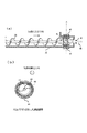
図7は実施例2における現像装置の構成の説明図である。図8は実施例2のシール構造の説明図である。図9は磁石部材の構成の説明図である。実施例2では、現像容器内の攪拌スクリュー端部に配置された既存の逆搬送スクリューを利用して磁石部材を用いたシール構造を形成している。
<Example 2>
FIG. 7 is an explanatory diagram of the configuration of the developing device according to the second embodiment. FIG. 8 is an explanatory diagram of a seal structure according to the second embodiment. FIG. 9 is an explanatory diagram of the configuration of the magnet member. In Example 2, a seal structure using a magnet member is formed by using an existing reverse conveying screw arranged at the end of a stirring screw in the developing container.
図8に示すように、端部スクリュー羽根の一例である逆搬送スクリュー45は、攪拌スクリュー26の長手方向の端部に設けられ、攪拌スクリュー26の一方向の回転に伴って軸受け部41から遠ざかる方向に現像剤を搬送する。
As shown in FIG. 8, the
磁石部材46は、現像容器22に固定して逆搬送スクリュー45の外周の少なくとも下半分を囲むように配置されている。逆搬送スクリュー45は、攪拌スクリュー26の長手方向の少なくとも片側で磁石部材46の外側にはみ出して配置される。
The
現像容器22は、空間48Bを軸受け部41と磁石部材46の間に設けられている。空間48Bは、磁石部材43によって形成される現像剤の磁気ブラシと磁気ブラシに干渉して回転する逆搬送スクリュー45とによって現像容器内からの現像剤の流れ込みが阻止されている。
The developing
磁石部材46に対向する領域で回転軸40が強磁性体材料で形成され、逆搬送スクリュー45が非磁性材料で形成される場合、攪拌スクリュー26の回転負荷が軽減される。一方、磁石部材46に対向する領域で回転軸及び逆搬送スクリュー45がいずれも強磁性体材料で形成される場合、磁気ブラシによるシール性能が強化される。
When the
図7に示すように、現像装置4aの現像容器22の内部は、隔壁27によって現像室23と攪拌室24とに区画され、現像室23には現像スクリュー25、攪拌室24には攪拌スクリュー26がそれぞれ配置されている。現像スクリュー25と攪拌スクリュー26が逆方向に現像剤を搬送することで、現像室23と攪拌室24に隔壁27を介した現像剤の循環が形成される。
As shown in FIG. 7, the inside of the developing
攪拌スクリュー26の下流側には、攪拌スクリュー26と逆方向に現像剤を搬送して攪拌室24の末端部の現像剤の圧力を緩和する逆搬送スクリュー45が配置される。同様に、現像スクリュー25の下流側には、現像スクリュー25と逆方向に現像剤を搬送して現像室23の末端部の現像剤の圧力を緩和する逆搬送スクリュー45が配置される。現像剤搬送方向の最下流部では、現像スクリュー25も攪拌スクリュー26も、スクリュー羽根が逆方向に巻かれて現像剤の逆搬送部を形成している。逆搬送スクリュー45は、軸受け部41へ向かう現像剤を押し返して、軸受け部41へ現像剤が侵入することを抑制する。
On the downstream side of the agitating
しかし、逆搬送スクリュー45の外周を現像容器22の内壁に接触させると、回転負荷の増大、現像剤の劣化促進が懸念される。このため、逆搬送スクリュー45と現像容器22の間には一定の間隙を設けている。
However, when the outer periphery of the
したがって、逆搬送スクリュー45によって軸受け部41への現像剤の侵入は抑制されるが、逆搬送スクリュー45の外周と現像容器22の隙間を通じて少しずつ軸受け部41へ現像剤が漏れ出していた。その結果、長期間使用する中では、軸受け部41に対する現像剤の漏れ出しが問題になる場合があった。
Therefore, although the
図8の(a)に示すように、実施例2では、逆搬送スクリュー45に対向する位置に磁石部材46を配置して、軸受け部41に対する現像剤の漏れ出しを阻止している。磁石部材46は、逆搬送スクリュー45と現像容器22の間に磁界を発生させて、両者の隙間を埋めるように磁気ブラシを形成して、逆搬送スクリュー45と現像容器22の間のシールを達成する。磁石部材46を配置することで現像容器22の内側面に形成される磁気ブラシの長さが、逆搬送スクリュー羽根45と現像容器22内壁間の間隙よりも長ければ、十分なシール効果が得られる。
As shown in FIG. 8A, in the second embodiment, a
図8の(b)に示すように、フレキシブルなシート状のマグネットシートを必要な寸法に切り出してU字型に折り曲げて磁石部材46とし、これを現像容器22の外側面に両面テープで貼付した。現像容器22中の現像剤は、重力方向下方に溜まっているので、磁石部材46を少なくとも現像容器22の重力方向下方で現像容器22内の現像剤面よりも高い位置まで磁気ブラシを形成させることが望ましい。逆搬送スクリュー45の現像容器22の重力方向下方で逆搬送スクリュー45を半周包囲するように磁石部材46を配置した。
As shown in FIG. 8B, a flexible sheet-like magnet sheet is cut out to a required size, bent into a U-shape to form a
逆搬送スクリュー45に対向して磁石部材46を配置していれば、ある程度のシール効果を得ることができる。しかし、実施例1で説明したように、逆搬送スクリュー45が磁石部材46よりも軸受け部41側、あるいは現像容器22の内側方向へはみ出るように配置されているとシール効果が高まる。
If the
以上を検討して次のように寸法を決定した。逆搬送スクリュー45は、軸径4mmの回転軸40に外径20mmの螺旋羽根を形成しており、現像容器22の内壁は、逆搬送スクリュー45の稜線に対して1mmの間隙をもって配置される。現像容器22の外壁には、厚さ2mmのフェライトマグネットシートを湾曲させた磁石部材46を、逆搬送スクリュー45の領域に貼付している。
Considering the above, the dimensions were determined as follows. The
磁石部材46は、逆搬送スクリュー45の軸受け部41側が2mmはみ出るようにした。現像容器22の内側方向に関しても逆搬送スクリュー45が磁石部材46からはみ出るように寸法を調整した。はみ出す距離は、少なくとも攪拌スクリュー26のガタツキ幅以上とした。
The
実施例2の構成においても、攪拌スクリュー26の搬送圧力によって現像剤が磁石部材46の領域に恒常的に少しずつ侵入してくる。そして、磁石部材46が拘束できる現像剤量に限界があるため、磁石部材46が拘束しきれなくなった現像剤の一部が徐々に軸受け部41側に漏れ出す可能性がある。しかし、磁石部材46の領域へ現像剤が恒常的に少しずつ侵入しても、逆搬送スクリュー45が回転して現像剤を現像容器22内へ恒常的に押し戻すため、軸受け部41側に現像剤が漏れ出すことはほとんどない。
Also in the configuration of the second embodiment, the developer constantly enters the region of the
図7に示すように、攪拌スクリュー26の上流側端部には逆搬送スクリュー45が配置されない。上流側端部では、攪拌スクリュー26が現像剤を軸受け部41から遠ざけるように搬送するため、攪拌スクリュー26のスクリュー羽根の一部に対応させて磁石部材56を配置すればよい。軸受け部41近傍の現像容器22の外側面に磁石部材46を貼付することで、攪拌スクリュー26の下流側端部と同様のシール効果が得られる。
As shown in FIG. 7, the
ただし、軸受け部41の内側位置に攪拌スクリュー26よりもピッチの短いシール専用の順搬送スクリューを設け、順搬送スクリューに対応する位置に磁石部材56を配置しても構わない。
However, a forward-conveying screw dedicated to the seal having a shorter pitch than the stirring
現像室23に配置される現像スクリュー25の両端部についても、攪拌スクリュー26の両端部と同様にシール構造が設けられている。下流側端部には逆搬送スクリューが配置され、上流側端部では現像スクリュー25の一部をシール構造に割り当てる。それぞれの領域に対応させて、現像容器の外周に磁石部材を配置して、攪拌室24と同様にシール構造を構成している。
As with both end portions of the agitating
<磁石部材>
図9の(a)に示すように、磁石部材46は、樹脂やゴム等をベースにしてフェライトを分散させた樹脂マグネットのマグネットシートである。シート面内にN極列とS極列がほぼ平行に交互に現れた磁極配列を有するマグネットシートを使用した。シート面内にN極列とS極列を交互に配置した場合は、N極列とS極列の間で磁力線が形成されるので、逆搬送スクリュー45の全周(又は半周)に磁気ブラシを均等に形成するために必要な磁力の確保が容易である。
<Magnet member>
As shown in FIG. 9A, the
これに対して、マグネットシートの表面・裏面にN極面、S極面を配置すると、磁力線がマグネットシートの端部にのみに集中して形成されてしまう。このため、逆搬送スクリュー45の全周(又は半周)の全域で均等に磁気ブラシを形成するための磁力を確保するのが難しい。
On the other hand, when the N pole surface and the S pole surface are arranged on the front and back surfaces of the magnet sheet, the magnetic lines of force are concentrated only on the end portion of the magnet sheet. For this reason, it is difficult to ensure the magnetic force for uniformly forming the magnetic brush throughout the entire circumference (or half circumference) of the
図9の(b)に示すように、磁石部材46は、マグネットシートのN極列およびS極列が回転軸40に対して略垂直になるように配置した。磁気ブラシは磁力線に沿って形成されるので、磁力線の始点と終点となるN極列とS極列に沿って、逆搬送スクリュー45の軸垂直断面を囲むように磁気ブラシが均等に形成される。N極列とS極列を回転軸40に対して概ね垂直に配置していれば、逆搬送スクリュー45と現像容器22の間隙を現像剤が通過する際、必ず磁気ブラシが密な部分を通過する。このため、より長時間の使用にも耐え得る。
As shown in FIG. 9B, the
これに対して、磁力線の始点と終点となるN極列とS極列が回転軸40と平行に配置されると、N極列とS極列の間の磁気ブラシが疎な部分が、逆搬送スクリュー45の軸垂直断面の一部に形成されてしまう。このため、長時間使用する中ではシール性に問題が生じかねない。
On the other hand, when the N pole row and the S pole row that are the starting and ending points of the magnetic field lines are arranged in parallel with the
<実施例3>
図10は実施例3における現像装置の構成の説明図である。図11は実施例3のシール構造の説明図である。図12は磁石部材の別の配置例の説明図である。実施例3では、現像容器の形状に合わせて磁石部材を逆搬送スクリューの全周に配置している。
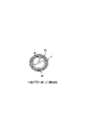
<Example 3>
FIG. 10 is an explanatory diagram of the configuration of the developing device according to the third embodiment. FIG. 11 is an explanatory diagram of a seal structure according to the third embodiment. FIG. 12 is an explanatory diagram of another arrangement example of the magnet members. In the third embodiment, the magnet member is arranged on the entire circumference of the reverse conveying screw in accordance with the shape of the developing container.
図10に示すように、現像装置4aは、逆搬送スクリュー45が現像容器22の円筒状に突出した部分に配置されている。図8の(b)に示すように、逆搬送スクリュー45の重力方向下方さえ磁石部材46が対向していれば、十分なシール効果は得られる。しかし、現像容器22内の現像剤面は温度湿度や運転状態(回転速度)に応じて変化するため、図5に示すように、逆搬送スクリュー(45)の全周に配置することが望ましい。
As shown in FIG. 10, in the developing
図11の(a)、(b)に示すように、そこで、実施例3では、磁石部材46を円筒状にして、逆搬送スクリュー45を全方向包囲するように配置した。逆搬送スクリュー45の周方向の全域において磁気ブラシを形成させることで、飛散したトナー等も含めて、より高いシール効果を得ている。
Thus, as shown in FIGS. 11A and 11B, in Example 3, the
図9の(b)に示すように、磁石部材46は、N極とS極が回転軸40に沿って交互に配置されている。磁気ブラシはN極とS極の間を連絡して内側に盛り上がるように形成されるので、逆搬送スクリュー45の軸垂直断面を囲むように磁気ブラシが均等に形成される。
As shown in (b) of FIG. 9, the
実施例3では、磁石部材46を現像容器22の外側に貼付した。現像容器22の外側に取り付けるのは、内側に取り付けるよりも作業が容易であり、製造の生産性が高くなるからである。
In Example 3, the
しかし、図12に示すように、磁石部材46は、現像容器22の内側面に固定して設けてもよい。現像容器22の内側に磁石部材46を貼付したほうが、磁石部材46の表面で現像剤を直接拘束できる分、現像剤の拘束力が高くなり、穂先の長い磁気ブラシを形成してシール性を高めることができる。
However, as shown in FIG. 12, the
したがって、磁石部材46を現像容器22の外側に配置するか内側に配置するかは、現像装置4aに求められるシール性能と磁石部材46の性能とに応じて、適宜選択すればよい。
Accordingly, whether the
実施例2、3では、逆搬送スクリュー45の回転軸40を強磁性体で形成した。実施例1で説明したように、回転軸40を強磁性体で構成すれば、磁石部材46と回転軸40の間に磁力線が集中するので、磁気ブラシが密に形成されて、シール性が高まるからである。
In Examples 2 and 3, the rotating
実施例2、3では、逆搬送スクリュー45のスクリュー羽根は非磁性体の樹脂材料で形成した。逆搬送スクリュー45のスクリュー羽根を強磁性体で形成すると、磁気ブラシが近接した逆搬送スクリュー45と磁石部材46との間を直接連絡するため、攪拌スクリュー26の回転負荷が大きくなるからである。
In Examples 2 and 3, the screw blades of the
しかし、実施例2、3においても、実施例1で説明したように、逆搬送スクリュー45を強磁性体金属で構成すれば、逆搬送スクリュー45と磁石部材46の間に磁力線が集中するので、磁気ブラシによるシール性能をより高めることがきる。
However, in Examples 2 and 3, as described in Example 1, if the
逆搬送スクリュー45のスクリュー羽根を強磁性体化する方法としては、この他、逆搬送スクリュー45を強磁性体粉金属粉入り樹脂材料で形成する方法がある。また、樹脂で形成した逆搬送スクリュー45のスクリュー羽根に強磁性体材料を貼り付けたり、吹き付け塗装したりする方法がある。
As another method of making the screw blades of the
<実施例4>
図13は実施例4のシール構造の説明図である。実施例4では、図10に示す現像装置4aにおいて、実施例3のシール構造と実施例1のシール構造とを組み合わせて一段のシール性能強化を図っている。
<Example 4>
FIG. 13 is an explanatory diagram of a seal structure according to the fourth embodiment. In the fourth embodiment, in the developing
図13に示すように、攪拌スクリュー26の下流側端部の逆搬送スクリュー45の周囲には、図11を参照して説明したように、磁石部材46による現像剤の磁気ブラシを利用したシール構造が配置される。そして、攪拌スクリュー26の軸受け部41には、図5を参照して説明したように、磁石部材43による現像剤の磁気ブラシにスクリュー羽根44を干渉させるシール構造が配置される。
As shown in FIG. 13, around the
すなわち、実施例3のシール構造と実施例1のシール構造とを直列に配置した構成ならば、より効果的に軸受け部41へのシール機能を達成でき、長時間の使用により耐え得る構成となる。
That is, if the seal structure of the third embodiment and the seal structure of the first embodiment are arranged in series, the seal function to the bearing
<実施例5>
図14は実施例5のシール構造の説明図である。図15は磁石部材の構成の説明図である。図16は別の磁石部材の構成の説明図である。実施例5では、図7に示す現像装置4aにおいて、攪拌スクリューの下流側端部の逆搬送スクリューのスクリュー羽根に磁石部材を配置してシールのための磁気ブラシを形成している。図15に示すように、逆搬送スクリュー45は、スクリュー羽根の稜線部に強磁性体材料が配置される。
<Example 5>
FIG. 14 is an explanatory diagram of a seal structure according to the fifth embodiment. FIG. 15 is an explanatory diagram of the configuration of the magnet member. FIG. 16 is an explanatory diagram of a configuration of another magnet member. In the fifth embodiment, in the developing
図14の(a)に示すように、逆搬送スクリュー45の外周面に磁石部材47を配置すると、その部分に現像剤の磁気ブラシmが形成される。磁気ブラシmは、現像容器22と逆搬送スクリュー45の隙間をシールして、この隙間を通じた軸受け部41側への現像剤の漏れ出しを阻止する。
As shown in FIG. 14A, when the
現像容器22中の現像剤は、重力方向下方に溜まっているので、逆搬送スクリュー45と現像容器22の重力方向下方の隙間が磁気ブラシmによってシールされることが望ましい。そこで、図14の(b)に示すように、逆搬送スクリュー45の外周に配置した磁石部材47と現像容器22の内壁面とが逆搬送スクリュー45の重力方向下方側半分で対向している構成とした。
Since the developer in the developing
図15に示すように、実施例5の逆搬送スクリュー45は、樹脂成形部材からなり、磁石部材47を貼り付ける面を確保するために、逆搬送スクリュー45の稜線上(先端部)に断面凹形状の凹溝45mが形成されている。
As shown in FIG. 15, the
逆搬送スクリュー45の稜線上に凹溝45mを設けて、帯状で弾性を有する磁石部材47を凹溝45mに半分埋め込んで接着剤で固定することにより取り付けてある。凹溝45mを設けることで、磁石部材47の位置決めが容易になって狭い稜線上でも貼り付け易くなり、且つ、接着剤が逆搬送スクリュー45の搬送傾斜面45aに流れ出るのを防止できる。
A
これに対して、逆搬送スクリュー45の先端部を平坦にして磁石部材47を貼り付ける際に接着剤の漏れ出しが発生すると、攪拌スクリュー26の搬送精度に影響を及ぼす可能性がある。また、見かけの悪さから、部品としての攪拌スクリュー26の受け入れ品質管理に影響を及ぼす可能性がある。
On the other hand, when the adhesive member leaks when the tip of the
実施例5における磁石部材47は、表面がN極面、裏面(凹溝45m内)がS極面の磁極配置のマグネットシートを線状にカットして使用した。マグネットシートのN極面とS極面は、逆でも構わない。このような構成を採用することで、磁石部材47の外周面に盛り上がるように磁気ブラシが形成されるため、逆搬送スクリュー45の稜線に沿って途切れのない現像剤の磁気ブラシが形成される。これにより、現像剤の磁気ブラシによるシール性能を高めることが可能である。
For the
なお、図16に示すように、S極とN極が交互に配置されたマグネットシートを線状にカットして用いてもよい。この場合も、攪拌スクリュー26の外周面と現像容器22の内壁面との間を十分に埋め合わせ得る磁気ブラシを形成可能である。また、S極とN極が交互に配置されたマグネットシートは、安価に製造可能であるため、コストの面で都合が良い。
In addition, as shown in FIG. 16, you may cut and use the magnetic sheet in which the south pole and the north pole are arrange | positioned alternately. Also in this case, it is possible to form a magnetic brush that can sufficiently fill the space between the outer peripheral surface of the stirring
<実施例6>
図17は実施例6のシール構造の説明図である。実施例6では、図10に示す現像装置4aにおいて、攪拌スクリューの下流側端部の逆搬送スクリューのスクリュー羽根に磁石部材を配置してシールのための磁気ブラシを形成している。
<Example 6>
FIG. 17 is an explanatory diagram of a seal structure according to the sixth embodiment. In the sixth embodiment, in the developing
図17の(a)、(b)に示すように、端部スクリュー羽根の一例である逆搬送スクリュー45は、スクリュー羽根の稜線部に沿って現像容器22の内周面に対向する磁石部材47を固定されている。磁石部材47によって逆搬送スクリュー45の稜線部に形成される現像剤の磁気ブラシが現像スリーブ28の回転に伴って現像容器22の内周面を摺擦する。これと並行して逆搬送スクリューが現像剤を搬送して、現像容器内から軸受け部41へ向かう現像剤の流れ込みを抑制する。
As shown in FIGS. 17A and 17B, the
磁石部材47を稜線上に取り付けた逆搬送スクリュー45に対応する現像容器22の部分が円筒状に形成されている場合、磁石部材47に形成される磁気ブラシが円筒状の内周面を連続的にシールする。これにより、逆搬送スクリュー45を全方向包囲するように周方向の全域において磁気ブラシmが隙間を塞ぐので、飛散したトナー等も含めてより高いシール性能を発揮する。
When the part of the developing
1a、1b、1c、1d 感光ドラム
3a、3b、3c、3d 露光装置
4a、4b、4c、4d 現像装置
22 現像容器、23 現像室、24 攪拌室
25 現像スクリュー、26 攪拌スクリュー
28 現像スリーブ、29 マグネットローラ
40 回転軸、41 軸受け部、42 ボールベアリング
43、46、47 磁石部材、44 スクリュー羽根
45 逆搬送スクリュー、48A、48B 空間
1a, 1b, 1c, 1d Photosensitive
Claims (2)
前記現像容器に形成された循環経路内の現像剤を循環搬送させるための搬送部材と、
前記搬送部材を回転可能に支持する軸受け部と、
前記軸受け部より循環経路側において、前記循環経路外から前記循環経路内に向けて現像剤を搬送するための搬送部と、
前記搬送部と前記現像容器との間隙に磁界を形成することで現像剤の磁気ブラシを形成する磁石部材と、を備えることを特徴とする現像装置。 A developer container containing a developer containing magnetic particles;
A transport member for circulating and transporting the developer in the circulation path formed in the developer container;
A bearing that rotatably supports the transport member;
A transport unit for transporting the developer from the outside of the circulation path toward the inside of the circulation path on the circulation path side from the bearing;
A developing device comprising: a magnetic member that forms a magnetic brush of developer by forming a magnetic field in a gap between the transport unit and the developing container.
Priority Applications (1)
| Application Number | Priority Date | Filing Date | Title |
|---|---|---|---|
| JP2011015149A JP5769431B2 (en) | 2011-01-27 | 2011-01-27 | Development device |
Applications Claiming Priority (1)
| Application Number | Priority Date | Filing Date | Title |
|---|---|---|---|
| JP2011015149A JP5769431B2 (en) | 2011-01-27 | 2011-01-27 | Development device |
Publications (2)
| Publication Number | Publication Date |
|---|---|
| JP2012155187A true JP2012155187A (en) | 2012-08-16 |
| JP5769431B2 JP5769431B2 (en) | 2015-08-26 |
Family
ID=46836954
Family Applications (1)
| Application Number | Title | Priority Date | Filing Date |
|---|---|---|---|
| JP2011015149A Expired - Fee Related JP5769431B2 (en) | 2011-01-27 | 2011-01-27 | Development device |
Country Status (1)
| Country | Link |
|---|---|
| JP (1) | JP5769431B2 (en) |
Cited By (4)
| Publication number | Priority date | Publication date | Assignee | Title |
|---|---|---|---|---|
| JP2014044321A (en) * | 2012-08-27 | 2014-03-13 | Ricoh Co Ltd | Developing device, process cartridge, and image forming apparatus |
| JP2014092664A (en) * | 2012-11-02 | 2014-05-19 | Fuji Xerox Co Ltd | Developer storage container, developing device, and image forming apparatus |
| JP2014102325A (en) * | 2012-11-19 | 2014-06-05 | Ricoh Co Ltd | Developing apparatus, process cartridge, and image forming apparatus |
| JP2015018055A (en) * | 2013-07-10 | 2015-01-29 | キヤノン株式会社 | Development device |
Citations (2)
| Publication number | Priority date | Publication date | Assignee | Title |
|---|---|---|---|---|
| JPH03282489A (en) * | 1990-03-30 | 1991-12-12 | Canon Inc | Developing device |
| JPH11167256A (en) * | 1997-12-02 | 1999-06-22 | Ricoh Co Ltd | Image forming device |
-
2011
- 2011-01-27 JP JP2011015149A patent/JP5769431B2/en not_active Expired - Fee Related
Patent Citations (2)
| Publication number | Priority date | Publication date | Assignee | Title |
|---|---|---|---|---|
| JPH03282489A (en) * | 1990-03-30 | 1991-12-12 | Canon Inc | Developing device |
| JPH11167256A (en) * | 1997-12-02 | 1999-06-22 | Ricoh Co Ltd | Image forming device |
Cited By (4)
| Publication number | Priority date | Publication date | Assignee | Title |
|---|---|---|---|---|
| JP2014044321A (en) * | 2012-08-27 | 2014-03-13 | Ricoh Co Ltd | Developing device, process cartridge, and image forming apparatus |
| JP2014092664A (en) * | 2012-11-02 | 2014-05-19 | Fuji Xerox Co Ltd | Developer storage container, developing device, and image forming apparatus |
| JP2014102325A (en) * | 2012-11-19 | 2014-06-05 | Ricoh Co Ltd | Developing apparatus, process cartridge, and image forming apparatus |
| JP2015018055A (en) * | 2013-07-10 | 2015-01-29 | キヤノン株式会社 | Development device |
Also Published As
| Publication number | Publication date |
|---|---|
| JP5769431B2 (en) | 2015-08-26 |
Similar Documents
| Publication | Publication Date | Title |
|---|---|---|
| US7412194B2 (en) | Developing apparatus | |
| JP2892456B2 (en) | Developing device | |
| US5287148A (en) | Magnetic seal for a developing apparatus | |
| CN100492210C (en) | Developing apparatus | |
| US7853186B2 (en) | Developing apparatus featuring multiple magnetic rollers | |
| JP3914755B2 (en) | Developing device and image forming apparatus | |
| US8811854B2 (en) | Developing apparatus having a magnetic seal | |
| JP5950567B2 (en) | Development device | |
| JP5769431B2 (en) | Development device | |
| JP5222802B2 (en) | Developing device and image forming apparatus including the same | |
| JP2012123199A (en) | Developing device | |
| JP2015087721A (en) | Development device | |
| JP2011232536A (en) | Development apparatus | |
| JP4698069B2 (en) | Developing device, magnet roller, image forming method, image forming apparatus, process cartridge | |
| JP2009265113A (en) | Developing device and image forming apparatus | |
| JP5750378B2 (en) | Developing device and image forming apparatus including the same | |
| JP2010276899A (en) | Developing device and image forming apparatus including the same | |
| JP4440004B2 (en) | Development device | |
| JP4673705B2 (en) | Developing apparatus and electrostatic recording apparatus | |
| JP2024152198A (en) | Developing device | |
| JPH0384572A (en) | electrophotographic equipment | |
| JP2006308732A (en) | Development device | |
| JP5509157B2 (en) | Developing device and image forming apparatus including the same | |
| JP2004246251A (en) | Developing device, image forming device and process cartridge | |
| JP5893293B2 (en) | Development device |
Legal Events
| Date | Code | Title | Description |
|---|---|---|---|
| RD04 | Notification of resignation of power of attorney |
Free format text: JAPANESE INTERMEDIATE CODE: A7424 Effective date: 20130228 |
|
| A621 | Written request for application examination |
Free format text: JAPANESE INTERMEDIATE CODE: A621 Effective date: 20140116 |
|
| A131 | Notification of reasons for refusal |
Free format text: JAPANESE INTERMEDIATE CODE: A131 Effective date: 20141028 |
|
| A977 | Report on retrieval |
Free format text: JAPANESE INTERMEDIATE CODE: A971007 Effective date: 20141029 |
|
| A521 | Request for written amendment filed |
Free format text: JAPANESE INTERMEDIATE CODE: A523 Effective date: 20141225 |
|
| TRDD | Decision of grant or rejection written | ||
| A01 | Written decision to grant a patent or to grant a registration (utility model) |
Free format text: JAPANESE INTERMEDIATE CODE: A01 Effective date: 20150526 |
|
| A61 | First payment of annual fees (during grant procedure) |
Free format text: JAPANESE INTERMEDIATE CODE: A61 Effective date: 20150623 |
|
| R151 | Written notification of patent or utility model registration |
Ref document number: 5769431 Country of ref document: JP Free format text: JAPANESE INTERMEDIATE CODE: R151 |
|
| LAPS | Cancellation because of no payment of annual fees |