JP2012155651A - Signal processing device and method, and program - Google Patents
Signal processing device and method, and program Download PDFInfo
- Publication number
- JP2012155651A JP2012155651A JP2011016398A JP2011016398A JP2012155651A JP 2012155651 A JP2012155651 A JP 2012155651A JP 2011016398 A JP2011016398 A JP 2011016398A JP 2011016398 A JP2011016398 A JP 2011016398A JP 2012155651 A JP2012155651 A JP 2012155651A
- Authority
- JP
- Japan
- Prior art keywords
- unit
- covered
- control
- sound
- acoustic signal
- Prior art date
- Legal status (The legal status is an assumption and is not a legal conclusion. Google has not performed a legal analysis and makes no representation as to the accuracy of the status listed.)
- Pending
Links
Images









Classifications
-
- G—PHYSICS
- G10—MUSICAL INSTRUMENTS; ACOUSTICS
- G10L—SPEECH ANALYSIS TECHNIQUES OR SPEECH SYNTHESIS; SPEECH RECOGNITION; SPEECH OR VOICE PROCESSING TECHNIQUES; SPEECH OR AUDIO CODING OR DECODING
- G10L25/00—Speech or voice analysis techniques not restricted to a single one of groups G10L15/00 - G10L21/00
- G10L25/48—Speech or voice analysis techniques not restricted to a single one of groups G10L15/00 - G10L21/00 specially adapted for particular use
- G10L25/51—Speech or voice analysis techniques not restricted to a single one of groups G10L15/00 - G10L21/00 specially adapted for particular use for comparison or discrimination
-
- G—PHYSICS
- G10—MUSICAL INSTRUMENTS; ACOUSTICS
- G10L—SPEECH ANALYSIS TECHNIQUES OR SPEECH SYNTHESIS; SPEECH RECOGNITION; SPEECH OR VOICE PROCESSING TECHNIQUES; SPEECH OR AUDIO CODING OR DECODING
- G10L25/00—Speech or voice analysis techniques not restricted to a single one of groups G10L15/00 - G10L21/00
- G10L25/03—Speech or voice analysis techniques not restricted to a single one of groups G10L15/00 - G10L21/00 characterised by the type of extracted parameters
Landscapes
- Engineering & Computer Science (AREA)
- Computational Linguistics (AREA)
- Signal Processing (AREA)
- Health & Medical Sciences (AREA)
- Audiology, Speech & Language Pathology (AREA)
- Human Computer Interaction (AREA)
- Physics & Mathematics (AREA)
- Acoustics & Sound (AREA)
- Multimedia (AREA)
- Telephone Function (AREA)
- Circuit For Audible Band Transducer (AREA)
- User Interface Of Digital Computer (AREA)
Abstract
【課題】発音不要かつ非接触な入力操作を実現することができるようにする。
【解決手段】覆われ検出部103は、時間周波数変換部102により音響信号が変換されて得られたパワースペクトルを解析し、そのパワースペクトルに観測される共振点の特徴(例えば周波数や大きさ等)から、音響信号入力部101が覆われている様子(覆われ状態)を判定し、その判定結果(覆われ状態を示す情報)を機器制御決定部104に供給する。機器制御決定部104は、覆われ検出部103から供給される判定結果(音響信号入力部101の覆われ状態を示す情報)に応じて、図示せぬ電子機器の制御内容を決定し、その制御情報(命令やデータ等)を、その電子機器等に出力する。本発明は、例えば、画像処理装置に適用することができる。
【選択図】図1A sound input-free and non-contact input operation can be realized.
A covering detection unit (103) analyzes a power spectrum obtained by converting an acoustic signal by a time-frequency conversion unit (102), and features of a resonance point observed in the power spectrum (for example, frequency, size, etc.) ) To determine whether the acoustic signal input unit 101 is covered (covered state), and supplies the determination result (information indicating the covered state) to the device control determining unit 104. The device control determination unit 104 determines the control content of an electronic device (not shown) according to the determination result (information indicating the cover state of the acoustic signal input unit 101) supplied from the cover detection unit 103, and the control Information (commands, data, etc.) is output to the electronic device. The present invention can be applied to, for example, an image processing apparatus.
[Selection] Figure 1
Description
本発明は、信号処理装置および方法、並びに、プログラムに関し、特に、発音不要かつ非接触な入力操作を実現することができるようにした信号処理装置および方法、並びに、プログラムに関する。 The present invention relates to a signal processing device and method, and a program, and more particularly, to a signal processing device and method, and a program that can realize a sound-free and non-contact input operation.
従来、デバイスに対する制御指示を入力する操作方法として、様々な操作方法が考えられている(例えば、特許文献参照)。 Conventionally, various operation methods are considered as an operation method for inputting a control instruction to a device (see, for example, Patent Literature).
特許文献には、イヤホンに設けられたマイクロホン若しくはその近傍を、ユーザが指等で叩くことにより、そのイヤホンが接続される携帯電話機等に対する制御指示を入力する方法が開示されている。 Patent Documents disclose a method of inputting a control instruction to a mobile phone or the like to which the earphone is connected when a user taps a microphone provided in the earphone or the vicinity thereof with a finger or the like.
しかしながら、近年、電子機器はより多様化しており、それに応じて、上述した特許文献に記載の方法以外の操作方法も求められている。 However, in recent years, electronic devices have become more diversified, and accordingly, operation methods other than those described in the above-mentioned patent documents are also required.
本発明は、このような状況に鑑みてなされたものであり、特許文献に記載の方法以外のデバイス操作方法として、発音不要かつ非接触な入力操作を実現することができるようにすることを目的とする。 The present invention has been made in view of such a situation, and an object of the present invention is to realize a non-pronunciation-free and non-contact input operation as a device operation method other than the method described in the patent document. And
本発明の一側面は、集音する集音手段と、前記集音手段により集音されて得られた音響信号の周波数特性における共振周波数および前記共振周波数の成分の大きさに基づいて、前記集音手段の覆われ状態を検出する覆われ検出手段と、前記覆われ検出手段により検出された前記集音手段の覆われ状態に応じて、制御対象の機器の制御内容を決定する機器制御決定手段とを備える信号処理装置である。 One aspect of the present invention is based on the sound collecting means for collecting sound, the resonance frequency in the frequency characteristic of the acoustic signal obtained by collecting the sound by the sound collecting means, and the magnitude of the component of the resonance frequency. Cover detection means for detecting the cover state of the sound means, and device control determination means for determining the control content of the device to be controlled according to the cover state of the sound collecting means detected by the cover detection means Is a signal processing device.
前記覆われ検出手段は、前記集音手段が覆われているか否か、若しくは、前記集音手段が覆われている度合いを検出することができる。 The covering detection means can detect whether or not the sound collecting means is covered, or the degree to which the sound collecting means is covered.
前記覆われ検出手段は、共振周波数および前記共振周波数の成分の大きさを所定の閾値と比較し、その比較結果に応じて前記集音手段の覆われ状態を検出することができる。 The covering detection means can compare the resonance frequency and the magnitude of the component of the resonance frequency with a predetermined threshold, and detect the covering state of the sound collecting means according to the comparison result.
前記覆われ検出手段は、複数の時刻における前記音響信号の周波数特性における共振周波数および前記共振周波数の成分の大きさを加算し、その加算結果に基づいて、前記集音手段の覆われ状態を検出することができる。 The covering detection means adds the resonance frequency and the magnitude of the component of the resonance frequency in the frequency characteristics of the acoustic signal at a plurality of times, and detects the covering state of the sound collecting means based on the addition result can do.
前記機器制御決定手段は、前記集音手段が覆われているか否か、若しくは、前記集音手段が覆われている度合いに応じて前記制御内容を決定することができる。 The device control determining means can determine the control content according to whether or not the sound collecting means is covered or the degree to which the sound collecting means is covered.
前記機器制御決定手段は、前記集音手段が覆われている時間に応じて前記制御内容を決定することができる。 The device control determining means can determine the control content according to the time during which the sound collecting means is covered.
前記機器制御決定手段は、前記集音手段が覆われている度合いに応じて、前記制御内容の制御量を決定することができる。 The device control determining means can determine the control amount of the control content according to the degree to which the sound collecting means is covered.
前記集音手段を複数備えることができる。 A plurality of the sound collecting means can be provided.
複数の前記集音手段のそれぞれにおいて得られた音響信号の周波数特性の差分を算出する差分算出手段をさらに備え、前記覆われ検出手段は、前記差分算出手段により算出された前記差分における前記共振周波数および前記共振周波数の成分の大きさに基づいて、前記集音手段の覆われ状態を検出することができる。 Difference calculating means for calculating a difference in frequency characteristics of the acoustic signal obtained in each of the plurality of sound collecting means is further provided, wherein the covering detection means is the resonance frequency in the difference calculated by the difference calculating means. And the covering state of the sound collecting means can be detected based on the magnitude of the component of the resonance frequency.
前記機器制御決定手段は、各集音手段の互いに同様の覆われ状態に対して、互いに異なる制御内容を割り当てることができる。 The device control determining means can assign different control contents to the same covered state of each sound collecting means.
前記集音手段は、通話処理のために集音し、前記覆われ検出手段は、前記集音手段により前記通話処理のために集音されて得られた音響信号の周波数特性における共振周波数および前記共振周波数の成分の大きさに基づいて、前記集音手段の覆われ状態を検出することができる。 The sound collecting means collects sound for call processing, and the covering detection means is a resonance frequency in a frequency characteristic of an acoustic signal obtained by collecting sound for the call processing by the sound collecting means, and the Based on the magnitude of the component of the resonance frequency, the covered state of the sound collecting means can be detected.
前記集音手段により集音されて得られた前記音響信号に対して音声認識処理を行う音声認識処理手段をさらに備え、前記機器制御決定手段は、前記覆われ検出手段により検出された前記集音手段の覆われ状態、および、前記音声認識処理手段による前記音声認識処理の結果に応じて、前記制御内容を決定することができる。 The apparatus further comprises voice recognition processing means for performing voice recognition processing on the acoustic signal obtained by collecting the sound by the sound collecting means, wherein the device control determining means is configured to detect the sound collection detected by the covered detection means. The control content can be determined in accordance with the state of the means covered and the result of the voice recognition processing by the voice recognition processing means.
本発明の一側面は、また、信号処理装置の信号処理方法であって、集音手段が、集音し、覆われ検出手段が、集音されて得られた音響信号の周波数特性における共振周波数および前記共振周波数の成分の大きさに基づいて、前記集音手段の覆われ状態を検出し、機器制御決定手段が、検出された前記集音手段の覆われ状態に応じて、制御対象の機器の制御内容を決定する信号処理方法である。 One aspect of the present invention is also a signal processing method of a signal processing device, in which a sound collecting unit collects sound and a covered detection unit collects sound, and a resonance frequency in a frequency characteristic of an acoustic signal obtained by collecting the sound. And the cover state of the sound collecting means is detected based on the magnitude of the component of the resonance frequency, and the device control deciding means controls the device to be controlled according to the detected cover state of the sound collecting means. This is a signal processing method for determining the control content.
本発明の一側面は、さらに、コンピュータを、集音する集音手段、前記集音手段により集音されて得られた音響信号の周波数特性における共振周波数および前記共振周波数の成分の大きさに基づいて、前記集音手段の覆われ状態を検出する覆われ検出手段、前記覆われ検出手段により検出された前記集音手段の覆われ状態に応じて、制御対象の機器の制御内容を決定する機器制御決定手段として機能させるためのプログラムである。 One aspect of the present invention is further based on a sound collecting means for collecting sound by a computer, a resonance frequency in a frequency characteristic of an acoustic signal obtained by collecting sound by the sound collecting means, and a magnitude of a component of the resonance frequency. A cover detecting unit for detecting a covering state of the sound collecting unit, and a device for determining control contents of the control target device according to the covering state of the sound collecting unit detected by the covering detecting unit. It is a program for functioning as control decision means.
本発明の一側面においては、集音されて得られた音響信号の周波数特性における共振周波数および共振周波数の成分の大きさに基づいて、集音手段の覆われ状態が検出され、検出された集音手段の覆われ状態に応じて、制御対象の機器の制御内容が決定される。 In one aspect of the present invention, the covered state of the sound collecting means is detected based on the resonance frequency and the magnitude of the component of the resonance frequency in the frequency characteristics of the acoustic signal obtained by collecting the sound. The control content of the device to be controlled is determined according to the covering state of the sound means.
本発明によれば、信号を処理することができる。特に、デバイス操作方法として、発音不要かつ非接触な入力操作を実現することができる。 According to the present invention, a signal can be processed. In particular, as a device operation method, it is possible to realize a non-contact input operation without sound generation.
以下、発明を実施するための形態(以下実施の形態とする)について説明する。なお、説明は以下の順序で行う。
1.第1の実施の形態(制御装置)
2.第2の実施の形態(制御装置)
3.第3の実施の形態(携帯型音楽再生装置)
4.第4の実施の形態(携帯電話機)
5.第5の実施の形態(パーソナルコンピュータ)
Hereinafter, modes for carrying out the invention (hereinafter referred to as embodiments) will be described. The description will be given in the following order.
1. First embodiment (control device)
2. Second embodiment (control device)
3. Third embodiment (portable music player)
4). Fourth embodiment (mobile phone)
5. Fifth embodiment (personal computer)
<1.第1の実施の形態>
[制御装置]
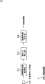
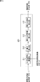
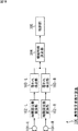
図1は、本発明を適用した制御装置の一実施の形態の構成を表している。
<1. First Embodiment>
[Control device]
FIG. 1 shows a configuration of an embodiment of a control device to which the present invention is applied.
図1に示される制御装置100は、電子機器(図示せず)を制御する装置であり、ユーザ等の指示に基づいて、制御対象の電子機器を制御する命令やデータ等の制御情報を出力する。 A control device 100 shown in FIG. 1 is a device that controls an electronic device (not shown), and outputs control information such as a command and data for controlling the electronic device to be controlled based on an instruction from a user or the like. .
図1に示されるように、制御装置100は、音響信号入力部101を有する。ユーザは、この音響信号入力部101周辺を例えば手等によって覆う等して、電子機器に対する指示を制御装置100に入力する。
As illustrated in FIG. 1, the control device 100 includes an acoustic
音響信号入力部101は、例えばマイクロホン等により構成されるセンサを有する。音響信号入力部101は、そのセンサにより周辺の音響信号を集音し、それを電気信号に変換する。
The acoustic
なお、音響信号は、例えば、所謂、物音や声等の音声、雑音、振動等、あらゆる物体や空間の振動に関する情報を含む。音響信号入力部101は、所定の範囲の周辺域に発生する音響信号(すなわち、あらゆる物体や空間の振動)を検出する。
Note that the acoustic signal includes, for example, information related to vibrations of all objects and spaces such as so-called sounds such as sounds and voices, noises, and vibrations. The acoustic
詳細については後述するが、ユーザが例えば手等を使って音響信号入力部101近傍を覆うと、その手(覆った物)と音響信号入力部101との間に、小空間が形成され、その小空間の存在(位置、形状、大きさ、覆った物の材質、形状、角度等)により、音響信号入力部101の伝達関数が変化し、集音された音響信号に共振点が観測されるようになる。
Although details will be described later, when the user covers the vicinity of the acoustic
制御装置100は、その電気信号の周波数成分を解析することにより、音響信号入力部101の伝達関数の変化(共振点の発生)を検出し、その伝達関数の変化からユーザが音響信号入力部101周辺を覆っている様子を検出し、音響信号入力部101の覆われ具合等に応じた制御情報を出力する。
The control device 100 detects a change in the transfer function (generation of a resonance point) of the acoustic
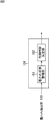
図1に示されるように、制御装置100は、音響信号入力部101の他に、時間周波数変換部102、覆われ検出部103、および機器制御決定部104を有する。時間周波数変換部102は、音響信号入力部101から出力される電気信号(音響信号入力部101が集音した音響信号(入力音)を変換した電気信号)を、例えばフーリエ変換等の任意の方法で周波数変換し、その周波数特性(パワースペクトル)を生成し、覆われ検出部103に供給する。
As illustrated in FIG. 1, the control device 100 includes a time
覆われ検出部103は、時間周波数変換部102により音響信号が変換されて得られたパワースペクトルを解析し、そのパワースペクトルに観測される共振点の特徴(例えば周波数や大きさ等)から、音響信号入力部101が覆われている様子(覆われ状態)を判定し、その判定結果(覆われ状態を示す情報)を機器制御決定部104に供給する。
The covering
機器制御決定部104は、覆われ検出部103から供給される判定結果(音響信号入力部101の覆われ状態を示す情報)に応じて、図示せぬ電子機器の制御内容を決定し、その制御情報(命令やデータ等)を、その電子機器等に出力する。
The device
このように、ユーザは、制御装置100に対して、発音することなく、かつ、制御装置100(音響信号入力部101等)に接触することなく、単に、音響信号入力部101周辺を覆うだけで、電子機器に対する指示を入力することができる。つまり、制御装置100は、発音不要かつ非接触な入力操作を実現することができる。
In this way, the user simply covers the periphery of the acoustic
[覆われ検出部]
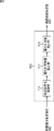
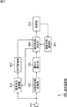
図2は、図1の覆われ検出部103の主な構成例を示すブロック図である。図2に示されるように、覆われ検出部103は、周波数特性蓄積部111、覆われ特徴量算出部112、および覆われ状態検出部113を有する。
[Cover detection part]
FIG. 2 is a block diagram illustrating a main configuration example of the covering
周波数特性蓄積部111は、例えば、ハードディスク、フラッシュメモリ、若しくはRAM(Random Access Memory)等の任意の記憶媒体を有し、時間周波数変換部102から供給された入力音の周波数特性(パワースペクトル)を記憶する。周波数特性蓄積部111は、所定のタイミング、若しくは、覆われ特徴量算出部112の要求に基づいて、記憶しているパワースペクトルを覆われ特徴量検出部112に供給する。
The frequency
覆われ特徴量算出部112は、周波数特性蓄積部111から取得したパワースペクトルを解析する。
The covered feature
ここで、覆われ状態と、その特徴について説明する。 Here, the covered state and its features will be described.
ユーザが例えば手等を使って音響信号入力部101近傍を覆うと、その手(覆った物)と音響信号入力部101との間に、小空間が形成される。この小空間は、完全に周囲と区切られた閉空間でなくてもよく、手等によって空間の一部が区切られたもの(周囲と区切られていない部分がある領域)であってもよい。
When the user covers the vicinity of the acoustic
この小空間の存在により、音響信号入力部101の伝達関数が変化し、入力音のパワースペクトルに共振点が観測されるようになる。
Due to the presence of this small space, the transfer function of the acoustic
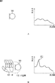
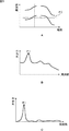
図3は、覆われ状態の検出の動作原理を説明する図である。例えば、図3Aの左側に示されるように、音響信号入力部101の周辺(集音範囲)が覆われていないとする。この状態の場合、音響信号入力部101からの入力音のパワースペクトルには、図3Aの右側に示されるグラフのように、共振点は検出されない。
FIG. 3 is a diagram for explaining the operation principle of detection of a covered state. For example, as shown on the left side of FIG. 3A, it is assumed that the periphery (sound collection range) of the acoustic
これに対して、例えば、図3Bの左側に示されるように、ユーザが、音響信号入力部101の周辺(集音範囲)を手131で覆うと、その手131と音響信号入力部101との間に小空間132が形成される。この状態の場合、図3Bの右側に示されるグラフのように、音響信号入力部101からの入力音のパワースペクトルにおいて所定の周波数のスペクトルが周囲に対して極端に大きくなる。つまり、スペクトルのピークP1が観測される。このピークP1が共振点である。以下において共振点P1とも称する。
On the other hand, for example, as shown on the left side of FIG. 3B, when the user covers the periphery (sound collection range) of the acoustic
図2に戻り、覆われ特徴量算出部112は、この共振点P1を特徴量化する。覆われ特徴量算出部112は、算出した特徴量を、覆われ状態検出部113に供給する。
Returning to FIG. 2, the covered feature
覆われ状態検出部113は、覆われ特徴量算出部112から供給された特徴量に基づいて、音響信号入力部101の覆われ状態を判定し、その判定結果を覆われ状態を示す情報(覆われ状態情報)として機器制御決定部104に供給する。
The covering
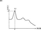
例えば、覆われ特徴量算出部112は、図4に示されるように、パワースペクトルに観測される共振点P1の周波数(共振周波数)Fと大きさGとを特徴量として算出する。
For example, as shown in FIG. 4, the covered feature
これに対して、覆われ状態検出部113は、例えば図5Aに示されるように、共振点P1の周波数Fが、閾値F thresh1と閾値F thresh2との間にあり、かつ、図5Bに示されるように、共振点P1のスペクトルの大きさGが閾値G thresh1と閾値G thresh2との間にある場合、音響信号入力部101が覆われていると判定する。また、覆われ状態検出部113は、例えば、大きさGの値によって、その覆われ具合を判定する。
On the other hand, as shown in FIG. 5A, for example, the covered
覆われ具合とは、ユーザの手等、音響信号入力部101を覆う物が、音響信号入力部101をどの程度覆っているかを示す。共振点P1のスペクトルの大きさGは、小空間の位置、形状、大きさ、覆った物の材質、位置、角度、形状等によって変化する。つまり、共振点P1の大きさGは、音響信号入力部101の覆われ方(覆われ具合)によって変化する。例えば、ユーザが手等で、音響信号入力部101のより近くでより広く覆う(よりしっかり覆う)と、共振点P1のスペクトルの大きさGは、大きくなる。そこで、覆われ状態検出部113は、例えば、大きさGの値が大きいほど、音響信号入力部101がしっかり覆われていることを示す値を出力する。
The covering condition indicates how much an object that covers the acoustic
例えば、覆われ状態検出部113は、大きさGが閾値G thresh2の場合、覆われ状態情報として値「0」を出力し、大きさGが閾値G thresh1に近づくに従って、より「1」に近い値を出力する。
For example, when the magnitude G is the threshold value G thresh2, the covered
なお、以上においては、共振点P1の周波数Fとスペクトルの大きさGが閾値判定されることにより覆われ具合が判定されるように説明したが、覆われ状態を検出する方法は、これ以外であっても良い。 In the above description, the frequency F of the resonance point P1 and the magnitude G of the spectrum have been described as being determined by threshold determination. However, the method for detecting the state of coverage is other than this. There may be.
例えば、スペクトルの代わりに、スペクトルの概形を表すパラメータ、例えば、線形予測係数やケプストラム、MFCC(Mel Frequency Cepstral Coefficient)等が用いられるようにしてもよい。 For example, instead of the spectrum, a parameter representing the outline of the spectrum, for example, a linear prediction coefficient, a cepstrum, MFCC (Mel Frequency Cepstral Coefficient), or the like may be used.
また、例えば、入力音のパワースペクトルのピーク(共振点P1)周辺の周波数成分のスペクトルの形状に基づいて覆われ具合が判定されるようにしてもよい。 Further, for example, the covering condition may be determined based on the shape of the spectrum of the frequency component around the power spectrum peak (resonance point P1) of the input sound.
例えば、覆われ特徴量算出部112が、入力音のパワースペクトルのピーク(共振点P1)周辺の周波数成分のスペクトルの形状を特徴量として算出し、覆われ状態検出部113が、その形状をモデルケースと比較することにより覆われ具合を判定するようにしてもよい。
For example, the covered feature
この場合、例えば、覆われ状態検出部113が、覆われ特徴量算出部112より供給される共振点P1を含む所定の周波数帯域のスペクトルと、音響信号入力部101が所定の覆われ具合で覆われた場合の同周波数帯域のスペクトル(モデルケースのスペクトル)とを比較し、その近似度によって、覆われ状態情報の値(例えば値「0」乃至「1」)を決定し、出力するようにしてもよい。
In this case, for example, the covering
このようにすることにより、覆われ状態の判定をより正確に行うことができる。なお、モデルケースの数は任意であり、その数が多いほど、覆われ状態の判定をより正確に行うことができる。 By doing in this way, the covering state can be determined more accurately. Note that the number of model cases is arbitrary, and the larger the number, the more accurately the covering state can be determined.
また、例えば、音響信号入力部101が覆われた状態のスペクトル、覆われていない状態のスペクトルをそれぞれ大量に集め、ニューラルネットワーク、サポートベクタマシン、GMM(Gaussian Mixture Models)といった統計的識別器を使用することも可能である。統計的識別法においても、しっかり覆っている状態のものを「1」、軽く覆われているものを「0.5」、覆われていないものを「−1」のように対応付けておくことで、判定結果は覆われている状態を反映する結果を得ることができる。
In addition, for example, a large amount of spectrum in which the acoustic
このようにすることにより、覆われ状態検出部113は、デバイスの個体特性や使用環境等の各種条件を、覆われ状態の判定に反映させることができ、より正確な判定を行うことができる。
By doing so, the covered
なお、以上のように、所定のサンプリング時刻のみのスペクトルを用いて覆われ特徴量の算出や覆われ状態の検出が行われる場合、周波数特性蓄積部111は省略することもできる。
As described above, the frequency
逆に、周波数特性蓄積部111は、複数のサンプリングタイミングのスペクトルを記憶するようにしてもよい。その場合、覆われ特徴量算出部112が、周波数特性蓄積部111に蓄積される複数の(サンプリングタイミングの)スペクトルを用いて、覆われ特徴量を算出するようにしてもよい。つまり、覆われ特徴量算出部112が、例えば図6Aに示されるようなスペクトログラムから、ピーク(共振点P1)に関する特徴量を算出するようにしてもよい。
Conversely, the frequency
図6Aに示されるスペクトログラムは、複数の時刻のスペクトルの集合である。例えば、図6Aの点線に示されるある時刻において、音響信号入力部101がユーザの手等で覆われていると、図6Bに示されるように、その時刻のスペクトルにおいてピークP1が観測される。
The spectrogram shown in FIG. 6A is a set of spectra at a plurality of times. For example, when the acoustic
この覆われ状態が変化しないとすると、その期間のスペクトログラムにおいては、図6Aに示されるように、ピークP1の連なりが、帯状(帯P2)となって表される。したがって、周波数特性蓄積部111に蓄積される周波数特性を時間方向に加算することで、図6Cに示されるように、周波数に変化が少ないものは大きく、周波数に変化があるものは小さく抑圧することができる。つまり、ピーク(共振点P1)のスペクトルの大きさを強調することができる。これにより、覆われ状態検出部113による覆われ状態の判定をより容易にすることができる。
Assuming that this covered state does not change, in the spectrogram for that period, as shown in FIG. 6A, a series of peaks P1 is represented as a band (band P2). Therefore, by adding the frequency characteristics accumulated in the frequency
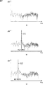
なお、一般的には、覆われ具合(被覆度)によってスペクトルの大きさGだけでなく、共振周波数Fが変化する。図7に覆われ具合(被覆度)の違いによる音響信号の周波数特性の差を示す。図7Aに示されるグラフは、音響信号入力部101が覆われていない状態(通常時)の周波数特性の例を示す。
In general, not only the magnitude G of the spectrum but also the resonance frequency F changes depending on the degree of coverage (coverage). FIG. 7 shows the difference in the frequency characteristics of the acoustic signal due to the difference in the degree of coverage (coverage). The graph shown in FIG. 7A shows an example of frequency characteristics in a state where the acoustic
これに対して、図7Bに示されるグラフは、音響信号入力部101が少し覆われている状態(被覆度が小さい場合)の周波数特性の例を示す。この場合、線151により示されるように、約2100Hzにピークが観測される。すなわち、共振周波数F=約2100Hzである。
On the other hand, the graph shown in FIG. 7B shows an example of the frequency characteristics when the acoustic
これに対して、図7Cに示されるグラフは、音響信号入力部101がしっかり覆われている状態(被覆度が大きい場合)の周波数特性の例を示す。この場合、線152により示されるように、約1060Hzにピークが観測される。すなわち、共振周波数F=約1060Hzである。
On the other hand, the graph shown in FIG. 7C shows an example of frequency characteristics in a state where the acoustic
このように、覆われ状態(被覆度)が変化することにより、共振点のスペクトルの大きさGだけでなく、共振周波数Fも変化するので、覆われ状態検出部113が、この共振周波数Fの変化を用いて、覆われ状態の判定を行うようにしてもよい。
As described above, since the cover state (coverage) changes, not only the spectrum size G of the resonance point but also the resonance frequency F changes. Therefore, the cover
[機器制御決定部]
図8は、図1の機器制御決定部104の主な構成例を示すブロック図である。図8に示されるように、機器制御決定部104は、覆われ状態蓄積部161と制御内容決定部162を有する。
[Equipment control decision unit]
FIG. 8 is a block diagram illustrating a main configuration example of the device
覆われ状態蓄積部161は、例えば、ハードディスク、フラッシュメモリ、若しくはRAM等の任意の記憶媒体を有し、覆われ検出部103から供給される覆われ状態情報(覆われ状態情報)を記憶する。覆われ状態蓄積部161は、所定のタイミング、若しくは、制御内容決定部162の要求に基づいて、記憶している覆われ状態情報を制御内容決定部162に供給する。
The covered
制御内容決定部162は、覆われ状態蓄積部161から覆われ状態情報を取得すると、その値等基づいて、ユーザ操作に対応する電子機器(図示せず)の制御内容を決定し、その制御情報(命令やデータ等)を出力する。
When the control
図9は、覆われ検出部103の出力(覆われ状態情報)の時間軸に沿った変化の例を示す図である。図9に示される曲線171は、覆われ状態情報の値を示している。
FIG. 9 is a diagram illustrating an example of a change along the time axis of the output (covered state information) of the
制御内容決定部162は、例えば、このような覆われ状態情報に対して、所定の閾値Vを設定し、その閾値Vを用いて音響信号入力部101が覆われているか否かを判定する。制御内容決定部162は、例えば、覆われ状態情報の値が閾値Vより大きい(若しくは閾値V以上である)場合、音響信号入力部101が覆われていると判定する。換言するに、制御内容決定部162は、例えば、覆われ状態情報の値が閾値V以下である(若しくは閾値Vより小さい)場合、音響信号入力部101が覆われていないと判定する。
For example, the control
そして、制御内容決定部162は、その判定結果に基づいて、制御内容を決定し、その制御情報を出力する。これにより、制御内容決定部162は、音響信号入力部101が覆われているか否かに応じた内容の制御情報を出力することができる。
And the control
なお、制御内容決定部162が、覆われ状態情報に対して閾値を複数設け、覆われているか否かだけでなく、その覆われ度合いを判定するようにしてもよい。例えば、図9の例において、覆われ状態情報の値Xが、閾値Vより大きい(X>V)場合、音響信号入力部101がしっかり覆われている(覆われ度合いが大きい)と判定され、V≧X>0の場合、音響信号入力部101が軽く覆われている(覆われ度合いが小さい)と判定され、0≧Xの場合、音響信号入力部101が覆われていないと判定されるようにしてもよい。
Note that the control
このようにすることにより、制御内容決定部162は、覆われ状態情報から、より多様な制御内容を決定することができる。
By doing in this way, the control
もちろん、制御内容決定部162が、さらに多くの閾値を設定し、さらに多くの状態に判別するようにしてもよい。また、制御内容決定部162が、覆われ状態情報の値Xそのもの、若しくは、覆われ状態情報の値Xから一意的に求められる値を、覆われ度合いとし、その覆われ度合いを含む制御情報を出力するようにしてもよい。
Of course, the control
これらの場合、例えば、制御内容決定部162は、覆われ状態情報の値Xを覆われ度合いとし、その覆われ度合いに応じた制御量で電子機器を制御する制御情報を生成し、出力するようにしてもよい。つまり、この制御情報が示す制御内容には、制御の種類(どのような制御を行うか)だけでなく、覆われ度合いに対応する制御量(どの程度制御するか)を示す情報も含まれる。
In these cases, for example, the control
このようにすることにより、制御内容決定部162は、覆われ状態情報から、さらに、より多様な制御内容を決定することができる。
By doing in this way, the control
さらに、制御内容決定部162が、覆われ状態情報の値Xの変化のパターン(覆われ状態若しくは覆われ度合いの履歴)に応じて制御内容を決定するようにしてもよい。
Furthermore, the control
なお、制御内容決定部162は、例えば、図10に示されるように、覆われ状態情報に基づいて求められる音響信号入力部101が覆われている時間(覆われ時間)の長さに基づいて制御内容を決定するようにしてもよい。
For example, as shown in FIG. 10, the control
図10に示される曲線171も、図9の場合と同様に、覆われ状態情報の値を示している。例えば、制御内容決定部162が、時間閾値Tを設定し、図10に示されるように、覆われている(覆われ検出部103の出力Xが、値「0」より大きい)区間が、この時間閾値Tより大きいか否かによって制御内容を決定するようにしてもよい。
A
例えば図10において、覆われている区間T2の長さは、時間閾値Tより長く、覆われている区間T1の長さは、時間閾値Tより短い。制御内容決定部162は、このような2つの覆われている区間T1およびT2に対して、互いに異なる制御内容を割り当てるようにすることもできる。
For example, in FIG. 10, the length of the covered section T2 is longer than the time threshold T, and the length of the covered section T1 is shorter than the time threshold T. The control
このようにすることにより、制御内容決定部162は、覆われている区間の長さに応じて、制御内容を決定することができる。
By doing in this way, the control
なお、制御内容決定部162が、時間閾値Tを複数設け、各閾値と覆われている区間の長さの関係に応じて制御内容を決定するようにしてもよい。このようにすることにより、制御内容決定部162は、覆われている区間の長さから、より多様な制御内容を決定することができる。もちろん、図9の場合と同様に、覆われている区間の長さを制御量とされるようにしてもよい。
Note that the control
さらに、制御内容決定部162が、覆われている区間の長さの変化のパターン(覆われている区間の長さの履歴)に応じて制御内容を決定するようにしてもよい。
Furthermore, the control
また、上述した複数の制御内容決定方法を組み合わせるようにしてもよい。さらに、上述した制御内容決定方法以外の方法を組み合わせるようにしてもよい。例えば、制御内容決定部162が、さらに、覆われている状態と判定される時の時刻や制御装置100の位置等に応じて制御内容を決定するようにしてもよい。
Moreover, you may make it combine the several control content determination method mentioned above. Furthermore, methods other than the control content determination method described above may be combined. For example, the control
このようにすることにより、制御内容決定部162は、より多様な制御内容を決定することができる。
By doing in this way, the control
[制御処理の流れ]
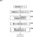
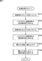
次に、図11のフローチャートを参照して、制御装置100により実行される制御処理の流れの例を説明する。
[Flow of control processing]
Next, an example of the flow of control processing executed by the control device 100 will be described with reference to the flowchart of FIG.
制御処理が開始されると、制御装置100の音響信号入力部101は、ステップS101において、音響信号の入力を受け付ける。ステップS102において、時間周波数変換部102は、ステップS101において入力された音響信号に対して、フーリエ変換等の時間・周波数変換を行い、音響信号(入力音)の周波数特性(パワースペクトル)を求める。
When the control process is started, the acoustic
ステップS103において、覆われ検出部103は、ステップS102において生成されたパワースペクトルを用いて、ユーザ操作等による音響信号入力部101の覆われ状態の検出を行う。ステップS104において、機器制御決定部104は、ステップS103において検出(判定)された覆われ状態に応じて、制御対象の電子機器に対する制御内容を決定し(ユーザが行った操作(ユーザ指示)に対応する制御内容を決定し)、その制御情報を出力する。
In step S103, the covering
ステップS104の処理を終了すると、制御装置100は、制御処理を終了する。制御装置100は、このような制御処理を繰り返し実行する。実際には、制御処理の各ステップの処理が適宜並列に実行される。例えば、ステップS101の処理が行われた後にステップS102の処理が実行されるのと並行して、次の制御処理が開始され、ステップS101の処理(次のサンプリングタイミングの音響信号の入力)が行われる。 When the process of step S104 ends, the control device 100 ends the control process. The control device 100 repeatedly executes such control processing. Actually, the process of each step of the control process is appropriately executed in parallel. For example, the next control process is started in parallel with the execution of the process of step S102 after the process of step S101 is performed, and the process of step S101 (input of an acoustic signal at the next sampling timing) is performed. Is called.
[覆われ状態検出処理の流れ]
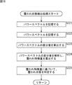
次に、図12のフローチャートを参照して、図11のステップS103において覆われ検出部103により実行される覆われ状態検出処理の流れの例を説明する。
[Flow of cover state detection process]
Next, an example of the flow of the covered state detection process executed by the covered
覆われ状態検出処理が開始されると、周波数特性蓄積部111は、ステップS121において、図11のステップS102において算出されたパワースペクトルを記憶する。ステップS122において、覆われ特徴量算出部112は、周波数特性蓄積部111が蓄積しているパワースペクトルを解析し、そのパワースペクトルの特徴を示す覆われ特徴量を算出する。例えば、ピーク(共振点)の周波数Fやスペクトルの大きさG等が覆われ特徴量として算出される。
When the cover state detection process is started, the frequency
なお、ステップS122において、覆われ特徴量算出部112が、1サンプリング分のパワースペクトルのみから覆われ特徴量を算出する場合、ステップS121の処理を省略し、図11のステップS102においてパワースペクトルが算出され次第、ステップS122の処理が実行されるようにしてもよい。また、ステップS122において、覆われ特徴量算出部112が、複数サンプリング分のパワースペクトルを用いて、覆われ特徴量を算出する場合、ステップS121の処理が所定回数(複数回)行われてから、ステップS122の処理が行われるようにしてもよい。
In step S122, when the covered feature
ステップS123において、覆われ状態検出部113は、ステップS122において算出された覆われ特徴量に基づいて、音響信号入力部101の覆われ状態(ユーザ操作の内容)を判定し、その覆われ状態を示す覆われ状態情報を機器制御決定部104に出力する。
In step S123, the covering
ステップS123の処理が終了すると、覆われ検出部103は、覆われ状態検出処理を終了し、処理を図11のステップS103に戻し、ステップS104以降の処理を実行させる。
When the process of step S123 ends, the
[制御内容決定処理の流れ]
次に、図13のフローチャートを参照して、図11のステップS104において、機器制御決定部104により実行される制御内容決定処理の流れの例を説明する。
[Flow of control content determination process]
Next, an example of the flow of control content determination processing executed by the device
制御内容決定処理が開始されると、覆われ状態蓄積部161は、ステップS141において、図12のステップS123において生成された覆われ状態情報を記憶する。ステップS142において、制御内容決定部162は、覆われ状態蓄積部161が蓄積している覆われ状態情報により示される音響信号入力部101の覆われ状態に基づいて、電子機器に対する制御内容を決定する。
When the control content determination process is started, the covered
なお、ステップS142において、制御内容決定部162が、1回分の覆われ状態情報のみから制御内容を決定する場合、ステップS141の処理を省略し、図12のステップS123において覆われ状態情報が生成され次第、ステップS142の処理が実行されるようにしてもよい。また、ステップS142において、制御内容決定部162が、複数回分の覆われ状態情報を用いて制御内容を決定する場合、ステップS141の処理が所定回数(複数回)行われてから、ステップS142の処理が行われるようにしてもよい。
In step S142, when the control
ステップS142の処理が終了すると、機器制御決定部104は、制御内容決定処理を終了し、処理を図11のステップS104に戻し、制御処理を終了させる。
When the process of step S142 ends, the device
以上のように、制御装置100が各処理を実行することにより、ユーザは、制御装置100に対して、発音することなく、かつ、制御装置100(音響信号入力部101等)に接触することなく、単に、音響信号入力部101の周辺を覆うだけで、電子機器に対する指示を入力することができるようになる。つまり、制御装置100は、発音不要かつ非接触な入力操作を実現することができる。
As described above, when the control device 100 executes each process, the user does not sound the control device 100 and does not touch the control device 100 (the acoustic
<2.第2の実施の形態>
[制御装置]
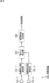
音響信号入力部101が複数設けられるようにしてもよい。図14は、本発明を適用した制御装置の一実施の形態の構成を表している。
<2. Second Embodiment>
[Control device]
A plurality of acoustic
図14に示される制御装置200は、図1の制御装置100と同様の装置であり、ユーザ等により行われる音響信号入力部を覆う動作を受け付け、そのユーザ指示により指定される制御内容の制御情報を生成し、制御対象の電子機器等にその制御情報を出力する。したがって、制御装置200は、基本的に制御装置100と同様の構成を有するが、制御装置100と異なり、音響信号入力部101を2つ有する(音響信号入力部101−1および音響信号入力部101−2)。 The control device 200 shown in FIG. 14 is the same device as the control device 100 of FIG. 1, receives an operation for covering an acoustic signal input unit performed by a user or the like, and controls information of control contents specified by the user instruction And output the control information to the electronic device to be controlled. Therefore, the control device 200 basically has the same configuration as the control device 100, but unlike the control device 100, has two acoustic signal input units 101 (an acoustic signal input unit 101-1 and an acoustic signal input unit 101). -2).
音響信号入力部101−1および音響信号入力部101−2は、それぞれ、制御装置100の音響信号入力部101と同様のセンサを有し、集音した音響信号を電気信号に変換する。音響信号入力部101−1および音響信号入力部101−2は、ユーザ等により覆われていない状態において、互いに略同じ音響信号を集音できる程度に互いの近傍に設置される。ただし、音響信号入力部101−1および音響信号入力部101−2は、ユーザ等が、それらのいずれか一方のみを覆うことができる程度に離されて設置される。
The acoustic signal input unit 101-1 and the acoustic signal input unit 101-2 each have a sensor similar to the acoustic
なお、以下において、音響信号入力部101−1および音響信号入力部101−2を互いに区別して説明する必要が無い場合、単に、それらを音響信号入力部101と称する場合もある。
In the following, when there is no need to distinguish between the acoustic signal input unit 101-1 and the acoustic signal input unit 101-2, they may be simply referred to as the acoustic
また、図14に示されるように、制御装置200は、時間周波数変換部102も2つ有する(時間周波数変換部102−1および時間周波数変換部102−2)。時間周波数変換部102−1は、音響信号入力部101−1から出力される電気信号(音響信号入力部101−1が集音した音響信号(入力音)を変換した電気信号)を、例えばフーリエ変換等の任意の方法で周波数変換し、その周波数特性(パワースペクトル)を生成する。時間周波数変換部102−2は、音響信号入力部101−2から出力される電気信号(音響信号入力部101−2が集音した音響信号(入力音)を変換した電気信号)を、例えばフーリエ変換等の任意の方法で周波数変換し、その周波数特性(パワースペクトル)を生成する。 Further, as shown in FIG. 14, the control device 200 also includes two time frequency conversion units 102 (a time frequency conversion unit 102-1 and a time frequency conversion unit 102-2). The time-frequency conversion unit 102-1 converts the electrical signal output from the acoustic signal input unit 101-1 (the electrical signal obtained by converting the acoustic signal (input sound) collected by the acoustic signal input unit 101-1), for example, Fourier Frequency conversion is performed by an arbitrary method such as conversion, and the frequency characteristic (power spectrum) is generated. The time-frequency conversion unit 102-2 converts an electrical signal output from the acoustic signal input unit 101-2 (an electrical signal obtained by converting an acoustic signal (input sound) collected by the acoustic signal input unit 101-2), for example, Fourier Frequency conversion is performed by an arbitrary method such as conversion, and the frequency characteristic (power spectrum) is generated.
制御装置200は、制御装置100が有する覆われ検出部103の代わりに、覆われ検出部203を有する。つまり、制御装置200は、音響信号入力部101−1および音響信号入力部101−2、時間周波数変換部102−1および時間周波数変換部102−2、覆われ検出部203、並びに、機器制御決定部104を有する。
The control device 200 includes a
覆われ検出部203は、基本的に制御装置100の覆われ検出部103と同様の処理部であるが、覆われ検出部103の場合と異なり、時間周波数変換部102−1および時間周波数変換部102−2の両方の出力(パワースペクトル)を取得する。覆われ検出部203は、その両入力(パワースペクトル)の差分を算出し、その差分値から覆われ特徴量を算出し、覆われ状態を判定し、覆われ状態情報を機器制御決定部104に出力する。
The
[覆われ検出部]
図15は、図14の覆われ検出部203の主な構成例を示すブロック図である。図15に示されるように、覆われ検出部203は、覆われ検出部103の場合の周波数特性蓄積部111の代わりに周波数特性蓄積部211を有し、さらに、覆われ特徴量算出部112および覆われ状態検出部113の他に差分算出部212を有する。
[Cover detection part]
FIG. 15 is a block diagram illustrating a main configuration example of the covering
周波数特性蓄積部211は、周波数特性蓄積部111と同様に、例えば、ハードディスク、フラッシュメモリ、若しくはRAM等の任意の記憶媒体を有し、時間周波数変換部102−1から供給された入力音の周波数特性(パワースペクトル)と、時間周波数変換部102−2から供給された入力音の周波数特性(パワースペクトル)との両方を記憶する。周波数特性蓄積部211は、所定のタイミング、若しくは、差分算出部212の要求に基づいて、記憶している両方のパワースペクトルを差分算出部212に供給する。
Similarly to the frequency
差分算出部212は、周波数特性蓄積部211から供給される、音響信号入力部101−1において集音された音響信号のパワースペクトルと、音響信号入力部101−2において集音された音響信号のパワースペクトルとの差分を算出する。
The
例えば、ユーザがその手等によって音響信号入力部101−2のみを覆った場合、音響信号入力部101−1より入力される入力音のパワースペクトルは、図16Aに示されるように、覆われていない状態のスペクトル波形となる。これに対して、音響信号入力部101−2より入力される入力音のパワースペクトルは、図16Bに示されるように、覆われた状態のスペクトル波形となり、ピーク(共振点)が観測される。 For example, when the user covers only the acoustic signal input unit 101-2 with his / her hand or the like, the power spectrum of the input sound input from the acoustic signal input unit 101-1 is covered as shown in FIG. 16A. It becomes the spectrum waveform of the state without. On the other hand, the power spectrum of the input sound input from the acoustic signal input unit 101-2 is a covered spectrum waveform as shown in FIG. 16B, and a peak (resonance point) is observed.
しかしながら、例えば、図16Aに示されるように、元々、ピーク以外の周波数成分においてもスペクトルが存在する場合、図16Bに示されるようにピークが目立ちにくい場合がある。 However, for example, as shown in FIG. 16A, when a spectrum originally exists in frequency components other than the peak, the peak may not be noticeable as shown in FIG. 16B.
差分算出部212は、これらのスペクトルの差分を算出し、図16Cに示されるようなスペクトル波形を得る。上述したように、覆われていない状態において、音響信号入力部101−1の入力音と音響信号入力部101−2の入力音は、互いに略同一である。つまり、音響信号入力部101が覆われている状態のスペクトルから、音響信号入力部101が覆われていない状態のスペクトルを減算することにより、音響信号入力部101が覆われることにより変化した部分、すなわち、ピークの部分のスペクトルが強調される。
The
差分算出部212は、このように求めた差分値を覆われ特徴量算出部112に供給する。覆われ特徴量算出部112は、この差分値からピーク(共振点)についての覆われ特徴量を算出する。
The
このようにすることにより、覆われ特徴量算出部112は、より正確にピーク(共振点)を特定することができる。つまり、覆われ特徴量算出部112は、ピーク(共振点)についての覆われ特徴量をより正確に算出することができる。これにより、覆われ状態検出部113は、より正確に、覆われ状態を判定し、覆われ状態情報を生成することができる。すなわち、制御装置200は、発音不要かつ非接触な入力操作を実現することができるだけでなく、より正確にユーザ操作に対応する制御情報を出力することができる。
By doing so, the covered feature
なお、音響信号入力部101の数は任意であり、例えば3つ以上であってもよい。また、各音響信号入力部101が、覆われていない状態において略同一の音を入力することができ、かつ、それぞれを1つずつ覆うことが可能な程度の距離を保つように配置されるのであれば、その位置関係も任意である。例えば、複数の音響信号入力部101が所定の間隔でマトリクス状に配置されるようにしてもよい。
The number of acoustic
また、各音響信号入力部101が、その向きが互いに異なるように設置されるようにしてもよい。
Moreover, you may make it each acoustic
[制御処理]
この場合の、制御処理の流れの例を図17のフローチャートを参照して説明する。このフローチャートは、図11のフローチャートに対応する。
[Control processing]
An example of the flow of control processing in this case will be described with reference to the flowchart of FIG. This flowchart corresponds to the flowchart of FIG.
制御装置200が行う制御処理も、制御装置100が行う制御処理(図11)と基本的に同様の処理が行われる。 The control process performed by the control device 200 is basically the same as the control process performed by the control device 100 (FIG. 11).
ただし、図17に示される例の場合、ステップS201およびステップS202の処理において、音響信号入力部101−1において集音された音響信号の周波数特性(パワースペクトル)が生成される。また、ステップS203およびステップS204の処理において、音響信号入力部101−2において集音された音響信号の周波数特性(パワースペクトル)が生成される。 However, in the case of the example shown in FIG. 17, the frequency characteristics (power spectrum) of the acoustic signal collected by the acoustic signal input unit 101-1 are generated in the processing of Step S <b> 201 and Step S <b> 202. Further, in the processing of step S203 and step S204, the frequency characteristic (power spectrum) of the acoustic signal collected by the acoustic signal input unit 101-2 is generated.
これらのパワースペクトルの生成方法は、図11のステップS101およびステップS102の場合と同様である。つまり、図11のステップS101およびステップS102の処理が音響信号入力部101の数だけ繰り返される。すなわち、音響信号入力部101の数が3つ以上の場合、図11のステップS101およびステップS102の処理が3回以上繰り返される(各音響信号入力部101について、図11のステップS101およびステップS102の処理が行われる)ことになる。
The method for generating these power spectra is the same as in steps S101 and S102 of FIG. That is, the processes of step S101 and step S102 of FIG. 11 are repeated by the number of acoustic
ステップS205において、覆われ検出部203は、覆われ状態の検出を行い、ステップS201乃至ステップS204の処理により生成されたパワースペクトルから、覆われ状態情報を生成する。ステップS206において、機器制御決定部104は、図11のステップS104の場合と同様に、ステップS203において生成された覆われ状態情報に基づいて、その覆われ状態に応じた制御内容を決定する。
In step S205, the covering
ステップS206の処理を終了すると、制御装置200は、制御処理を終了する。制御装置200は、このような制御処理を繰り返し実行する。実際には、制御処理の各ステップの処理が適宜並列に実行される。 When the process of step S206 ends, the control device 200 ends the control process. The control device 200 repeatedly executes such control processing. Actually, the process of each step of the control process is appropriately executed in parallel.
[覆われ状態検出処理の流れ]
次に、図18のフローチャートを参照して、図17のステップS205において覆われ検出部203により実行される覆われ状態検出処理の流れの例を説明する。このフローチャートは、図12のフローチャートに対応する。
[Flow of cover state detection process]
Next, an example of the flow of the covered state detection process executed by the covered
覆われ状態処理検出処理が開始されると、周波数特性蓄積部111は、ステップS221において、図17のステップS202において算出された音響信号入力部101−1の入力音のパワースペクトルを記憶する。また、周波数特性蓄積部111は、ステップS222において、図17のステップS204において算出された音響信号入力部101−2の入力音のパワースペクトルを記憶する。
When the covering state process detection process is started, the frequency
ステップS223において、差分算出部212は、ステップS221およびステップS222において記憶されたパワースペクトルの差分値を算出する。ステップS224において、覆われ特徴量算出部112は、図12のステップS122の場合と同様に、ステップS223において算出したパワースペクトルの差分値を解析し、覆われ特徴量を算出する。
In step S223, the
なお、ステップS224において、覆われ特徴量算出部112が、1サンプリング分のパワースペクトルのみから覆われ特徴量を算出する場合、ステップS221およびステップS222の処理を省略し、図17のステップS204においてパワースペクトルが算出され次第、ステップS223の処理が実行されるようにしてもよい。また、ステップS224において、覆われ特徴量算出部112が、複数サンプリング分のパワースペクトルの差分値を用いて、覆われ特徴量を算出する場合、ステップS221およびステップS222の処理が所定回数(複数回)行われてから、ステップS223の処理が行われるようにしてもよい。
When the covered feature
ステップS225において、覆われ状態検出部113は、図12のステップS123の場合と同様に、ステップS224において算出された覆われ特徴量に基づいて、各音響信号入力部101の覆われ状態(ユーザ操作の内容)を判定し、その覆われ状態を示す覆われ状態情報を機器制御決定部104に出力する。
In step S225, similarly to step S123 of FIG. 12, the covering
ステップS225の処理が終了すると、覆われ検出部103は、覆われ状態検出処理を終了し、処理を図17のステップS205に戻し、ステップS206以降の処理を実行させる。
When the process of step S225 ends, the
以上のような各処理を実行することにより、制御装置200は、発音不要かつ非接触な入力操作を実現することができるだけでなく、その際、より正確にユーザ操作に対応する制御情報を出力することができる。 By executing the processes as described above, the control device 200 can not only generate a soundless and non-contact input operation, but also outputs control information corresponding to the user operation more accurately at that time. be able to.
以上に説明した制御装置100および制御装置200は、任意の電子機器の制御装置として適用することができる。また、制御装置100および制御装置200を、任意の電子機器の制御部として構成するようにしてもよい。 The control device 100 and the control device 200 described above can be applied as a control device for an arbitrary electronic device. Moreover, you may make it comprise the control apparatus 100 and the control apparatus 200 as a control part of arbitrary electronic devices.
以下に、制御装置100および制御装置200の応用例の一部について説明する。 Hereinafter, a part of application examples of the control device 100 and the control device 200 will be described.
<3.第3の実施の形態>
[携帯型音楽再生装置]
まず、最初に、制御装置100および制御装置200を携帯型音楽再生装置に適用する場合について説明する。
<3. Third Embodiment>
[Portable music player]
First, a case where the control device 100 and the control device 200 are applied to a portable music playback device will be described.
図19は、本発明を適用した携帯型音楽再生装置の主な構成例を示すブロック図である。なお、図19においては、本発明に関する部分のみが示されている。図19に示される携帯型音楽再生装置300は、例えばハードディスクやフラッシュメモリ等の任意の記憶媒体に記憶されている楽曲データを再生し、その再生された音響信号をヘッドホン等のスピーカより出力する。 FIG. 19 is a block diagram showing a main configuration example of a portable music player to which the present invention is applied. In FIG. 19, only the part related to the present invention is shown. A portable music player 300 shown in FIG. 19 reproduces music data stored in an arbitrary storage medium such as a hard disk or flash memory, and outputs the reproduced acoustic signal from a speaker such as headphones.
また、携帯型音楽再生装置300は、制御装置100を内蔵する。これにより、携帯型音楽再生装置300は、ユーザが、発音することなく、かつ、非接触な操作で、例えば楽曲データの再生等の制御に関する指示を入力することができる。 In addition, the portable music playback device 300 includes the control device 100. As a result, the portable music playback device 300 allows the user to input an instruction regarding control such as playback of music data, for example, without generating a sound and in a non-contact operation.
図19に示されるように、携帯型音楽再生装置300は、音響信号入力部101−L、時間周波数変換部102−L、覆われ検出部103−L、音響信号入力部101−R、時間周波数変換部102−R、覆われ検出部103−R、機器制御決定部304、および制御部305を有する。
As shown in FIG. 19, the portable music player 300 includes an acoustic signal input unit 101-L, a time frequency conversion unit 102-L, a covered detection unit 103-L, an acoustic signal input unit 101-R, and a time frequency. A conversion unit 102-R, a covered detection unit 103-R, a device
音響信号入力部101−Lおよび音響信号入力部101−Rは、それぞれ音響信号入力部101である。時間周波数変換部102−Lおよび時間周波数変換部102−Rは、それぞれ、時間周波数変換部102である。覆われ検出部103−Lおよび覆われ検出部103−Rは、それぞれ、覆われ検出部103である。
The acoustic signal input unit 101-L and the acoustic signal input unit 101-R are the acoustic
音響信号入力部101−Lおよび音響信号入力部101−Rは、互いに異なる入力部として互いに異なる位置に設けられる。つまり、音響信号入力部101−Lおよび音響信号入力部101−Rは、制御装置200の場合のように、スペクトルの差分値を取るための構成ではなく、それぞれ、互いに独立して動作し、それぞれに対して行われるユーザ操作を受け付ける。 The acoustic signal input unit 101-L and the acoustic signal input unit 101-R are provided at different positions as different input units. That is, the acoustic signal input unit 101-L and the acoustic signal input unit 101-R are not configured to take a spectrum difference value as in the case of the control device 200, but operate independently of each other. The user operation performed on is accepted.
時間周波数変換部102−Lおよび覆われ検出部103−Lは、音響信号入力部101−Lの入力音(が変換された電気信号)に対して処理を行う。時間周波数変換部102−Rおよび覆われ検出部103−Rは、音響信号入力部101−Rの入力音(が変換された電気信号)に対して処理を行う。 The time-frequency conversion unit 102-L and the cover detection unit 103-L perform processing on the input sound (electric signal obtained by conversion) of the acoustic signal input unit 101-L. The time-frequency conversion unit 102-R and the cover detection unit 103-R perform processing on the input sound (electric signal converted from) of the acoustic signal input unit 101-R.
すなわち、携帯型音楽再生装置300は、「R」と「L」の2系統の入力系を有する。各入力系は互いに独立して動作するが、各入力系には互いに異なる制御内容が割り当てられている。つまり、ユーザが音響信号入力部101−Lと音響信号入力部101−Rとのそれぞれに対して同じように覆った場合でも、互いに異なる制御内容が決定される。 That is, the portable music player 300 has two input systems “R” and “L”. Each input system operates independently of each other, but different control contents are assigned to each input system. That is, even when the user covers the acoustic signal input unit 101-L and the acoustic signal input unit 101-R in the same manner, different control contents are determined.
音響信号入力部101−Lと音響信号入力部101−Rの設置位置は任意である。例えば、音響信号入力部101−Lは、ヘッドホンの左スピーカの近傍に、ヘッドホンの外側に向けて(頭部にヘッドホンが装着された状態において、頭部と反対側に位置するように)設けられる。また、例えば、音響信号入力部101−Rは、ヘッドホンの右スピーカの近傍に、ヘッドホンの外側に向けて(頭部にヘッドホンが装着された状態において、頭部と反対側に位置するように)設けられる。 The installation positions of the acoustic signal input unit 101-L and the acoustic signal input unit 101-R are arbitrary. For example, the acoustic signal input unit 101-L is provided in the vicinity of the left speaker of the headphones, facing the outside of the headphones (so as to be located on the side opposite to the head when the headphones are attached to the head). . In addition, for example, the acoustic signal input unit 101-R faces the outside of the headphone near the right speaker of the headphone (so as to be positioned on the side opposite to the head when the headphone is attached to the head). Provided.
例えば、ユーザが、音響信号入力部101−Lを手で覆うと、第1の実施の形態において説明したように、覆われ検出部103−Lにより、その覆われ状態が検出され、その覆われ状態情報が生成されて、機器制御決定部304に供給される。
For example, when the user covers the acoustic signal input unit 101-L with his / her hand, as described in the first embodiment, the covering state is detected by the covering detection unit 103-L, and the covering is performed. Status information is generated and supplied to the device
同様に、例えば、ユーザが、音響信号入力部101−Rを手で覆うと、第1の実施の形態において説明したように、覆われ検出部103−Rにより、その覆われ状態が検出され、その覆われ状態情報が生成されて、機器制御決定部304に供給される。
Similarly, for example, when the user covers the acoustic signal input unit 101-R with his hand, as described in the first embodiment, the covering state is detected by the covering detection unit 103-R, The covered state information is generated and supplied to the device
上述したように各入力系に対して互いに異なる制御内容が割り当てられており、機器制御決定部304は、それぞれの覆われ状態情報に基づいて、制御内容を決定する。機器制御決定部304は、機器制御決定部104と同様の構成を有する。すなわち、機器制御決定部304は、覆われ状態蓄積部161および制御内容決定部162を有する(図8)。
As described above, different control contents are assigned to each input system, and the device
以下に、制御内容決定の様子の具体例を説明する。 Below, the specific example of the mode of control content determination is demonstrated.
例えば、覆われ検出部103−Lが時刻tのときに出力する覆われ状態情報の値をX_Lch[t]とし、音響信号入力部101−Lが覆われている状態のとき、X_Lch[t]=1とし、覆われていない状態のとき、X_Lch[t]=−1とする。 For example, the value of the cover state information output when the cover detection unit 103-L is at time t is X_Lch [t], and when the acoustic signal input unit 101-L is covered, X_Lch [t] = 1, and X_Lch [t] =-1 when not covered.
ユーザ操作等により、音響信号入力部101−Lが覆われていない状態から覆われている状態に変化した場合、すなわち、覆われ状態情報の値X_Lch[t1 - 1] = -1, X_Lch[t1] = 1の場合、機器制御決定部304は、音響信号入力部101−Lが覆われている状態から覆われていない状態に変化するまで、すなわち、覆われ状態情報の値X_Lch[t2 - 1] = 1, X_Lch[t2] = -1となるまで、待機する。
When the acoustic signal input unit 101-L is changed from the uncovered state to the covered state by a user operation or the like, that is, the value X_Lch [t1-1] = -1, X_Lch [t1 of the covered state information ] = 1, the device
そして、音響信号入力部101−Lが覆われている状態から覆われていない状態に変化した場合、すなわち、覆われ状態情報の値X_Lch[t2 - 1] = 1, X_Lch[t2] = -1となった場合、機器制御決定部304は、時刻t2と時刻t1との間隔(t2 - t1)を調べ、
When the acoustic signal input unit 101-L changes from the covered state to the uncovered state, that is, the value X_Lch [t2-1] = 1, X_Lch [t2] =-1 of the covered state information. In such a case, the device
t2 - t1 < T となる場合、前の曲を選曲する制御情報を生成して出力し、
t2 - t1 >= T となる場合、現在再生中の曲を巻き戻す制御情報を生成して出力する。
If t2-t1 <T, control information for selecting the previous song is generated and output,
If t2-t1> = T, control information for rewinding the currently playing song is generated and output.
これに対して、例えば、覆われ検出部103−Rが時刻tのときに出力する覆われ状態情報の値をX_Rch[t]とし、音響信号入力部101−Rが覆われている状態のとき、X_Rch[t]=1とし、覆われていない状態のとき、X_Rch[t]=−1とする。 On the other hand, for example, the value of the cover state information output by the cover detection unit 103-R at time t is X_Rch [t], and the acoustic signal input unit 101-R is covered. , X_Rch [t] = 1, and X_Rch [t] = − 1 when not covered.
ユーザ操作等により、音響信号入力部101−Rが覆われていない状態から覆われている状態に変化した場合、すなわち、覆われ状態情報の値X_Rch[t1 - 1] = -1, X_Rch[t1] = 1の場合、機器制御決定部304は、音響信号入力部101−Rが覆われている状態から覆われていない状態に変化するまで、すなわち、覆われ状態情報の値X_Rch[t2 - 1] = 1, X_Rch[t2] = -1となるまで、待機する。
When the acoustic signal input unit 101-R is changed from the uncovered state to the covered state by a user operation or the like, that is, the value X_Rch [t1-1] = -1, X_Rch [t1 of the covered state information ] = 1, the device
そして、音響信号入力部101−Rが覆われている状態から覆われていない状態に変化した場合、すなわち、覆われ状態情報の値X_Rch[t2 - 1] = 1, X_Rch[t2] = -1となった場合、機器制御決定部304は、時刻t2と時刻t1との間隔(t2 - t1)を調べ、
When the acoustic signal input unit 101-R changes from the covered state to the uncovered state, that is, the value X_Rch [t2-1] = 1, X_Rch [t2] =-1 of the covered state information. In such a case, the device
t2 - t1 < T となる場合、次の曲を選曲する制御情報を生成して出力し、
t2 - t1 >= T となる場合、現在再生中の曲を早送りする制御情報を生成して出力する。
If t2-t1 <T, control information for selecting the next song is generated and output,
If t2-t1> = T, control information for fast-forwarding the currently playing song is generated and output.
機器制御決定部304は、このように制御内容を決定し、その制御情報を制御部305に供給する。制御部305は、機器制御決定部304から供給される制御情報に従って、携帯型音楽再生装置300の動作を制御する。例えば、上述の例の場合、制御部305は、制御情報に基づいて、曲の選択や、巻き戻しや早送り等の再生制御を行う。もちろん、制御内容は任意である。例えば、出力音量制御や、楽曲データの編集、音声処理(イコライジング)の設定等に関する制御であってもよい。
The device
このように、携帯型音楽再生装置300は、制御装置100を適用することにより、ユーザが、発音することなく、かつ、非接触な操作で、例えば楽曲データの再生等の制御に関する指示を入力することができるようにすることができる。 As described above, the portable music playback device 300 applies the control device 100, so that the user inputs an instruction related to control such as playback of music data without generating a sound and performing a non-contact operation. Can be able to.
例えば、ユーザは、ヘッドホンの左右のスピーカの近傍に設けられた、音響信号入力部101のいずれか一方を手で覆うことにより、容易に、楽曲を選択したり、楽曲の再生を早送りしたり巻き戻したりすることができる。
For example, the user can easily select music, fast-forward or roll music by covering either one of the acoustic
また、上述したように、音響信号入力部101を複数設け、多系統の入力を実現することにより、携帯型音楽再生装置300は、ユーザがより多様な制御指示を、より容易に入力することができるようにすることができる。
Further, as described above, by providing a plurality of acoustic
[制御処理の流れ]
この場合の制御処理の流れの例を図20のフローチャートを参照して説明する。この場合の制御処理においては、第1の実施の形態において説明した制御処理(図11)の場合と基本的に同様の処理が行われる。
[Flow of control processing]
An example of the flow of control processing in this case will be described with reference to the flowchart of FIG. In the control process in this case, basically the same process as that of the control process (FIG. 11) described in the first embodiment is performed.
ただし、この場合、入力系統が複数(2つ)存在するので、各入力系について、ステップS101乃至ステップS103の各処理が繰り返される。つまり、図20の例の場合、ステップS101乃至ステップS103の各処理と同様のステップS301乃至ステップS303の各処理がL入力系に対して行われた後、ステップS101乃至ステップS103の各処理と同様のステップS304乃至ステップS306の各処理が、R入力系に対して行われる。 However, in this case, since there are a plurality (two) of input systems, each process of step S101 to step S103 is repeated for each input system. That is, in the case of the example in FIG. 20, after the processes in steps S301 to S303 similar to the processes in steps S101 to S103 are performed on the L input system, the same processes as in steps S101 to S103 are performed. The processes in steps S304 to S306 are performed on the R input system.
ステップS307において、機器制御決定部304は、ステップS303およびステップS306のそれぞれにおいて生成された覆われ状態情報に基づいて、制御内容決定処理を行う。ステップS308において、制御部305は、ステップS307において決定された制御内容に応じた処理を行い、制御処理を終了する。
In step S307, the device
この場合も制御処理は、繰り返し行われる。また、各処理は、適宜並行して実行される。 Also in this case, the control process is repeated. Each process is executed in parallel as appropriate.
[制御内容決定処理の流れ]
次に、図21のフローチャートを参照して、図20のステップS307において実行される制御内容決定処理の流れの例を説明する。
[Flow of control content determination process]
Next, an example of the flow of control content determination processing executed in step S307 in FIG. 20 will be described with reference to the flowchart in FIG.
制御内容決定処理が開始されると、覆われ状態蓄積部161は、ステップS341において、覆われ検出部103−Lから供給される覆われ状態情報を記憶し、ステップS342において、覆われ検出部103−Rから供給される覆われ状態情報を記憶する。
When the control content determination process is started, the covered
ステップS343において、制御内容決定部162は、覆われ状態蓄積部161に記憶される各系統の覆われ状態情報(すなわち、各音響信号入力部101の覆われ状態)に基づいて、制御内容を決定する。
In step S343, the control
制御内容が決定されると、機器制御決定部304は、制御内容決定処理を終了し、処理を図20のステップS307に戻し、ステップS308以降の処理を行う。
When the control content is determined, the device
以上のように各処理を行うことにより、携帯型音楽再生装置300は、ユーザがより多様な制御指示を、より容易に入力することができるようにすることができる。 By performing each process as described above, the portable music player 300 can allow the user to more easily input various control instructions.
なお、以上においては、入力系の数を2つとして説明したが、もちろん、入力系が3系統以上であってもよい。その場合、ユーザは、さらに多くの制御指示をより容易に入力することができるようになる。 In the above description, the number of input systems is two, but of course, the number of input systems may be three or more. In that case, the user can more easily input more control instructions.
また、以上においては、携帯型音楽再生装置に制御装置100を適用する場合について説明したが、制御装置100の代わりに制御装置200を適用するようにしてももちろんよい。その場合、音響信号入力部101−Lおよび音響信号入力部101−Rが、それぞれ、図14乃至図18を参照して説明したように、2つの音響信号入力部101−および音響信号入力部101−2として構成される。覆われ検出部103−Lおよび覆われ検出部103−Rは、スペクトルの差分情報に基づいてそれぞれの覆われ状態情報を生成する。
In the above description, the case where the control device 100 is applied to the portable music playback device has been described. However, the control device 200 may be applied instead of the control device 100. In this case, the acoustic signal input unit 101-L and the acoustic signal input unit 101-R each have the two acoustic signal input units 101- and the acoustic
なお、本発明を適用した制御装置100および制御装置200は、携帯型音楽再生装置以外の電子機器にも適用することができる。例えば、ゲーム機に適用することもできる。 The control device 100 and the control device 200 to which the present invention is applied can also be applied to electronic devices other than the portable music playback device. For example, it can be applied to a game machine.
近年のゲーム機では、ゲームコントローラにマイクロホンが搭載されていることも多い。このマイクロホンを音響信号入力部101として使用するようにしてもよい。例えば、そのマイクロホンを覆っているもの(例えば手)の距離や覆われ具合等をパラメータとして使用し、ゲーム内に反映させることで、制御量を入力可能な所謂アナログコントローラとしてゲーム操作に使用することができる。
In recent game machines, a game controller is often equipped with a microphone. This microphone may be used as the acoustic
<4.第4の実施の形態>
[携帯電話機]
次に、制御装置100および制御装置200を携帯電話機に適用する場合について説明する。
<4. Fourth Embodiment>
[Mobile phone]
Next, a case where the control device 100 and the control device 200 are applied to a mobile phone will be described.
図22は、本発明を適用した携帯電話機の主な構成例を示すブロック図である。なお、図22においては、本発明に関する部分のみが示されている。図22に示される携帯電話機400は、通話に使用されるマイクロホンを、さらに音響信号入力部101としても使用する。また、このマイクロホンは、音声認識処理の入力デバイスとしても使用される。
FIG. 22 is a block diagram showing a main configuration example of a mobile phone to which the present invention is applied. In FIG. 22, only the part related to the present invention is shown. A cellular phone 400 shown in FIG. 22 further uses a microphone used for a call as the acoustic
図22に示されるように、携帯電話機400は、例えば、音響信号入力部101、時間周波数変換部102、覆われ検出部103、機器制御決定部404、通話状態通知部411、音声波形蓄積部412、音声認識部413、および制御部414を有する。
As illustrated in FIG. 22, the mobile phone 400 includes, for example, an acoustic
機器制御決定部404は、機器制御決定部104(図8)と同様の構成を有する。すなわち、機器制御決定部404は、覆われ状態蓄積部161および制御内容決定部162を有する。
The device
機器制御決定部404は、覆われ検出部103から供給される覆われ状態情報に基づいて、制御内容を決定する。このとき、機器制御決定部404は、通話状態通知部411から供給される通話状態に関する情報も参照する。
The device
例えば、ある時刻tにおいて覆われ検出部103から出力される覆われ状態情報の値をX[t]とし、音響信号入力部101が覆われている状態の場合、X[t] = 1とし、音響信号入力部101が覆われていない状態の場合、X[t] = -1とする。
For example, the value of the covering state information output from the covering
音響信号入力部101が覆われていない状態から覆われている状態に変化した場合、つまり、X[t1 - 1] = -1, X[t1] = 1となる場合、機器制御決定部404は、音響信号入力部101が覆われている状態から覆われていない状態に変化するまで、すなわち、X[t2 - 1] = 1, X[t2] = -1となるまで待機する。
When the acoustic
そして、両者の時刻t1およびt2を比較し、その時間(t2 - t1)が所定の時間閾値Tより長く(t2 - t1 > T)、かつ、携帯電話機400が通話中の状態である場合、機器制御決定部404は、例えば、受話音量を大きくするように制御内容を決定し、その制御情報を制御部414に供給する。
Then, when both times t1 and t2 are compared and the time (t2−t1) is longer than a predetermined time threshold T (t2−t1> T) and the mobile phone 400 is in a call state, For example, the
例えば、ユーザが、通話中に、携帯電話機400の受話部分(音響信号入力部101)近傍(口元)に手を当てると、携帯電話機400は、受話音量(スピーカの出力レベル)を大きくする。 For example, when the user touches the vicinity (mouth) of the reception part (sound signal input unit 101) of the mobile phone 400 during a call, the mobile phone 400 increases the reception volume (speaker output level).
これに対して、時間(t2 - t1)が所定の時間閾値Tより長く(t2 - t1 > T)、かつ、携帯電話機400が通話中の状態でない場合、機器制御決定部404は、例えば、時刻t1から時刻t2までの間に入力された入力音(の電気信号)が音声認識部413に供給され、音声認識処理が行われるように制御内容を決定し、その制御情報を音声波形蓄積部412に供給する。
On the other hand, when the time (t2−t1) is longer than the predetermined time threshold T (t2−t1> T) and the mobile phone 400 is not in a call state, the device
そして、機器制御決定部404は、音声認識結果を音声認識部413から取得し、その音声認識結果に応じた処理を行うように指示する制御情報を制御部414に供給する。
Then, the device
例えば、ユーザが、非通話中に、携帯電話機400の受話部分(音響信号入力部101)近傍(口元)に手を当てて音声を入力すると、携帯電話機400は、その入力された音声に応じた処理を行う。 For example, when a user inputs a voice by placing a hand near the reception part (acoustic signal input unit 101) (mouth) of the mobile phone 400 during a non-call, the mobile phone 400 responds to the input voice. Process.
もちろん、各覆われ状態に応じて決定される制御の内容は任意である。 Of course, the content of the control determined according to each covered state is arbitrary.
通話状態通知部411は、制御部414の制御の様子に基づいて、携帯電話機400の通話状態を把握し、その通話状態を機器制御決定部404に通知する。機器制御決定部404は、この通知に基づいて、携帯電話機400が通話処理中であるか否かを判定する。
The call
音声波形蓄積部412は、例えば、ハードディスク、フラッシュメモリ、またはRAM等の任意の記憶媒体により構成され、音響信号入力部101において入力される入力音の電気信号を所定期間蓄積する。音声波形蓄積部412は、蓄積した音響信号(音声波形)を、機器制御決定部404の制御に従って、蓄積している電気信号を音声認識部413に供給する。
The audio waveform storage unit 412 is configured by an arbitrary storage medium such as a hard disk, a flash memory, or a RAM, for example, and stores an electric signal of an input sound input in the acoustic
音声認識部413は、音声波形蓄積部412から供給される電気信号を解析し、音声認識処理を行う。この音声認識処理の方法は任意である。音声認識部413は、音声認識結果を機器制御決定部404に供給する。
The
制御部414は、機器制御決定部404から供給される制御情報に基づいて、携帯電話機400の各部を制御する。制御の内容は任意であり、上述した以外であってもよい。
The
以上のように、携帯電話機400は、制御装置100を適用することにより、ユーザが、発音することなく、かつ、非接触な操作で、携帯電話機400の制御に関する指示を入力することができるようにすることができる。 As described above, by applying the control device 100, the mobile phone 400 allows the user to input an instruction related to the control of the mobile phone 400 without generating a sound and performing a non-contact operation. can do.
また、上述したように、携帯電話機400の通話に用いられるマイクロホンを音響信号入力部101として用いることにより、部品点数を低減させることができ、携帯電話機400の製造コストを低減させることができる。
Further, as described above, by using the microphone used for the phone call of the mobile phone 400 as the acoustic
さらに、上述したように、音響信号入力部101を、音声認識処理等のさらに他の処理の入力部として併用することもできる。このようにすることにより、携帯電話機400のコストをさらに低減させることができる。
Furthermore, as described above, the acoustic
[制御処理の流れ]
図24のフローチャートを参照して、この場合の制御処理の流れの例を説明する。
[Flow of control processing]
An example of the flow of control processing in this case will be described with reference to the flowchart in FIG.
この場合、図24に示されるように、制御処理は、図11を参照して説明した場合と基本的に同様に行われる。つまり、ステップS401乃至ステップS404の各処理は、基本的に、図11のステップS101乃至ステップS104の各処理と同様に行われる。 In this case, as shown in FIG. 24, the control process is performed basically in the same manner as described with reference to FIG. That is, the processes in steps S401 to S404 are basically performed in the same manner as the processes in steps S101 to S104 in FIG.
ただし、ステップS404において行われる制御内容決定処理の詳細については、後述する。 However, details of the control content determination process performed in step S404 will be described later.
ステップS405において、制御部414は、携帯電話機400の各部を制御し、機器制御決定部404により決定された制御内容に応じた処理を行い、制御処理を終了する。
In step S405, the
この場合も制御処理は、繰り返し行われる。また、各処理は、適宜並行して実行される。 Also in this case, the control process is repeated. Each process is executed in parallel as appropriate.
[制御内容決定処理の流れ]
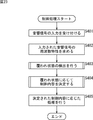
次に、図24のフローチャートを参照して、図23のステップS404において実行される制御内容決定処理の流れの例を説明する。
[Flow of control content determination process]
Next, an example of the flow of control content determination processing executed in step S404 in FIG. 23 will be described with reference to the flowchart in FIG.
制御内容決定処理が開始されると、ステップS441において、覆われ状態蓄積部161は、覆われ検出部103から供給される覆われ状態情報を記憶する。
When the control content determination process is started, in step S441, the covered
ステップS442において、制御内容決定部162は、その覆われ状態蓄積部161に蓄積される覆われ状態情報に基づいて、音響信号入力部101がユーザの手等により覆われている時間である覆われ期間(例えば、上述したt2 - t1)を検出する。
In step S442, the control
ステップS443において、制御内容決定部162は、通話状態通知部411からの通知に基づいて、通話状態を判定する。
In step S443, the control
ステップS444において、制御内容決定部162は、ステップS442およびステップS443の処理結果に基づいて、覆われ期間が所定の長さ(時間閾値T)より長く、かつ、通話中であるか否かを判定する。覆われ期間が所定の長さ(時間閾値T)より長く、かつ、通話中であると判定された場合、制御内容決定部162は、処理をステップS445に進める。
In step S444, the control
ステップS445において、制御内容決定部162は、制御部414に制御情報を供給し、受話音量を小さくするように制御させる。ステップS445の処理を終了すると、制御内容決定部162は、制御内容決定処理を終了し、処理を図23のステップS404に戻し、ステップS405以降の処理を実行させる。
In step S445, the control
また、図24のステップS444において、覆われ期間が所定の長さ(時間閾値T)より長くない、若しくは、非通話中であると判定された場合、制御内容決定部162は、処理をステップS446に進める。
If it is determined in step S444 in FIG. 24 that the covered period is not longer than the predetermined length (time threshold T) or is not in a call, the control
ステップS446において、制御内容決定部162は、ステップS442およびステップS443の処理結果に基づいて、覆われ期間が所定の長さ(時間閾値T)より長く、かつ、非通話中であるか否かを判定する。覆われ期間が所定の長さ(時間閾値T)より長く、かつ、非通話中であると判定された場合、制御内容決定部162は、処理をステップS447に進める。
In step S446, the control
ステップS447において、制御内容決定部162は、音声波形蓄積部412を制御し、音声波形蓄積部412に蓄積されている覆われ期間の入力音の電気信号を、音声認識部413に供給させ、音声認識部413に音声認識を行わせる。
In step S447, the control
ステップS448において、制御内容決定部162は、その音声認識結果に基づいて、制御内容を決定し、その制御情報を制御部414に供給し、その音声認識処理に対応する処理が実行されるように制御させる。ステップS448の処理を終了すると、制御内容決定部162は、制御内容決定処理を終了し、処理を図23のステップS404に戻し、ステップS405以降の処理を実行させる。
In step S <b> 448, the control
また、図24のステップS444において、覆われ期間が所定の長さ(時間閾値T)より長くないと判定された場合、制御内容決定部162は、制御内容決定処理を終了し、処理を図23のステップS404に戻し、ステップS405以降の処理を実行させる。
If it is determined in step S444 in FIG. 24 that the covered period is not longer than the predetermined length (time threshold value T), the control
以上のような各処理を実行することにより、携帯電話機400は、ユーザが、発音することなく、かつ、非接触な操作で、携帯電話機400の制御に関する指示を入力することができるようにすることができる。 By executing the processes as described above, the mobile phone 400 enables the user to input instructions related to control of the mobile phone 400 without generating a sound and performing a non-contact operation. Can do.
以上においては、携帯電話機に制御装置100を適用する場合について説明したが、制御装置100の代わりに制御装置200を適用するようにしてももちろんよい。 In the above description, the case where the control device 100 is applied to a mobile phone has been described. However, the control device 200 may be applied instead of the control device 100.
なお、本発明を適用した制御装置100および制御装置200は、携帯電話機以外の電子機器にも適用することができる。例えば、音声認識装置やICレコーダ等に適用することもできる。 Note that the control device 100 and the control device 200 to which the present invention is applied can also be applied to electronic devices other than mobile phones. For example, the present invention can be applied to a voice recognition device, an IC recorder, and the like.
例えば、一般に現在の音声認識装置では、認識させたい音声の区間を何らかの手法で特定するPush-To-Talkと呼ばれる手法が用いられることが多い。これは、ユーザが発話する際にボタンのようなものを押してから発話するというものである。 For example, in general, current speech recognition apparatuses often use a technique called Push-To-Talk that identifies a speech segment to be recognized by some technique. This means that the user speaks after pressing a button or the like when speaking.
このボタンの代わりに、制御装置100や制御装置200を適用することにより、ユーザが、発話に利用するマイクロホンを軽く手で覆う等の非接触な操作を行うことにより、ボタン操作の代わりとすることができる。このようにすることでPush-To-Talk用のボタンを設ける必要がなくなり、音声認識装置の製造コストを低減させることができる。 By applying the control device 100 or the control device 200 instead of this button, the user can perform a non-contact operation such as lightly covering the microphone used for speech with a hand, thereby replacing the button operation. Can do. By doing so, there is no need to provide a push-to-talk button, and the manufacturing cost of the speech recognition apparatus can be reduced.
なお、この場合、ユーザは、手をマイクロホンに接触させる必要が無いので、手等をマイクロホンにかざした状態(マイクロホンが覆われた状態)のまま、発話することができる(この状態においても、マイクロホンはユーザの発話を十分に集音することができる)。 In this case, since the user does not need to bring his hand into contact with the microphone, he / she can speak while holding the hand or the like over the microphone (the microphone is covered). Can collect enough user utterances).
これに対して、例えば、マイクロホンを指で叩く等、マイクロホンに接触する必要がある場合、発話する前にその手をマイクロホンから離す必要があるので、煩雑な作業が必要になる。また、接触することにより雑音が発生するので、発話の立ち上がりの音声を、雑音の少ない好ましい状態で集音することが困難になる恐れもあり、音声認識処理の精度を低減させてしまう恐れもある。 On the other hand, for example, when it is necessary to touch the microphone, for example, when the microphone is hit with a finger, it is necessary to remove the hand from the microphone before speaking, which requires complicated work. In addition, since noise is generated by contact, there is a risk that it may be difficult to collect the voice at the beginning of the utterance in a preferable state with less noise, and the accuracy of the voice recognition processing may be reduced. .
本発明を適用することにより、非接触な操作を実現することができるので、音声認識装置は、立ち上がりの音声から、雑音の少ない好ましい状態で集音を行うことができる。 By applying the present invention, a non-contact operation can be realized, so that the voice recognition apparatus can collect sound from a rising voice in a preferable state with little noise.
また、ICレコーダに本発明の制御装置100や制御装置200を適用することもできる。その場合、例えば、ICレコーダに設けられた集音(録音)に用いられるマイクロホンを、音響信号入力部101として利用することができる。
Further, the control device 100 or the control device 200 of the present invention can be applied to an IC recorder. In that case, for example, a microphone used for sound collection (recording) provided in the IC recorder can be used as the acoustic
例えば、マイクロホンが短い時間覆われた場合、一時停止し、マイクロホンが長い時間覆われた場合、録音中なら停止、停止中なら録音開始するようにしてもよい。 For example, when the microphone is covered for a short time, it may be paused, and when the microphone is covered for a long time, the recording may be stopped during recording, and the recording may be started when stopped.
このように、ICレコーダに関する動作を、制御内容として覆われ状態に割り当てることにより、ユーザは、ICレコーダ本体に触れることなくICレコーダを操作することができる。したがって、音声認識装置の場合と同様に、製造コストを低減させることができるだけでなく、ユーザが操作のためにマイクロホン等に触れることにより、雑音が録音されることを抑制することができる。 In this way, by assigning the operation related to the IC recorder to the covered state as the control content, the user can operate the IC recorder without touching the IC recorder main body. Therefore, as in the case of the voice recognition device, not only can the manufacturing cost be reduced, but also it is possible to prevent noise from being recorded when the user touches a microphone or the like for operation.
もちろん、本発明を適用した制御装置は、上述した以外の任意の電子機器に適用することができる。 Of course, the control apparatus to which the present invention is applied can be applied to any electronic apparatus other than those described above.
<5.第5の実施の形態>
[パーソナルコンピュータ]
上述した一連の処理は、ハードウェアにより実行させることもできるし、ソフトウェアにより実行させることもできる。この場合、例えば、図25に示されるようなパーソナルコンピュータとして構成されるようにしてもよい。
<5. Fifth embodiment>
[Personal computer]
The series of processes described above can be executed by hardware or can be executed by software. In this case, for example, a personal computer as shown in FIG. 25 may be configured.
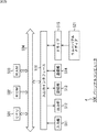
図25において、パーソナルコンピュータ500のCPU(Central Processing Unit)501は、ROM(Read Only Memory)502に記憶されているプログラム、または記憶部513からRAM503にロードされたプログラムに従って各種の処理を実行する。RAM503にはまた、CPU501が各種の処理を実行する上において必要なデータなども適宜記憶される。
25, a CPU (Central Processing Unit) 501 of the personal computer 500 executes various processes according to a program stored in a ROM (Read Only Memory) 502 or a program loaded from the
CPU501、ROM502、およびRAM503は、バス504を介して相互に接続されている。このバス504にはまた、入出力インタフェース510も接続されている。
The
入出力インタフェース510には、キーボード、マウスなどよりなる入力部511、CRT(Cathode Ray Tube)ディスプレイやLCD(Liquid Crystal Display)等のディスプレイ、並びにスピーカなどよりなる出力部512、フラッシュメモリ等SSD(Solid State Drive)やハードディスクなどよりなる記憶部513、有線LAN(Local Area Network)や無線LANのインタフェースやモデムなどよりなる通信部514が接続されている。通信部514は、インターネットを含むネットワークを介しての通信処理を行う。
The input /
入出力インタフェース510にはまた、必要に応じてドライブ515が接続され、磁気ディスク、光ディスク、光磁気ディスク、或いは半導体メモリなどのリムーバブルメディア521が適宜装着され、それらから読み出されたコンピュータプログラムが、必要に応じて記憶部513にインストールされる。
A
上述した一連の処理をソフトウェアにより実行させる場合には、そのソフトウェアを構成するプログラムが、ネットワークや記録媒体からインストールされる。 When the above-described series of processing is executed by software, a program constituting the software is installed from a network or a recording medium.
この記録媒体は、例えば、図25に示されるように、装置本体とは別に、ユーザにプログラムを配信するために配布される、プログラムが記録されている磁気ディスク(フレキシブルディスクを含む)、光ディスク(CD-ROM(Compact Disc - Read Only Memory),DVD(Digital Versatile Disc)を含む)、光磁気ディスク(MD(Mini Disc)を含む)、若しくは半導体メモリなどよりなるリムーバブルメディア521により構成されるだけでなく、装置本体に予め組み込まれた状態でユーザに配信される、プログラムが記録されているROM502や、記憶部513に含まれるハードディスクなどにより構成される。
For example, as shown in FIG. 25, this recording medium is distributed to distribute a program to a user separately from the apparatus main body, and includes a magnetic disk (including a flexible disk) on which a program is recorded, an optical disk ( It only consists of
なお、コンピュータが実行するプログラムは、本明細書で説明する順序に沿って時系列に処理が行われるプログラムであっても良いし、並列に、あるいは呼び出しが行われたとき等の必要なタイミングで処理が行われるプログラムであっても良い。 The program executed by the computer may be a program that is processed in time series in the order described in this specification, or in parallel or at a necessary timing such as when a call is made. It may be a program for processing.
また、本明細書において、記録媒体に記録されるプログラムを記述するステップは、記載された順序に沿って時系列的に行われる処理はもちろん、必ずしも時系列的に処理されなくとも、並列的あるいは個別に実行される処理をも含むものである。 Further, in the present specification, the step of describing the program recorded on the recording medium is not limited to the processing performed in chronological order according to the described order, but may be performed in parallel or It also includes processes that are executed individually.
また、本明細書において、システムとは、複数のデバイス(装置)により構成される装置全体を表すものである。 Further, in this specification, the system represents the entire apparatus composed of a plurality of devices (apparatuses).
また、以上において、1つの装置(または処理部)として説明した構成が、複数の装置(または処理部)として構成されるようにしてもよい。逆に、以上において複数の装置(または処理部)として説明した構成が、まとめて1つの装置(または処理部)として構成されるようにしてもよい。また、各装置(または各処理部)の構成に上述した以外の構成が付加されるようにしてももちろんよい。さらに、システム全体としての構成や動作が実質的に同じであれば、ある装置(または処理部)の構成の一部が他の装置(または他の処理部)の構成に含まれるようにしてもよい。つまり、本発明の実施の形態は、上述した実施の形態に限定されるものではなく、本発明の要旨を逸脱しない範囲において種々の変更が可能である。 In addition, in the above description, the configuration described as one device (or processing unit) may be configured as a plurality of devices (or processing units). Conversely, the configuration described above as a plurality of devices (or processing units) may be configured as a single device (or processing unit). Of course, a configuration other than that described above may be added to the configuration of each device (or each processing unit). Further, if the configuration and operation of the entire system are substantially the same, a part of the configuration of a certain device (or processing unit) may be included in the configuration of another device (or other processing unit). Good. That is, the embodiment of the present invention is not limited to the above-described embodiment, and various modifications can be made without departing from the gist of the present invention.
100 制御装置, 101 音響信号入力部, 102 時間周波数変換部, 103 覆われ検出部, 104 機器制御決定部, 111 周波数特性蓄積部, 112 覆われ特徴量算出部, 113 覆われ状態検出部, 161 覆われ状態蓄積部, 162 制御内容決定部, 200 制御装置, 203 覆われ検出部, 211 周波数特性蓄積部, 212 差分算出部, 300 携帯型音楽再生装置, 304 機器制御決定部, 305 制御部, 400 携帯電話機, 404 機器制御決定部, 411 通話状態通知部, 412 音声波形蓄積部, 413 音声認識部, 414 制御部 DESCRIPTION OF SYMBOLS 100 Control apparatus, 101 Acoustic signal input part, 102 Time frequency conversion part, 103 Covered detection part, 104 Equipment control determination part, 111 Frequency characteristic storage part, 112 Covered feature-value calculation part, 113 Covered state detection part, 161 Covered state storage unit, 162 Control content determination unit, 200 control device, 203 Covered detection unit, 211 Frequency characteristic storage unit, 212 Difference calculation unit, 300 Portable music player, 304 Device control determination unit, 305 Control unit, 400 mobile phone, 404 device control determination unit, 411 call state notification unit, 412 voice waveform storage unit, 413 voice recognition unit, 414 control unit
Claims (14)
前記集音手段により集音されて得られた音響信号の周波数特性における共振周波数および前記共振周波数の成分の大きさに基づいて、前記集音手段の覆われ状態を検出する覆われ検出手段と、
前記覆われ検出手段により検出された前記集音手段の覆われ状態に応じて、制御対象の機器の制御内容を決定する機器制御決定手段と
を備える信号処理装置。 Sound collecting means for collecting sound;
Covered detection means for detecting the covered state of the sound collection means based on the resonance frequency in the frequency characteristics of the acoustic signal obtained by collecting the sound by the sound collection means and the magnitude of the component of the resonance frequency;
A signal processing apparatus comprising: device control determining means for determining control contents of a device to be controlled in accordance with a covering state of the sound collecting means detected by the covering detecting means.
請求項1に記載の信号処理装置。 The signal processing apparatus according to claim 1, wherein the covering detection unit detects whether or not the sound collecting unit is covered or a degree to which the sound collecting unit is covered.
請求項1に記載の信号処理装置。 The signal according to claim 1, wherein the covering detection unit compares the resonance frequency and the magnitude of the component of the resonance frequency with a predetermined threshold and detects the covering state of the sound collecting unit according to the comparison result. Processing equipment.
請求項1に記載の信号処理装置。 The covering detection means adds the resonance frequency and the magnitude of the component of the resonance frequency in the frequency characteristics of the acoustic signal at a plurality of times, and detects the covering state of the sound collecting means based on the addition result The signal processing apparatus according to claim 1.
請求項1に記載の信号処理装置。 The signal processing apparatus according to claim 1, wherein the device control determining unit determines the control content according to whether or not the sound collecting unit is covered or a degree to which the sound collecting unit is covered.
請求項1に記載の信号処理装置。 The signal processing apparatus according to claim 1, wherein the device control determining unit determines the control content according to a time during which the sound collecting unit is covered.
請求項1に記載の信号処理装置。 The signal processing apparatus according to claim 1, wherein the device control determination unit determines a control amount of the control content according to a degree to which the sound collection unit is covered.
請求項1に記載の信号処理装置。 The signal processing apparatus according to claim 1, comprising a plurality of the sound collecting means.
前記覆われ検出手段は、前記差分算出手段により算出された前記差分における前記共振周波数および前記共振周波数の成分の大きさに基づいて、前記集音手段の覆われ状態を検出する
請求項8に記載の信号処理装置。 A difference calculating means for calculating a difference in frequency characteristics of the acoustic signal obtained in each of the plurality of sound collecting means;
9. The cover detection unit detects a cover state of the sound collecting unit based on the resonance frequency and the component of the resonance frequency in the difference calculated by the difference calculation unit. Signal processing equipment.
請求項8に記載の信号処理装置。 The signal processing apparatus according to claim 8, wherein the device control determining unit assigns different control contents to the same covered state of the sound collecting units.
前記覆われ検出手段は、前記集音手段により前記通話処理のために集音されて得られた音響信号の周波数特性における共振周波数および前記共振周波数の成分の大きさに基づいて、前記集音手段の覆われ状態を検出する
請求項1に記載の信号処理装置。 The sound collecting means collects sound for call processing,
The covering detection means is based on a resonance frequency in a frequency characteristic of an acoustic signal obtained by collecting sound for the call processing by the sound collection means and a magnitude of a component of the resonance frequency. The signal processing device according to claim 1, wherein a signal covering state is detected.
前記機器制御決定手段は、前記覆われ検出手段により検出された前記集音手段の覆われ状態、および、前記音声認識処理手段による前記音声認識処理の結果に応じて、前記制御内容を決定する
請求項1に記載の信号処理装置。 Voice recognition processing means for performing voice recognition processing on the acoustic signal obtained by collecting the sound by the sound collecting means;
The device control determining unit determines the control content according to a covering state of the sound collecting unit detected by the covering detecting unit and a result of the voice recognition processing by the voice recognition processing unit. Item 2. The signal processing device according to Item 1.
集音手段が、集音し、
覆われ検出手段が、集音されて得られた音響信号の周波数特性における共振周波数および前記共振周波数の成分の大きさに基づいて、前記集音手段の覆われ状態を検出し、
機器制御決定手段が、検出された前記集音手段の覆われ状態に応じて、制御対象の機器の制御内容を決定する
信号処理方法。 A signal processing method for a signal processing device, comprising:
The sound collection means collects the sound
The covering detection means detects the covering state of the sound collecting means based on the resonance frequency in the frequency characteristic of the acoustic signal obtained by collecting the sound and the magnitude of the component of the resonance frequency,
A signal processing method in which device control determining means determines the control content of a device to be controlled according to the detected covering state of the sound collecting means.
集音する集音手段、
前記集音手段により集音されて得られた音響信号の周波数特性における共振周波数および前記共振周波数の成分の大きさに基づいて、前記集音手段の覆われ状態を検出する覆われ検出手段、
前記覆われ検出手段により検出された前記集音手段の覆われ状態に応じて、制御対象の機器の制御内容を決定する機器制御決定手段
として機能させるためのプログラム。 Computer
Sound collecting means for collecting sound,
Covered detection means for detecting the covered state of the sound collecting means based on the resonance frequency in the frequency characteristics of the acoustic signal obtained by collecting the sound by the sound collecting means and the magnitude of the component of the resonance frequency;
A program for functioning as device control determining means for determining control contents of a device to be controlled in accordance with a covering state of the sound collecting means detected by the covering detecting means.
Priority Applications (3)
| Application Number | Priority Date | Filing Date | Title |
|---|---|---|---|
| JP2011016398A JP2012155651A (en) | 2011-01-28 | 2011-01-28 | Signal processing device and method, and program |
| US13/354,126 US20120197420A1 (en) | 2011-01-28 | 2012-01-19 | Signal processing device, signal processing method, and program |
| CN2012100193132A CN102625203A (en) | 2011-01-28 | 2012-01-20 | Signal processing device, signal processing method, and program |
Applications Claiming Priority (1)
| Application Number | Priority Date | Filing Date | Title |
|---|---|---|---|
| JP2011016398A JP2012155651A (en) | 2011-01-28 | 2011-01-28 | Signal processing device and method, and program |
Publications (2)
| Publication Number | Publication Date |
|---|---|
| JP2012155651A true JP2012155651A (en) | 2012-08-16 |
| JP2012155651A5 JP2012155651A5 (en) | 2014-02-27 |
Family
ID=46564855
Family Applications (1)
| Application Number | Title | Priority Date | Filing Date |
|---|---|---|---|
| JP2011016398A Pending JP2012155651A (en) | 2011-01-28 | 2011-01-28 | Signal processing device and method, and program |
Country Status (3)
| Country | Link |
|---|---|
| US (1) | US20120197420A1 (en) |
| JP (1) | JP2012155651A (en) |
| CN (1) | CN102625203A (en) |
Cited By (6)
| Publication number | Priority date | Publication date | Assignee | Title |
|---|---|---|---|---|
| WO2014147785A1 (en) * | 2013-03-21 | 2014-09-25 | 富士通株式会社 | Movement detection device, movement detection method, program, and recording medium |
| JP2014204318A (en) * | 2013-04-05 | 2014-10-27 | パナソニック株式会社 | Mobile terminal device |
| JP2016127502A (en) * | 2015-01-06 | 2016-07-11 | 富士通株式会社 | Communication device and program |
| JP2017527163A (en) * | 2014-06-30 | 2017-09-14 | ゼットティーイー コーポレーションZte Corporation | Method and apparatus for selecting a main microphone |
| JP2018142949A (en) * | 2017-02-28 | 2018-09-13 | パナソニック インテレクチュアル プロパティ コーポレーション オブ アメリカPanasonic Intellectual Property Corporation of America | Sound collecting apparatus, sound collection method, program, and imaging apparatus |
| JP2020108166A (en) * | 2016-04-11 | 2020-07-09 | ソニー株式会社 | Headphone, reproduction control method, and program |
Families Citing this family (7)
| Publication number | Priority date | Publication date | Assignee | Title |
|---|---|---|---|---|
| JP2013205830A (en) * | 2012-03-29 | 2013-10-07 | Sony Corp | Tonal component detection method, tonal component detection apparatus, and program |
| US20140044286A1 (en) * | 2012-08-10 | 2014-02-13 | Motorola Mobility Llc | Dynamic speaker selection for mobile computing devices |
| JP2014175993A (en) * | 2013-03-12 | 2014-09-22 | Sony Corp | Notification controller, notification control method, and program |
| JP7192348B2 (en) * | 2018-09-25 | 2022-12-20 | 富士フイルムビジネスイノベーション株式会社 | Control device, control system and program |
| US10623845B1 (en) * | 2018-12-17 | 2020-04-14 | Qualcomm Incorporated | Acoustic gesture detection for control of a hearable device |
| KR102652553B1 (en) * | 2019-02-08 | 2024-03-29 | 삼성전자 주식회사 | Electronic device and method for detecting block of microphone |
| CN116266893B (en) * | 2021-12-16 | 2026-04-28 | 华为技术有限公司 | Headphone control methods and related systems, storage media |
Citations (3)
| Publication number | Priority date | Publication date | Assignee | Title |
|---|---|---|---|---|
| JP2001512732A (en) * | 1997-08-05 | 2001-08-28 | ザ ステーリン ファンデーション フォー キャンサー リサーチ (The Stehlin Foundation for Cancer Research) | Preparation and purification method of 9-nitro-20-camptothecin (9-NITRO-20-CAMPTOTHECIN) |
| JP2004347866A (en) * | 2003-05-22 | 2004-12-09 | Sony Corp | Control device and control method for controlled device |
| WO2010125797A1 (en) * | 2009-04-28 | 2010-11-04 | パナソニック株式会社 | Hearing aid device and hearing aid method |
Family Cites Families (3)
| Publication number | Priority date | Publication date | Assignee | Title |
|---|---|---|---|---|
| EP1298959A3 (en) * | 2001-09-24 | 2006-04-19 | Siemens Audiologische Technik GmbH | Hearing aid with parasitic signal control |
| JP2006087018A (en) * | 2004-09-17 | 2006-03-30 | Matsushita Electric Ind Co Ltd | Sound processor |
| US8374362B2 (en) * | 2008-01-31 | 2013-02-12 | Qualcomm Incorporated | Signaling microphone covering to the user |
-
2011
- 2011-01-28 JP JP2011016398A patent/JP2012155651A/en active Pending
-
2012
- 2012-01-19 US US13/354,126 patent/US20120197420A1/en not_active Abandoned
- 2012-01-20 CN CN2012100193132A patent/CN102625203A/en active Pending
Patent Citations (3)
| Publication number | Priority date | Publication date | Assignee | Title |
|---|---|---|---|---|
| JP2001512732A (en) * | 1997-08-05 | 2001-08-28 | ザ ステーリン ファンデーション フォー キャンサー リサーチ (The Stehlin Foundation for Cancer Research) | Preparation and purification method of 9-nitro-20-camptothecin (9-NITRO-20-CAMPTOTHECIN) |
| JP2004347866A (en) * | 2003-05-22 | 2004-12-09 | Sony Corp | Control device and control method for controlled device |
| WO2010125797A1 (en) * | 2009-04-28 | 2010-11-04 | パナソニック株式会社 | Hearing aid device and hearing aid method |
Cited By (9)
| Publication number | Priority date | Publication date | Assignee | Title |
|---|---|---|---|---|
| WO2014147785A1 (en) * | 2013-03-21 | 2014-09-25 | 富士通株式会社 | Movement detection device, movement detection method, program, and recording medium |
| JP6032350B2 (en) * | 2013-03-21 | 2016-11-24 | 富士通株式会社 | Motion detection device and motion detection method |
| JP2014204318A (en) * | 2013-04-05 | 2014-10-27 | パナソニック株式会社 | Mobile terminal device |
| JP2017527163A (en) * | 2014-06-30 | 2017-09-14 | ゼットティーイー コーポレーションZte Corporation | Method and apparatus for selecting a main microphone |
| JP2016127502A (en) * | 2015-01-06 | 2016-07-11 | 富士通株式会社 | Communication device and program |
| JP2020108166A (en) * | 2016-04-11 | 2020-07-09 | ソニー株式会社 | Headphone, reproduction control method, and program |
| US11290803B2 (en) | 2016-04-11 | 2022-03-29 | Sony Corporation | Headphone, reproduction control method, and program |
| JP2018142949A (en) * | 2017-02-28 | 2018-09-13 | パナソニック インテレクチュアル プロパティ コーポレーション オブ アメリカPanasonic Intellectual Property Corporation of America | Sound collecting apparatus, sound collection method, program, and imaging apparatus |
| JP7009165B2 (en) | 2017-02-28 | 2022-01-25 | パナソニック インテレクチュアル プロパティ コーポレーション オブ アメリカ | Sound pickup device, sound collection method, program and image pickup device |
Also Published As
| Publication number | Publication date |
|---|---|
| US20120197420A1 (en) | 2012-08-02 |
| CN102625203A (en) | 2012-08-01 |
Similar Documents
| Publication | Publication Date | Title |
|---|---|---|
| US20120197420A1 (en) | Signal processing device, signal processing method, and program | |
| US10824391B2 (en) | Audio user interface apparatus and method | |
| US20210035563A1 (en) | Per-epoch data augmentation for training acoustic models | |
| EP3090429B1 (en) | Modifying operations based on acoustic ambience classification | |
| US10566012B1 (en) | Direction based end-pointing for speech recognition | |
| US9837068B2 (en) | Sound sample verification for generating sound detection model | |
| JP6844608B2 (en) | Voice processing device and voice processing method | |
| CN102842304B (en) | Voice data transferring device, transferring method, terminal device and voice recognition system | |
| US20140200890A1 (en) | Methods, systems, and circuits for speaker dependent voice recognition with a single lexicon | |
| JP2021503633A (en) | Voice noise reduction methods, devices, servers and storage media | |
| US11290802B1 (en) | Voice detection using hearable devices | |
| CN102047688A (en) | Systems, methods and devices for multi-channel signal balancing | |
| JP5411807B2 (en) | Channel integration method, channel integration apparatus, and program | |
| US11895474B2 (en) | Activity detection on devices with multi-modal sensing | |
| CN105580071A (en) | Method and apparatus for training a voice recognition model database | |
| WO2014172167A1 (en) | Vocal keyword training from text | |
| JP6182895B2 (en) | Processing apparatus, processing method, program, and processing system | |
| CN114678038B (en) | Audio noise detection method, computer device and computer program product | |
| US10142730B1 (en) | Temporal and spatial detection of acoustic sources | |
| CN115398422A (en) | Adaptive music selection using machine learning of noise features, music features, and related user actions | |
| JP2015169827A (en) | Speech processing device, speech processing method, and speech processing program | |
| JP6723033B2 (en) | Information processing device, information processing system, server, terminal device, information processing method, and program | |
| JP5375869B2 (en) | Music playback device, music playback method and program | |
| KR102102387B1 (en) | Method and System for detecting User's utterance in a multi-channel audio environment | |
| JP2020042173A (en) | Continuous utterance estimation device, continuous utterance estimation method, and program |
Legal Events
| Date | Code | Title | Description |
|---|---|---|---|
| A521 | Request for written amendment filed |
Free format text: JAPANESE INTERMEDIATE CODE: A523 Effective date: 20140109 |
|
| A621 | Written request for application examination |
Free format text: JAPANESE INTERMEDIATE CODE: A621 Effective date: 20140109 |
|
| A131 | Notification of reasons for refusal |
Free format text: JAPANESE INTERMEDIATE CODE: A131 Effective date: 20140826 |
|
| A977 | Report on retrieval |
Free format text: JAPANESE INTERMEDIATE CODE: A971007 Effective date: 20140827 |
|
| A02 | Decision of refusal |
Free format text: JAPANESE INTERMEDIATE CODE: A02 Effective date: 20150326 |