JP2012155992A - Method for using nonaqueous electrolyte iodine battery - Google Patents
Method for using nonaqueous electrolyte iodine battery Download PDFInfo
- Publication number
- JP2012155992A JP2012155992A JP2011013937A JP2011013937A JP2012155992A JP 2012155992 A JP2012155992 A JP 2012155992A JP 2011013937 A JP2011013937 A JP 2011013937A JP 2011013937 A JP2011013937 A JP 2011013937A JP 2012155992 A JP2012155992 A JP 2012155992A
- Authority
- JP
- Japan
- Prior art keywords
- iodine
- positive electrode
- charging
- lithium
- battery
- Prior art date
- Legal status (The legal status is an assumption and is not a legal conclusion. Google has not performed a legal analysis and makes no representation as to the accuracy of the status listed.)
- Pending
Links
- 239000011630 iodine Substances 0.000 title claims abstract description 98
- 229910052740 iodine Inorganic materials 0.000 title claims abstract description 98
- ZCYVEMRRCGMTRW-UHFFFAOYSA-N 7553-56-2 Chemical compound [I] ZCYVEMRRCGMTRW-UHFFFAOYSA-N 0.000 title claims abstract description 97
- 239000011255 nonaqueous electrolyte Substances 0.000 title claims abstract description 42
- 238000000034 method Methods 0.000 title claims abstract description 19
- 238000006243 chemical reaction Methods 0.000 claims abstract description 82
- 238000007600 charging Methods 0.000 claims abstract description 67
- 238000007599 discharging Methods 0.000 claims abstract description 44
- 229910052744 lithium Inorganic materials 0.000 claims abstract description 36
- HBBGRARXTFLTSG-UHFFFAOYSA-N Lithium ion Chemical compound [Li+] HBBGRARXTFLTSG-UHFFFAOYSA-N 0.000 claims abstract description 32
- 229910001416 lithium ion Inorganic materials 0.000 claims abstract description 32
- 150000002500 ions Chemical class 0.000 claims abstract description 17
- WHXSMMKQMYFTQS-UHFFFAOYSA-N Lithium Chemical compound [Li] WHXSMMKQMYFTQS-UHFFFAOYSA-N 0.000 claims description 34
- 239000007774 positive electrode material Substances 0.000 claims description 14
- 239000007773 negative electrode material Substances 0.000 claims description 9
- 239000000463 material Substances 0.000 claims description 3
- 239000008151 electrolyte solution Substances 0.000 abstract description 16
- 239000011230 binding agent Substances 0.000 abstract description 13
- 239000004020 conductor Substances 0.000 abstract description 12
- -1 lithium hexafluorophosphate Chemical compound 0.000 abstract description 12
- 239000003792 electrolyte Substances 0.000 abstract description 10
- BASFCYQUMIYNBI-UHFFFAOYSA-N platinum Chemical compound [Pt] BASFCYQUMIYNBI-UHFFFAOYSA-N 0.000 abstract description 5
- 238000002156 mixing Methods 0.000 abstract description 4
- 239000011888 foil Substances 0.000 abstract description 3
- 239000000243 solution Substances 0.000 abstract description 3
- 229910003002 lithium salt Inorganic materials 0.000 abstract description 2
- 159000000002 lithium salts Chemical class 0.000 abstract description 2
- 238000000465 moulding Methods 0.000 abstract description 2
- 229910052697 platinum Inorganic materials 0.000 abstract description 2
- 208000028659 discharge Diseases 0.000 description 63
- 238000011156 evaluation Methods 0.000 description 15
- NUJOXMJBOLGQSY-UHFFFAOYSA-N manganese dioxide Chemical compound O=[Mn]=O NUJOXMJBOLGQSY-UHFFFAOYSA-N 0.000 description 10
- OKTJSMMVPCPJKN-UHFFFAOYSA-N Carbon Chemical compound [C] OKTJSMMVPCPJKN-UHFFFAOYSA-N 0.000 description 8
- PXHVJJICTQNCMI-UHFFFAOYSA-N Nickel Chemical compound [Ni] PXHVJJICTQNCMI-UHFFFAOYSA-N 0.000 description 8
- 239000003054 catalyst Substances 0.000 description 7
- PNDPGZBMCMUPRI-UHFFFAOYSA-N iodine Chemical compound II PNDPGZBMCMUPRI-UHFFFAOYSA-N 0.000 description 7
- 239000000203 mixture Substances 0.000 description 6
- OIFBSDVPJOWBCH-UHFFFAOYSA-N Diethyl carbonate Chemical compound CCOC(=O)OCC OIFBSDVPJOWBCH-UHFFFAOYSA-N 0.000 description 5
- KMTRUDSVKNLOMY-UHFFFAOYSA-N Ethylene carbonate Chemical compound O=C1OCCO1 KMTRUDSVKNLOMY-UHFFFAOYSA-N 0.000 description 5
- 229910052799 carbon Inorganic materials 0.000 description 5
- 230000002427 irreversible effect Effects 0.000 description 5
- 229910052751 metal Inorganic materials 0.000 description 5
- 239000002184 metal Substances 0.000 description 5
- 150000003839 salts Chemical class 0.000 description 5
- 239000002904 solvent Substances 0.000 description 5
- 230000007423 decrease Effects 0.000 description 4
- 230000005611 electricity Effects 0.000 description 4
- 238000003487 electrochemical reaction Methods 0.000 description 4
- 230000033116 oxidation-reduction process Effects 0.000 description 4
- 230000002441 reversible effect Effects 0.000 description 4
- ZWEHNKRNPOVVGH-UHFFFAOYSA-N 2-Butanone Chemical compound CCC(C)=O ZWEHNKRNPOVVGH-UHFFFAOYSA-N 0.000 description 3
- YEJRWHAVMIAJKC-UHFFFAOYSA-N 4-Butyrolactone Chemical compound O=C1CCCO1 YEJRWHAVMIAJKC-UHFFFAOYSA-N 0.000 description 3
- RYGMFSIKBFXOCR-UHFFFAOYSA-N Copper Chemical compound [Cu] RYGMFSIKBFXOCR-UHFFFAOYSA-N 0.000 description 3
- 229910000733 Li alloy Inorganic materials 0.000 description 3
- ZMXDDKWLCZADIW-UHFFFAOYSA-N N,N-Dimethylformamide Chemical compound CN(C)C=O ZMXDDKWLCZADIW-UHFFFAOYSA-N 0.000 description 3
- 239000002033 PVDF binder Substances 0.000 description 3
- 239000004809 Teflon Substances 0.000 description 3
- 229920006362 Teflon® Polymers 0.000 description 3
- 229910052802 copper Inorganic materials 0.000 description 3
- 239000010949 copper Substances 0.000 description 3
- 238000004146 energy storage Methods 0.000 description 3
- 229910052759 nickel Inorganic materials 0.000 description 3
- 229920002981 polyvinylidene fluoride Polymers 0.000 description 3
- 238000006722 reduction reaction Methods 0.000 description 3
- XLYOFNOQVPJJNP-UHFFFAOYSA-N water Substances O XLYOFNOQVPJJNP-UHFFFAOYSA-N 0.000 description 3
- OOWFYDWAMOKVSF-UHFFFAOYSA-N 3-methoxypropanenitrile Chemical compound COCCC#N OOWFYDWAMOKVSF-UHFFFAOYSA-N 0.000 description 2
- XKRFYHLGVUSROY-UHFFFAOYSA-N Argon Chemical compound [Ar] XKRFYHLGVUSROY-UHFFFAOYSA-N 0.000 description 2
- 229920000049 Carbon (fiber) Polymers 0.000 description 2
- IAYPIBMASNFSPL-UHFFFAOYSA-N Ethylene oxide Chemical compound C1CO1 IAYPIBMASNFSPL-UHFFFAOYSA-N 0.000 description 2
- YCKRFDGAMUMZLT-UHFFFAOYSA-N Fluorine atom Chemical compound [F] YCKRFDGAMUMZLT-UHFFFAOYSA-N 0.000 description 2
- BAPJBEWLBFYGME-UHFFFAOYSA-N Methyl acrylate Chemical compound COC(=O)C=C BAPJBEWLBFYGME-UHFFFAOYSA-N 0.000 description 2
- BQCADISMDOOEFD-UHFFFAOYSA-N Silver Chemical compound [Ag] BQCADISMDOOEFD-UHFFFAOYSA-N 0.000 description 2
- WYURNTSHIVDZCO-UHFFFAOYSA-N Tetrahydrofuran Chemical compound C1CCOC1 WYURNTSHIVDZCO-UHFFFAOYSA-N 0.000 description 2
- RTAQQCXQSZGOHL-UHFFFAOYSA-N Titanium Chemical compound [Ti] RTAQQCXQSZGOHL-UHFFFAOYSA-N 0.000 description 2
- ZRXYMHTYEQQBLN-UHFFFAOYSA-N [Br].[Zn] Chemical compound [Br].[Zn] ZRXYMHTYEQQBLN-UHFFFAOYSA-N 0.000 description 2
- 239000011149 active material Substances 0.000 description 2
- 229910052782 aluminium Inorganic materials 0.000 description 2
- XAGFODPZIPBFFR-UHFFFAOYSA-N aluminium Chemical compound [Al] XAGFODPZIPBFFR-UHFFFAOYSA-N 0.000 description 2
- QVGXLLKOCUKJST-UHFFFAOYSA-N atomic oxygen Chemical compound [O] QVGXLLKOCUKJST-UHFFFAOYSA-N 0.000 description 2
- 239000004917 carbon fiber Substances 0.000 description 2
- 239000003575 carbonaceous material Substances 0.000 description 2
- 239000011248 coating agent Substances 0.000 description 2
- 238000000576 coating method Methods 0.000 description 2
- 229920001940 conductive polymer Polymers 0.000 description 2
- JHIVVAPYMSGYDF-UHFFFAOYSA-N cyclohexanone Chemical compound O=C1CCCCC1 JHIVVAPYMSGYDF-UHFFFAOYSA-N 0.000 description 2
- 230000003247 decreasing effect Effects 0.000 description 2
- 238000010586 diagram Methods 0.000 description 2
- 230000000694 effects Effects 0.000 description 2
- 229910052731 fluorine Inorganic materials 0.000 description 2
- 239000011737 fluorine Substances 0.000 description 2
- 229910002804 graphite Inorganic materials 0.000 description 2
- 239000010439 graphite Substances 0.000 description 2
- 239000001989 lithium alloy Substances 0.000 description 2
- MHCFAGZWMAWTNR-UHFFFAOYSA-M lithium perchlorate Chemical compound [Li+].[O-]Cl(=O)(=O)=O MHCFAGZWMAWTNR-UHFFFAOYSA-M 0.000 description 2
- 229910001486 lithium perchlorate Inorganic materials 0.000 description 2
- VNWKTOKETHGBQD-UHFFFAOYSA-N methane Chemical compound C VNWKTOKETHGBQD-UHFFFAOYSA-N 0.000 description 2
- 239000003960 organic solvent Substances 0.000 description 2
- 239000001301 oxygen Substances 0.000 description 2
- 229910052760 oxygen Inorganic materials 0.000 description 2
- 239000002245 particle Substances 0.000 description 2
- 229920000642 polymer Polymers 0.000 description 2
- 229920001343 polytetrafluoroethylene Polymers 0.000 description 2
- 239000004810 polytetrafluoroethylene Substances 0.000 description 2
- 239000000047 product Substances 0.000 description 2
- RUOJZAUFBMNUDX-UHFFFAOYSA-N propylene carbonate Chemical compound CC1COC(=O)O1 RUOJZAUFBMNUDX-UHFFFAOYSA-N 0.000 description 2
- 230000002829 reductive effect Effects 0.000 description 2
- 229910052709 silver Inorganic materials 0.000 description 2
- 239000004332 silver Substances 0.000 description 2
- 238000003860 storage Methods 0.000 description 2
- 229920003048 styrene butadiene rubber Polymers 0.000 description 2
- 239000002562 thickening agent Substances 0.000 description 2
- 229910052719 titanium Inorganic materials 0.000 description 2
- 239000010936 titanium Substances 0.000 description 2
- WVDDUSFOSWWJJH-UHFFFAOYSA-N 1-methyl-3-propylimidazol-1-ium Chemical compound CCCN1C=C[N+](C)=C1 WVDDUSFOSWWJJH-UHFFFAOYSA-N 0.000 description 1
- NLHHRLWOUZZQLW-UHFFFAOYSA-N Acrylonitrile Chemical compound C=CC#N NLHHRLWOUZZQLW-UHFFFAOYSA-N 0.000 description 1
- WKBOTKDWSSQWDR-UHFFFAOYSA-N Bromine atom Chemical compound [Br] WKBOTKDWSSQWDR-UHFFFAOYSA-N 0.000 description 1
- OYPRJOBELJOOCE-UHFFFAOYSA-N Calcium Chemical compound [Ca] OYPRJOBELJOOCE-UHFFFAOYSA-N 0.000 description 1
- 229920002134 Carboxymethyl cellulose Polymers 0.000 description 1
- 229910013063 LiBF 4 Inorganic materials 0.000 description 1
- 229910013684 LiClO 4 Inorganic materials 0.000 description 1
- 229910013870 LiPF 6 Inorganic materials 0.000 description 1
- FYYHWMGAXLPEAU-UHFFFAOYSA-N Magnesium Chemical compound [Mg] FYYHWMGAXLPEAU-UHFFFAOYSA-N 0.000 description 1
- VVQNEPGJFQJSBK-UHFFFAOYSA-N Methyl methacrylate Chemical compound COC(=O)C(C)=C VVQNEPGJFQJSBK-UHFFFAOYSA-N 0.000 description 1
- FXHOOIRPVKKKFG-UHFFFAOYSA-N N,N-Dimethylacetamide Chemical compound CN(C)C(C)=O FXHOOIRPVKKKFG-UHFFFAOYSA-N 0.000 description 1
- SECXISVLQFMRJM-UHFFFAOYSA-N N-Methylpyrrolidone Chemical compound CN1CCCC1=O SECXISVLQFMRJM-UHFFFAOYSA-N 0.000 description 1
- WHNWPMSKXPGLAX-UHFFFAOYSA-N N-Vinyl-2-pyrrolidone Chemical compound C=CN1CCCC1=O WHNWPMSKXPGLAX-UHFFFAOYSA-N 0.000 description 1
- 229910021543 Nickel dioxide Inorganic materials 0.000 description 1
- 239000004698 Polyethylene Substances 0.000 description 1
- 239000004743 Polypropylene Substances 0.000 description 1
- XBDQKXXYIPTUBI-UHFFFAOYSA-M Propionate Chemical compound CCC([O-])=O XBDQKXXYIPTUBI-UHFFFAOYSA-M 0.000 description 1
- GOOHAUXETOMSMM-UHFFFAOYSA-N Propylene oxide Chemical compound CC1CO1 GOOHAUXETOMSMM-UHFFFAOYSA-N 0.000 description 1
- XUIMIQQOPSSXEZ-UHFFFAOYSA-N Silicon Chemical compound [Si] XUIMIQQOPSSXEZ-UHFFFAOYSA-N 0.000 description 1
- 239000002174 Styrene-butadiene Substances 0.000 description 1
- ATJFFYVFTNAWJD-UHFFFAOYSA-N Tin Chemical compound [Sn] ATJFFYVFTNAWJD-UHFFFAOYSA-N 0.000 description 1
- XTXRWKRVRITETP-UHFFFAOYSA-N Vinyl acetate Chemical compound CC(=O)OC=C XTXRWKRVRITETP-UHFFFAOYSA-N 0.000 description 1
- HCHKCACWOHOZIP-UHFFFAOYSA-N Zinc Chemical compound [Zn] HCHKCACWOHOZIP-UHFFFAOYSA-N 0.000 description 1
- KXKVLQRXCPHEJC-UHFFFAOYSA-N acetic acid trimethyl ester Natural products COC(C)=O KXKVLQRXCPHEJC-UHFFFAOYSA-N 0.000 description 1
- 239000006230 acetylene black Substances 0.000 description 1
- 230000002411 adverse Effects 0.000 description 1
- 150000001412 amines Chemical class 0.000 description 1
- 229910052786 argon Inorganic materials 0.000 description 1
- 239000012300 argon atmosphere Substances 0.000 description 1
- 239000012298 atmosphere Substances 0.000 description 1
- 229910052728 basic metal Inorganic materials 0.000 description 1
- 150000003818 basic metals Chemical class 0.000 description 1
- GDTBXPJZTBHREO-UHFFFAOYSA-N bromine Substances BrBr GDTBXPJZTBHREO-UHFFFAOYSA-N 0.000 description 1
- 229910052794 bromium Inorganic materials 0.000 description 1
- 229920005549 butyl rubber Polymers 0.000 description 1
- 239000006227 byproduct Substances 0.000 description 1
- 229910052791 calcium Inorganic materials 0.000 description 1
- 239000011575 calcium Substances 0.000 description 1
- 239000003990 capacitor Substances 0.000 description 1
- 239000006229 carbon black Substances 0.000 description 1
- 239000001768 carboxy methyl cellulose Substances 0.000 description 1
- 235000010948 carboxy methyl cellulose Nutrition 0.000 description 1
- 239000008112 carboxymethyl-cellulose Substances 0.000 description 1
- 239000001913 cellulose Substances 0.000 description 1
- 229920002678 cellulose Polymers 0.000 description 1
- 239000000571 coke Substances 0.000 description 1
- 238000010277 constant-current charging Methods 0.000 description 1
- 230000001351 cycling effect Effects 0.000 description 1
- IEJIGPNLZYLLBP-UHFFFAOYSA-N dimethyl carbonate Chemical compound COC(=O)OC IEJIGPNLZYLLBP-UHFFFAOYSA-N 0.000 description 1
- 239000002270 dispersing agent Substances 0.000 description 1
- 239000006185 dispersion Substances 0.000 description 1
- 238000007606 doctor blade method Methods 0.000 description 1
- 238000001035 drying Methods 0.000 description 1
- 229920001971 elastomer Polymers 0.000 description 1
- 238000005868 electrolysis reaction Methods 0.000 description 1
- 230000007613 environmental effect Effects 0.000 description 1
- 239000000835 fiber Substances 0.000 description 1
- 239000011245 gel electrolyte Substances 0.000 description 1
- 239000011521 glass Substances 0.000 description 1
- 150000004676 glycans Chemical class 0.000 description 1
- PCHJSUWPFVWCPO-UHFFFAOYSA-N gold Chemical compound [Au] PCHJSUWPFVWCPO-UHFFFAOYSA-N 0.000 description 1
- 229910052737 gold Inorganic materials 0.000 description 1
- 239000010931 gold Substances 0.000 description 1
- 229910052736 halogen Inorganic materials 0.000 description 1
- 150000002367 halogens Chemical class 0.000 description 1
- 150000003949 imides Chemical class 0.000 description 1
- 229910052738 indium Inorganic materials 0.000 description 1
- APFVFJFRJDLVQX-UHFFFAOYSA-N indium atom Chemical compound [In] APFVFJFRJDLVQX-UHFFFAOYSA-N 0.000 description 1
- 239000002608 ionic liquid Substances 0.000 description 1
- 239000003273 ketjen black Substances 0.000 description 1
- 239000004816 latex Substances 0.000 description 1
- 229920000126 latex Polymers 0.000 description 1
- 229910052749 magnesium Inorganic materials 0.000 description 1
- 239000011777 magnesium Substances 0.000 description 1
- 238000004519 manufacturing process Methods 0.000 description 1
- 238000005259 measurement Methods 0.000 description 1
- 239000002931 mesocarbon microbead Substances 0.000 description 1
- 239000011302 mesophase pitch Substances 0.000 description 1
- 150000002739 metals Chemical class 0.000 description 1
- 229920000609 methyl cellulose Polymers 0.000 description 1
- 239000001923 methylcellulose Substances 0.000 description 1
- 235000010981 methylcellulose Nutrition 0.000 description 1
- 239000012046 mixed solvent Substances 0.000 description 1
- 239000004570 mortar (masonry) Substances 0.000 description 1
- 239000011331 needle coke Substances 0.000 description 1
- 239000004033 plastic Substances 0.000 description 1
- 229920003023 plastic Polymers 0.000 description 1
- 229920000573 polyethylene Polymers 0.000 description 1
- 229920001155 polypropylene Polymers 0.000 description 1
- 229920001282 polysaccharide Polymers 0.000 description 1
- 239000005017 polysaccharide Substances 0.000 description 1
- 238000002360 preparation method Methods 0.000 description 1
- 239000002994 raw material Substances 0.000 description 1
- 238000006479 redox reaction Methods 0.000 description 1
- 229920005989 resin Polymers 0.000 description 1
- 239000011347 resin Substances 0.000 description 1
- 238000007761 roller coating Methods 0.000 description 1
- 239000005060 rubber Substances 0.000 description 1
- 229920006395 saturated elastomer Polymers 0.000 description 1
- 229910052710 silicon Inorganic materials 0.000 description 1
- 239000010703 silicon Substances 0.000 description 1
- 238000004528 spin coating Methods 0.000 description 1
- 239000010935 stainless steel Substances 0.000 description 1
- 229910001220 stainless steel Inorganic materials 0.000 description 1
- 239000000126 substance Substances 0.000 description 1
- 229920005608 sulfonated EPDM Polymers 0.000 description 1
- YLQBMQCUIZJEEH-UHFFFAOYSA-N tetrahydrofuran Natural products C=1C=COC=1 YLQBMQCUIZJEEH-UHFFFAOYSA-N 0.000 description 1
- 229920005992 thermoplastic resin Polymers 0.000 description 1
- 229910052718 tin Inorganic materials 0.000 description 1
- 239000011135 tin Substances 0.000 description 1
- 229910052720 vanadium Inorganic materials 0.000 description 1
- 229910052725 zinc Inorganic materials 0.000 description 1
- 239000011701 zinc Substances 0.000 description 1
Images


Classifications
-
- Y—GENERAL TAGGING OF NEW TECHNOLOGICAL DEVELOPMENTS; GENERAL TAGGING OF CROSS-SECTIONAL TECHNOLOGIES SPANNING OVER SEVERAL SECTIONS OF THE IPC; TECHNICAL SUBJECTS COVERED BY FORMER USPC CROSS-REFERENCE ART COLLECTIONS [XRACs] AND DIGESTS
- Y02—TECHNOLOGIES OR APPLICATIONS FOR MITIGATION OR ADAPTATION AGAINST CLIMATE CHANGE
- Y02E—REDUCTION OF GREENHOUSE GAS [GHG] EMISSIONS, RELATED TO ENERGY GENERATION, TRANSMISSION OR DISTRIBUTION
- Y02E60/00—Enabling technologies; Technologies with a potential or indirect contribution to GHG emissions mitigation
- Y02E60/10—Energy storage using batteries
Landscapes
- Secondary Cells (AREA)
- Battery Electrode And Active Subsutance (AREA)
Abstract
【課題】リチウムイオンとヨウ素とを含む電解質を用いたものにおいて、サイクル特性をより高めることができる非水電解質ヨウ素電池の使用方法を提供する。
【解決手段】
非水電解質ヨウ素電池10は、リチウム金属箔からなる負極14と正極16とをイオン伝導媒体18を介して対向して配置したものである。このうち、正極16は、導電材16bやバインダ16cを混合したあと白金メッシュなどの集電体16aにプレス成形して作製されている。また、イオン伝導媒体18は、リチウムヘキサフルオロホスフェート等のリチウム塩のほかにヨウ素を含む非水系電解液である。この非水電解質ヨウ素電池10を用いて、ヨウ素とリチウムイオンとの電気化学的な2電子反応の範囲で充放電を行う。
【選択図】図1Provided is a method for using a non-aqueous electrolyte iodine battery that can further improve cycle characteristics in an electrolyte using an electrolyte containing lithium ions and iodine.
[Solution]
In the nonaqueous electrolyte iodine battery 10, a negative electrode 14 and a positive electrode 16 made of lithium metal foil are arranged to face each other with an ion conductive medium 18 therebetween. Among these, the positive electrode 16 is produced by mixing a conductive material 16b and a binder 16c and then press-molding the current collector 16a such as a platinum mesh. The ion conductive medium 18 is a nonaqueous electrolytic solution containing iodine in addition to a lithium salt such as lithium hexafluorophosphate. Using this non-aqueous electrolyte iodine battery 10, charging and discharging are performed in the range of electrochemical two-electron reaction between iodine and lithium ions.
[Selection] Figure 1
Description
本発明は、非水電解質ヨウ素電池の使用方法に関する。 The present invention relates to a method for using a non-aqueous electrolyte iodine battery.
近年、携帯電話や電子メール端末などの携帯型情報機器の市場が急速に拡大しつつある。また、環境問題やエネルギー危機の観点からハイブリッド車や電気自動車への期待が高まっている。こうした背景を踏まえ、高エネルギーの蓄電デバイスが求められている。 In recent years, the market for portable information devices such as mobile phones and e-mail terminals is rapidly expanding. In addition, expectations for hybrid vehicles and electric vehicles are increasing from the viewpoint of environmental problems and the energy crisis. In light of this background, there is a need for high-energy storage devices.
リチウムの標準還元電位は−3.04Vで、電気化学列で最も卑な金属である。即ち、これを負極とする蓄電デバイスの動作電圧は高く、高エネルギーとなる。一方、リチウムの原子量は金属中で最も小さいため、その理論容量は3862mAh/gと非常に大きい。したがって、リチウムを負極に用いるとエネルギー密度の高い蓄電デバイスが可能となる。 The standard reduction potential of lithium is −3.04 V, which is the most basic metal in the electrochemical series. That is, the operating voltage of an electricity storage device using this as a negative electrode is high and becomes high energy. On the other hand, since the atomic weight of lithium is the smallest among metals, its theoretical capacity is very large at 3862 mAh / g. Therefore, when lithium is used for the negative electrode, an energy storage device with high energy density is possible.
一方、負極活物質に金属、正極活物質に大気中の酸素を利用した金属空気電池が知られている。金属空気電池は外部から酸素が供給されるため、高容量の蓄電デバイスとなる。リチウムを組み合わせた空気電池は、リチウム空気電池と呼ばれ、高エネルギー蓄電デバイスとして最近とみに関心が集まっている(例えば、特許文献1,2)。例えば、特許文献1に記載のリチウム空気電池では、0.5mA/cm2の電流密度で放電したとき、10〜15mAh程度の放電容量が得られることが報告されている。また、金属ハロゲン電池として、負極に亜鉛、正極に臭素を用いた亜鉛臭素電池(例えば、特許文献3)が知られている。
On the other hand, a metal-air battery using a metal as a negative electrode active material and oxygen in the atmosphere as a positive electrode active material is known. Since the metal-air battery is supplied with oxygen from the outside, it becomes a high-capacity electricity storage device. An air battery in which lithium is combined is called a lithium air battery, and has recently attracted interest as a high energy storage device (for example,
ところで、リチウム空気電池では高容量のエネルギーが期待されるものの、高出力を得ることが難しかった。また、亜鉛臭素電池は水系であり、水の電気分解電圧以上の電位を取ることが通常できないため、高容量にすることは困難であった。 By the way, although a high capacity energy is expected in the lithium air battery, it is difficult to obtain a high output. Moreover, since the zinc bromine battery is water-based and cannot normally take a potential higher than the electrolysis voltage of water, it has been difficult to increase the capacity.
そこで、大容量且つ高出力の非水電解質電池として、リチウムイオンとヨウ素とを含む電解質を用いたものが提案されている(例えば、特許文献4,5)。
Therefore, a non-aqueous electrolyte battery having a large capacity and a high output has been proposed that uses an electrolyte containing lithium ions and iodine (for example,
しかしながら、上述した特許文献4,5のものでは、大容量かつ高出力の非水電解質電池が得られるものの、充放電を繰り返すと容量が低下してしまうことがあった。このため、リチウムイオンとヨウ素とを含む電解質を用いたものにおいて、サイクル特性をより高めることが望まれていた。
However, in
本発明はこのような課題を解決するためになされたものであり、リチウムイオンとヨウ素とを含む電解質を用いたものにおいて、サイクル特性をより高めることができる使用方法を提供することを主目的とする。 The present invention has been made in order to solve such problems, and it is a main object of the present invention to provide a method of use that can further improve cycle characteristics in an electrolyte that uses lithium ions and iodine. To do.
上述した目的を達成するために、本発明者らは、リチウムイオンとヨウ素とを含む電解質を用いた非水電解質ヨウ素電池を用い、所定の電位範囲で充放電を行うとサイクル特性をより高めることができることを見いだし、本発明を完成するに至った In order to achieve the above-mentioned object, the present inventors use a non-aqueous electrolyte iodine battery using an electrolyte containing lithium ions and iodine, and further improve cycle characteristics when charging / discharging in a predetermined potential range. And found that the present invention can be completed.
即ち、本発明の非水電解質ヨウ素電池の使用方法は、
リチウムイオンを放出する材料を負極活物質とする負極と、
ヨウ素を正極活物質とする正極と、
前記正極と前記負極との間に介在し、リチウムイオンとヨウ素とを含みリチウムイオンを伝導するイオン伝導媒体とを備えた非水電解質ヨウ素電池の使用方法であって、
ヨウ素とリチウムイオンとの電気化学的な2電子反応の範囲で充放電を行う、
ものである。
That is, the method of using the nonaqueous electrolyte iodine battery of the present invention is as follows.
A negative electrode using a material that releases lithium ions as a negative electrode active material;
A positive electrode using iodine as a positive electrode active material;
A method of using a non-aqueous electrolyte iodine battery comprising an ion conductive medium interposed between the positive electrode and the negative electrode and containing lithium ions and iodine and conducting lithium ions,
Charge and discharge within the range of electrochemical two-electron reaction between iodine and lithium ions.
Is.
この非水電解質ヨウ素電池の使用方法では、リチウムイオンとヨウ素とを含む電解質を用いたものにおいて、サイクル特性をより高めることができる。このような効果が得られる理由は定かではないが、以下のように考えられる。例えば、金属リチウムを負極活物質とし、ヨウ素を正極活物質とした場合には非水電解質ヨウ素電池の充放電反応は次のように進行すると考えられる。放電時には、まず、式(1)に示すように、ヨウ素分子に対して2電子が関与してLiIを生成する反応が生じる。さらに放電を続けると、式(2)に示すように、ヨウ素分子に対して1電子が関与してリチウムイオンとヨウ素分子ラジカルとからなるLi+[I2 -・]を生成する反応が生じる。一方、充電時には、まず、式(3)に示すように、ヨウ素分子に対して2電子が関与してLiIを分解する反応が生じる。さらに充電を続けると、式(4)に示すように、ヨウ素分子に対して1電子が関与してLiIを分解する反応が生じる。ここで、ヨウ素分子に対して2電子が関与する電気化学反応(以下、2電子反応とも称する)である式(1)と式(3)の反応は可逆反応の関係にある。一方、ヨウ素分子に対して1電子が関与する電気化学反応(以下、1電子反応とも称する)である式(2)と式(4)の反応は、可逆反応の関係にない。このため、1電子反応が生じると充放電に際して不可逆容量が増加することがある。本発明の非水電解質ヨウ素電池の使用方法では、このような不可逆容量の増加を抑制することができるため、サイクル特性をより高めることができるものと推察される。 In this method of using a non-aqueous electrolyte iodine battery, cycle characteristics can be further improved in the case of using an electrolyte containing lithium ions and iodine. The reason why such an effect is obtained is not clear, but is considered as follows. For example, when metallic lithium is used as the negative electrode active material and iodine is used as the positive electrode active material, the charge / discharge reaction of the non-aqueous electrolyte iodine battery is considered to proceed as follows. At the time of discharge, first, as shown in Formula (1), a reaction occurs in which two electrons are involved in iodine molecules and LiI is generated. Continuing to discharge, as shown in equation (2), Li + consists of a lithium ion and iodine molecule radicals involved one electron relative to molecular iodine - a reaction which generates a [I 2 ·] is generated. On the other hand, at the time of charging, first, as shown in Formula (3), a reaction occurs in which two electrons are involved in iodine molecules and LiI is decomposed. When charging is further continued, as shown in the formula (4), a reaction occurs in which one electron is involved in iodine molecules and LiI is decomposed. Here, the reactions of the formulas (1) and (3), which are electrochemical reactions involving two electrons with respect to iodine molecules (hereinafter also referred to as two-electron reactions), are in a reversible reaction relationship. On the other hand, the reactions of formula (2) and formula (4), which are electrochemical reactions involving one electron with respect to iodine molecules (hereinafter also referred to as one-electron reaction), are not in a reversible reaction relationship. For this reason, when a one-electron reaction occurs, the irreversible capacity may increase during charging and discharging. In the method of using the non-aqueous electrolyte iodine battery of the present invention, it is speculated that such an increase in irreversible capacity can be suppressed, so that the cycle characteristics can be further improved.
本発明の非水電解質ヨウ素電池の使用方法は、ヨウ素とリチウムイオンとの電気化学的な2電子反応の範囲で充放電を行うものである。この非水電解質ヨウ素電池は、リチウムイオンを放出する材料を負極活物質とする負極と、ヨウ素を正極活物質とする正極と、正極と負極との間に介在し、リチウムイオンとヨウ素とを含みリチウムイオンを伝導するイオン伝導媒体とを備えたものである。 The method of using the nonaqueous electrolyte iodine battery of the present invention performs charging / discharging within the range of electrochemical two-electron reaction between iodine and lithium ions. This non-aqueous electrolyte iodine battery includes a negative electrode using a material that releases lithium ions as a negative electrode active material, a positive electrode using iodine as a positive electrode active material, and a lithium ion and iodine interposed between the positive electrode and the negative electrode. And an ion conductive medium that conducts lithium ions.
本発明の非水電解質ヨウ素電池の負極は、例えば負極活物質と導電材と結着材とを混合し、適当な溶剤を加えてペースト状の負極材としたものを、集電体の表面に塗布乾燥し、必要に応じて電極密度を高めるべく圧縮して形成してもよい。負極活物質は、例えば金属リチウムやリチウム合金のほか、リチウムイオンを吸蔵放出する炭素質物質などが挙げられる。リチウム合金としては、例えば、アルミニウムやシリコン、スズ、マグネシウム、インジウム、カルシウムなどとリチウムとの合金が挙げられる。リチウムイオンを放出する炭素質物質としては、例えば黒鉛、コークス、メソフェーズピッチ系炭素繊維、球状炭素、樹脂焼成炭素などが挙げられる。導電材は、電池の性能に悪影響を及ぼさない電子伝導性材料であれば特に限定されず、例えば、天然黒鉛(鱗状黒鉛、鱗片状黒鉛)や人造黒鉛などの黒鉛、アセチレンブラック、カーボンブラック、ケッチェンブラック、カーボンウィスカ、ニードルコークス、炭素繊維、金属(銅、ニッケル、アルミニウム、銀、金など)などの1種又は2種以上を混合したものを用いることができる。これらの中で、導電材としては、電子伝導性及び塗工性の観点より、カーボンブラック及びアセチレンブラックが好ましい。結着材は、活物質粒子及び導電材粒子を繋ぎ止める役割を果たすものであり、例えば、ポリテトラフルオロエチレン(PTFE)、ポリフッ化ビニリデン(PVDF)、フッ素ゴム等の含フッ素樹脂、或いはポリプロピレン、ポリエチレン等の熱可塑性樹脂、エチレン−プロピレン−ジエンマー(EPDM)、スルホン化EPDM、天然ブチルゴム(NBR)等を単独で、あるいは2種以上の混合物として用いることができる。また、水系バインダーであるセルロース系やスチレンブタジエンゴム(SBR)の水分散体等を用いることもできる。正極活物質、導電材、結着材を分散させる溶剤としては、例えばN−メチルピロリドン、ジメチルホルムアミド、ジメチルアセトアミド、メチルエチルケトン、シクロヘキサノン、酢酸メチル、アクリル酸メチル、ジエチルトリアミン、N,N−ジメチルアミノプロピルアミン、エチレンオキシド、テトラヒドロフランなどの有機溶剤を用いることができる。また、水に分散剤、増粘剤等を加え、SBRなどのラテックスで活物質をスラリー化してもよい。増粘剤としては、例えば、カルボキシメチルセルロース、メチルセルロースなどの多糖類を単独で、あるいは2種以上の混合物として用いることができる。塗布方法としては、例えば、アプリケータロールなどのローラコーティング、スクリーンコーティング、ドクターブレイド方式、スピンコーティング、バーコータなどが挙げられ、これらのいずれかを用いて任意の厚さ・形状とすることができる。負極の集電体には、銅、ニッケル、ステンレス鋼、チタン、焼成炭素、導電性高分子、導電性ガラスなどのほか、接着性、導電性及び耐還元性向上の目的で、例えば銅などの表面をカーボン、ニッケル、チタンや銀などで処理したものも用いることができる。これらについては、表面を酸化処理することも可能である。集電体の形状については、箔状、フィルム状、シート上、ネット上、パンチ又はエキスパンドされたもの、ラス体、多孔質体、発泡体、繊維群の形成体などが挙げられる。集電体の厚さは、例えば1〜500μmのものが用いられる。 The negative electrode of the nonaqueous electrolyte iodine battery of the present invention is prepared by mixing a negative electrode active material, a conductive material, and a binder, and adding a suitable solvent to form a paste-like negative electrode material on the surface of the current collector. It may be formed by coating and drying, and compressing to increase the electrode density as necessary. Examples of the negative electrode active material include, in addition to metallic lithium and lithium alloys, carbonaceous materials that occlude and release lithium ions. Examples of the lithium alloy include alloys of lithium with aluminum, silicon, tin, magnesium, indium, calcium, and the like. Examples of the carbonaceous material that releases lithium ions include graphite, coke, mesophase pitch carbon fiber, spherical carbon, and resin-fired carbon. The conductive material is not particularly limited as long as it is an electron conductive material that does not adversely affect the performance of the battery. A mixture of one or more of chain black, carbon whisker, needle coke, carbon fiber, metal (copper, nickel, aluminum, silver, gold, etc.) can be used. Among these, as the conductive material, carbon black and acetylene black are preferable from the viewpoints of electron conductivity and coatability. The binder serves to bind the active material particles and the conductive material particles. For example, polytetrafluoroethylene (PTFE), polyvinylidene fluoride (PVDF), fluorine-containing resin such as fluorine rubber, or polypropylene, Thermoplastic resins such as polyethylene, ethylene-propylene-dienemer (EPDM), sulfonated EPDM, natural butyl rubber (NBR) and the like can be used alone or as a mixture of two or more. In addition, an aqueous dispersion of cellulose or styrene butadiene rubber (SBR), which is an aqueous binder, can also be used. Examples of the solvent for dispersing the positive electrode active material, the conductive material, and the binder include N-methylpyrrolidone, dimethylformamide, dimethylacetamide, methyl ethyl ketone, cyclohexanone, methyl acetate, methyl acrylate, diethyltriamine, and N, N-dimethylaminopropyl. Organic solvents such as amine, ethylene oxide, and tetrahydrofuran can be used. Moreover, a dispersing agent, a thickener, etc. may be added to water, and an active material may be slurried with latex, such as SBR. As the thickener, for example, polysaccharides such as carboxymethyl cellulose and methyl cellulose can be used alone or as a mixture of two or more. Examples of the application method include roller coating such as applicator roll, screen coating, doctor blade method, spin coating, bar coater, and the like, and any of these can be used to obtain an arbitrary thickness and shape. In addition to copper, nickel, stainless steel, titanium, calcined carbon, conductive polymer, conductive glass, etc., the negative electrode current collector can be made of, for example, copper or the like for the purpose of improving adhesion, conductivity, and reduction resistance. Those whose surfaces are treated with carbon, nickel, titanium, silver, or the like can also be used. For these, the surface can be oxidized. Examples of the shape of the current collector include a foil shape, a film shape, a sheet, a net, a punched or expanded shape, a lath body, a porous body, a foamed body, and a formed body of a fiber group. The thickness of the current collector is, for example, 1 to 500 μm.
本発明の非水電解質ヨウ素電池の正極は、例えば導電材と結着材とを混合し、適当な溶剤を加えてペースト状の正極材としたものを、集電体の表面に塗布乾燥し、必要に応じて電極密度を高めるべく圧縮して形成してもよい。本発明の非水電解質ヨウ素電池において、正極は、ヨウ素を正極活物質とする。この正極活物質は、イオン伝導媒体に溶解したヨウ素により供給される。また、正極に用いられる導電材、結着材、溶剤などは、それぞれ負極で例示したものを用いることができる。集電体は、負極と同様のものを用いることができる。この正極は、ヨウ素の酸化還元触媒を含んでいることが好ましい。酸化還元触媒により、正極活物質であるヨウ素の還元反応が促進され、正極活物質としての機能が向上すると考えられるためである。この酸化還元触媒としては、例えばニッケルや二酸化マンガンなどを用いることができる。 The positive electrode of the nonaqueous electrolyte iodine battery of the present invention is, for example, a mixture of a conductive material and a binder, and a paste-like positive electrode material added with an appropriate solvent is applied to the surface of the current collector and dried. You may compress and form so that an electrode density may be raised as needed. In the nonaqueous electrolyte iodine battery of the present invention, the positive electrode uses iodine as a positive electrode active material. This positive electrode active material is supplied by iodine dissolved in an ion conductive medium. Moreover, what was illustrated by the negative electrode can each be used for the electrically conductive material, binder, solvent, etc. which are used for a positive electrode. A current collector similar to the negative electrode can be used. The positive electrode preferably contains an iodine redox catalyst. This is because the reduction reaction of iodine, which is the positive electrode active material, is promoted by the oxidation-reduction catalyst, and the function as the positive electrode active material is considered to be improved. As this redox catalyst, for example, nickel or manganese dioxide can be used.
本発明の非水電解質ヨウ素電池のイオン伝導媒体としては、支持塩を含む非水系電解液や非水系ゲル電解液などを用いることができる。支持塩としては、特に限定されるものではないが、例えば、LiPF6,LiClO4,LiBF4,Li(CF3SO2)2Nなどの公知の支持塩を用いることができる。電解液の溶媒には、特に限定されるものではないが、例えば、エチレンカーボネート(EC)、プロピレンカーボネート(PC)、γ−ブチロラクトン(γ−BL)、ジエチルカーボネート(DEC)、ジメチルカーボネート(DMC)、3−メトキシプロピオニトリルなど従来の二次電池やキャパシタに使われる有機溶媒、又はそれらの混合溶媒を用いることができる。また、1−メチル−3−プロピルイミダゾリウムビス(トリフルオロスルホニル)イミド、1−エチル−3−ブチルイミダゾリウムテトラフルオロボレートなどのイオン液体を用いることもできる。支持塩の濃度としては、0.1〜2.0Mであることが好ましく、0.8〜1.2Mであることがより好ましい。また、非水系ゲル電解液としては、例えば、アクリロニトリル、エチレンオキシド、プロピレンオキシド、メチルメタクリレート、ビニルアセテート、ビニルピロリドン、ポリフッ化ビニリデンなどのポリマーと支持塩とで構成されるポリマーゲルを用いることができる。更に、イオン伝導性ポリマーと非水系電解液とを組み合わせて用いることもできる。 As an ion conduction medium of the nonaqueous electrolyte iodine battery of the present invention, a nonaqueous electrolytic solution containing a supporting salt, a nonaqueous gel electrolytic solution, or the like can be used. The supporting salt is not particularly limited, and for example, known supporting salts such as LiPF 6 , LiClO 4 , LiBF 4 , Li (CF 3 SO 2 ) 2 N can be used. The solvent of the electrolytic solution is not particularly limited. For example, ethylene carbonate (EC), propylene carbonate (PC), γ-butyrolactone (γ-BL), diethyl carbonate (DEC), dimethyl carbonate (DMC) Organic solvents used for conventional secondary batteries and capacitors, such as 3-methoxypropionitrile, or a mixed solvent thereof can be used. Alternatively, ionic liquids such as 1-methyl-3-propylimidazolium bis (trifluorosulfonyl) imide and 1-ethyl-3-butylimidazolium tetrafluoroborate can be used. The concentration of the supporting salt is preferably 0.1 to 2.0M, and more preferably 0.8 to 1.2M. As the non-aqueous gel electrolyte, for example, a polymer gel composed of a polymer such as acrylonitrile, ethylene oxide, propylene oxide, methyl methacrylate, vinyl acetate, vinyl pyrrolidone, and polyvinylidene fluoride and a supporting salt can be used. Further, an ion conductive polymer and a non-aqueous electrolyte can be used in combination.
また、イオン伝導媒体には、リチウムイオンと共にヨウ素が含まれている。イオン伝導媒体に含まれるヨウ素の濃度は、特に限定されないが、0.02mol/L以上が好ましく、0.03mol/L以上がより好ましく、0.05mol/L以上がさらに好ましい。ヨウ素の濃度が0.02mol/L以上では、正極活物質としての機能を十分に発揮することができ、十分な充放電容量を得られると考えられるからである。また、イオン伝導媒体に含まれるヨウ素の濃度は、飽和濃度以下であることがより好ましい。飽和濃度以下であれば、ヨウ素がイオン伝導媒体に溶存しているため、リチウムイオンの伝導を阻害しにくいと考えられるからである。 The ion conductive medium contains iodine together with lithium ions. Although the density | concentration of the iodine contained in an ion conduction medium is not specifically limited, 0.02 mol / L or more is preferable, 0.03 mol / L or more is more preferable, 0.05 mol / L or more is further more preferable. This is because it is considered that when the iodine concentration is 0.02 mol / L or more, the function as the positive electrode active material can be sufficiently exhibited, and sufficient charge / discharge capacity can be obtained. Moreover, it is more preferable that the concentration of iodine contained in the ion conductive medium is equal to or lower than a saturated concentration. This is because, if the concentration is lower than the saturation concentration, iodine is dissolved in the ion conductive medium, so that it is considered difficult to inhibit lithium ion conduction.
本発明の非水電解質ヨウ素電池は、負極と正極との間にセパレータを備えていてもよい。セパレータとしては、非水電解質ヨウ素電池の使用範囲に耐えうる組成であれば特に限定されないが、例えば、ポリプロピレン製不織布やポリフェニレンスルフィド製不織布などの高分子不織布、ポリエチレンやポリプロピレンなどのオレフィン系樹脂の微多孔フィルムが挙げられる。これらは単独で用いてもよいし、複合して用いてもよい。 The nonaqueous electrolyte iodine battery of the present invention may include a separator between the negative electrode and the positive electrode. The separator is not particularly limited as long as it has a composition that can withstand the range of use of the nonaqueous electrolyte iodine battery. A porous film is mentioned. These may be used alone or in combination.
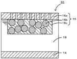
本発明の非水電解質ヨウ素電池の形状は、特に限定されないが、例えばコイン型、ボタン型、シート型、積層型、円筒型、偏平型、角型などが挙げられる。また、電気自動車等に用いる大型のものなどに適用してもよい。図1は、本発明の非水電解質ヨウ素電池の一例を模式的に示す説明図である。この非水電解質ヨウ素電池10は、リチウム金属箔からなる負極14と正極16とをイオン伝導媒体18を介して対向して配置したものである。このうち、正極16は、導電材16bやバインダ16cを混合したあと白金メッシュなどの集電体16aにプレス成形して作製されている。また、イオン伝導媒体18は、リチウムパークロレート等のリチウム塩のほかにヨウ素を含む非水系電解液である。
The shape of the nonaqueous electrolyte iodine battery of the present invention is not particularly limited, and examples thereof include a coin type, a button type, a sheet type, a laminated type, a cylindrical type, a flat type, and a square type. Moreover, you may apply to the large sized thing etc. which are used for an electric vehicle etc. FIG. 1 is an explanatory view schematically showing an example of the nonaqueous electrolyte iodine battery of the present invention. In this nonaqueous
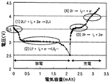
本発明の非水電解質ヨウ素電池の使用方法は、ヨウ素とリチウムイオンとの2電子反応の範囲で充放電を行うものである。こうすれば、リチウムイオンとヨウ素とを含む電解質を用いたものにおいてサイクル特性をより高めることができる。この理由は明らかではないが、以下のように推察される。例えば、金属リチウムを負極活物質とし、ヨウ素を正極活物質とした場合には非水電解質ヨウ素電池の充放電反応は図2のように進行する。図2は、金属リチウムとヨウ素との電気化学反応の一例を示す説明図である。放電時には、まず、式(1)に示すように、ヨウ素分子に対して2電子が関与してLiIを生成する反応が生じる。さらに放電を続けると、式(2)に示すように、ヨウ素分子に対して1電子が関与してリチウムイオンとヨウ素分子ラジカルとからなるLi+[I2 -・]を生成する反応が生じる。一方、充電時には、まず、式(3)に示すように、ヨウ素分子に対して2電子が関与してLiIを分解する反応が生じる。さらに充電を続けると、式(4)に示すように、ヨウ素分子に対して1電子が関与して、LiIを分解する反応が生じる。ここで、ヨウ素分子に対して2電子が関与する2電子反応である式(1)と式(3)の反応は可逆反応の関係にある。一方、ヨウ素分子に対して1電子が関与する1電子反応である式(2)と式(4)の反応は、可逆反応の関係にない。また、式(2)の反応で生じるLi+[I2 -・]や式(4)の反応で生じるヨウ素ラジカル[I2 -・]は反応性が高く、イオン伝導媒体の成分などと反応して、本発明の非水電解質ヨウ素電池の使用範囲では分解できない副生成物を生じやすい。このため、1電子反応が生じると充放電に際して不可逆容量が増加することがある。本発明の非水電解質ヨウ素電池の使用方法では、ヨウ素とリチウムイオンとの2電子反応の範囲で充放電を行うため、このような不可逆容量の増加を抑制可能であり、サイクル特性をより高めることができるものと推察される。なお、式(2)の反応で生じたLi+[I2 -・]は、基本的にはLi+と反応してLiIを生じると考えられる。ここで、ヨウ素とリチウムイオンとの2電子反応の範囲とは、上述の式(1)及び式(3)により充放電反応が生じるような範囲である。ヨウ素とリチウムイオンとの2電子反応の範囲は、主に2電子反応が生じるような範囲であればよいが、2電子反応のみが生じるような範囲としてもよい。このようなヨウ素とリチウムイオンとの2電子反応の範囲は、充電容量及び放電容量の範囲のような容量範囲としてもよい。例えば、2電子反応が生じるような容量の範囲を経験的に求め、その範囲で充放電を行うものとしてもよい。また、充電電位及び放電電位の範囲のような電位範囲としてもよい。例えば、2電子反応が生じるような電位の範囲を経験的に求め、その範囲で充放電を行うものとしてもよい。 The method of using the nonaqueous electrolyte iodine battery of the present invention performs charging / discharging within the range of two-electron reaction between iodine and lithium ions. By doing so, the cycle characteristics can be further improved in the case of using an electrolyte containing lithium ions and iodine. The reason for this is not clear, but is presumed as follows. For example, when metallic lithium is used as the negative electrode active material and iodine is used as the positive electrode active material, the charge / discharge reaction of the nonaqueous electrolyte iodine battery proceeds as shown in FIG. FIG. 2 is an explanatory diagram showing an example of an electrochemical reaction between metallic lithium and iodine. At the time of discharge, first, as shown in Formula (1), a reaction occurs in which two electrons are involved in iodine molecules and LiI is generated. Continuing to discharge, as shown in equation (2), Li + consists of a lithium ion and iodine molecule radicals involved one electron relative to molecular iodine - a reaction which generates a [I 2 ·] is generated. On the other hand, at the time of charging, first, as shown in Formula (3), a reaction occurs in which two electrons are involved in iodine molecules and LiI is decomposed. When the charging is further continued, as shown in the formula (4), one electron is involved in the iodine molecule and a reaction for decomposing LiI occurs. Here, the reaction of Formula (1) and Formula (3), which is a two-electron reaction involving two electrons with respect to iodine molecules, has a reversible reaction relationship. On the other hand, the reactions of formula (2) and formula (4), which are one-electron reactions involving one electron with respect to iodine molecules, are not in a reversible reaction relationship. Further, Equation (2) Li + occurs by the reaction of [I 2 - ·] or the formula (4) Iodine radicals produced by reaction of [I 2 - ·] is highly reactive, reacts with some components of the ion-conducting medium Thus, a by-product that cannot be decomposed easily in the use range of the nonaqueous electrolyte iodine battery of the present invention is likely to be generated. For this reason, when a one-electron reaction occurs, the irreversible capacity may increase during charging and discharging. In the method of using the nonaqueous electrolyte iodine battery of the present invention, charging and discharging are performed within the range of two-electron reaction between iodine and lithium ions, so that such increase in irreversible capacity can be suppressed and cycle characteristics can be further improved. It is presumed that In addition, it is considered that Li + [I 2 − ·] generated by the reaction of the formula (2) basically reacts with Li + to generate LiI. Here, the range of the two-electron reaction between iodine and lithium ions is a range in which a charge / discharge reaction occurs according to the above formulas (1) and (3). The range of the two-electron reaction between iodine and lithium ions may be a range in which a two-electron reaction mainly occurs, but may be a range in which only a two-electron reaction occurs. The range of such a two-electron reaction between iodine and lithium ions may be a capacity range such as a range of charge capacity and discharge capacity. For example, a capacity range in which a two-electron reaction occurs may be obtained empirically, and charging / discharging may be performed within that range. Further, a potential range such as a range of a charging potential and a discharging potential may be used. For example, a potential range where a two-electron reaction occurs may be obtained empirically, and charging / discharging may be performed within that range.
本発明の非水電解質ヨウ素電池の使用方法は、ヨウ素とリチウムイオンとの2電子反応の範囲で充放電を行えばよいが、サイクルの初期から2電子反応の範囲で充放電を行うことが好ましく、初回の充放電から2電子反応の範囲で充放電行うことがより好ましい。こうすれば、サイクル特性をより高めることができるからである。なお、2電子反応の範囲で充放電をするものであれば、例えば、充放電の初期サイクルや途中のサイクルで2電子反応の範囲よりも広い範囲(あるいは2電子反応の範囲とは異なる範囲)で充放電を行ってもよい。 The method of using the nonaqueous electrolyte iodine battery of the present invention may be charged / discharged in the range of two-electron reaction between iodine and lithium ions, but is preferably charged / discharged in the range of two-electron reaction from the beginning of the cycle. It is more preferable to perform charge / discharge within the range of the two-electron reaction from the initial charge / discharge. This is because the cycle characteristics can be further improved. In addition, if charging / discharging is performed in the range of two-electron reaction, for example, a range wider than the range of two-electron reaction in the initial cycle of charge / discharge or an intermediate cycle (or a range different from the range of two-electron reaction). Charging / discharging may be performed.
本発明の非水電解質ヨウ素電池の使用方法は、正極の電位がリチウム基準で3.25Vを下回らないように放電を行い、正極の電位がリチウム基準で3.75Vを上回らないように充電を行うものとしてもよい。こうすれば、より容易に2電子反応の範囲で充放電を行うことができるからである。このうち、正極の電位がリチウム基準で3.3Vを下回らないように放電を行い、正極の電位がリチウム基準で3.7Vを上回らないように充電を行うものとすることが好ましく、正極の電位がリチウム基準で3.35Vを下回らないように放電を行い、正極の電位がリチウム基準で3.65Vを上回らないように充電を行うものとすることがより好ましい。充電電位が低く、放電電位が高いほど、2電子反応が支配的となり、1電子反応による不可逆容量などをより抑制して、サイクル特性をより高めることができると考えられるからである。なお、充電電位を低く、放電電位を高くすると、容量が減少することがあるため、容量とサイクル特性との両面から電位範囲を設定することが好ましい。このような電位範囲で行う充放電に際しては、一定の電気量を放電し、その後一定の電気量を充電する定容量充放電や、一定の電圧まで定電流で放電し、一定の電圧まで定電流で充電する定電流充放電などを選択することができる。ここで、本発明の非水電解質ヨウ素電池において、負極に金属リチウムを用いた場合などには、作動電圧を3.25V以上3.75V以下の範囲とすれば、正極の電位がリチウム基準で3.25Vを下回らないように放電を行い、正極の電位がリチウム基準で3.75Vを上回らないように充電を行うことができる。このため、本発明の非水電解質ヨウ素電池の使用方法は、作動電圧を3.25V以上3.75V以下の範囲として充放電を行うものとしてもよい。 The method of using the nonaqueous electrolyte iodine battery of the present invention performs discharging so that the potential of the positive electrode does not fall below 3.25 V on the basis of lithium, and performs charging so that the potential of the positive electrode does not exceed 3.75 V on the basis of lithium. It may be a thing. This is because charging and discharging can be performed more easily in the range of the two-electron reaction. Among these, it is preferable to perform discharge so that the potential of the positive electrode does not fall below 3.3 V on the basis of lithium, and to charge so that the potential of the positive electrode does not exceed 3.7 V on the basis of lithium. More preferably, the battery is discharged so that it does not fall below 3.35V on the basis of lithium, and is charged so that the potential of the positive electrode does not exceed 3.65V on the basis of lithium. This is because, as the charging potential is lower and the discharging potential is higher, the two-electron reaction is dominant, and it is considered that the irreversible capacity due to the one-electron reaction is further suppressed and the cycle characteristics can be further improved. Note that when the charging potential is low and the discharging potential is high, the capacity may decrease. Therefore, it is preferable to set the potential range from both aspects of capacity and cycle characteristics. When charging / discharging in such a potential range, a certain amount of electricity is discharged, and then a constant capacity charging / discharging to charge a certain amount of electricity, or a constant current to a constant voltage, and a constant current to a certain voltage. The constant current charging / discharging to be charged can be selected. Here, in the nonaqueous electrolyte iodine battery of the present invention, when metallic lithium is used for the negative electrode, the potential of the positive electrode is 3 with respect to lithium if the operating voltage is in the range of 3.25 V to 3.75 V. The battery can be discharged so that it does not fall below .25 V, and charged so that the potential of the positive electrode does not exceed 3.75 V on the basis of lithium. For this reason, the usage method of the nonaqueous electrolyte iodine battery of this invention is good also as what performs charging / discharging by setting the operating voltage as the range of 3.25V or more and 3.75V or less.
なお、本発明は上述した実施形態に何ら限定されることはなく、本発明の技術的範囲に属する限り種々の態様で実施し得ることはいうまでもない。 It should be noted that the present invention is not limited to the above-described embodiment, and it goes without saying that the present invention can be implemented in various modes as long as it belongs to the technical scope of the present invention.
以下には、本発明の非水電解質ヨウ素電池の使用方法について具体的に説明する。 Below, the usage method of the nonaqueous electrolyte iodine battery of this invention is demonstrated concretely.
(1)評価セルの作製
[実験例1]
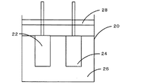
正極は次のようにして作製した。まず、導電材としてのケッチェンブラック(三菱化学製ECP−6000)146mgと、結着材としてのテフロンバインダー(ダイキン工業製、テフロンは登録商標)12mgと、酸化還元触媒としての電解二酸化マンガン(三井鉱山製)10mgとを乾式で乳鉢を用いて練り合わせてシート状の正極部材を得た。この正極部材5mgをPtメッシュ(ニラコ製)に圧着して長さ20mm、幅10mmの正極とした。また、負極には直径10mm、厚さ0.4mmの金属リチウム(本城金属製)を用いた。イオン伝導媒体としての電解液は以下のように調製した。まず、エチレンカーボネート(EC)とジエチルカーボネート(DEC)を3:7の混合比(体積比)で混合したもの(EC/DEC)に1mol/Lのリチウムパークロレートを溶解した溶液(富山薬品工業製)12mLを用意した。これに、0.01mol/Lのヨウ素(アルドリッチ製)を溶解させた。このようにして得られた正極、負極、電解液を用いて、次のように評価セルを作製した。まず、図3に示すように、正極22及び負極24をアルゴン雰囲気下のグローブボックス内でビーカーセル20にセットし、電解液26を15ml注入した。次に、ビーカーセル20の開放部にプラスチック製の蓋28を取り付け、ビーカーセル20を密閉して評価セルとした。なお、ビーカーセル内の空間にはアルゴンが充填されている。また、ビーカーセル20の容量は約30mlである。このようにして得られた評価セルを実験例1とした。
(1) Production of evaluation cell [Experimental example 1]
The positive electrode was produced as follows. First, 146 mg of ketjen black (ECP-6000 manufactured by Mitsubishi Chemical) as a conductive material, 12 mg of Teflon binder (made by Daikin Industries, Teflon is a registered trademark) as a binder, and electrolytic manganese dioxide (Mitsui) as a redox catalyst (Mine) 10 mg was dry-kneaded using a mortar to obtain a sheet-like positive electrode member. 5 mg of this positive electrode member was pressure-bonded to a Pt mesh (manufactured by Niraco) to obtain a positive electrode having a length of 20 mm and a width of 10 mm. Further, metallic lithium (manufactured by Honjo Metal) having a diameter of 10 mm and a thickness of 0.4 mm was used for the negative electrode. An electrolytic solution as an ion conducting medium was prepared as follows. First, a solution of 1 mol / L lithium perchlorate dissolved in a mixture (EC / DEC) of ethylene carbonate (EC) and diethyl carbonate (DEC) in a mixing ratio (volume ratio) of 3: 7 (manufactured by Toyama Pharmaceutical Co., Ltd.) ) 12 mL was prepared. To this, 0.01 mol / L iodine (manufactured by Aldrich) was dissolved. Using the positive electrode, negative electrode, and electrolytic solution thus obtained, an evaluation cell was prepared as follows. First, as shown in FIG. 3, the
[実験例2,3]
電解液の調製に際し、ヨウ素を0.02mol/L溶解させた以外は実験例1と同様の工程を経て実験例2の評価セルを作製した。また、電解液の調製に際し、ヨウ素を0.06mol/L溶解させた以外は実験例1と同様の工程を経て実験例3の評価セルを作製した。
[Experimental Examples 2 and 3]
In preparing the electrolytic solution, an evaluation cell of Experimental Example 2 was produced through the same steps as Experimental Example 1 except that 0.02 mol / L of iodine was dissolved. Moreover, in preparing the electrolytic solution, an evaluation cell of Experimental Example 3 was manufactured through the same steps as Experimental Example 1 except that 0.06 mol / L of iodine was dissolved.
[実験例4]
電解液の調製に際して、3−メトキシプロピオニトリルに1mol/Lのリチウムトリフルオロメタンスルホニルイミドを溶解した溶液12mLを用意した。これに、0.08mol/Lのヨウ素を溶解させた。この電解液の調製以外は実験例1と同様の工程を経て実験例4の評価セルを作製した。
[Experimental Example 4]
In preparing the electrolytic solution, 12 mL of a solution in which 1 mol / L lithium trifluoromethanesulfonylimide was dissolved in 3-methoxypropionitrile was prepared. 0.08 mol / L iodine was dissolved in this. An evaluation cell of Experimental Example 4 was produced through the same steps as in Experimental Example 1 except for the preparation of the electrolytic solution.
[実験例5]
正極部材の原料として、導電材としての黒鉛(大阪ガス製、MCMB)90mgと、結着材としてのテフロンバインダー10mgとを用いた以外は、実験例2と同様の工程を経て実験例5の評価セルを作製した。
[Experimental Example 5]
Evaluation of Experimental Example 5 through the same steps as Experimental Example 2 except that 90 mg of graphite (MCMB, manufactured by Osaka Gas Co., Ltd.) and 10 mg of Teflon binder as a binder were used as the raw material for the positive electrode member. A cell was produced.
表1に、上述した実験例1〜5の電解液中のヨウ素濃度、電解液の種類及び正極の種類を示した。 Table 1 shows the iodine concentration, the type of the electrolytic solution, and the type of the positive electrode in the electrolytic solutions of Experimental Examples 1 to 5 described above.
(2)充放電試験
組み立てた評価セルを北斗電工製の充放電装置(型名HJ1001SM8A)に接続し、測定温度を25℃とし、充放電試験を行った。
(2) Charge / Discharge Test The assembled evaluation cell was connected to a charge / discharge device (model name HJ1001SM8A) manufactured by Hokuto Denko, and the measurement temperature was set to 25 ° C. to perform a charge / discharge test.
(2−1)充放電反応のヨウ素濃度依存性の検討
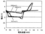
電解液中のヨウ素濃度の異なる実験例1〜3の評価セルを用いて、充放電試験を行った。具体的には、まず、正極と負極との間で0.025mA(正極材料あたり100mA/g)の電流で2mAhまで放電した。その後、0.025mAの電流で4.3V(又は2mAh)まで充電した。このときの充放電曲線を図4に示した。
(2-1) Examination of dependence of charge / discharge reaction on iodine concentration A charge / discharge test was conducted using the evaluation cells of Experimental Examples 1 to 3 having different iodine concentrations in the electrolytic solution. Specifically, first, discharging was performed to 2 mAh at a current of 0.025 mA (100 mA / g per positive electrode material) between the positive electrode and the negative electrode. Thereafter, the battery was charged to 4.3 V (or 2 mAh) at a current of 0.025 mA. The charge / discharge curve at this time is shown in FIG.
図4は、実験例1〜3の充放電曲線である。ヨウ素濃度が0.01mol/Lの実験例1では、放電開始から約0.2mAhまではリチウム基準で3.3〜3.5Vの間に平坦部が確認され、この範囲で2電子反応が生じることが分かった。また、約0.3mAhから1.5mAhまでの放電ではリチウム基準で約3.0V付近に平坦部が確認され、この範囲で1電子反応が生じることが分かった。さらに、約1.5mAhから2mAhまでの放電では若干の電圧低下が確認された。また、続く充電では、充電開始から約0.5mAhまでの充電では、リチウム基準で約3.6V付近に平坦部が確認され、この範囲で2電子反応が生じることが分かった。その後は、電圧が上昇し続け、この範囲で1電子反応が生じることが分かった。また、4.3Vまでの充電で得られた容量は1.3mAh程度であり、放電容量に対して7割程度の充電容量しか得られないことが分かった。ヨウ素濃度が0.02mol/Lの実験例2では、放電開始から約0.4mAhまではリチウム基準で3.3〜3.5Vの間に平坦部が確認され、この範囲で2電子反応が生じることが分かった。また、約0.6mAhから2.0mAhまでの放電ではリチウム基準で約3.0V付近に平坦部が確認され、この範囲で1電子反応が生じることが分かった。また、続く充電では、充電開始から約1mAhまでの充電では、リチウム基準で約3.6V付近に平坦部が確認され、この範囲で2電子反応が生じることが分かった。その後は、電圧が上昇し続け、この範囲で1電子反応が生じることが分かった。また、4.3Vまでの充電で得られた容量は1.4mAh程度であり、放電容量に対して7割程度の充電容量しか得られないことが分かった。ヨウ素濃度が0.06mol/Lの実験例3では、放電開始から放電容量2mAhまでリチウム基準で3.3〜3.5Vの間に平坦部が確認され、放電終了まで2電子反応が生じることが分かった。また、続く充電では、充電開始から充電容量2mAhまでリチウム基準で約3.6V付近に平坦部が確認され、充電開始から2mAhまでの充電の間2電子反応が生じることが分かった。 FIG. 4 is a charge / discharge curve of Experimental Examples 1 to 3. In Experimental Example 1 where the iodine concentration is 0.01 mol / L, a flat portion is confirmed between 3.3 and 3.5 V on the basis of lithium from the start of discharge to about 0.2 mAh, and a two-electron reaction occurs within this range. I understood that. Further, in the discharge from about 0.3 mAh to 1.5 mAh, a flat portion was confirmed in the vicinity of about 3.0 V with respect to lithium, and it was found that a one-electron reaction occurred within this range. Furthermore, a slight voltage drop was confirmed in the discharge from about 1.5 mAh to 2 mAh. In the subsequent charging, a flat portion was confirmed near about 3.6 V on the basis of lithium in charging from the start of charging to about 0.5 mAh, and it was found that a two-electron reaction occurred within this range. Thereafter, the voltage continued to rise, and it was found that a one-electron reaction occurred within this range. Further, it was found that the capacity obtained by charging up to 4.3 V was about 1.3 mAh, and only about 70% of the charge capacity was obtained with respect to the discharge capacity. In Experimental Example 2 where the iodine concentration is 0.02 mol / L, a flat portion is confirmed between 3.3 and 3.5 V on the basis of lithium from the start of discharge to about 0.4 mAh, and a two-electron reaction occurs in this range. I understood that. Further, in the discharge from about 0.6 mAh to 2.0 mAh, a flat portion was confirmed in the vicinity of about 3.0 V with respect to lithium, and it was found that a one-electron reaction occurred within this range. Further, in the subsequent charging, in the charging from the start of charging to about 1 mAh, a flat portion was confirmed near about 3.6 V on the basis of lithium, and it was found that a two-electron reaction occurred within this range. Thereafter, the voltage continued to rise, and it was found that a one-electron reaction occurred within this range. Further, it was found that the capacity obtained by charging up to 4.3 V was about 1.4 mAh, and only about 70% of the charge capacity was obtained with respect to the discharge capacity. In Experimental Example 3 where the iodine concentration is 0.06 mol / L, a flat portion is confirmed between 3.3 to 3.5 V on the basis of lithium from the start of discharge to a discharge capacity of 2 mAh, and a two-electron reaction occurs until the end of discharge. I understood. Further, in the subsequent charging, a flat portion was confirmed in the vicinity of about 3.6 V from the start of charging to the charging capacity of 2 mAh, and it was found that a two-electron reaction occurred during the charging from the start of charging to 2 mAh.
以上より、2電子反応により得られる容量範囲はヨウ素濃度が0.01mol/Lのものより0.02mol/Lのものが広く、0.06mol/Lのものがより広いことが分かった。このことから、充放電特性は、ヨウ素濃度に対する依存性があり、ヨウ素濃度が高いほど2電子反応により得られる容量が大きいものと推察された。そして、充放電に際して2電子反応のみを利用すると、放電容量に対して十分な充電容量を得ることができることが分かった。また、低い充電電位で充電を行うことができ、高い放電電位を得ることができ、充電電位と放電電位の差が小さく、クーロン効率が高いことが分かった。 From the above, it was found that the capacity range obtained by the two-electron reaction was wider for 0.02 mol / L than that for 0.01 mol / L and wider for 0.06 mol / L. From this, it was speculated that the charge / discharge characteristics depend on the iodine concentration, and that the capacity obtained by the two-electron reaction increases as the iodine concentration increases. And it turned out that sufficient charge capacity with respect to discharge capacity can be obtained if only two-electron reaction is utilized in charging and discharging. It was also found that charging can be performed at a low charging potential, a high discharging potential can be obtained, the difference between the charging potential and the discharging potential is small, and the coulomb efficiency is high.
(2−2)充放電反応とサイクル特性の関係の検討
2電子反応のみを用いた場合と、それ以外の場合とのサイクル特性を比較するため、実験例2,3の評価セルを用いて、充放電試験を行った。具体的には、正極と負極との間で0.025mAの電流で2mAhまで放電し、0.025mAの電流で4.3V(又は2mAh)まで充電し、この放電と充電を1サイクルとして放電と充電を繰り返した。
(2-2) Examination of relationship between charge / discharge reaction and cycle characteristics In order to compare the cycle characteristics between the case where only the two-electron reaction is used and the other cases, the evaluation cells of Experimental Examples 2 and 3 are used. A charge / discharge test was conducted. Specifically, the battery is discharged at a current of 0.025 mA to 2 mAh between the positive electrode and the negative electrode, charged to 4.3 V (or 2 mAh) at a current of 0.025 mA, and this discharge and charge are discharged as one cycle. Repeated charging.
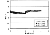
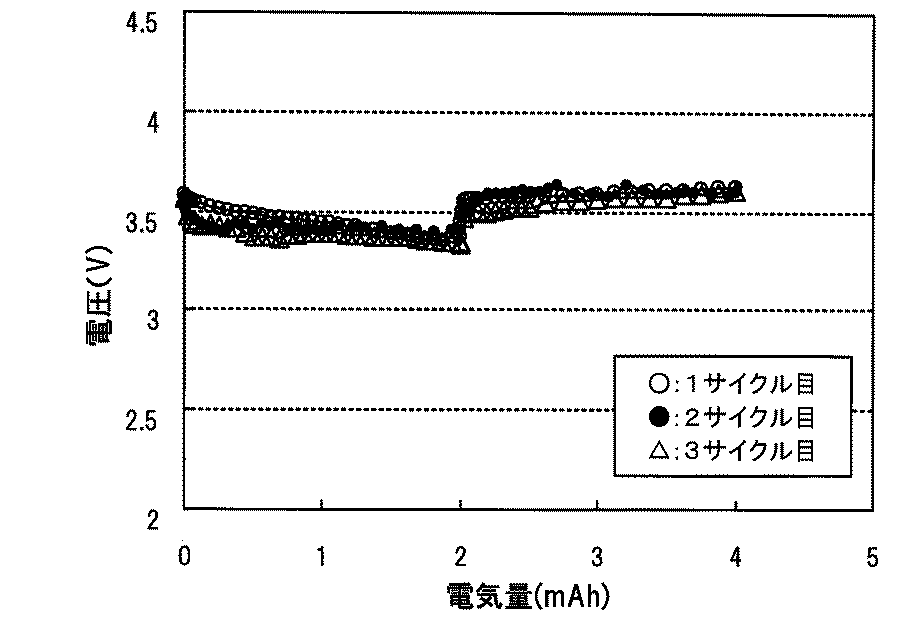
図5は、実験例3の3サイクル目までの充放電曲線である。図5より、2電子反応の範囲で充放電を行ったものでは、放電と充電を繰り返しても、放電容量に対して十分な充電容量まで充電を行うことができることが分かった。 FIG. 5 is a charge / discharge curve up to the third cycle of Experimental Example 3. From FIG. 5, it was found that in the case where charge / discharge was performed in the range of the two-electron reaction, it was possible to charge to a sufficient charge capacity with respect to the discharge capacity even if the discharge and charge were repeated.
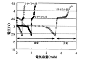
図6は、実験例2の3サイクル目までの充放電曲線である。図6より、2電子反応の範囲より広い範囲で充放電を行ったものでは、放電容量に対して7割程度の充電容量までしか充電を行うことができないことが分かった。なお、実験例2でも、2電子反応の範囲で充放電を行えば、サイクル特性を高めることができるものと推察された。また、1サイクル目では、放電初期及び充電初期で平坦部が確認され2電子反応が生じるが、サイクルを繰り返すと、平坦部が少なくなることが分かった。このことから、サイクルの初回から2電子反応の範囲で充放電を行えば、サイクル特性をより高めることができ好ましいと推察された。また、サイクルを繰り返すと放電電圧が低下し、充電電圧が上昇する傾向にあることが分かった。放電電圧が低下し充電電圧が上昇する理由は明らかではないが、2電子反応以外の反応による生成物が正極上に堆積するなどし、この生成物がヨウ素の酸化還元反応を阻害したためと推察された。なお、実験例2のものでは、2電子反応により得られる容量は少ないものの、2電子反応の範囲で充放電を行えば、サイクル特性を高めることができると推察された。 FIG. 6 is a charge / discharge curve up to the third cycle of Experimental Example 2. From FIG. 6, it was found that when charging / discharging was performed in a range wider than the range of the two-electron reaction, charging could be performed only to a charging capacity of about 70% of the discharging capacity. In Experimental Example 2, it was presumed that the cycle characteristics could be improved by charging and discharging within the range of the two-electron reaction. Further, in the first cycle, a flat portion was confirmed in the initial stage of discharge and in the initial stage of charging, and a two-electron reaction occurred. However, it was found that the flat portion decreased when the cycle was repeated. From this, it was speculated that it is preferable to perform charge / discharge within the range of the two-electron reaction from the first cycle, since the cycle characteristics can be further improved. Further, it was found that when the cycle was repeated, the discharge voltage decreased and the charge voltage tended to increase. The reason why the discharge voltage decreases and the charge voltage increases is not clear, but it is presumed that this product hindered the redox reaction of iodine, for example, because a product other than the two-electron reaction was deposited on the positive electrode. It was. In addition, although the capacity | capacitance obtained by a two-electron reaction was little in the thing of Experimental example 2, if it charged / discharged in the range of a two-electron reaction, it was guessed that cycling characteristics could be improved.
図7は、実験例2,3の8サイクル目までの充電容量を示すグラフである。図7より、2電子反応の範囲で充放電を行った実験例3では、2mAhの放電容量に対して2mAhの充電容量を維持できるのに対し、2電子反応の範囲より広い範囲で充放電を行った実験例2では、2mAhの放電容量に対して1サイクル目から1.5mAhの充電容量までしか充電を行うことができず、サイクルを繰り返すと、充電可能な充電容量がより低下することが分かった。 FIG. 7 is a graph showing the charge capacity up to the eighth cycle of Experimental Examples 2 and 3. As shown in FIG. 7, in Experimental Example 3 in which charging / discharging was performed in the range of two-electron reaction, the charge capacity of 2 mAh was maintained with respect to the discharge capacity of 2 mAh, whereas charging / discharging was performed in a range wider than the range of two-electron reaction. In Experimental Example 2 that was performed, only a charge capacity of 1.5 mAh can be charged from the first cycle to a discharge capacity of 2 mAh. If the cycle is repeated, the chargeable charge capacity may be further reduced. I understood.
(2−3)充放電反応と電解液の関係の検討
上述した実験例1〜3とは電解液の種類が異なる実験例4の評価セルを用いて、充放電試験を行った。具体的には、まず、正極と負極との間で0.025mAの電流で8mAhまで放電した。その後、0.025mAの電流で8mAhまで充電した。
(2-3) Examination of relationship between charge / discharge reaction and electrolytic solution A charge / discharge test was performed using the evaluation cell of Experimental Example 4 in which the type of electrolytic solution is different from those of Experimental Examples 1 to 3 described above. Specifically, first, discharge was performed to 8 mAh at a current of 0.025 mA between the positive electrode and the negative electrode. Thereafter, the battery was charged to 8 mAh with a current of 0.025 mA.
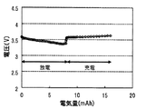
図8は、実験例4の充放電曲線である。この実験例4では、ヨウ素濃度が0.08mol/Lであり、放電開始から放電容量8mAhまでリチウム基準で3.3〜3.6Vの電位範囲の平坦部が確認され、放電終了まで、2電子反応が生じることが分かった。また、続く充電では、充電開始から充電容量8mAhまでリチウム基準で約3.6Vの電位範囲の平坦部が確認され、充電終了まで2電子反応が生じることが分かった。 FIG. 8 is a charge / discharge curve of Experimental Example 4. In Experimental Example 4, the iodine concentration was 0.08 mol / L, and a flat portion having a potential range of 3.3 to 3.6 V on the lithium basis from the start of discharge to the discharge capacity of 8 mAh was confirmed. It was found that a reaction occurred. In the subsequent charging, a flat portion having a potential range of about 3.6 V on the basis of lithium was confirmed from the start of charging to a charging capacity of 8 mAh, and it was found that a two-electron reaction occurred until the end of charging.
このように、電解液を変えても2電子反応の範囲で充放電を行うことが可能であり、2電子反応の範囲で充放電を行うと、放電容量に対して十分な充電容量を得ることができることが分かった。また、充電電位と放電電位の差が小さく、クーロン効率が高めることができることが分かった。 Thus, even if the electrolyte is changed, charging / discharging can be performed within the range of two-electron reaction, and when charging / discharging is performed within the range of two-electron reaction, sufficient charge capacity can be obtained with respect to the discharge capacity I found out that It was also found that the difference between the charging potential and the discharging potential was small and the coulomb efficiency could be increased.
(2−4)充放電電圧の検討
実験例3の評価セルを用いて、正極と負極との間で0.025mAの電流で3.25Vまで放電し、0.025mAの電流で3.75Vまで充電し、この放電と充電を1サイクルとして放電と充電を繰り返した。
(2-4) Examination of charging / discharging voltage Using the evaluation cell of Experimental Example 3, the positive and negative electrodes were discharged at a current of 0.025 mA to 3.25 V, and at a current of 0.025 mA to 3.75 V. The battery was charged, and discharging and charging were repeated with this discharging and charging as one cycle.
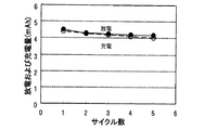
図9は、実験例3の5サイクル目までの放電容量および充電容量を示すグラフである。各サイクルで、放電容量より充電容量が若干低いものの、ほぼ同等の容量が得られることが分かった。このことから、例えば、3.25V以上3.75V以下の作動電圧範囲は、2電子反応の範囲と同等であることが分かった。 FIG. 9 is a graph showing the discharge capacity and the charge capacity up to the fifth cycle of Experimental Example 3. It was found that in each cycle, the charge capacity was slightly lower than the discharge capacity, but almost the same capacity was obtained. From this, it was found that, for example, an operating voltage range of 3.25 V or more and 3.75 V or less is equivalent to a two-electron reaction range.
(2−5)酸化還元触媒の影響の検討
電解二酸化マンガン(酸化還元触媒)を含まない正極を用いた実験例5の評価セルを用いて、正極と負極との間で0.025mAの電流で2.4Vまで放電し、0.025mAの電流で4.3Vまで充電し、この放電と充電を1サイクルとして放電と充電を繰り返した。
(2-5) Examination of influence of oxidation-reduction catalyst Using the evaluation cell of Experimental Example 5 using a positive electrode not containing electrolytic manganese dioxide (oxidation-reduction catalyst), at a current of 0.025 mA between the positive electrode and the negative electrode The battery was discharged to 2.4 V, charged to 4.3 V with a current of 0.025 mA, and discharging and charging were repeated with this discharging and charging as one cycle.
図10は、実験例5の3サイクル目までの充放電曲線である。図10より、実験例5では、放電と充電を繰り返すと、充電容量だけでなく放電容量も低下することが分かった。これに対し、電解二酸化マンガンを含む正極を用いた実験例1〜4の評価セルを用いた充放電では、放電容量の低下は生じなかった。このことから、電解二酸化マンガンはヨウ素の酸化還元触媒として働き、放電容量および充電容量を高める効果があるものと推察された。 FIG. 10 is a charge / discharge curve up to the third cycle of Experimental Example 5. From FIG. 10, it was found that in Experimental Example 5, when discharging and charging were repeated, not only the charging capacity but also the discharging capacity was reduced. On the other hand, in the charge / discharge using the evaluation cells of Experimental Examples 1 to 4 using the positive electrode containing electrolytic manganese dioxide, the discharge capacity did not decrease. From this, it was speculated that electrolytic manganese dioxide acts as an oxidation-reduction catalyst for iodine and has an effect of increasing the discharge capacity and the charge capacity.
10 非水電解質ヨウ素電池、14 負極、16 正極、16a 集電体、16b 導電材、16c バインダ、18 イオン伝導媒体、20 ビーカーセル、22 正極、24 負極、26 電解液、28 蓋。 10 non-aqueous electrolyte iodine battery, 14 negative electrode, 16 positive electrode, 16a current collector, 16b conductive material, 16c binder, 18 ion conductive medium, 20 beaker cell, 22 positive electrode, 24 negative electrode, 26 electrolyte, 28 lid.
Claims (3)
ヨウ素を正極活物質とする正極と、
前記正極と前記負極との間に介在し、リチウムイオンとヨウ素とを含みリチウムイオンを伝導するイオン伝導媒体とを備えた非水電解質ヨウ素電池の使用方法であって、
ヨウ素とリチウムイオンとの電気化学的な2電子反応の範囲で充放電を行う、
非水電解質ヨウ素電池の使用方法。 A negative electrode using a material that releases lithium ions as a negative electrode active material;
A positive electrode using iodine as a positive electrode active material;
A method of using a non-aqueous electrolyte iodine battery comprising an ion conductive medium interposed between the positive electrode and the negative electrode and containing lithium ions and iodine and conducting lithium ions,
Charge and discharge within the range of electrochemical two-electron reaction between iodine and lithium ions.
How to use non-aqueous electrolyte iodine battery.
請求項1に記載の非水電解質ヨウ素電池の使用方法。 Discharging so that the potential of the positive electrode does not fall below 3.25 V on the basis of lithium, and charging so that the potential of the positive electrode does not exceed 3.75 V on the basis of lithium.
A method of using the nonaqueous electrolyte iodine battery according to claim 1.
請求項1又は2に記載の非水電解質ヨウ素電池の使用方法。 In the non-aqueous electrolyte iodine battery, the ion conduction medium includes 0.02 mol / L or more and a saturation amount of iodine or less.
A method for using the nonaqueous electrolyte iodine battery according to claim 1.
Priority Applications (1)
| Application Number | Priority Date | Filing Date | Title |
|---|---|---|---|
| JP2011013937A JP2012155992A (en) | 2011-01-26 | 2011-01-26 | Method for using nonaqueous electrolyte iodine battery |
Applications Claiming Priority (1)
| Application Number | Priority Date | Filing Date | Title |
|---|---|---|---|
| JP2011013937A JP2012155992A (en) | 2011-01-26 | 2011-01-26 | Method for using nonaqueous electrolyte iodine battery |
Publications (1)
| Publication Number | Publication Date |
|---|---|
| JP2012155992A true JP2012155992A (en) | 2012-08-16 |
Family
ID=46837519
Family Applications (1)
| Application Number | Title | Priority Date | Filing Date |
|---|---|---|---|
| JP2011013937A Pending JP2012155992A (en) | 2011-01-26 | 2011-01-26 | Method for using nonaqueous electrolyte iodine battery |
Country Status (1)
| Country | Link |
|---|---|
| JP (1) | JP2012155992A (en) |
Cited By (2)
| Publication number | Priority date | Publication date | Assignee | Title |
|---|---|---|---|---|
| CN115863614A (en) * | 2021-09-24 | 2023-03-28 | 南京理工大学 | Porous carbon loaded with monatomic nickel, its preparation method and its application in iodine battery |
| CN116264316A (en) * | 2021-12-15 | 2023-06-16 | 香港城市大学 | Organic lithium-iodine battery based on two-electron transfer mechanism and its manufacturing method and application |
-
2011
- 2011-01-26 JP JP2011013937A patent/JP2012155992A/en active Pending
Cited By (2)
| Publication number | Priority date | Publication date | Assignee | Title |
|---|---|---|---|---|
| CN115863614A (en) * | 2021-09-24 | 2023-03-28 | 南京理工大学 | Porous carbon loaded with monatomic nickel, its preparation method and its application in iodine battery |
| CN116264316A (en) * | 2021-12-15 | 2023-06-16 | 香港城市大学 | Organic lithium-iodine battery based on two-electron transfer mechanism and its manufacturing method and application |
Similar Documents
| Publication | Publication Date | Title |
|---|---|---|
| US11551878B2 (en) | Electricity storage device | |
| JP2012209161A (en) | Lithium secondary battery | |
| JP5169181B2 (en) | Non-aqueous electrolyte secondary battery | |
| JP5380826B2 (en) | Lithium ion secondary battery | |
| JP2013145712A (en) | Nonaqueous electrolyte secondary battery | |
| JP5256649B2 (en) | Water-based lithium secondary battery | |
| JP6268833B2 (en) | Non-aqueous electrolyte secondary battery and method for producing non-aqueous electrolyte secondary battery | |
| JP2013114920A (en) | Lithium sulfur battery | |
| JP2012216500A (en) | Lithium secondary battery | |
| JP2014191915A (en) | Electrode for power storage device and power storage device using the same | |
| JP2014096213A (en) | Alkali metal-air secondary battery | |
| JP5633397B2 (en) | Non-aqueous air battery and method for producing non-aqueous air battery | |
| JP5691781B2 (en) | Non-aqueous electrolyte halogen battery | |
| JP4998392B2 (en) | Non-aqueous electrolyte battery | |
| JP5504853B2 (en) | How to use lithium secondary battery | |
| JP6668848B2 (en) | Lithium ion secondary battery | |
| CN105655646A (en) | Lithium ion energy storage element and manufacturing method thereof | |
| JP2014195018A (en) | Electric power storage device | |
| JP2011171072A (en) | Nonaqueous electrolyte air battery | |
| JP2012155992A (en) | Method for using nonaqueous electrolyte iodine battery | |
| JP5676886B2 (en) | Non-aqueous secondary battery positive electrode and non-aqueous secondary battery using the same | |
| JP2009199879A (en) | Lithium gas battery and oxidation/reduction catalyst | |
| JP2014044896A (en) | Nonaqueous electrolyte air battery and its using method | |
| JP5625897B2 (en) | Non-aqueous air battery | |
| JP5929436B2 (en) | Non-aqueous air battery |