JP2012158043A - Printer - Google Patents
Printer Download PDFInfo
- Publication number
- JP2012158043A JP2012158043A JP2011018453A JP2011018453A JP2012158043A JP 2012158043 A JP2012158043 A JP 2012158043A JP 2011018453 A JP2011018453 A JP 2011018453A JP 2011018453 A JP2011018453 A JP 2011018453A JP 2012158043 A JP2012158043 A JP 2012158043A
- Authority
- JP
- Japan
- Prior art keywords
- printer
- casing
- printing medium
- suction cup
- platen roller
- Prior art date
- Legal status (The legal status is an assumption and is not a legal conclusion. Google has not performed a legal analysis and makes no representation as to the accuracy of the status listed.)
- Pending
Links
Images

Landscapes
- Accessory Devices And Overall Control Thereof (AREA)
Abstract
【課題】人や物がぶつかった場合や地震発生時も設置箇所からの落下を防止できるとともに、固定のために作業台や机に孔をあける必要が無く、設置場所の変更も簡単なプリンタを提供する。
【解決手段】少なくとも底面と側面とを有する筐体と、印字媒体を供給する印字媒体供給部と、プラテンローラとサーマルヘッドとで該印字媒体を押圧挟持しながら前記プラテンローラの回転駆動により印字媒体を搬送して情報を記録する印字部と、を含むプリンタであって、前記筐体の一または複数箇所に、吸着面を筐体外方へ向けた吸盤を取り付けておく。
【選択図】図1[PROBLEMS] To prevent a fall from an installation location even when a person or an object collides or an earthquake occurs, and it is not necessary to make a hole in a workbench or desk for fixing, and a printer that can be easily changed is installed. provide.
A printing medium driven by rotation of the platen roller while pressing and holding the printing medium by a casing having at least a bottom surface and a side surface, a printing medium supply unit for supplying the printing medium, a platen roller and a thermal head. And a printing unit for recording information, and a suction cup with a suction surface facing the outside of the casing is attached to one or a plurality of locations of the casing.
[Selection] Figure 1
Description
本発明は、ラベル、タグ、チケットなどの印字媒体に情報を印字して発行するプリンタに関する。 The present invention relates to a printer that prints and issues information on a printing medium such as a label, tag, or ticket.
プリンタは、オフィス、工場、作業場をはじめとして多くの場所に設置され、ラベル、伝票、荷札、明細票、チケット、会員証、リストバンド、カルテなどの印字媒体の印字発行に用いられる。多くの場合、内容が一片ずつ異なる可変情報を印字して発行する際に用いられる。プリンタとしては、熱転写リボンを用いる熱転写方式、サーマル紙を発色させるダイレクトサーマル方式、インクジェット方式、トナー方式等があり、用途に応じて使い分けられて来た。 Printers are installed in many places including offices, factories, and workplaces, and are used for printing and issuing printing media such as labels, slips, tags, statement slips, tickets, membership cards, wristbands, and medical records. In many cases, it is used when printing and issuing variable information whose contents are different one by one. As printers, there are a thermal transfer method using a thermal transfer ribbon, a direct thermal method for coloring thermal paper, an ink jet method, a toner method, and the like.
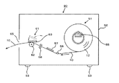
ここで、図3に示すプリンタ90を用い、印字媒体として、長尺帯状の台紙にラベルを一定間隔で仮着したラベル連続体に対し、ラベル一枚毎に異なる情報を印字する例を説明する。図3はプリンタ90の主要部をシンボル化して示した概略側面図である。
Here, an example will be described in which different information is printed for each label on a continuous label body in which labels are temporarily attached to a long belt-like mount at regular intervals as a printing medium using the
プリンタ90は、印字媒体供給部51と印字部61を筐体52内に設けたものである。印字媒体供給部51の供給軸55にはラベルロール12が回転可能に支持されている。ラベルロールはラベル10の連続体を支管に巻回したものである。ラベル10の走行経路に沿って、ガイドバー56、ラベル10の連続体の有無を検知する用紙センサ57、ラベルのインターバルを検出するピッチセンサ58が取り付けられている。その下流の印字部61は、プラテンローラ62と、前記プラテンローラ62とともにラベル10の連続体を押圧保持するサーマルヘッド63で構成される。筐体52には、印字部61の隣接位置に発行口65が設けられる。筐体52の底にはゴム製あるいは合成樹脂製の足53が取付けられ、プリンタ90の重量を支える。足53の底部は滑りやすいことが多い。
The
プラテンローラ62が回転すると、ラベルロール12から巻き出されたラベル10の連続体は、ガイドバー56、用紙センサ57、ピッチセンサ58を経て印字部61に至り、各ラベル10にサーマルヘッド63の発熱走査で文字やバーコード等の画像が印字される。印字が行なわれたラベル10は発行口65から外部に至る。
When the
プリンタ90の設置場所は様々である。必ずしも広い作業台に置いてあるとは限らない。例えば、工場では作業台の隅に設置されていたり、食品工場ではステンレス製の食品加工台の脇に置いてあることもある。ラベル、タグ、チケット等の出力端末であるという性格状、事務所でも机の端に置かれることが多い。また、プリンタ90の設置場所は作業台や机のような床に据え置かれた台とは限らない。床面を自在に移動可能な車輪が付いたキャスタに載せ、ラベル等の発行作業に応じて移動する場合も多々ある。
There are various installation locations of the
プリンタが作業台や机の端に置いてある場合、設置位置の隣は人や物の移動に用いる通路の場合がある。人や物が動く動線に隣接している限り、歩行者の手や肘が触れたり物がぶつかることによる衝撃を受けることがある。衝撃が小さい場合はプリンタ90の向きが変わる程度で済むが、大きな衝撃を受けると台や机からプリンタ90が落下してしまう。この他に自然災害もある。大規模な地震が発生するとプリンタ90が台や机の上を滑り、床面に落下する。また、キャスタに載せて移動する場合、床面が平坦だとは限らない。床の凹凸や段差を乗り越える際の上下動する衝撃でプリンタが落下してしまう。
When the printer is placed at the end of a workbench or desk, there may be a passage used for moving people or objects next to the installation position. As long as the person or object is adjacent to the movement line, the hand or elbow of the pedestrian may be touched or hit by an object. When the impact is small, it is sufficient to change the orientation of the
床に落下したプリンタ90は修理が必要になり、使用者の損失を招く。落下防止の有効な対策としてプリンタを台や机に螺旋留めする等の固定方法があるが、作業台や机に孔をあける必要があり手間がかかる。また、プリンタ90を新機種に更新するたびに孔の位置が変わり、台や机に不必要な孔が増えて美観を損ねるという問題もある。さらに、プリンタ90を一旦固定すると、作業台や机の上のレイアウトを変更しにくくなるという不便さも生じてしまう。
The
そこで、作業台や机に簡単に固定して落下を防止できるとともに、移動も容易で、工場やオフィスのレイアウト変更にも簡単に対応できるプリンタが求められていた。 Therefore, there has been a demand for a printer that can be easily fixed to a workbench or a desk to prevent falling, can be easily moved, and can easily cope with changes in the layout of a factory or office.
本発明は前記のような諸問題に鑑みなされたもので、作業台や机に簡単に固定でき、揺れや振動、衝撃を受けた場合でも落下を防止できるとともに、設置場所の変更も容易なプリンタを提供することを目的とする。 The present invention has been made in view of the above-described problems, and can be easily fixed to a work table or a desk, can be prevented from falling even when subjected to shaking, vibration, or impact, and can be easily changed in installation location. The purpose is to provide.
本発明の第1の発明であるプリンタは、少なくとも底面と側面とを有する筐体と、印字媒体を供給する印字媒体供給部と、プラテンローラとサーマルヘッドとで該印字媒体を押圧挟持しながら前記プラテンローラの回転駆動により印字媒体を搬送して情報を記録する印字部と、を含むプリンタであって前記筐体の一または複数箇所に、吸着面を筐体外方へ向けて吸盤が取り付けてあることを特徴としている。
前記の筐体と吸盤との距離を可変にして調整可能にしておくことが望ましい。
前記の吸盤は筐体から突き出たボルトの先端に取り付け、そのボルトを筐体に設けられた螺子孔と螺合させる。ボルトの回転により筐体と吸盤の距離を調整可能にしておく。
本発明の第2の発明であるプリンタの固定方法は、少なくとも底面と側面とを有する筐体と、印字媒体を供給する印字媒体供給部と、プラテンローラとサーマルヘッドとで該印字媒体を押圧挟持しながら前記プラテンローラの回転駆動により印字媒体を搬送して情報を記録する印字部と、を含むプリンタに、前記筐体の一または複数箇所に、吸着面を筐体外方へ向けて吸盤を取り付け、前記吸盤をプリンタの設置箇所の載置面やプリンタに近接した面の一方または両方に吸着固定することを特徴としている。
The printer according to the first aspect of the present invention includes a casing having at least a bottom surface and a side surface, a print medium supply unit for supplying a print medium, a platen roller, and a thermal head while pressing and holding the print medium. And a printing unit that records information by conveying a printing medium by rotation of a platen roller, and a suction cup is attached to one or a plurality of locations of the casing with the suction surface facing the outside of the casing It is characterized by that.
It is desirable that the distance between the housing and the suction cup be variable and adjustable.
The suction cup is attached to the tip of a bolt protruding from the housing, and the bolt is screwed into a screw hole provided in the housing. The distance between the housing and the suction cup can be adjusted by rotating the bolt.
According to a second aspect of the present invention, there is provided a fixing method for a printer, wherein a casing having at least a bottom surface and a side surface, a printing medium supply unit for supplying a printing medium, a platen roller, and a thermal head are used to press and hold the printing medium. In addition, a suction cup is attached to one or a plurality of locations of the housing with the suction surface facing outward from the printer, including a printing unit that records information by conveying a printing medium by rotating the platen roller. The suction cup is sucked and fixed to one or both of a mounting surface at a place where the printer is installed and a surface close to the printer.
本発明のプリンタおよびプリンタの固定方法によれば、プリンタの底面や側面に設けられた吸盤を作業台や机や壁面に押しつけ、吸着することにより固定可能になる。
吸盤と筐体との距離を調整できるため、底面に設けた吸盤はプリンタの高さを調整して水平に設置するためのアジャスタとして利用可能である。さらに、側面に設けた吸盤も筐体側面との距離を調整できるため、プリンタから近くの壁面までの距離に合わせて距離を調整し、吸着固定可能である。
このように固定することで、人や物が衝突して衝撃を受けた場合や、地震による揺れを受けた場合でもプリンタの落下を防止できる。また、キャスタに載せて移動する場合はキャスタの上面に固定可能で、移動中の振動による落下事故が未然に防止される。
さらに、固定のために作業台や机に孔をあける必要が無くなり、あけた孔により美観を損ねることも回避される。プリンタを移動する際は、吸盤を外すだけで良い。
According to the printer and the printer fixing method of the present invention, the suction cups provided on the bottom and side surfaces of the printer are pressed against a work table, a desk, and a wall surface and can be fixed.
Since the distance between the suction cup and the housing can be adjusted, the suction cup provided on the bottom surface can be used as an adjuster for adjusting the height of the printer and installing it horizontally. Furthermore, since the suction cup provided on the side surface can also adjust the distance from the side surface of the housing, the distance can be adjusted according to the distance from the printer to the nearby wall surface, and the suction can be fixed.
By fixing in this way, it is possible to prevent the printer from falling even when a person or object collides and receives an impact, or when it is shaken by an earthquake. Moreover, when moving on a caster, it can be fixed to the upper surface of the caster, and a fall accident due to vibration during movement is prevented in advance.
Further, it is not necessary to make a hole in the work table or desk for fixing, and it is possible to avoid deteriorating the aesthetic appearance due to the hole. When moving the printer, it is only necessary to remove the suction cup.
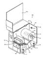
以下、本発明のプリンタの実施の形態について詳細に説明する。図1および図2に本発明のプリンタ50を示す。図1は本発明のプリンタの一実施形態を示す概略側面図、図2はプリンタの斜視図である。
Hereinafter, embodiments of the printer of the present invention will be described in detail. 1 and 2 show a
本発明のプリンタ50は、印字媒体供給部51と印字部61を筐体52内に設けたものである。筐体52は、蝶番を介して矢印方向に揺動して開閉可能な蓋体52a、底面53、三方向の側面54およびフロントパネル59からなる。図2は蓋体52aを開いた状態である。印字媒体供給部51の供給軸55には、印字媒体としてラベル10の連続体を支管に巻いたラベルロール12が回転可能に支持され、ストッパで留められている。ラベル10の走行経路に沿って、ガイドバー56、ラベル10の連続体の有無を検知する用紙センサ57、ラベルのインターバルを検出するピッチセンサ58が配置されている。
The
下流側の印字部61は、プラテンローラ62と、前記プラテンローラ62とともにラベル10の連続体を押圧保持するサーマルヘッド63で構成される。サーマルヘッド63はレバー64の動作により開閉する仕組み、即ち、プラテンローラ62に押し付けたり離間する仕組みである。筐体52の印字部61の隣接位置には発行口65が設けられる。
The
筐体52の底面53には吸着面を下方に向けた吸盤71が取り付けられている。吸盤71は底面53に設けた螺子孔72と螺合したボルト73の先端に連結部材74を介して連結し、ボルト73を回すことによって底面53からの距離、即ち突き出し長さを変更可能にしている。
A
筐体の側面54(背面)には、吸着面を水平方向に向けた吸盤81が取り付けられている。この吸盤81も先に説明した底面53の吸盤71と同様に側面54に設けた螺子孔82と螺合したボルト83の先端に連結し、ボルト83を回すことにより側面54からの突き出し長さを変更可能である。
A
このプリンタ50は、以下のように動作する。プラテンローラ62が回転すると、ラベルロール12から巻き出されたラベル10の連続体は、ガイドバー56、用紙センサ57、ピッチセンサ58を経て印字部61に至り、サーマルヘッド63の発熱走査で感熱発色剤が発色し、ラベル10に文字やバーコード等の画像が印字される。印字が行なわれたラベル10は発行口65から外部に至る。
The
次に、このプリンタの設置方法を説明する。プリンタの設置場所として、食品加工所等のステンレス板が敷かれた作業台20を例にあげる。 Next, a method for installing this printer will be described. As an example of a printer installation location, a work table 20 on which a stainless steel plate is laid is taken as an example.
プリンタ50を作業台20の設置位置に載せ、プリンタ50の上部を作業台20方向、
即ち下向きに押しつける。すると吸盤内部の空気が抜けて作業台20に吸い付き、プリンタ50が作業台20に固定される。プリンタ50が水平になるように調整したい場合は、吸盤に連結したボルトを回し、突き出し長さを増減すれば良い。
The
That is, press downward. Then, the air inside the suction cup escapes and sucks onto the work table 20, and the
この状態でプリンタ50に物がぶつかっても、底面53の吸盤71が作業台20の表面に強く吸着しているため、プリンタ50が作業台20から落下することはなく、破損が未然に防止される。また、地震による大きな揺れを受けた場合でも、プリンタ50は作業台20から落下することがない。
Even if an object collides with the
例えばプリンタ50の側面54のひとつである背面側に平滑な壁面30がある場合(例えば、ステンレス板を打ち付けた壁や、表面が平滑なタイルなど)は、筐体52の背面にあたる側面54から突き出した吸盤81も利用して固定可能である。背面の側面54を壁面30に近づけるとともに壁面30と平行にし、その位置関係を保ったままプリンタ50を作業台20に載せて下方へ押しつける。すると底面53の吸盤71内の空気が抜けて、吸盤71が作業台20に吸着し、固定される。続いてプリンタ50の背面のボルト83を回し、その突き出し長さを増やして吸盤81を壁面30に押し付けていく。吸盤81内の空気が抜けると吸盤81は壁面30に吸着固定される。
For example, when there is a
この状態でプリンタ50に人や物がぶつかったり、地震による大きな揺れを受けた場合でも底面53の吸盤71と側面の吸盤81とが作業台20の表面や壁面30に強く吸着しているため、プリンタ50が作業台20から落下することがなく、落下による破損が未然に防止される。
In this state, even when a person or object collides with the
プリンタ50を移動する際は吸盤71や吸盤81内部に空気を入れて吸着力を低下させ、吸盤71・81を外すだけで良い。吸盤71・81を外してプリンタ50を移動しても、作業台20や壁面30に孔を開けていないため、美観は保たれている。
When moving the
上記で説明した本発明の実施形態では、感熱紙製のラベル10に印字するサーマル紙専用のラベルプリンタを例に説明したが、紙やフィルム製のラベル等に熱転写リボンで印字する熱転写方式のプリンタでも構わない。
In the embodiment of the present invention described above, a label printer dedicated to thermal paper that prints on the
プリンタで印字するラベル10の種類や材質は、感熱紙(サーマル紙)や紙や合成樹脂フィルムなどに限らず、粘着紙として一般的に用いられているものを使用できる。例えば、上質紙、コート紙、アート紙のような紙基材、PET(ポリエチレンテレフタレート)、PE(ポリエチレン)、PP(ポリプロピレン)、PS(ポリスチレン)を素材とした合成樹脂フィルムや、前記の合成樹脂を複数種組み合わせたシート、合成樹脂フィルムと紙とを合わせた複合シートも使用できる。
The type and material of the
なお、本発明が前述した実施の形態に限定されず、本発明の技術思想の範囲内において、各実施の形態は適宜変更され得ることは明らかである。また、上記構成部材の数、位置、形状、配置等は上記実施の形態に限定されず、本発明を実施する上で好適な数、位置、形状等にすることができる。 It should be noted that the present invention is not limited to the above-described embodiments, and it is obvious that each embodiment can be appropriately changed within the scope of the technical idea of the present invention. In addition, the number, position, shape, arrangement, and the like of the above-described constituent members are not limited to the above-described embodiment, and can be set to a suitable number, position, shape, and the like for carrying out the present invention.
10 ラベル
12 ラベルロール
20 作業台
30 壁面
50 プリンタ
51 印字媒体供給部
52 筐体
52a 蓋体
53 底面
54 側面
55 供給軸
56 ガイドバー
57 用紙センサ
58 ピッチセンサ
59 操作パネル
61 印字部
62 プラテンローラ
63 サーマルヘッド
64 レバー
65 発行口
71 吸盤
72 螺子孔
73 ボルト
74 連結部材
81 吸盤
82 螺子孔
83 ボルト
84 連結部材
DESCRIPTION OF
Claims (4)
前記筐体の一または複数箇所に、吸着面を筐体外方へ向けて吸盤が取り付けてあることを特徴とするプリンタ。 A printing medium is conveyed by rotational driving of the platen roller while pressing and holding the printing medium by a casing having at least a bottom surface and a side surface, a printing medium supply unit for supplying the printing medium, and a platen roller and a thermal head. A printer including a printing unit for recording information,
A printer, wherein a suction cup is attached to one or a plurality of locations of the casing with the suction surface facing outward of the casing.
前記筐体の一または複数箇所に、吸着面を筐体外方へ向けて吸盤を取り付け、
前記吸盤をプリンタの設置箇所の載置面およびプリンタに近接した面の一方または両方に吸着固定することを特徴とするプリンタの固定方法。 A printing medium is conveyed by rotational driving of the platen roller while pressing and holding the printing medium by a casing having at least a bottom surface and a side surface, a printing medium supply unit for supplying the printing medium, and a platen roller and a thermal head. A printer including a printing unit for recording information;
A suction cup is attached to one or a plurality of locations of the casing with the suction surface facing the outside of the casing,
A method of fixing a printer, comprising sucking and fixing the suction cup to one or both of a placement surface of a printer installation location and a surface close to the printer.
Priority Applications (1)
| Application Number | Priority Date | Filing Date | Title |
|---|---|---|---|
| JP2011018453A JP2012158043A (en) | 2011-01-31 | 2011-01-31 | Printer |
Applications Claiming Priority (1)
| Application Number | Priority Date | Filing Date | Title |
|---|---|---|---|
| JP2011018453A JP2012158043A (en) | 2011-01-31 | 2011-01-31 | Printer |
Publications (1)
| Publication Number | Publication Date |
|---|---|
| JP2012158043A true JP2012158043A (en) | 2012-08-23 |
Family
ID=46838988
Family Applications (1)
| Application Number | Title | Priority Date | Filing Date |
|---|---|---|---|
| JP2011018453A Pending JP2012158043A (en) | 2011-01-31 | 2011-01-31 | Printer |
Country Status (1)
| Country | Link |
|---|---|
| JP (1) | JP2012158043A (en) |
Cited By (4)
| Publication number | Priority date | Publication date | Assignee | Title |
|---|---|---|---|---|
| CN103587258A (en) * | 2013-11-14 | 2014-02-19 | 安徽天斯努信息技术有限公司 | Cloud printer armor |
| CN106626821A (en) * | 2016-11-17 | 2017-05-10 | 安徽天斯努信息技术股份有限公司 | Printer protection rack with sucking discs |
| CN111016447A (en) * | 2019-12-27 | 2020-04-17 | 夏士桀 | Safe and reliable bar code printer with fixing function |
| JP2021178438A (en) * | 2020-05-12 | 2021-11-18 | コニカミノルタ株式会社 | Image formation apparatus |
-
2011
- 2011-01-31 JP JP2011018453A patent/JP2012158043A/en active Pending
Cited By (6)
| Publication number | Priority date | Publication date | Assignee | Title |
|---|---|---|---|---|
| CN103587258A (en) * | 2013-11-14 | 2014-02-19 | 安徽天斯努信息技术有限公司 | Cloud printer armor |
| CN106626821A (en) * | 2016-11-17 | 2017-05-10 | 安徽天斯努信息技术股份有限公司 | Printer protection rack with sucking discs |
| CN106626821B (en) * | 2016-11-17 | 2019-01-11 | 安徽天斯努信息技术股份有限公司 | A kind of suctorial printer fender bracket of band |
| CN111016447A (en) * | 2019-12-27 | 2020-04-17 | 夏士桀 | Safe and reliable bar code printer with fixing function |
| CN111016447B (en) * | 2019-12-27 | 2021-11-05 | 夏士桀 | A barcode printer with fixed function |
| JP2021178438A (en) * | 2020-05-12 | 2021-11-18 | コニカミノルタ株式会社 | Image formation apparatus |
Similar Documents
| Publication | Publication Date | Title |
|---|---|---|
| KR100795896B1 (en) | Document carrier | |
| US8403286B2 (en) | Three-dimensional printing device | |
| JP2012158043A (en) | Printer | |
| US20130276986A1 (en) | Fold-Under Pressure Sensitive Shipping Labels And Print And Apply Machines For Labeling Packages Using Same | |
| WO2017150184A1 (en) | Printer | |
| JP5671853B2 (en) | Labeling device | |
| WO2003065332A1 (en) | Advertising method using delivery truck | |
| JP6854608B2 (en) | Printer | |
| JP2014008679A (en) | Printer and printing method | |
| JP2006321611A (en) | Winding device, and printer using the same | |
| WO2007144263A1 (en) | Process for printing and coating, and apparatus implementing the process | |
| US20200031112A1 (en) | Metal photographic plate with carrier and method of use. | |
| JP5057098B2 (en) | Printer roll paper set structure | |
| US7390362B2 (en) | Thermal printer | |
| CN206536988U (en) | The flying print movement of a compatible three kinds of printing papers | |
| JP2004045698A5 (en) | ||
| JP2004075392A5 (en) | ||
| US10987947B2 (en) | Metal photographic plate with carrier and method of use | |
| US7789036B2 (en) | Compact glazing machine | |
| JP3164637U (en) | Label printer paper or sticker with wireless tag | |
| JP2591558Y2 (en) | Paper feeder for computer desktop printer | |
| JP2006260396A5 (en) | ||
| CN214324646U (en) | Novel printing head | |
| JP4337477B2 (en) | Image recording medium | |
| CN215944052U (en) | Printer head pressure adjustable bar code printer |
Legal Events
| Date | Code | Title | Description |
|---|---|---|---|
| A711 | Notification of change in applicant |
Free format text: JAPANESE INTERMEDIATE CODE: A712 Effective date: 20130418 |