JP2012159242A - Refrigerating unit - Google Patents
Refrigerating unit Download PDFInfo
- Publication number
- JP2012159242A JP2012159242A JP2011019573A JP2011019573A JP2012159242A JP 2012159242 A JP2012159242 A JP 2012159242A JP 2011019573 A JP2011019573 A JP 2011019573A JP 2011019573 A JP2011019573 A JP 2011019573A JP 2012159242 A JP2012159242 A JP 2012159242A
- Authority
- JP
- Japan
- Prior art keywords
- refrigerant
- accumulator
- refrigeration unit
- pipe
- filling chamber
- Prior art date
- Legal status (The legal status is an assumption and is not a legal conclusion. Google has not performed a legal analysis and makes no representation as to the accuracy of the status listed.)
- Pending
Links
Images



Landscapes
- Air-Conditioning For Vehicles (AREA)
Abstract
【課題】冷媒注入に際し現場での弁操作が不要であり、コストダウンを図ることができる冷凍ユニットを提供する。
【解決手段】少なくとも圧縮機1、アキュムレータ2及びレシーバ8を備えており、設置箇所において冷媒配管と接続されることで冷凍サイクルを構成する冷凍ユニットR。前記アキュムレータ2及びレシーバ8の少なくとも一方の内部に、前記冷凍サイクルに必要な量の冷媒が充填される冷媒充填室15が設けられている。前記冷媒充填室15内と、前記アキュムレータ2及びレシーバ8の少なくとも一方の内部であって当該冷媒充填室15以外の空間とを繋ぐ流路が、前記冷媒充填室15内の冷媒の昇圧により破砕可能な破裂板17で閉止されている。
【選択図】図3There is provided a refrigeration unit that does not require an on-site valve operation when injecting refrigerant and can reduce costs.
A refrigeration unit R includes at least a compressor 1, an accumulator 2, and a receiver 8, and is connected to a refrigerant pipe at an installation location to constitute a refrigeration cycle. Inside at least one of the accumulator 2 and the receiver 8, there is provided a refrigerant filling chamber 15 that is filled with an amount of refrigerant necessary for the refrigeration cycle. A flow path connecting the inside of the refrigerant filling chamber 15 and at least one of the accumulator 2 and the receiver 8 and a space other than the refrigerant filling chamber 15 can be crushed by increasing the pressure of the refrigerant in the refrigerant filling chamber 15. It is closed with a rupturable plate 17.
[Selection] Figure 3
Description
本発明は冷凍ユニットに関する。さらに詳しくは、設置箇所(現場)における冷媒充填が不要である冷凍ユニットに関する。 The present invention relates to a refrigeration unit. More specifically, the present invention relates to a refrigeration unit that does not require refrigerant filling at an installation location (site).
現場における冷媒の充填作業を省略するために、例えばビル用の空気調和装置における室外ユニット(圧縮機や室外側熱交換器などが内蔵されている)の配管内に予め工場において必要量の冷媒を封入することが行われている(従来技術1)。この場合、室外ユニットのガス管及び液管の端部近傍には、当該室外ユニットの保管及び輸送時における冷媒の漏れを防ぐために開閉弁がそれぞれ配設されている。 In order to omit the work of charging the refrigerant at the site, for example, a necessary amount of refrigerant is preliminarily placed in the factory in the piping of an outdoor unit (a compressor, an outdoor heat exchanger, etc. are incorporated) in a building air conditioner. Encapsulation is performed (prior art 1). In this case, an open / close valve is provided in the vicinity of the ends of the gas pipe and the liquid pipe of the outdoor unit to prevent leakage of the refrigerant during storage and transportation of the outdoor unit.
現場では、前記室外ユニットのガス管及び液管の各端部を、室内ユニットに接続された所定の冷媒配管に接続して冷凍サイクルを完成させ、ついで室内ユニット側の冷媒配管内の真空引きを行った後に前記両開閉弁を開状態にすることで、室外ユニットの配管内に充填されていた冷媒を冷凍サイクル内全体に充填させることができる。 At the site, the ends of the gas pipe and liquid pipe of the outdoor unit are connected to a predetermined refrigerant pipe connected to the indoor unit to complete the refrigeration cycle, and then the vacuum in the refrigerant pipe on the indoor unit side is evacuated. After the operation, the both open / close valves are opened so that the refrigerant filled in the piping of the outdoor unit can be filled in the entire refrigeration cycle.
一方、特許文献1では、配管内ではなく、冷凍サイクルを構成する要素であるアキュムレータ内に予め必要量の冷媒を封入することが提案されている(従来技術2)。従来技術2では、図5に示されるように、冷凍サイクルCにおけるアキュムレータ50が二重壁構造にされており、内筒51と外筒52との間の空間は仕切板53により仕切られている。仕切板53により仕切られた一方の空間は予め内部の空気を抜いて真空にした真空容器54とされ、他方の空間は予め内部を冷媒で満たした冷媒容器55とされている。
On the other hand,
前記真空容器54には、当該真空容器54内と配管56内とを連通状態又は非連通状態にする開閉弁58が配設されており、一方、前記冷媒容器55には、当該冷媒容器55内と配管57内とを連通状態又は非連通状態にする開閉弁59が配設されている。
The
アキュムレータ50は、両開閉弁58、59が閉じられた状態で配管56の端部を配管60の端部に接続し、配管57の端部を配管61の端部に接続することで冷凍サイクル中に組み込まれる。そして、開閉弁58を開くことで冷凍サイクル内の真空引きを行い、ついで開閉弁58を閉じた後に開閉弁59を開くことで冷凍サイクル中に冷媒容器55内の冷媒が注入される。
The
しかしながら、従来技術1では、室外ユニットのガス管及び液管の端部近傍にそれぞれ開閉弁を設け、これらの開閉弁の操作により冷凍サイクル中に冷媒を注入しており、冷媒注入に際し現場での弁操作が必要である。また、開閉弁を2つ設ける必要があり、コストアップの要因となっている。
However, in the
また、従来技術2でも、開閉弁の操作により冷凍サイクル中に冷媒を注入しており、冷媒注入に際し現場での弁操作が必要である。また、開閉弁を2つ設ける必要があるとともに、真空容器及び冷媒容器を得るためにアキュムレータを二重壁構造にする必要があるので、コストアップの要因となっている。
Also in the
本発明は、このような事情に鑑みてなされたものであり、冷媒注入に際し現場での弁操作が不要であり、コストダウンを図ることができる冷凍ユニットを提供することを目的としている。 The present invention has been made in view of such circumstances, and an object of the present invention is to provide a refrigeration unit that does not require on-site valve operation when injecting refrigerant and can reduce costs.
(1)本発明の第1の観点に係る冷凍ユニットは、少なくとも圧縮機、アキュムレータ及びレシーバを備えており、設置箇所において冷媒配管と接続されることで冷凍サイクルを構成する冷凍ユニットであって、
前記アキュムレータ及びレシーバの少なくとも一方の内部に、前記冷凍サイクルに必要な量の冷媒が充填される冷媒充填室が設けられており、
前記冷媒充填室内と、前記アキュムレータ及びレシーバの少なくとも一方の内部であって当該冷媒充填室以外の空間とを繋ぐ流路が、前記冷媒充填室内の冷媒の昇圧により破砕可能な破裂板で閉止されていることを特徴としている。
(1) The refrigeration unit according to the first aspect of the present invention includes at least a compressor, an accumulator, and a receiver, and is a refrigeration unit that constitutes a refrigeration cycle by being connected to a refrigerant pipe at an installation location,
Inside the at least one of the accumulator and the receiver, there is provided a refrigerant filling chamber filled with an amount of refrigerant necessary for the refrigeration cycle,
A flow path that connects the refrigerant filling chamber and at least one of the accumulator and the receiver and a space other than the refrigerant filling chamber is closed with a rupture plate that can be crushed by boosting the refrigerant in the refrigerant filling chamber. It is characterized by being.
(2)本発明の第2の観点に係る冷凍ユニットは、前記(1)の冷凍ユニットにおいて、前記破裂板に代えて、加熱により溶融可能な溶栓が配設されていることを特徴としている。 (2) The refrigeration unit according to the second aspect of the present invention is characterized in that, in the refrigeration unit of (1), a melting plug that can be melted by heating is provided instead of the rupturable plate. .
本発明の第1の観点及び第2の観点に係る冷凍ユニットでは、アキュムレータ及びレシーバの少なくとも一方の内部に冷媒充填室が設けられている。そして、前記冷媒充填室内と、前記アキュムレータ及びレシーバの少なくとも一方の内部であって当該冷媒充填室以外の空間とを繋ぐ流路が破裂板(第1の観点に係る冷凍ユニット)又は溶栓(第2の観点に係る冷凍ユニット)で閉止されている。破裂板は、冷媒充填室内の冷媒の昇圧により破砕可能であるので、流路の近傍に電熱コイルなどの加熱手段を配置して当該電熱コイルに通電することで当該流路を介して冷媒を昇温(昇圧)し、破裂板を破砕することができる。また、溶栓は、流路の近傍に電熱コイルなどの加熱手段を配置して当該電熱コイルに通電することで溶栓を加熱して溶融させることができる。 In the refrigeration unit according to the first and second aspects of the present invention, a refrigerant charging chamber is provided in at least one of the accumulator and the receiver. A flow path connecting the refrigerant filling chamber and at least one of the accumulator and the receiver and a space other than the refrigerant filling chamber is a rupturable plate (a refrigeration unit according to the first aspect) or a fusing plug (first The refrigeration unit according to the second aspect). Since the rupturable plate can be crushed by increasing the pressure of the refrigerant in the refrigerant filling chamber, a heating means such as an electric heating coil is arranged near the flow path and the electric heating coil is energized to raise the refrigerant through the flow path. The rupture disc can be crushed by warming (pressurizing). Further, the plug can be heated and melted by disposing heating means such as an electric heating coil in the vicinity of the flow path and energizing the electric heating coil.
電熱コイルへの通電は、例えば冷凍ユニットの試運転ボタンの操作により開始させることができるので、ユーザは、現場で弁操作をすることなく、冷凍サイクル中への冷媒充填を行うことができる。
また、破裂板や溶栓、及びそれを破砕又は溶融させるための加熱手段は、開閉弁に比べて安価であるので、全体として低コスト化を図ることができる。
Since energization of the electric heating coil can be started, for example, by operating a test run button of the refrigeration unit, the user can charge the refrigerant into the refrigeration cycle without operating the valve on site.
In addition, since the rupture disk, the melt plug, and the heating means for crushing or melting the rupture disk are cheaper than the on-off valve, the overall cost can be reduced.
(3)前記(1)の冷凍ユニットにおいて、前記破裂板が配設された流路の近傍に加熱源が配設されていてもよい。この場合、加熱源を作動させることで流路を介して冷媒充填室内の冷媒を加熱することができる。 (3) In the refrigeration unit of (1), a heating source may be disposed in the vicinity of the flow path in which the rupturable plate is disposed. In this case, the refrigerant in the refrigerant filling chamber can be heated through the flow path by operating the heating source.
(4)前記(2)の冷凍ユニットにおいて、前記溶栓が配設された流路の近傍に加熱源が配設されていてもよい。この場合、加熱源を作動させることで溶栓を加熱して溶融させることができる。 (4) In the refrigeration unit of (2), a heating source may be provided in the vicinity of the flow path in which the melting plug is provided. In this case, the melting plug can be heated and melted by operating the heating source.
(5)前記(3)又は(4)の冷凍ユニットにおいて、前記加熱源が、冷凍ユニットの試運転指示により加熱を開始するよう構成されていることが好ましい。この場合、例えば冷凍ユニットの試運転ボタンを押すという簡単な操作により、流路の近傍に配設された加熱源による加熱を開始させることができる。この加熱源による加熱により破裂板を破砕するか、又は溶栓を溶融させることができ、その結果、冷媒充填室内に予め充填されている冷媒を冷凍サイクル中に注入することができる。 (5) In the refrigeration unit of (3) or (4), it is preferable that the heating source is configured to start heating in response to a trial operation instruction of the refrigeration unit. In this case, for example, by a simple operation of pressing a trial operation button of the refrigeration unit, heating by a heat source disposed in the vicinity of the flow path can be started. The rupturable plate can be crushed or the plug can be melted by heating with this heating source, and as a result, the refrigerant pre-filled in the refrigerant filling chamber can be injected into the refrigeration cycle.
(6)前記(1)〜(5)の冷凍ユニットにおいて、前記流路が、前記冷媒充填室から前記アキュムレータ及びレシーバの少なくとも一方の壁部を貫通して外部に延設され、ついで前記壁部を外部側から貫通して前記アキュムレータ及びレシーバの少なくとも一方の内部であって当該冷媒充填室以外の空間に開口する配管からなり、
前記破裂板又は溶栓が、前記壁部の外部の配管内に設けられていてもよい。この場合、配管内に設けられた破裂板又は溶栓を加熱することで、破裂板を破砕するか、又は溶栓を溶融させることができ、その結果、冷媒充填室内に予め充填されている冷媒を冷凍サイクル中に注入することができる。
(6) In the refrigeration unit according to (1) to (5), the flow path extends from the refrigerant charging chamber to the outside through at least one wall portion of the accumulator and the receiver, and then the wall portion. Consisting of a pipe that penetrates from the outside side and opens to a space other than the refrigerant charging chamber inside at least one of the accumulator and receiver,
The rupturable plate or the plug may be provided in a pipe outside the wall portion. In this case, the rupturable plate or the spigot provided in the pipe can be heated to crush the rupturable plate or to melt the splicer. As a result, the refrigerant prefilled in the refrigerant filling chamber Can be injected into the refrigeration cycle.
本発明の冷凍ユニットによれば、冷媒注入に際し現場での弁操作が不要であり、コストダウンを図ることができる。 According to the refrigeration unit of the present invention, on-site valve operation is unnecessary when injecting the refrigerant, and the cost can be reduced.
以下、添付図面を参照しつつ、本発明の冷凍ユニットの実施の形態を詳細に説明する。
図1は、本発明の一実施の形態に係る冷凍ユニットRの冷媒回路図である。冷凍ユニットRはビル用の空気調和装置の室外ユニット(室外機)からなり、主として、圧縮機1、アキュムレータ2、油分離器3、四路切換弁4、室外側熱交換器5、室外ファン6、膨張弁7a、7b、及びレシーバ(受液器)8を備えている。図示しない1又は複数の室内ユニットの冷媒配管に接続されるガス管9及び液管10の各端部には、冷凍ユニットRの保管時や輸送時において、配管内にほこりなどの異物が侵入するのを防止するためのゴム製のキャップ11が被着されている。
Hereinafter, embodiments of the refrigeration unit of the present invention will be described in detail with reference to the accompanying drawings.
FIG. 1 is a refrigerant circuit diagram of a refrigeration unit R according to an embodiment of the present invention. The refrigeration unit R is composed of an outdoor unit (outdoor unit) of a building air conditioner, and mainly includes a
四路切換弁4は、冷房運転サイクルと暖房運転サイクルとを切り替えることができる。冷房運転時には、図1において実線で示される接続状態となり、圧縮機1から、油分離器3、室外側熱交換器5、レシーバ8、室内側熱交換器(図示せず)及びアキュムレータ2を経て当該圧縮機1へと戻る冷房運転サイクルが構成される。一方、暖房運転時には、図1において破線で示される接続状態となり、圧縮機1から、油分離器3、室内側熱交換器(図示せず)、レシーバ8、室外側熱交換器5及びアキュムレータ2を経て当該圧縮機1へと戻る暖房運転サイクルが構成される。
The four-way switching valve 4 can switch between a cooling operation cycle and a heating operation cycle. During the cooling operation, a connection state indicated by a solid line in FIG. 1 is established, and the
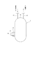
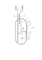
図2は、図1に示されるアキュムレータ2の正面説明図であり、図3は、その内部構造を示す断面説明図であり、図4は、図3のA方向から見た断面説明図である。
アキュムレータ2は、中間部分が円筒状であり、両端がドーム状の金属製容器からなっている。アキュムレータ2の上面部2aに、蒸発器(冷房運転サイクルにおける室内側熱交換器)からの冷媒ガスの入口管12、及び圧縮機1への冷媒ガスの出口管13が接続されている。入口管12の端部12aは、図3〜4に示されるように、アキュムレータ2の内部空間Sの上方部分で開口している。一方、出口管13は、前記内部空間S内において略J字状をなるように曲げられており、その端部13aは、アキュムレータ2の内部空間Sの上下方向(図3〜4において上下方向)の中央やや下方部分で開口している。
2 is a front explanatory view of the
The
アキュムレータ2の内部には、隔壁14によって冷媒充填室15が形成されている。冷媒充填室15は、アキュムレータ2の内部空間Sの上方部分に設けられている。冷媒充填室15内には、本実施の形態に係る冷凍ユニットR及び室内ユニット(図示せず)により構成される冷凍サイクルを機能させるために必要な量の冷媒が充填される。
A
本実施の形態では、冷媒充填室15の内部と、アキュムレータ2の内部空間Sであって当該冷媒充填室15以外の空間とを繋ぐ配管16からなる流路が設けられている。この配管16は、冷媒充填室15の底部隔壁14aから、アキュムレータ2の円筒状の壁部2bを貫通して当該アキュムレータ2の外部に延設され、ついで前記壁部2bを外部側から貫通して前記アキュムレータ2の内部空間Sであって当該冷媒充填室15以外の空間に開口している。
In the present embodiment, a flow path including a
アキュムレータ2の外部における配管16内には、通常の破裂板17(圧力容器などの安全装置として一般に採用されている破裂板)が配設されており、この破裂板17によって配管16が閉止されている。
破裂板17が配設されている配管部分の周囲には、ニクロム線などからなる加熱手段18が設けられている。この加熱手段18は、冷凍ユニットRの全体制御基板(図示せず)の制御部からの指示信号により加熱を開始するように構成されている。
A normal rupture plate 17 (a rupture plate generally used as a safety device such as a pressure vessel) is disposed in the
Around the pipe portion where the
アキュムレータ2の内部空間Sに開口している配管16の端部近傍には、フィルタ19が配設されている。
次に本実施の形態に係る冷凍ユニットRの冷媒充填方法について説明する。
まず、工場段階において、アキュムレータ2の冷媒充填室15内に所定量の冷媒が充填される。この所定量とは、冷凍ユニットR及び室内ユニットからなる冷凍サイクルを機能させるのに必要な量のことであり、圧縮機の出力や配管長などに基づいて予め設定される。工場において冷媒を充填することができるので、充填作業及び検査が容易である。なお、ガス管9及び液管10の各端部にはゴム製のキャップ11が被着される。
A
Next, the refrigerant filling method of the refrigeration unit R according to the present embodiment will be described.
First, in the factory stage, a predetermined amount of refrigerant is filled in the
現場において、前記ゴム製のキャップ11が外され、ついでガス管9及び液管10の各端部と、室内ユニットの冷媒配管の端部とが接続されて冷凍サイクルが構成される。
ついで、冷凍サイクル内が真空引きされて所定の真空圧にされ、その後、加熱手段18が作動され、アキュムレータ2の外部の配管16であって破裂板17が配設された部分が加熱される。加熱手段18によって、配管16を介して冷媒充填室15内に充填されている冷媒が加熱されて圧力が上昇する。そして、所定の圧力以上になると前記破裂板17が破砕し、冷媒充填室15内の冷媒は差圧によりアキュムレータ2の内部空間S内に放出され、冷凍サイクルを構成する機器や配管内に順次移動する。これにより、現場において弁操作をすることなく、冷凍サイクル内に必要量の冷媒を充填させることができる。
At the site, the
Next, the inside of the refrigeration cycle is evacuated to a predetermined vacuum pressure, and then the heating means 18 is operated to heat a portion of the piping 16 outside the
破砕した破裂板17の破片の殆どの部分は、フィルタ19により捕捉されるか、又はアキュムレータ2内に沈殿する。一方、アキュムレータ2の出口管13から圧縮機1側に移動した微細な破片は、当該圧縮機1への配管入口に配設されたフィルタ(図示せず)により捕捉される。したがって、破裂板17の破片が冷媒ガスとともに圧縮機1内に混入することはない。
Most of the broken pieces of the
加熱手段18は、冷凍サイクルの試運転開始指示のより加熱を開始するようにすることができる。この場合、冷凍ユニットRの全体制御基板などに設けられた試運転ボタンを押すという簡単な操作により、加熱手段18による配管16の加熱を開始させることができる。
The heating means 18 can start heating in response to an instruction to start a trial operation of the refrigeration cycle. In this case, the heating of the
〔その他の変形例〕
なお、本発明は前述した実施の形態に限定されるものではなく、特許請求の範囲内において種々の変更が可能である。例えば、前述した実施の形態では、冷媒充填室からの配管内に破裂板が配設されているが、この破裂板に代えて加熱により溶融する通常の溶栓(圧力容器などの安全装置として一般に採用されている溶栓)を用いることができる。かかる溶栓の材料は、本発明において特に限定されるものではないが、例えばインジウム63.5質量%、ビスマス35質量%、錫0.5質量%、及びアンチモン1.0%からなる合金を用いることができる。この場合、溶融した溶栓の殆どの部分は、フィルタ19により捕捉されるか、又はアキュムレータ2内に沈殿する。一方、アキュムレータ2の出口管13から圧縮機1側に移動した微細な溶融片は、当該圧縮機1への配管入口に配設されたフィルタ(図示せず)により捕捉される。したがって、溶栓の溶融片が冷媒ガスとともに圧縮機1内に混入することはない。
[Other variations]
The present invention is not limited to the embodiments described above, and various modifications can be made within the scope of the claims. For example, in the above-described embodiment, a rupturable plate is disposed in the pipe from the refrigerant filling chamber, but instead of this rupturable plate, a normal melting plug (generally used as a safety device such as a pressure vessel) that melts by heating. Adopted fusing plugs) can be used. The material of the fusing plug is not particularly limited in the present invention. For example, an alloy composed of 63.5% by mass of indium, 35% by mass of bismuth, 0.5% by mass of tin, and 1.0% of antimony is used. be able to. In this case, most of the molten plug is captured by the
また、前述した実施の形態では、冷凍ユニットRを構成するアキュムレータ2内に冷媒を充填する冷媒充填室15を設けているが、同じく冷凍ユニットRを構成するレシーバ8内に冷媒充填室を設けることもできる。この場合も、冷媒充填室内と、レシーバ8の内部空間であって当該冷媒充填室以外の空間とを繋ぐ流路である配管内に破裂板又は溶栓が配設される。そして、この破裂板又は溶栓が配設された配管近傍に配設された加熱手段によって当該破裂板を破砕するか、又は溶栓を溶融させることで、冷媒充填室内の冷媒を冷凍サイクル内に充填させることができる。
In the above-described embodiment, the
また、前述した実施の形態では、破裂板17が配設された配管部分に加熱手段18を配設しているが、冷媒充填室15を画定するアキュムレータ2の壁部2cに近接して加熱手段28を配設することもできる(図4の2点鎖線参照)。この場合も、冷媒充填室内の冷媒を加熱することで、配管16内の破裂板17を破砕することができる。
In the embodiment described above, the heating means 18 is disposed in the pipe portion where the
また、前述した実施の形態では、冷媒充填室15からの配管16を一旦アキュムレータ2の外部に延設し、アキュムレータ2の外部の配管16内に破裂板17を配設しているが、図4において2点鎖線で示されるように、冷媒充填室15の底部隔壁14aを貫通する配管26を当該アキュムレータ2の内部空間Sであって前記冷媒充填室15以外の空間に開口させることもできる。この場合、冷媒充填室15を確定するアキュムレータ2の隔壁2cに近接して加熱手段28を配設し、当該冷媒充填室15内の冷媒を加熱することで、配管26内の破裂板27を破砕することができる。
In the above-described embodiment, the
1 圧縮機
2 アキュムレータ
3 油分離器
4 四路切換弁
5 室外側熱交換器
6 室外ファン
7a 膨張弁
7b 膨張弁
8 レシーバ
9 ガス管
10 液管
11 キャップ
14 隔壁
15 冷媒充填室
16 配管
17 破裂板
18 加熱手段
19 フィルタ
R 冷凍ユニット
S 内部空間
DESCRIPTION OF
Claims (6)
前記アキュムレータ(2)及びレシーバ(8)の少なくとも一方の内部に、前記冷凍サイクルに必要な量の冷媒が充填される冷媒充填室(15)が設けられており、
前記冷媒充填室(15)内と、前記アキュムレータ(2)及びレシーバ(8)の少なくとも一方の内部であって当該冷媒充填室(15)以外の空間とを繋ぐ流路が、前記冷媒充填室(15)内の冷媒の昇圧により破砕可能な破裂板(17)で閉止されていることを特徴とする冷凍ユニット(R)。 A refrigeration unit (R) comprising at least a compressor (1), an accumulator (2) and a receiver (8), and constituting a refrigeration cycle by being connected to a refrigerant pipe at an installation location,
In at least one of the accumulator (2) and the receiver (8), a refrigerant filling chamber (15) filled with an amount of refrigerant necessary for the refrigeration cycle is provided,
A flow path connecting the inside of the refrigerant filling chamber (15) and the space inside the at least one of the accumulator (2) and the receiver (8) and other than the refrigerant filling chamber (15) is the refrigerant filling chamber ( 15) A refrigeration unit (R), which is closed by a rupturable plate (17) that can be crushed by increasing the pressure of the refrigerant inside.
前記破裂板(17)又は溶栓が、前記壁部の外部の配管(16)内に設けられている請求項1〜5のいずれかに記載の冷凍ユニット(R)。 The flow path extends from the refrigerant filling chamber (15) to the outside through at least one wall of the accumulator (2) and the receiver (8), and then penetrates the wall from the outside. The pipe (16) is opened in a space other than the refrigerant charging chamber (15) inside at least one of the accumulator (2) and the receiver (8),
The refrigeration unit (R) according to any one of claims 1 to 5, wherein the rupturable plate (17) or the melting plug is provided in a pipe (16) outside the wall portion.
Priority Applications (1)
| Application Number | Priority Date | Filing Date | Title |
|---|---|---|---|
| JP2011019573A JP2012159242A (en) | 2011-02-01 | 2011-02-01 | Refrigerating unit |
Applications Claiming Priority (1)
| Application Number | Priority Date | Filing Date | Title |
|---|---|---|---|
| JP2011019573A JP2012159242A (en) | 2011-02-01 | 2011-02-01 | Refrigerating unit |
Publications (1)
| Publication Number | Publication Date |
|---|---|
| JP2012159242A true JP2012159242A (en) | 2012-08-23 |
Family
ID=46839931
Family Applications (1)
| Application Number | Title | Priority Date | Filing Date |
|---|---|---|---|
| JP2011019573A Pending JP2012159242A (en) | 2011-02-01 | 2011-02-01 | Refrigerating unit |
Country Status (1)
| Country | Link |
|---|---|
| JP (1) | JP2012159242A (en) |
Cited By (2)
| Publication number | Priority date | Publication date | Assignee | Title |
|---|---|---|---|---|
| JP2018025326A (en) * | 2016-08-09 | 2018-02-15 | パナソニックIpマネジメント株式会社 | Refrigeration cycle equipment |
| EP3584521A4 (en) * | 2017-02-14 | 2020-12-30 | Daikin Industries, Ltd. | COOLING DEVICE |
-
2011
- 2011-02-01 JP JP2011019573A patent/JP2012159242A/en active Pending
Cited By (3)
| Publication number | Priority date | Publication date | Assignee | Title |
|---|---|---|---|---|
| JP2018025326A (en) * | 2016-08-09 | 2018-02-15 | パナソニックIpマネジメント株式会社 | Refrigeration cycle equipment |
| EP3584521A4 (en) * | 2017-02-14 | 2020-12-30 | Daikin Industries, Ltd. | COOLING DEVICE |
| US11280523B2 (en) | 2017-02-14 | 2022-03-22 | Daikin Industries, Ltd. | Refrigeration apparatus with leak detection on the usage side and a refrigerant release mechanism |
Similar Documents
| Publication | Publication Date | Title |
|---|---|---|
| JP6380696B2 (en) | Refrigeration equipment | |
| US11274866B2 (en) | Refrigeration apparatus with a refrigerant leakage detection and release mechanism | |
| EP1471312B1 (en) | Refrigerant leakage warning device using flammable refrigerant | |
| EP0756142B1 (en) | Refrigerator | |
| EP2525205A1 (en) | Pressure decay leak check method and apparatus | |
| EP2357432B1 (en) | Refrigerating air-conditioning apparatus | |
| JP5677233B2 (en) | Outdoor unit and refrigeration cycle apparatus including the outdoor unit | |
| JP6634517B2 (en) | Refrigeration cycle device | |
| JP5211894B2 (en) | Air conditioner | |
| CN104567158B (en) | System and method for controlling leakage amount of refrigerant of refrigerator system | |
| TW200813380A (en) | Refrigerant charging method in refrigeration system using carbon dioxide as refrigerant | |
| JP2017067396A (en) | Refrigerant leak location identification method | |
| EP2639516B1 (en) | Heat pump hydronic heater | |
| JP2012159242A (en) | Refrigerating unit | |
| JP2010002111A (en) | Vapor compression type heat pump device | |
| JP2000179958A (en) | Air conditioner | |
| AU704738B2 (en) | Arrangement at a tube evaporator | |
| CN100439826C (en) | Refrigerator with a door | |
| CN202546936U (en) | Integrated explosion-proof air conditioner | |
| CN111174103B (en) | Hydrogen leak prevention device | |
| JP2004286315A (en) | Refrigeration circuit safety device | |
| JP6398373B2 (en) | Air conditioner floor-mounted indoor unit | |
| JP2008082654A (en) | Refrigeration apparatus failure diagnosis method and refrigeration apparatus | |
| CN102762936A (en) | Method for recovering refrigerant from refrigeration equipment | |
| JP2013120006A (en) | Air conditioner |