JP2012159507A - シャフトの変形を測定するための装置及び方法 - Google Patents
シャフトの変形を測定するための装置及び方法 Download PDFInfo
- Publication number
- JP2012159507A JP2012159507A JP2012017440A JP2012017440A JP2012159507A JP 2012159507 A JP2012159507 A JP 2012159507A JP 2012017440 A JP2012017440 A JP 2012017440A JP 2012017440 A JP2012017440 A JP 2012017440A JP 2012159507 A JP2012159507 A JP 2012159507A
- Authority
- JP
- Japan
- Prior art keywords
- pattern
- shaft
- sensor
- deformation
- reference position
- Prior art date
- Legal status (The legal status is an assumption and is not a legal conclusion. Google has not performed a legal analysis and makes no representation as to the accuracy of the status listed.)
- Granted
Links
Images


Classifications
-
- G—PHYSICS
- G01—MEASURING; TESTING
- G01L—MEASURING FORCE, STRESS, TORQUE, WORK, MECHANICAL POWER, MECHANICAL EFFICIENCY, OR FLUID PRESSURE
- G01L3/00—Measuring torque, work, mechanical power, or mechanical efficiency, in general
- G01L3/02—Rotary-transmission dynamometers
- G01L3/04—Rotary-transmission dynamometers wherein the torque-transmitting element comprises a torsionally-flexible shaft
- G01L3/10—Rotary-transmission dynamometers wherein the torque-transmitting element comprises a torsionally-flexible shaft involving electric or magnetic means for indicating
- G01L3/12—Rotary-transmission dynamometers wherein the torque-transmitting element comprises a torsionally-flexible shaft involving electric or magnetic means for indicating involving photoelectric means
Landscapes
- Physics & Mathematics (AREA)
- General Physics & Mathematics (AREA)
- Length Measuring Devices By Optical Means (AREA)
Abstract
【解決手段】 デバイスによってシャフト2の変形を測定するための方法が、変形が加えられる前に、シャフト2に付加されたパターン3を照明するステップと、パターン3によって反射された放射線を検出することによって第1基準位置を検出するステップとから成り、変形が加えられた後に、パターン3を照明するステップと、パターン3によって反射された放射線を検出することによって第2基準位置を検出するステップとから成る。これにより、第1基準位置と第2基準位置との間の距離に基づいて、シャフトの円周方向の変形及び/又はトルクが求められる。
【選択図】 図2
Description
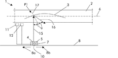
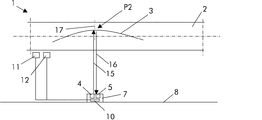
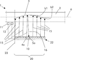
2 シャフト
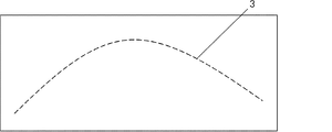
3 パターン
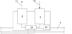
4、4a 放射線源
5、5a センサ
6 シャフト2の軸
7 キャリア
8 方向
8a、8b 方向8の向き
9 レール
10 制御ユニット
11 シャフト2の軸方向位置を感知するセンサ
12 シャフト2の角度を感知するセンサ
15 放射線源4によって発生される光ビーム
16 パターン3によって反射された光ビーム
17 パターン3に垂直な軸
20 パターンに面する区域
21 ディスプレイ
22 アレイ
23 軸6に垂直な軸
a 角度
P1、P2、P3 パターン3上での位置
Claims (15)
- シャフト(2)の変形を測定するためのデバイスを備える、シャフト(2)の装置(1)であって、前記デバイスは、
前記シャフト(2)に付加された曲線パターン(3)、
前記パターン(3)を照明するための放射線源(4)、及び
前記パターン(3)によって反射された前記放射線を検出するためのセンサ(5)を備える当該装置において、
当該装置は、前記パターン(3)に面する区域(20)にわたって前記シャフト軸(6)に対して所定の方向(8)に移動可能なキャリア(7)をさらに備え、このキャリア(7)は、少なくとも前記センサ(5)を担持することを特徴とする装置(1)。 - シャフト(2)の変形を測定するためのデバイスを備える、シャフト(2)の装置(1)であって、前記デバイスは、
前記シャフト(2)に付加された曲線パターン(3)、
前記パターン(3)を照明するための放射線源(4)、及び
前記パターン(3)によって反射された前記放射線を検出するためのセンサ(5)を備え、
前記装置(1)は、前記パターン(3)に面する区域(20)にわたって延在しているアレイ(22)を画定する複数の放射線源(4)と複数のセンサ(5)とを有し、
前記曲線パターン(3)が、前記シャフト軸(6)に対して平行な軸と共に角度(b1、b2)を決定する当該装置(1)において、
前記角度(b1、b2)は、前記曲線パターン(3)にわたって変化することを特徴とする装置(1)。 - 前記キャリア(7)は、前記放射線源(4)も担持することを特徴とする請求項1に記載の装置(1)。
- 前記所定の方向(8)は、前記シャフト軸(6)対してほぼ平行な方向であることを特徴とする請求項1に記載の装置(1)。
- 前記曲線パターン(3)は、前記シャフト軸(6)に対して平行な軸と共に前記曲線パターン(3)にわたって変化する角度を決定することを特徴とする請求項1に記載の装置(1)。
- 前記装置(1)は、前記シャフト(2)の軸方向の位置を感知するセンサ(11)をさらに備えることを特徴とする請求項1又は2に記載の装置(1)。
- 前記装置(1)は、前記パターン(3)が前記放射線源(4)に面する時だけ前記放射線源(4)を作動させるために配置された制御ユニット(10)をさらに備えることを特徴とする請求項1又は2に記載の装置(1)。
- 前記装置(1)は、前記シャフト(2)に関連付けられ且つ前記制御ユニット(10)に接続された角度センサ(12)をさらに備えることを特徴とする請求項7に記載の装置(1)。
- 前記放射線源(4)は、光源であることを特徴とする請求項1又は2に記載の装置(1)。
- 前記光源は、レーザであることを特徴とする請求項9に記載の装置(1)。
- 前記パターン(3)は、角度の付いた複数の離散した線から成ることを特徴とする請求項1又は2に記載の装置(1)。
- デバイスによってシャフト(2)の変形を測定するための方法であって、
前記デバイスは、
前記シャフト(2)に付加された曲線パターン(3)、
前記パターン(3)を照明するための放射線源(4)、
前記パターン(3)によって反射された前記放射線を検出するためのセンサ(5)、及び
前記パターン(3)に面する区域(20)にわたって前記シャフト軸(6)に対して所定の方向(8)に移動可能なキャリア(7)を備え、
前記キャリア(7)が、少なくとも前記センサ(5)を担持するか、又は、前記センサ(5)が、前記パターン(3)に面する区域(20)にわたって延在しているアレイ(22)を画定する複数のセンサ(5)を有する当該方法において、
当該方法は、変形が加えられる前に、
前記パターン(3)を照明するステップと、
前記パターン(3)によって反射された前記放射線を検出することによって第1基準位置を検出するステップとを有し、
前記変形が加えられた後に、
前記パターン(3)を照明するステップと、
前記パターン(3)によって反射された前記放射線を検出することによって第2基準位置を検出するステップと有し、
前記第1基準位置と前記第2基準位置との間の距離に基づいて、前記シャフトの円周方向の変形及び/又はトルクを求めるステップを有する方法。 - 前記キャリア(7)は、前記放射線源(4)も担持することを特徴とする請求項12に記載の方法。
- 前記第1基準位置と前記第2基準位置との間の距離は、前記シャフト軸に対して平行な方向に沿って確定されることを特徴とする請求項12に記載の方法。
- 前記アレイ(22)は、複数の放射線源(4)も備えることを特徴とする請求項12に記載の方法。
Applications Claiming Priority (2)
| Application Number | Priority Date | Filing Date | Title |
|---|---|---|---|
| EP11152834 | 2011-02-01 | ||
| EP11152834.5 | 2011-02-01 |
Publications (2)
| Publication Number | Publication Date |
|---|---|
| JP2012159507A true JP2012159507A (ja) | 2012-08-23 |
| JP5683509B2 JP5683509B2 (ja) | 2015-03-11 |
Family
ID=44835015
Family Applications (1)
| Application Number | Title | Priority Date | Filing Date |
|---|---|---|---|
| JP2012017440A Active JP5683509B2 (ja) | 2011-02-01 | 2012-01-31 | シャフトの変形を測定するための装置及び方法 |
Country Status (4)
| Country | Link |
|---|---|
| US (1) | US8610890B2 (ja) |
| JP (1) | JP5683509B2 (ja) |
| CN (1) | CN102628718B (ja) |
| DE (1) | DE102012001446B4 (ja) |
Families Citing this family (8)
| Publication number | Priority date | Publication date | Assignee | Title |
|---|---|---|---|---|
| US9243603B2 (en) * | 2014-01-10 | 2016-01-26 | Ford Global Technologies, Llc | Laser ignition system based diagnostics |
| KR102372335B1 (ko) * | 2015-07-27 | 2022-03-08 | 삼성디스플레이 주식회사 | 가요성 표시 장치 및 그 구동 방법 |
| DE102015225696A1 (de) | 2015-12-17 | 2017-06-22 | Robert Bosch Gmbh | Verfahren zur Drehmomentmessung einer Antriebseinheit |
| DE102016219962B4 (de) * | 2016-10-13 | 2018-05-03 | Conti Temic Microelectronic Gmbh | Drehmomentmessvorrichtung |
| CN108759780B (zh) * | 2018-09-03 | 2024-02-20 | 刘绍波 | 一种高铁桥墩沉降的光纤光栅监测装置 |
| CN111198057A (zh) * | 2018-11-19 | 2020-05-26 | 北京致感致联科技有限公司 | 风机叶片根部扭矩在线监测系统 |
| CN109738283A (zh) * | 2018-12-10 | 2019-05-10 | 内蒙古第一机械集团股份有限公司 | 一种齿轮受载变形量的测量系统及测量方法 |
| CN116772737A (zh) * | 2023-05-25 | 2023-09-19 | 中国航空工业集团公司金城南京机电液压工程研究中心 | 一种旋转传动轴的非接触实时测量方法与系统 |
Citations (5)
| Publication number | Priority date | Publication date | Assignee | Title |
|---|---|---|---|---|
| JPS56111407A (en) * | 1980-02-08 | 1981-09-03 | Toshiba Corp | Shaft torsion detecting method |
| US4507834A (en) * | 1983-05-27 | 1985-04-02 | Sperry Corporation | Drilling monitor |
| JPH02232402A (ja) * | 1989-01-17 | 1990-09-14 | Linsinger Mas Bau Gmbh | レールのひずみと摩滅を無接触に測定する方法及び装置 |
| JP2002287327A (ja) * | 2001-03-28 | 2002-10-03 | Lasertec Corp | 位相シフトマスクの欠陥検査装置 |
| JP2005221294A (ja) * | 2004-02-04 | 2005-08-18 | Mitsubishi Juko Koji Kk | 形状計測装置および形状計測方法 |
Family Cites Families (15)
| Publication number | Priority date | Publication date | Assignee | Title |
|---|---|---|---|---|
| US4166383A (en) * | 1978-03-20 | 1979-09-04 | The Laitram Corporation | Optical shaft torque meter |
| CA1121174A (en) * | 1979-03-27 | 1982-04-06 | James G. Pierson | Torque transducer |
| US4995257A (en) * | 1989-03-23 | 1991-02-26 | Electric Power Research Institute, Inc. | Monitor for shaft vibration in an operating turbine |
| JPH04344436A (ja) * | 1991-05-22 | 1992-12-01 | Toshiba Corp | 光学式トルク検出装置 |
| US5490430A (en) * | 1992-05-14 | 1996-02-13 | Anderson; Philip M. | Optical torque sensor utilizing change in reflectance grating line spacing |
| JPH074928A (ja) * | 1993-06-15 | 1995-01-10 | Shimadzu Corp | 歪測定装置 |
| JP3636742B2 (ja) * | 1993-12-22 | 2005-04-06 | オムロン株式会社 | 光スキャナ及び光走査装置並びに当該光走査装置を用いた符号情報読み取り装置及びposシステム |
| JP2692599B2 (ja) * | 1994-07-27 | 1997-12-17 | 株式会社島津製作所 | レーザー非接触伸び計 |
| DE19731545C1 (de) * | 1997-07-23 | 1999-05-27 | Basler Gmbh | Vorrichtung und Verfahren zum optischen Erfassen der Verformung einer Fläche |
| JPH11344395A (ja) * | 1998-06-02 | 1999-12-14 | Systemseiko Co Ltd | 回転軸の変形検出方法および装置 |
| US6587211B1 (en) * | 1999-07-28 | 2003-07-01 | Creo Srl | Interferometric torque and power sensor |
| US7322250B1 (en) | 2002-04-09 | 2008-01-29 | Rockwell Automation Technologies, Inc. | System and method for sensing torque on a rotating shaft |
| US7036364B2 (en) * | 2003-09-25 | 2006-05-02 | The Regents Of The University Of Michigan | Optical system and method for measuring continuously distributed strain |
| US8042412B2 (en) | 2008-06-25 | 2011-10-25 | General Electric Company | Turbomachinery system fiberoptic multi-parameter sensing system and method |
| FR2951136B1 (fr) * | 2009-10-14 | 2011-10-21 | Eurocopter France | Mecanisme d'attenuation des pulsations en couple entre un moteur et un rotor de giravion entraine en rotation par ce moteur |
-
2012
- 2012-01-20 CN CN201210022732.1A patent/CN102628718B/zh active Active
- 2012-01-26 DE DE102012001446.5A patent/DE102012001446B4/de active Active
- 2012-01-27 US US13/359,501 patent/US8610890B2/en active Active
- 2012-01-31 JP JP2012017440A patent/JP5683509B2/ja active Active
Patent Citations (5)
| Publication number | Priority date | Publication date | Assignee | Title |
|---|---|---|---|---|
| JPS56111407A (en) * | 1980-02-08 | 1981-09-03 | Toshiba Corp | Shaft torsion detecting method |
| US4507834A (en) * | 1983-05-27 | 1985-04-02 | Sperry Corporation | Drilling monitor |
| JPH02232402A (ja) * | 1989-01-17 | 1990-09-14 | Linsinger Mas Bau Gmbh | レールのひずみと摩滅を無接触に測定する方法及び装置 |
| JP2002287327A (ja) * | 2001-03-28 | 2002-10-03 | Lasertec Corp | 位相シフトマスクの欠陥検査装置 |
| JP2005221294A (ja) * | 2004-02-04 | 2005-08-18 | Mitsubishi Juko Koji Kk | 形状計測装置および形状計測方法 |
Also Published As
| Publication number | Publication date |
|---|---|
| DE102012001446A1 (de) | 2012-08-02 |
| JP5683509B2 (ja) | 2015-03-11 |
| CN102628718B (zh) | 2016-03-16 |
| US8610890B2 (en) | 2013-12-17 |
| DE102012001446B4 (de) | 2020-09-24 |
| US20120194825A1 (en) | 2012-08-02 |
| CN102628718A (zh) | 2012-08-08 |
Similar Documents
| Publication | Publication Date | Title |
|---|---|---|
| JP5683509B2 (ja) | シャフトの変形を測定するための装置及び方法 | |
| US8687206B2 (en) | Optical detection of airfoil axial position with NSMS | |
| JP5310098B2 (ja) | レーザ距離測定装置 | |
| US20120002038A1 (en) | Measuring device for measuring deformations of elastically deformable objects | |
| CN102313634A (zh) | 用于光学测量风力发电设备风轮叶片的挠度的装置 | |
| JP6343325B2 (ja) | レーザスキャナの調整方法 | |
| EP1039262A3 (en) | Sheet thickness and swell measurement method and apparatus therefor | |
| DE602007012317D1 (de) | Compensation von messfehlern aufgrund dynamischer | |
| WO2014000744A3 (en) | Wind turbine blade vibration detection and radar calibration | |
| US9733073B2 (en) | Apparatus for determining the angle between two planar workpiece surfaces | |
| CN101469971B (zh) | 检测真空断路器触头磨损量的方法及其装置 | |
| JP2008057533A5 (ja) | ||
| CA2355496C (en) | Rotary shaft axial elongation measuring method and device | |
| EP3390816B1 (en) | Turbine arrangement | |
| EP2546613B1 (en) | Method for working out the eccentricity and the angular position of a rotating element and Device for carrying out such a method | |
| JP2015087302A (ja) | 配管形状測定装置および配管形状測定方法 | |
| CN110632567B (zh) | 用于初始校准车辆的驾驶员辅助系统的传感器的方法 | |
| JP5455428B2 (ja) | 測定装置 | |
| JP4735079B2 (ja) | タイヤ動的接地形状測定方法 | |
| JP2009271076A6 (ja) | 位置および/または速度を検出する測定装置 | |
| JP5340006B2 (ja) | 帯状部材の形状検出装置 | |
| WO2019027439A1 (en) | TURBINE AND COMPRESSOR VANE DEFORMATION AND AXIAL SHIFT MONITORING BY DEPLOYING AND FOLLOWING PATTERN IN DAWN POCKETS | |
| KR20100072675A (ko) | 레이저와 반사기를 이용한 진동측정장치 | |
| JP2019095299A (ja) | 厚み測定装置 | |
| EP2247916A1 (en) | Measurement arrangement with a measurement head in order to carry out inspection measurement |
Legal Events
| Date | Code | Title | Description |
|---|---|---|---|
| RD03 | Notification of appointment of power of attorney |
Free format text: JAPANESE INTERMEDIATE CODE: A7423 Effective date: 20130628 |
|
| RD04 | Notification of resignation of power of attorney |
Free format text: JAPANESE INTERMEDIATE CODE: A7424 Effective date: 20130703 |
|
| A621 | Written request for application examination |
Free format text: JAPANESE INTERMEDIATE CODE: A621 Effective date: 20130902 |
|
| A977 | Report on retrieval |
Free format text: JAPANESE INTERMEDIATE CODE: A971007 Effective date: 20140219 |
|
| A131 | Notification of reasons for refusal |
Free format text: JAPANESE INTERMEDIATE CODE: A131 Effective date: 20140224 |
|
| A601 | Written request for extension of time |
Free format text: JAPANESE INTERMEDIATE CODE: A601 Effective date: 20140526 |
|
| A602 | Written permission of extension of time |
Free format text: JAPANESE INTERMEDIATE CODE: A602 Effective date: 20140529 |
|
| A601 | Written request for extension of time |
Free format text: JAPANESE INTERMEDIATE CODE: A601 Effective date: 20140624 |
|
| A602 | Written permission of extension of time |
Free format text: JAPANESE INTERMEDIATE CODE: A602 Effective date: 20140627 |
|
| A521 | Request for written amendment filed |
Free format text: JAPANESE INTERMEDIATE CODE: A523 Effective date: 20140630 |
|
| TRDD | Decision of grant or rejection written | ||
| A01 | Written decision to grant a patent or to grant a registration (utility model) |
Free format text: JAPANESE INTERMEDIATE CODE: A01 Effective date: 20150105 |
|
| A61 | First payment of annual fees (during grant procedure) |
Free format text: JAPANESE INTERMEDIATE CODE: A61 Effective date: 20150113 |
|
| R150 | Certificate of patent or registration of utility model |
Ref document number: 5683509 Country of ref document: JP Free format text: JAPANESE INTERMEDIATE CODE: R150 |
|
| S533 | Written request for registration of change of name |
Free format text: JAPANESE INTERMEDIATE CODE: R313533 |
|
| R350 | Written notification of registration of transfer |
Free format text: JAPANESE INTERMEDIATE CODE: R350 |
|
| R250 | Receipt of annual fees |
Free format text: JAPANESE INTERMEDIATE CODE: R250 |
|
| R250 | Receipt of annual fees |
Free format text: JAPANESE INTERMEDIATE CODE: R250 |
|
| R250 | Receipt of annual fees |
Free format text: JAPANESE INTERMEDIATE CODE: R250 |
|
| R250 | Receipt of annual fees |
Free format text: JAPANESE INTERMEDIATE CODE: R250 |
|
| R250 | Receipt of annual fees |
Free format text: JAPANESE INTERMEDIATE CODE: R250 |
|
| R250 | Receipt of annual fees |
Free format text: JAPANESE INTERMEDIATE CODE: R250 |
|
| RD02 | Notification of acceptance of power of attorney |
Free format text: JAPANESE INTERMEDIATE CODE: R3D02 |
|
| R250 | Receipt of annual fees |
Free format text: JAPANESE INTERMEDIATE CODE: R250 |
|
| S111 | Request for change of ownership or part of ownership |
Free format text: JAPANESE INTERMEDIATE CODE: R313113 |
|
| S531 | Written request for registration of change of domicile |
Free format text: JAPANESE INTERMEDIATE CODE: R313531 |
|
| R250 | Receipt of annual fees |
Free format text: JAPANESE INTERMEDIATE CODE: R250 |
|
| R360 | Written notification for declining of transfer of rights |
Free format text: JAPANESE INTERMEDIATE CODE: R360 |
|
| R360 | Written notification for declining of transfer of rights |
Free format text: JAPANESE INTERMEDIATE CODE: R360 |
|
| R371 | Transfer withdrawn |
Free format text: JAPANESE INTERMEDIATE CODE: R371 |
|
| S111 | Request for change of ownership or part of ownership |
Free format text: JAPANESE INTERMEDIATE CODE: R313113 |
|
| S531 | Written request for registration of change of domicile |
Free format text: JAPANESE INTERMEDIATE CODE: R313531 |
|
| R350 | Written notification of registration of transfer |
Free format text: JAPANESE INTERMEDIATE CODE: R350 |
|
| S111 | Request for change of ownership or part of ownership |
Free format text: JAPANESE INTERMEDIATE CODE: R313111 |
|
| R350 | Written notification of registration of transfer |
Free format text: JAPANESE INTERMEDIATE CODE: R350 |