JP2012160938A - Path switching control system and path switching control method - Google Patents
Path switching control system and path switching control method Download PDFInfo
- Publication number
- JP2012160938A JP2012160938A JP2011019728A JP2011019728A JP2012160938A JP 2012160938 A JP2012160938 A JP 2012160938A JP 2011019728 A JP2011019728 A JP 2011019728A JP 2011019728 A JP2011019728 A JP 2011019728A JP 2012160938 A JP2012160938 A JP 2012160938A
- Authority
- JP
- Japan
- Prior art keywords
- path
- optical
- switching control
- control system
- transmission device
- Prior art date
- Legal status (The legal status is an assumption and is not a legal conclusion. Google has not performed a legal analysis and makes no representation as to the accuracy of the status listed.)
- Pending
Links
- 238000000034 method Methods 0.000 title claims description 19
- 230000003287 optical effect Effects 0.000 claims abstract description 197
- 230000005540 biological transmission Effects 0.000 claims abstract description 127
- 230000001172 regenerating effect Effects 0.000 claims abstract description 49
- 238000012546 transfer Methods 0.000 description 8
- 238000011084 recovery Methods 0.000 description 6
- 238000010586 diagram Methods 0.000 description 4
- 238000011144 upstream manufacturing Methods 0.000 description 4
- 230000000694 effects Effects 0.000 description 3
- 230000002159 abnormal effect Effects 0.000 description 1
- 230000002411 adverse Effects 0.000 description 1
- 230000002457 bidirectional effect Effects 0.000 description 1
- 238000004891 communication Methods 0.000 description 1
- 238000011161 development Methods 0.000 description 1
- 230000018109 developmental process Effects 0.000 description 1
- 238000005516 engineering process Methods 0.000 description 1
- 239000000835 fiber Substances 0.000 description 1
- 238000012544 monitoring process Methods 0.000 description 1
- 239000013307 optical fiber Substances 0.000 description 1
- 230000002250 progressing effect Effects 0.000 description 1
- 230000008929 regeneration Effects 0.000 description 1
- 238000011069 regeneration method Methods 0.000 description 1
- 230000015607 signal release Effects 0.000 description 1
- 230000008054 signal transmission Effects 0.000 description 1
- 238000005549 size reduction Methods 0.000 description 1
Images

Landscapes
- Data Exchanges In Wide-Area Networks (AREA)
Abstract
Description
本発明は、光信号の伝送を行う光伝送システムのパス切替制御システムとパス切替制御方法に関する。 The present invention relates to a path switching control system and a path switching control method for an optical transmission system that transmits optical signals.
近年、異なる波長の光を多重化して、1本の光ファイバで同時に複数の信号伝送を行う開発が、光通信の中心技術として急速に進んでいる。 2. Description of the Related Art In recent years, the development of multiplexing light of different wavelengths and simultaneously transmitting a plurality of signals using a single optical fiber is rapidly progressing as a central technology for optical communication.
障害によってシステムが本来の機能を失うと、人命や財産が失われたり、また企業活動が大きな打撃を受けるような重要なシステムには、冗長性を備えた設計が用いられている。 Redundant designs are used in critical systems where the loss of life or property or a significant impact on corporate activity when a system loses its original function due to a failure.
冗長化とは、システムの一部に何らかの障害が発生した場合に備えて、障害発生後でもシステム全体の機能を維持し続けられるように予備装置を平常時からバックアップとして配置し運用しておくことをいう。 Redundancy means that a spare device is placed and operated as a backup from normal so that the entire system functions can be maintained even after a failure occurs in the event of a failure in a part of the system. Say.
そこで上記のようなシステムにおける光の伝送方式では、一方の経路(現用パス)に障害が発生した場合、他方の経路(予備パス)へ切り替えられるよう、ノード間を複数(例えば2本)の光ファイバケーブルで接続して構成している。 Therefore, in the optical transmission system in the system as described above, when a failure occurs in one path (working path), a plurality of (for example, two) lights between nodes are switched so as to be switched to the other path (backup path). Connected with fiber cable.
特許文献1には、一方の経路で障害が発生したときに、物理的な光信号レベルの低下状態と、AIS(alarm indication signal)信号に基づいて、2系統の信号線路から選択を行う制御回路が記載されている。詳細に説明すると、物理的な光信号レベルの低下状態とAIS信号とから各経路の状態を検出することで、2系統の信号線路の切替を行う。
予備のパスに切り替えを行う場合、切替先のパスにおける光受信レベルが高い必要がある。そのため、特許文献1では、切替先のパスの状態を把握するために、現用パスと予備パスのそれぞれにAIS信号のモニタを設ける必要がありコスト面・小型化で問題があった。
When switching to a backup path, the optical reception level in the switching destination path needs to be high. For this reason, in
本発明に関するパス切替制御システムは、少なくとも現用パスと予備パスとで構成される冗長パスと、冗長パスに設けられた再生中継用伝送装置と、冗長パスのそれぞれに設けられた光受信レベルモニタと、冗長パスに共通して設けられた警報受信モニタとを備えたことを特徴とする。 A path switching control system according to the present invention includes a redundant path composed of at least a working path and a backup path, a regenerative repeater transmission apparatus provided in the redundant path, and an optical reception level monitor provided in each of the redundant paths. And an alarm reception monitor provided in common with the redundant path.
本発明におけるパス切替制御システムは、低コスト化と小型化を実現することができる。 The path switching control system in the present invention can realize cost reduction and size reduction.
以下に、本発明を実施するための好ましい形態について図面を用いて説明する。但し、以下に述べる実施形態には、本発明を実施するために技術的に好ましい限定がされているが、発明の範囲を以下に限定するものではない。 Hereinafter, preferred embodiments for carrying out the present invention will be described with reference to the drawings. However, the preferred embodiments described below are technically preferable for carrying out the present invention, but the scope of the invention is not limited to the following.
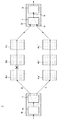
〔第1の実施形態〕次に、本実施形態について図面を参照して詳細に説明する。図1は、本実施形態におけるパス切替制御システム1を示す図である。
[First Embodiment] Next, this embodiment will be described in detail with reference to the drawings. FIG. 1 is a diagram showing a path
〔構成の説明〕図1に示すように、本実施形態におけるパス切替制御システム1は、現用パス2と、予備パス3と、再生中継用光伝送装置4a、4b、4c、4a´、4b´、4c´と、波長送受信端光伝送装置5、5´とを備えている。なお波長送受信端光伝送装置とは、一般的にはライン冗長トランスポンダのことを示し、本実施形態では現用パス2と予備パス3の2つのパスを、1つのライン冗長トランスポンダで運用することができる。
[Description of Configuration] As shown in FIG. 1, the path
パス切替制御システム1において、現用パス2と予備パス3とは冗長パスを構成しており、波長受信端光伝送装置5、5´間で光接続をしている。冗長パスとは、一方のパス(現用パス2)に障害が発生したとき、他方のパス(予備パス3)に切り替え可能な、自動パス切り替え機能を有する構成である。
In the path
再生中継用光伝送装置4は、現用パス2と予備パス3にそれぞれ少なくとも1つ接続して設けられている。なお本実施形態では図1に示すように、上流から下流に向けて現用パス2と予備パス3にそれぞれ3つの再生中継用光伝送装置4a、4b、4c、4a´、4b´、4c´を設けている。
At least one regenerative repeater optical transmission device 4 is connected to each of the working
図1に×で示すように、現用パス2の所定箇所(ここでは4aと4bの間)において障害が発生した場合、障害発生箇所に隣接した下流の再生中継用光伝送装置4bは、光入力信号障害を検出する。ここで、再生中継用光伝送装置4aと4bの間における障害とは、両者をつなぐ光伝送路の抜去等により光を物理的に受信することができなくなる障害だけでなく、再生中継用光伝送装置4aの信号送出機能障害等で伝送される光に含まれる信号フレームに異常がある障害なども含む。
As shown by x in FIG. 1, when a failure occurs in a predetermined location (in this case, between 4a and 4b) of the working
そして再生中継用光伝送装置4bは、光入力信号障害警報を発出し、下流の再生中継用光伝送装置4cへ、伝送障害の警報情報であるAIS信号を送信する。またAIS信号を受信した再生中継用光伝送装置4cは、さらに下流の波長パス送受信端光伝送装置5へAIS信号を転送する。このとき再生中継用光伝送装置4cは、AIS信号に対して処理を行わず、波長パス送受信端光伝送装置5に受信したAIS信号をそのまま転送する。
Then, the regenerative repeater
詳細に説明すると、再生中継用光伝送装置4は、上流側で障害が発生することにより光入力信号障害を検出すると、作成したAIS信号、または受信したAIS信号を下流側に接続している再生中継用光伝送装置4もしくは波長パス送受信端光伝送装置5へ送信する。
More specifically, when the optical transmission device 4 for regenerative repeater detects an optical input signal failure due to the occurrence of a failure on the upstream side, the regeneration that connects the created AIS signal or the received AIS signal to the downstream side. The data is transmitted to the relay optical transmission device 4 or the wavelength path transmission / reception end
波長パス送受信端光伝送装置5は、O/Eコンバータ6と光スイッチ7とを設けている。O/Eコンバータ6は、警報受信モニタ8を有しており、さらに光信号を電気信号に変換する機能を有する。光スイッチ7は、光受信レベルモニタ9、9´を設けており、現用パス2と予備パス3とを切り替える機能を有する。現用パス2と予備パス3は、波長パス送受信端光伝送装置5に接続すると、光スイッチ7の光受信レベルモニタ9、9´を介して、O/Eコンバータ6の警報受信モニタ8と接続している。
The wavelength path transmission / reception end
光受信レベルモニタ9、9´は、現用バス2用と予備パス3用にそれぞれ設けられており、常に両者の光受信レベルをモニタリングしている。一方、警報受信モニタ8は、現用パス2と予備パス3との両方に共通して接続しており、両者から送信されるAIS信号をモニタリングする。つまり警報受信モニタ8は、AIS信号を受信した場合、現用パス2と予備パス3のどちらから送信されたかは判断することができない。
Optical
波長パス送受信端光伝送装置5´は、再生中継用光伝送装置4から転送されたAIS信号をO/Eコンバータ6が有している警報受信モニタ8で受信を行う。
The wavelength path transmission / reception end
O/Eコンバータ6が、警報受信モニタ8においてAIS信号を認識すると、光スイッチ7は現在運用中のパス(現用パス2)から、もう一方のパス(予備パス3)へ切り替えを行う。但し、パスの切り替えを行う際に、光受信レベルモニタ9における切替先のパス(予備パス3)が通常運用時の光入力レベル(通常値)に達していない場合、つまり光レベルが低い場合は切り替えを行わない。
When the O /
詳細に説明すると、波長パス送受信端光伝送装置5´は再生中継用光伝送装置4から転送されAIS信号を警報受信モニタ8で受信すると、光受信レベルモニタ9における予備パス3の光入力レベルの解析を行う。そして光受信レベルモニタ9´が検知した予備パス3の光レベル値が回線運用上問題のない場合、光スイッチ7は現用パス2から予備パス3へ自動的にパス切替を行う。しかし、予備パス3の光入力レベルが通常運用時の光入力レベルに達していない場合は、予備パス3にも障害が発生していると判断して、パスの切替を行わない。
More specifically, when the wavelength path transmission / reception end
なおAIS信号を検出した再生中継用光伝送装置4は、波長パス送受信端光伝送装置5´へAIS信号を一定時間転送する。そして再生中継用光伝送装置4はAIS信号を一定時間転送し続けた後、光出力シャットダウンを実施し、再生中継用光伝送装置4の光信号出力部からの光信号出力を停止する。
The regenerative repeater optical transmission device 4 that has detected the AIS signal transfers the AIS signal to the wavelength path transmission / reception end
なお一定時間とは波長送受信端光伝送装置5´が、現用パス2から予備パス3への切替を完了する時間である。つまりAIS信号を受信した後に、光受信レベルモニタ9が予備パス3の光入力レベルが通常運用時の光レベルであると認識し、光スイッチ7が現用パス2から予備パス3に切替を行うまでの時間である。そのため、例えば波長パス送受信端光伝送装置5´が高性能であり上記のパス切替を瞬時に行うのが可能であれば、AIS信号が送信を行う一定時間を短くすることができる。
The fixed time is a time for the wavelength transmitting / receiving end
上記構成のようにパス切替を行うトリガをAIS信号にすると、パス切替に要する時間は波長送受信端光伝送装置5´の能力に依存して決まる。そのため、再生中継用光伝送装置4bは、VOA(Variable Optical Attenuator)制御等を用いて光出力制御の速度を遅くすることができ、光レベル変動速度を光アンプの出力制御の許容範囲に収めることができる。つまり、再生中継用光伝送装置4bは、光出力をゆっくりシャットダウンしても運用上に問題はない。
When the trigger for performing path switching is an AIS signal as in the above configuration, the time required for path switching is determined depending on the capability of the wavelength transmitting / receiving end
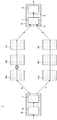
図2に示すように、現用パス2の伝送路障害が復旧した場合、再生中継用光伝送装置4bが光入力信号障害警報の解除を認識し、下流の再生中継用光伝送装置4cへAIS信号の解除情報を転送する。
As shown in FIG. 2, when the transmission path failure of the working
再生中継用光伝送装置4cは、転送されたAIS信号の解除情報を検出すると、波長パス送受信端光伝送装置5へAIS信号の解除情報を転送する。また再生中継用光伝送装置4cはAIS信号の解除情報を受信すると、光出力シャットダウンを解除し通常運用時の光信号出力の再開を行う。
When the regenerative repeater
波長パス送受信端光伝送装置5´は、再生中継用光伝送装置4cからAIS信号の解除情報を受信すると、O/Eコンバータ6が有している警報受信モニタ8で受信を行う。そして波長パス送受信端光伝送装置5´内の光スイッチ7が有する光受信レベルモニタ9は、現用パス2の光受信レベルモニタ値が通常値であることを認識する。
When receiving the AIS signal release information from the regenerative repeater
波長パス送受信端光伝送装置5´は、AIS信号の解除情報と現用パス2の光受信レベルモニタ9の正常が認識すると、障害発生していた伝送路の正常状態復旧を自動的に感知し、予備パス3から現用パス2へ自動的にパス復旧を行い、伝送路障害前の運用状態に戻す。
When the wavelength path transmission / reception end
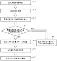
〔動作の説明〕次に図3を用いて、伝送路障害が発生した状態における、現用パス2から予備パス3へ自動パス切替を行う場合の、再生中継用光伝送装置4および波長パス送受信端光伝送装置5の動作について説明する。
[Explanation of Operation] Next, with reference to FIG. 3, the regenerative repeater optical transmission device 4 and the wavelength path transmission / reception terminal when automatic path switching from the working
まずS1において、現用パス2で伝送路障害が発生すると、障害発生箇所に隣接した下流の再生中継用光伝送装置4は、光入力信号障害を検出する。次にS2に処理をすすめる。
First, in S1, when a transmission path failure occurs in the working
次にS2において、再生中継用光伝送装置4は、伝送障害の警報情報であるAIS信号を下流の波長パス送受信端光伝送装置5へ一定時間転送を行う。次にS3に処理を進める。
Next, in S2, the regenerative repeater optical transmission apparatus 4 transfers an AIS signal, which is transmission failure alarm information, to the downstream wavelength path transmission / reception end
次にS3において、波長パス送受信端光伝送装置5は、上流の再生中継用光伝送装置4から転送されたAIS信号を警報受信モニタ8で検出する。次にS4に処理をすすめる。
Next, in
次にS4において、波長パス送受信端光伝送装置5はAIS信号を警報受信モニタ8で検出すると、光受信レベルモニタ9において予備パス3が通常運用時の光入力レベルであるか認識を行う。なお、光受信レベルモニタ9は、常に現用パス2と予備パス3の光受信レベルをモニタリングしている。
Next, in S4, when the wavelength path transmission / reception end
一方、予備パス3が通常運用時の光入力レベルに達していない場合、NOとしてS7に進む。そしてS7では現用パス2から予備パス3への切替は行わない。
On the other hand, if the
S5において、光スイッチ7は、現用パス2から予備パス3へ自動的にパス切替を行う。次に、S6に処理を進める。
In S5, the
次にS6において、再生用中継光伝送装置4は、AIS信号の送信を終了する。次に、S7に処理を進める。 Next, in S6, the reproduction repeater optical transmission apparatus 4 ends the transmission of the AIS signal. Next, the process proceeds to S7.
次にS7において、再生中継用光伝送装置4は光出力シャットダウンを開始する。このとき、現用パス2から予備パス3へのパスの切替は既に完了しているため、光出力シャットダウン速度は再生中継用光伝送装置4に実装されている光アンプのKeepAlive特性に影響がない程度の速度で行うことができる。
In step S7, the regenerative repeater optical transmission device 4 starts optical output shutdown. At this time, since switching of the path from the working
次に図4を用いて、伝送路障害復旧時の状態で、予備パス3から現用パス2へ自動パス復旧を行う場合の、再生中継用光伝送装置4および波長パス送受信端光伝送装置5´の動作について説明する。
Next, referring to FIG. 4, the regenerative repeater optical transmission device 4 and the wavelength path transmission / reception end
まずS11において、現用パス2の伝送路障害が復旧すると、復旧した箇所に隣接した下流の再生中継用光伝送装置4が認識する。次に、S12に処理を進める。
First, in S11, when the transmission path failure of the working
次にS12において、再生中継用光伝送装置4は、AIS解除情報を下流の波長パス送受信端光伝送装置5´へ転送し、光出力シャットダウンの解除を開始して、通常運用時の光出力レベルに戻す。次にS13に処理を進める。
Next, in S12, the regenerative repeater optical transmission device 4 transfers the AIS cancellation information to the downstream wavelength path transmission / reception end
次にS13において、波長パス送受信端光伝送装置5´は上流の再生中継用光伝送装置4から転送されたAIS解除情報を認識する。次にS14に処理を進める。
In step S13, the wavelength path transmission / reception end
次にS14において、波長パス送受信端光伝送装置5´の光受信レベルモニタ9は、再生中継用光伝送装置4bの光出力シャットダウン解除により、現用パス2の光入力レベルが通常運用状態であるか認識する。そして現用パス2の光入力レベルが通常値である場合、YESとしてS15に処理を進める。
Next, in S14, the optical reception level monitor 9 of the wavelength path transmission / reception end optical transmission device 5 'determines whether the optical input level of the working
一方、現用パス2が通常運用時の光入力レベルに達していない場合、NOとしてS16に進む。そしてS16では予備パス3から現用パス2への切替は行わない。
On the other hand, if the working
次にS15において、波長パス送受信端光伝送装置5´は、障害が発生していた現用パス2の障害復旧を認識し、予備パス3から現用パス2への切替であるパス復旧を自動的に実行する。
Next, in S15, the wavelength path transmitting / receiving end
〔効果の説明〕次に本実施形態の効果について説明を行う。 [Explanation of Effects] Next, the effects of this embodiment will be described.
本実施形態におけるパス切替制御システム1は、現用パス2と予備パス3が発生する
障害情報を共通の警報受信モニタ8でモニタリングしている。つまり、現用パス2と予備パス3のそれぞれに、警報受信モニタ8を設けているわけではない。そのため、警報受信モニタ8は、AIS信号を受信した場合、現用パス2と予備パス3のどちらで障害が発生しているか判断することが出来ない。
The path switching
また本実施形態では、現用パス2と予備パス3とにそれぞれ光受信レベルモニタ9、9´を設け、常に光受信レベルが通常値であるかモニタリングしている。そして、一方のパスからAIS信号を受信したときに、光受信レベルが通常値である場合に、パスの切替を行う。つまり、光受信レベルが通常値に近いほうにパスを切り替える。
In the present embodiment, the optical reception level monitors 9 and 9 'are provided for the working
上記構成にすることで、現用パス2と予備パス3の一方で障害が発生しAIS信号を送信した場合に、もし警報受信モニタ8はAIS信号がどちらから送信されたか判断できないとしても、光受信レベルが通常値に近いパスを選択することで、品質を高いパス切替システムを安価に構成することができる。
With the above configuration, when a failure occurs in one of the working
つまり警報受信モニタ8は、現用パス2と予備パス3とにそれぞれ設ける必要がなく、現用パス2と予備パス3に共通して設ければよい。そのため、2つのパスに対して1つの警報受信モニタ8でパス切替制御システム1を構成できるため、さらなるコスト削減や小型化を実現することができる。
That is, it is not necessary to provide the alarm reception monitor 8 for each of the working
なお伝送路障害発生時に、AIS信号のみを認識してパス切り替えを実施すると、次のような課題がある。AISモニタポイントが一つのため、予備パス3の伝送路状態が監視できず、予備パス3の伝送路状態を把握できない。従って、予備パス3にも障害があった場合に、自動パス切替を行っても回線が復旧しないリスクがある。また、予備パス3切替後についても障害が発生した現用パス2の復旧状況が監視できないため、自動復旧できない。
If a path switching is performed by recognizing only the AIS signal when a transmission path failure occurs, there are the following problems. Since there is one AIS monitor point, the transmission path state of the
一方、光受信レベルモニタ9のみを認識してパス切り替えを実施すると、再生中継用光伝送装置4の光出力シャットダウンの速度によって、次のような課題がある。 On the other hand, when only the optical reception level monitor 9 is recognized and path switching is performed, there are the following problems depending on the optical output shutdown speed of the regenerative repeater optical transmission device 4.
光出力シャットダウンが早い場合は、光出力シャットダウンによる光レベル変動が急速のため、再生中継用光伝送装置4に搭載している光アンプのKeep Alive特性を満足することができない。そのため再生中継用光伝送装置4は、障害検出してシャットダウンする波長とともに多重されている他の生き残り波長へのエラーが発生する可能性がある。 When the optical output shutdown is early, the optical level fluctuation due to the optical output shutdown is rapid, so that the keep alive characteristic of the optical amplifier mounted on the optical transmission device 4 for regenerative repeating cannot be satisfied. Therefore, there is a possibility that the regenerative repeater optical transmission device 4 may cause an error to other surviving wavelengths that are multiplexed together with the wavelength that is detected and shut down.
具体例を用いて詳細に説明を行うと、例えば現用パス2が、波長(以下、ch)の異なる光信号を40ch分多重した光信号を伝送していた場合を考える。ここで現用パス2において何かしらの障害が発生し、39ch分の光出力がシャットダウンしてしまった場合、多重光出力レベルは40ch分から1ch分の光レベルに急に変動する。
To explain in detail using a specific example, consider a case where, for example, the working
しかし光出力シャットダウンが早い場合、障害箇所の下流側に設けられた再生中継用光伝送装置4の光アンプはその速さに対応できず、実際1ch分の光レベル信号に対し、40ch分のレベル調整を行ってしまう。その結果、光アンプは過度の光を出力してしまい、障害と関係のない1chの光信号に対しても、エラーが発生してしまう。つまり障害発生した39ch分に光信号を、予備パス3に切り替えることができたとしても、現用パス2に残った正常な1ch分の光信号に対して悪影響を与えてしまう。
However, when the optical output shuts down quickly, the optical amplifier of the regenerative repeater optical transmission device 4 provided downstream of the faulty point cannot cope with the speed, and the actual level of 40 ch is compared to the optical level signal of 1 ch. Make adjustments. As a result, the optical amplifier outputs excessive light, and an error occurs even for a 1ch optical signal not related to a failure. In other words, even if the optical signal can be switched to the
一方、シャットダウン速度が遅い場合には、光レベルの変動にあわせて光アンプのレベル調整を行うことができる。しかし、パス切り替え実施トリガとなる光レベル閾値まで下がる速度が遅いため、パス切り替えが瞬時に実施できず、パス切り替えにおけるネットワークサービスに影響を与えてしまう。 On the other hand, when the shutdown speed is slow, the level of the optical amplifier can be adjusted in accordance with the fluctuation of the light level. However, since the speed of falling to the light level threshold that is a path switching execution trigger is slow, path switching cannot be performed instantaneously, which affects network services in path switching.
そこで本実施形態におけるパス切替システム1は、伝送線路に障害が発生するとAIS信号を送信し、予備パス3の品質監視しながらパスの切替を行う。そのため、現用パス2の光出力ゆっくり落とすことができ、ネットワークにおける信号品質の確保と、自動切り替え及び自動復旧機能を実現することができる。
Therefore, the
上記と同様に具体例を用いて詳細に説明を行う。本実施形態におけるパス切替制御システム1は、波長パス受信端光伝送に光受信レベルモニタ9とAISモニタの両方を具備している。そのため、もし現用バス2において40波多重信号のうち1〜39chに障害が発生したとしても、AIS信号をトリガとして、予備パス3の光入力レベルが問題ない場合は、39ch分の光信号を予備パス3に切り替えを行う。
A detailed description will be given using a specific example as described above. The path switching
ここで現用パス2を伝送する信号は、40chから1chに光レベルに変動するが、1ch分の光信号に対して、再生中継用光伝送装置4の光アンプが適切な光レベル制御できるように、光シャットダウン速度を徐々に遅なるように調整する。
Here, the signal transmitted through the working
つまり本実施形態では、AIS信号による切替で、まずは障害の発生した39ch分の光信号を予備パス3への切替を実施する。予備パス3へ切替られたことで、39ch分に光信号の正常状態を保ちながら、現用パス2の光シャットダウンをゆっくりとすることができる。その結果、光アンプは適切な光レベル制御ができるため、障害が発生しなかった1ch分の光信号は現用パス2のままで正常に動作することができる。
In other words, in the present embodiment, first, switching of the 39 ch optical signals in which a failure has occurred to the
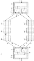
上記の実施形態では、波長パス送受信端光伝送装置5から波長パス送受信端光伝送装置5´に光信号が伝送される場合を記載した。しかし、これに限定されず図5に示すように、双方向の波長パス送受信端光伝送装置5から光信号の伝送を行う場合においても、本実施形態のパス切替制御システム1を適用することができる。
In the above embodiment, the case where an optical signal is transmitted from the wavelength path transmission / reception end
1 パス切替制御システム
2 現用パス
3 予備パス
4a〜4c 再生中継用光伝送装置
4a´〜4c´ 再生中継用光伝送装置
5、5´ 波長パス送受信端光伝送装置
6 O/Eコンバータ
7 光スイッチ
8 警報受信モニタ
9、9´ 光受信レベルモニタ
DESCRIPTION OF
Claims (9)
前記冗長パスに設けられた再生中継用伝送装置と、
前記冗長パスのそれぞれに設けられた光受信レベルモニタと、
前記冗長パスに共通して設けられた警報受信モニタとを備えたことを特徴とするパス切替制御システム。 A redundant path consisting of at least a working path and a backup path;
A regenerative relay transmission device provided in the redundant path;
An optical reception level monitor provided in each of the redundant paths;
A path switching control system comprising: an alarm reception monitor provided in common with the redundant path.
前記光受信レベルモニタの値に基づいて、前記現用パスを切り替える光スイッチを設けていることを特徴とする請求項2に記載のパス切替制御システム。 When the alarm reception monitor receives alarm information,
The path switching control system according to claim 2, further comprising an optical switch that switches the working path based on a value of the optical reception level monitor.
前記警報情報の解除を送信し、再度光信号の出力を開始することを特徴とする請求項2に記載のパス切替制御システム。 When the failure in the working path is recovered, the regenerative relay transmission device
3. The path switching control system according to claim 2, wherein a release of the alarm information is transmitted and output of an optical signal is started again.
前記警報情報を受信すると前記一方のパスと他方のパスにおける光入力レベルを検出し、
前記光入力レベルが所定の通常値に近いパスに切替を行い、
光出力信号の停止を行うことを特徴とするパス切替制御方法。 When a failure occurs on one path, it sends alarm information,
When the alarm information is received, the light input level in the one path and the other path is detected,
The optical input level is switched to a path close to a predetermined normal value,
A path switching control method characterized by stopping an optical output signal.
Priority Applications (1)
| Application Number | Priority Date | Filing Date | Title |
|---|---|---|---|
| JP2011019728A JP2012160938A (en) | 2011-02-01 | 2011-02-01 | Path switching control system and path switching control method |
Applications Claiming Priority (1)
| Application Number | Priority Date | Filing Date | Title |
|---|---|---|---|
| JP2011019728A JP2012160938A (en) | 2011-02-01 | 2011-02-01 | Path switching control system and path switching control method |
Publications (1)
| Publication Number | Publication Date |
|---|---|
| JP2012160938A true JP2012160938A (en) | 2012-08-23 |
Family
ID=46841110
Family Applications (1)
| Application Number | Title | Priority Date | Filing Date |
|---|---|---|---|
| JP2011019728A Pending JP2012160938A (en) | 2011-02-01 | 2011-02-01 | Path switching control system and path switching control method |
Country Status (1)
| Country | Link |
|---|---|
| JP (1) | JP2012160938A (en) |
Citations (7)
| Publication number | Priority date | Publication date | Assignee | Title |
|---|---|---|---|---|
| JPS63221725A (en) * | 1987-03-11 | 1988-09-14 | Nec Corp | Optical transmission system |
| JPH0637783A (en) * | 1992-07-14 | 1994-02-10 | Fujitsu Ltd | Bypass route setting system in atm network |
| JPH10303814A (en) * | 1997-05-02 | 1998-11-13 | Nec Corp | Optical path network and optical path network changeover device |
| JP2000174734A (en) * | 1998-12-08 | 2000-06-23 | Fujitsu Ltd | Transmission path switching system, transmission terminal equipment, repeater, and SDH transmission path switching system |
| JP2000332655A (en) * | 1999-05-20 | 2000-11-30 | Mitsubishi Electric Corp | Optical redundancy switching method for optical wavelength division multiplexing system |
| JP2009212763A (en) * | 2008-03-04 | 2009-09-17 | Nec Corp | Optical transmission system, optical transmitter/receiver and terminal-side receiver used by optical transmission system, and optical transmission method |
| JP2010034877A (en) * | 2008-07-29 | 2010-02-12 | Nippon Telegr & Teleph Corp <Ntt> | Redundant transmission system in point-to-multipoint system |
-
2011
- 2011-02-01 JP JP2011019728A patent/JP2012160938A/en active Pending
Patent Citations (7)
| Publication number | Priority date | Publication date | Assignee | Title |
|---|---|---|---|---|
| JPS63221725A (en) * | 1987-03-11 | 1988-09-14 | Nec Corp | Optical transmission system |
| JPH0637783A (en) * | 1992-07-14 | 1994-02-10 | Fujitsu Ltd | Bypass route setting system in atm network |
| JPH10303814A (en) * | 1997-05-02 | 1998-11-13 | Nec Corp | Optical path network and optical path network changeover device |
| JP2000174734A (en) * | 1998-12-08 | 2000-06-23 | Fujitsu Ltd | Transmission path switching system, transmission terminal equipment, repeater, and SDH transmission path switching system |
| JP2000332655A (en) * | 1999-05-20 | 2000-11-30 | Mitsubishi Electric Corp | Optical redundancy switching method for optical wavelength division multiplexing system |
| JP2009212763A (en) * | 2008-03-04 | 2009-09-17 | Nec Corp | Optical transmission system, optical transmitter/receiver and terminal-side receiver used by optical transmission system, and optical transmission method |
| JP2010034877A (en) * | 2008-07-29 | 2010-02-12 | Nippon Telegr & Teleph Corp <Ntt> | Redundant transmission system in point-to-multipoint system |
Similar Documents
| Publication | Publication Date | Title |
|---|---|---|
| US8396366B2 (en) | Optical safety implementation in protection switching modules | |
| JP6104652B2 (en) | Switching device and transmission system | |
| US7242860B2 (en) | Optical protection switching using 2 by 2 switching functions | |
| KR20090104046A (en) | Network fault detection and protection switching | |
| JP2000174706A (en) | Method and device for automatically controlling output power of optical signal | |
| JP2011019140A (en) | Optical communication apparatus, optical wavelength multiplexing transmission system, optical line failure detecting method, program therefor and program recording medium | |
| US11569907B2 (en) | Per-band fault signaling in a multi-band optical transmission system | |
| JP6024391B2 (en) | Transmission apparatus, transmission system, and fault detection method | |
| JP5849911B2 (en) | Communication system and optical transmission apparatus | |
| JP4422441B2 (en) | Signal switching device | |
| JP5435223B2 (en) | Wavelength division multiplexing transmission apparatus and signal light monitoring method thereof | |
| JP6252476B2 (en) | Multi-failure optical node, optical communication system using the same, and wavelength path switching method | |
| JP4351189B2 (en) | Optical transmission line monitoring method, optical transmission line monitoring program, and optical transmission line monitoring apparatus | |
| JP5863184B2 (en) | Optical transmission system | |
| KR101610808B1 (en) | Dualized optical transceiver for optical communication protection system | |
| JP4755674B2 (en) | Signal switching device and transmission system | |
| JP2012160938A (en) | Path switching control system and path switching control method | |
| JP2005286736A (en) | Wavelength switching control method, variable wavelength transmission apparatus, and variable wavelength transmission system | |
| JP4704261B2 (en) | Optical communication device | |
| JP2010278493A (en) | Optical transmission system | |
| JP2000332695A (en) | Optical amplifier repeater | |
| JP4554238B2 (en) | Optical transceiver | |
| EP1788727A1 (en) | Method to protect human eyes in optical communication system | |
| JP6090876B2 (en) | Transmission apparatus, transmission system, and path switching method | |
| CN1964241A (en) | Optical fiber communication network system and access device and method for node at the above system |
Legal Events
| Date | Code | Title | Description |
|---|---|---|---|
| A621 | Written request for application examination |
Free format text: JAPANESE INTERMEDIATE CODE: A621 Effective date: 20140116 |
|
| A977 | Report on retrieval |
Free format text: JAPANESE INTERMEDIATE CODE: A971007 Effective date: 20140925 |
|
| A131 | Notification of reasons for refusal |
Free format text: JAPANESE INTERMEDIATE CODE: A131 Effective date: 20140930 |
|
| A02 | Decision of refusal |
Free format text: JAPANESE INTERMEDIATE CODE: A02 Effective date: 20150210 |